EP0321607B1 - Supercritical fluids as diluents in liquid spray application of coatings - Google Patents
Supercritical fluids as diluents in liquid spray application of coatings Download PDFInfo
- Publication number
- EP0321607B1 EP0321607B1 EP87119281A EP87119281A EP0321607B1 EP 0321607 B1 EP0321607 B1 EP 0321607B1 EP 87119281 A EP87119281 A EP 87119281A EP 87119281 A EP87119281 A EP 87119281A EP 0321607 B1 EP0321607 B1 EP 0321607B1
- Authority
- EP
- European Patent Office
- Prior art keywords
- mixture
- liquid
- viscosity
- carbon dioxide
- coating
- Prior art date
- Legal status (The legal status is an assumption and is not a legal conclusion. Google has not performed a legal analysis and makes no representation as to the accuracy of the status listed.)
- Expired - Lifetime
Links
Images


Classifications
-
- B—PERFORMING OPERATIONS; TRANSPORTING
- B05—SPRAYING OR ATOMISING IN GENERAL; APPLYING FLUENT MATERIALS TO SURFACES, IN GENERAL
- B05C—APPARATUS FOR APPLYING FLUENT MATERIALS TO SURFACES, IN GENERAL
- B05C1/00—Apparatus in which liquid or other fluent material is applied to the surface of the work by contact with a member carrying the liquid or other fluent material, e.g. a porous member loaded with a liquid to be applied as a coating
-
- B—PERFORMING OPERATIONS; TRANSPORTING
- B05—SPRAYING OR ATOMISING IN GENERAL; APPLYING FLUENT MATERIALS TO SURFACES, IN GENERAL
- B05D—PROCESSES FOR APPLYING FLUENT MATERIALS TO SURFACES, IN GENERAL
- B05D1/00—Processes for applying liquids or other fluent materials
- B05D1/02—Processes for applying liquids or other fluent materials performed by spraying
- B05D1/025—Processes for applying liquids or other fluent materials performed by spraying using gas close to its critical state
-
- B—PERFORMING OPERATIONS; TRANSPORTING
- B05—SPRAYING OR ATOMISING IN GENERAL; APPLYING FLUENT MATERIALS TO SURFACES, IN GENERAL
- B05B—SPRAYING APPARATUS; ATOMISING APPARATUS; NOZZLES
- B05B12/00—Arrangements for controlling delivery; Arrangements for controlling the spray area
- B05B12/14—Arrangements for controlling delivery; Arrangements for controlling the spray area for supplying a selected one of a plurality of liquids or other fluent materials or several in selected proportions to a spray apparatus, e.g. to a single spray outlet
- B05B12/1418—Arrangements for controlling delivery; Arrangements for controlling the spray area for supplying a selected one of a plurality of liquids or other fluent materials or several in selected proportions to a spray apparatus, e.g. to a single spray outlet for supplying several liquids or other fluent materials in selected proportions to a single spray outlet
-
- B—PERFORMING OPERATIONS; TRANSPORTING
- B05—SPRAYING OR ATOMISING IN GENERAL; APPLYING FLUENT MATERIALS TO SURFACES, IN GENERAL
- B05B—SPRAYING APPARATUS; ATOMISING APPARATUS; NOZZLES
- B05B7/00—Spraying apparatus for discharge of liquids or other fluent materials from two or more sources, e.g. of liquid and air, of powder and gas
- B05B7/24—Spraying apparatus for discharge of liquids or other fluent materials from two or more sources, e.g. of liquid and air, of powder and gas with means, e.g. a container, for supplying liquid or other fluent material to a discharge device
- B05B7/26—Apparatus in which liquids or other fluent materials from different sources are brought together before entering the discharge device
- B05B7/28—Apparatus in which liquids or other fluent materials from different sources are brought together before entering the discharge device in which one liquid or other fluent material is fed or drawn through an orifice into a stream of a carrying fluid
- B05B7/32—Apparatus in which liquids or other fluent materials from different sources are brought together before entering the discharge device in which one liquid or other fluent material is fed or drawn through an orifice into a stream of a carrying fluid the fed liquid or other fluent material being under pressure
-
- B—PERFORMING OPERATIONS; TRANSPORTING
- B05—SPRAYING OR ATOMISING IN GENERAL; APPLYING FLUENT MATERIALS TO SURFACES, IN GENERAL
- B05D—PROCESSES FOR APPLYING FLUENT MATERIALS TO SURFACES, IN GENERAL
- B05D2401/00—Form of the coating product, e.g. solution, water dispersion, powders or the like
- B05D2401/90—Form of the coating product, e.g. solution, water dispersion, powders or the like at least one component of the composition being in supercritical state or close to supercritical state
-
- Y—GENERAL TAGGING OF NEW TECHNOLOGICAL DEVELOPMENTS; GENERAL TAGGING OF CROSS-SECTIONAL TECHNOLOGIES SPANNING OVER SEVERAL SECTIONS OF THE IPC; TECHNICAL SUBJECTS COVERED BY FORMER USPC CROSS-REFERENCE ART COLLECTIONS [XRACs] AND DIGESTS
- Y10—TECHNICAL SUBJECTS COVERED BY FORMER USPC
- Y10S—TECHNICAL SUBJECTS COVERED BY FORMER USPC CROSS-REFERENCE ART COLLECTIONS [XRACs] AND DIGESTS
- Y10S239/00—Fluid sprinkling, spraying, and diffusing
- Y10S239/01—Pattern sprinkler
Definitions
- This invention relates in general to a process and apparatus for coating substrates.
- this invention is directed to a process and apparatus for coating substrates in which a supercritical fluid, such as supercritical carbon dioxide fluid, is used as a viscosity reduction diluent for coating formulations.
- a supercritical fluid such as supercritical carbon dioxide fluid
- Coatings applied with organic solvents at high solids levels avoid many of the pitfalls of powder and waterborne coatings.
- the molecular weight of the polymer has been decreased and reactive functionality has been incorporated therein so that further polymerization and crosslinking can take place after the coating has been applied. It has been hoped that this type of coating will meet the ever-increasing regulatory requirements and yet meet the most exacting coatings performance demands.
- Present high solids systems have difficulty in application to vertical surfaces without running and sagging of the coating. Often they are also prone to cratering and pin holing of the coating. If they possess good reactivity, they often have poor shelf and pot life. However, if they have adequate shelf stability, they cure and/or crosslink slowly or require high temperature to effect an adequate coating of the substrate.
- U. S. Patent 4,582,731 discloses a method and apparatus for the deposition of thin films and the formation of powder coatings through the molecular spray of solutes dissolved in organic and supercritical fluid solvents.
- the molecular sprays disclosed in the Smith patent are composed of droplets having diameters of about 30 Anstroms. These droplets are more than 106 to 109 less massive than the droplets formed in conventional application methods which Smith refers to as "liquid spray" applications.
- the disclosed method of depositing thin films also seeks to minimize, and preferably eliminate, the presence of solvent within the film deposited upon a substrate. This result is preferably accomplished through the maintenance of reduced pressure in the spray environment.
- low solvent concentration within the deposited film leads to the same problems encountered through the use of high solids coatings.
- DE-A-28 53 066 discloses a method of coating the surface of porous powders or porous bodies and textiles with protecting or decorative layers, in which method the material to be protected is contacted with a gas as a fluid in the supercritical condition. Said gas contains the solid or liquid coating substance. It is mainly concerned with a method of preparing active catalysts.
- the problem to be solved by the present invention was to provide a process and apparatus for the liquid spray application of coatings to a substrate wherein the use of environmentally undesirable organic diluents is minimized and wherein an environmentally safe, non-polluting diluent is used to thin very highly viscous polymer and coatings compositions to liquid spray application consistency.
- a diluent would allow utilization of the best aspects of organic solvent borne coatings applications and performance while reducing the environmental concerns to an acceptable level.
- Such a coating system could meet the requirements of shop- and field-applied liquid spray coatings as well as factory-applied finishes and still be in compliance with environmental regulations.
- the compressibility of supercritical fluids is great just above the critical temperature where small changes in pressure result in large changes in the density of the supercritical fluid.
- the "liquid-like" behavior of a supercritical fluid at higher pressures results in greatly enhanced solubilizing capabilities compared to those of the "subcritical" component, with higher diffusion coefficients and an extended useful temperature range compared to liquids. Components of high molecular weight can often be dissolved in the supercritical fluid at relatively low temperatures.
- Near supercritical liquids also demonstrate solubility characteristics and other pertinent properties similar to those of supercritical fluids.
- the solute may be a liquid at the supercritical temperatures, even though it is a solid at lower temperatures.
- fluid "modifiers” can often alter supercritical fluid properties significantly, even in relatively low concentrations, greatly increasing solubility for some solutes. These variations are considered to be within the concept of a supercritical fluid as used in the context of this invention. Therefore, as used herein, the phrase "supercritical fluid” denotes a component above, at or slightly below the critical temperature and pressure of that component.
- supercritical carbon dioxide fluid Due to the low cost, low toxicity and low critical temperature of carbon dioxide, supercritical carbon dioxide fluid is preferably used in the practice of the present invention. However, use of any of the aforementioned supercritical fluids and mixtures thereof are to be considered within the scope of the present invention.
- the polymeric components suitable for use in this invention as coating materials are any of the polymers known to those skilled in the coatings art. Again, the only limitation to their use in the present invention is their degradation at the temperatures or pressures involved with their admixture with the supercritical fluid. These include vinyl, acrylic, styrenic and interpolymers of the base vinyl, acrylic and styrenic monomers; polyesters, oilless alkyds, alkyds and the like; polyurethanes, two package polyurethane, oil-modified polyurethanes, moisture-curing polyurethanes and thermoplastic urethanes systems; cellulosic esters such is acetate butyrate and nitrocellulose; amino-resins such as urea formaldehyde, malamine formaldehyde and other aminoplast polymers and resins materials; natural gums and resins. Also included are crosslinkable film forming systems.
- the polymer component of the coating composition is generally present in amounts ranging from 5 to 65 wt.%, based upon the total weight of the polymer(s), solvent(s) and supercritical fluid diluent.
- the polymer component should be present in amounts ranging from about 15 to about 55 wt.% on the same basis.
- the supercritical fluid should be present in quantities such that a liquid mixture is formed which possesses a viscosity such that it may be applied as a liquid spray. Generally, this requires the mixture to have a viscosity of less than about 150 cps. Examples of known supercritical fluids have been set forth priviously herein.
- the viscosity of the mixture of components must be less than that which effectively prohibits the liquid spray application of the mixture. Generally, this requires that the mixture possess a viscosity of less than about 150 mPa ⁇ s.
- the viscosity of the mixture of components ranges from about 10 mPa ⁇ s to about 100 mPa ⁇ s. Most preferably, the viscosity of the mixture of components ranges from about 20 mPa ⁇ s to about 50 mPa ⁇ s.
- supercritical carbon dioxide fluid is employed as the supercritical fluid diluent, it preferably should be present in amounts ranging from 10 to about 60 wt.% based upon the total weight of components (a), (b) and (c). Most preferably, it is present in amounts ranging from 20-60 wt.% on the same basis, thereby producing a mixture of components (a), (b) and (c) having viscosities from about 20 mPa ⁇ s to about 50 mPa ⁇ s.
- the composition may at some point separate into two distinct phases. This perhaps is best illustrated by the phase diagram in Figure 1 wherein the supercritical fluid is supercritical carbon dioxide fluid.
- the vertices of the triangular diagram represent the pure components of the coating formulation. Vertex A is the active solvent, vertex B carbon dioxide, vertex C the polymeric material.
- the curved line BFC represents the phase boundary between one phase and two phases.
- the point D represents a possible composition of the coating composition before the addition of supercritical carbon dioxide.
- the point E represents a possible composition of the coating formulation.
- the addition of supercritical carbon dioxide has reduced the viscosity of the viscous coatings composition to a range where it can be readily atomized through a properly designed liquid spray apparatus. After atomization, a majority of the carbon dioxide vaporizes, leaving substantially the composition of the original viscous coatings formulation. Upon contacting the substrate, the remaining liquid mixture of the polymer and solvent(s) component(s) will flow to produce a uniform, smooth film on the substrate.
- the film forming pathway is illustrated in Figure 1 by the line segments EE'D (atomization and decompression) and DC (coalescense and film formation).
- the active solvent(s) suitable for the practice of this invention generally include any solvent or mixtures of solvents which is miscible with the supercritical fluid and is a good solvent for the polymer system. It is recognized that some organic solvents, such as cyclohexanol, have utility as both conventional solvents and as supercritical fluid diluents. As used herein, the term "active solvent” does not include solvents in the supercritical state.
- ketones such as acetone, methyl ethyl ketone, methyl isobutyl ketone, miestyl oxide, methyl amyl ketone, cyclohexanone and other aliphatic ketones
- esters such as methyl acetate, ethyl acetate, alkyl carboxylic esters, methyl t-butyl ethers, dibutyl ether, methyl phenyl ether and other aliphatic or alkyl aromatic ethers
- glycol ethers such ethoxyethanol, butoxyethanol, ethoxypropanol, propoxyethanol, butoxpropanol and other glycol ethers
- glycol ether ester such as butoxyethoxy acetate, ethyl ethoxy proprionate and other glycol ether esters
- alcohols such methanol, ethanol, propanol, 2-propanol, butanol, amyl alcohol and other aliphatic keto
- the solvent(s) should be present in amounts ranging from 0 to about 70 wt.% based upon the total weight of the polymer(s), solvent(s) and supercritical fluid diluent. Most preferably, the solvent(s) are present in amounts ranging from about 5 to 50 wt.% on the same basis.
- the coating formulation employed in the process of the present invention include a polymeric compound(s), a supercritical fluid diluent(s), and optionally, an active solvent(s). Pigments, drying agents, anti-skinning agents and other additives well known in the art may also be included on the compositions applied by the claimed process.
- Solvents other than the active solvents may also be used in the practice of the present invention. These solvents are typically those in which the polymeric compound(s) have only limited solubility. However, these solvents are soluble in the active solvent and therefore constitute an economically attractive route to viscosity reduction of the spray mixture. Examples of these solvents include lower hydrocarbon compounds.
- the present process may be used to apply coatings by the application of liquid spray techniques to a variety of substrates.
- substrates in therefore not critical in the practice of the present invention.
- suitable substrates include wood, glass, ceramic, metal and plastics.
- the environment in which the liquid spray of the present invention is conducted is not narrowly critical.
- the pressure therein must be less than that required to maintain the supercritical fluid component of the liquid spray mixture in the supercritical state.
- the present invention is conducted under conditions at or near atmospheric pressure.
- curing of the coating composition present upon the coated substrate may be performed at this point by conventional means, such as allowing for evaporation of the active solvent, application of heat or ultraviolet light, etc.
- the spray composition is preferably heated prior to atomization.
- liquid spray mixture (a), (b) and optionally (c) is not necessary in the practice of the present invention. However, it is often preferred to initially mix the polymer(s) (a) and any active solvent(s) (c) used due to the relatively high viscosities normally exhibited by many polymer components.
- the invention is directed to an apparatus useful for blending and dispensing of the liquid spray coating formulations.
- the apparatus in which the process of this invention is conducted is illustrated in Figure 2.
- the viscous coatings composition is fed from reservoir A to the suction side of metering gear pump B.
- Carbon dioxide used as the supercritical fluid for the purposes of this Figure, is fed to the system from the tank C which is provided with a pressure controller and heating coil to adjust the pressure to the desired level.
- the carbon dioxide is fed into the system through a pressure controller to the input side of the metering pump B but downstream from the circulation loop E. Sufficient carbon dioxide is admitted to the stream so as to bring the composition into the critical composition range (EE′) as previously noted above with respect to Figure 1.
- the mixture is then fed through a mixing device F, where it is mixed until the composition has a uniformly low viscosity. Thereafter, the mixture is heated through heat exchanger G to avoid condensation of carbon dioxide and ambient water vapor. The mixture is then forced out spray nozzle J where atomization takes place. The atomized coating composition solution may then be directed into a fan produced with make up gaseous carbon dioxide through the angled orifices of the spray nozzle. The make up gas is heated through heat exchanger K.
- FIG. 4 is a section of the phase diagram showing the composition for which the viscosity has been determined.
- the phase boundary is illustrated by the line segment AB; the points 1-11 represents the compositions of the mixtures for which the viscosities were measured.
- the phase boundary is illustrated by the shaded line AB.
- Figure 5 illustrates the viscosity versus composition relationship for a 65% viscous polymer solution in methyl amyl ketone (MAK).
- MAK methyl amyl ketone
- the pressure was 8 720 kPa (1250 psig) and the temperature 50°C.
- the polymer employed was AcryloidTM AT-400, a product of Rohm and Haas Company which contains 75% nonvolatile acrylic polymer dissolved in 25% MAK.
- Example illustrates the practice of the present process in a continuous mode.
- Table 2 contains a listing of the equipment used in conducting the procedure described in the Example.
- the coating solution was supplied to the primary pump (8) from 7.57 l (two-gallon) pressure tank (17). After being pressurized in the pump to spray pressure, the solution was then heated in an electric heater (20) to reduce its viscosity (to aid mixing with carbon dioxide), filtered in a fluid filter (21) to remove particulates, and fed through a check valve (22) into the mix point with carbon dioxide.
- the secondary pump (7) on the proportioning Pump unit (9) was used to pump the liquid carbon dioxide.
- a double-acting piston pump (7) with a four-check-valve design was used because of the high vapor pressure of carbon dioxide.
- the pump has an inlet and an outlet on each side of the piston, and no flow occurs through the piston.
- the proportion of carbon dioxide pumped into the spray solution is varied by moving the pump along the moving shaft. Bone-dry-grade liquid carbon dioxide was supplied from cylinder (3) to the secondary pump. Air or gaseous carbon dioxide in the Hoke cylinder (3) was vented through valve (5) as the cylinder was filled.
- the Hoke cylinder (3) was mounted on a scale so that the amount of carbon dioxide in it could be weighed. After the Hoke cylinder (3) was filled with liquid carbon dioxide, it was pressurized with nitrogen from supply (6) to increase the pressure in the cyclinder (3) to above the vapor pressure of the carbon dioxide, in order to prevent cavitation in pump (7) caused by pressure drop across the inlet check valve during the suction stroke. After being pressurized to spray pressure in pump (7), the liquid carbon dioxide was fed unheated through a check valve (23) to the mix point with the coating solution.
- the spray pressure was adjusted to 12167 kPa (1750 psig)and the spray temperature to 60 C.
- a clear one-phase solution was seen in the Jerguson site glass (29).
- the liquid spray mixture contained 46% nonvolatile polymer solids, 24% volatile organic solvents, and 30% carbon dioxide.
- a liquid spray coating was applied to the Test panel (31).
- the test panel (31) was then baked in a convection oven for twenty minutes at a temperature of 120°C.
- the clear coating that was produced had an average thickness of 30.48 ⁇ m (1.2 mils), a distinctness of image of 80%, and a gloss of 90% (measured at an angle of 20 degrees from perpendicular).
Abstract
Description
- This invention relates in general to a process and apparatus for coating substrates. In one aspect, this invention is directed to a process and apparatus for coating substrates in which a supercritical fluid, such as supercritical carbon dioxide fluid, is used as a viscosity reduction diluent for coating formulations.
- Prior to the present invention, the liquid spray application of coatings, such as lacquers, enamels and varnishes, was effected solely through the use of organic solvents as viscosity reduction diluents. However, because of increased environmental concern, efforts have been directed to reducing the pollution resulting from painting and finishing operations. For this reason there has been a great deal of emphasis placed on the development of new coatings technologies which diminish the emission of organic solvent vapors. A number of technologies have emerged as having met most but not all of the performance and application requirements, and at the same time meeting emission requirements and regulations. They are: (a) powder coatings, (b) water-borne dispersions, (c) water-borne solutions, (d) non-aqueous dispersions, and (e) high solids coatings. Each of these technologies has been employed in certain applications and each has found a niche in a particular industry. However, at the present time, none has provided the performance and application properties that were initially expected.
- Powder coatings, for example, while providing ultra low emission of organic vapors, are characterized by poor gloss or good gloss with heavy orange peel, poor definition of image gloss (DOI), and poor film uniformity. Pigmentation of powder coatings is often difficult, requiring at times milling and extrusion of the polymer-pigment composite mixture followed by cryogenic grinding. In addition, changing colors of the coating often requires its complete cleaning, because of dust contamination of the application equipment and finishing area.
- Water borne coatings cannot be applied under conditions of high relative humidity without serious coating defects. These defects result from the fact that under conditions of high humidity, water evaporates more slowly than the organic cosolvents of the coalescing aid, and as might be expected in the case of aqueous dispersions, the loss of the organic cosolvent/coalescing aid interferes with film formation. Poor gloss, poor uniformity, and pin holes unfortunately often result. Additionally, water borne coatings are not as resistant to corrosive environments as are the more conventional solvent borne coatings.
- Coatings applied with organic solvents at high solids levels avoid many of the pitfalls of powder and waterborne coatings. However, in these systems the molecular weight of the polymer has been decreased and reactive functionality has been incorporated therein so that further polymerization and crosslinking can take place after the coating has been applied. It has been hoped that this type of coating will meet the ever-increasing regulatory requirements and yet meet the most exacting coatings performance demands. However, there is a limit as to the ability of this technology to meet the performance requirement of a commercial coating operation. Present high solids systems have difficulty in application to vertical surfaces without running and sagging of the coating. Often they are also prone to cratering and pin holing of the coating. If they possess good reactivity, they often have poor shelf and pot life. However, if they have adequate shelf stability, they cure and/or crosslink slowly or require high temperature to effect an adequate coating of the substrate.
- U. S. Patent 4,582,731 (Smith) discloses a method and apparatus for the deposition of thin films and the formation of powder coatings through the molecular spray of solutes dissolved in organic and supercritical fluid solvents. The molecular sprays disclosed in the Smith patent are composed of droplets having diameters of about 30 Anstroms. These droplets are more than 10⁶ to 10⁹ less massive than the droplets formed in conventional application methods which Smith refers to as "liquid spray" applications. The disclosed method of depositing thin films also seeks to minimize, and preferably eliminate, the presence of solvent within the film deposited upon a substrate. This result is preferably accomplished through the maintenance of reduced pressure in the spray environment. However, low solvent concentration within the deposited film leads to the same problems encountered through the use of high solids coatings. The maintenance of reduced pressures is also not feasible for most commercial coating applications. Furthermore, the spray method disclosed by Smith utilizes very high solvent to solute ratios, thereby requiring undesirably high solvent usage and requiring prohibitively long application times in order to achieve coatings having sufficient thicknesses to impart the desired durability to the coating.
- DE-A-28 53 066 discloses a method of coating the surface of porous powders or porous bodies and textiles with protecting or decorative layers, in which method the material to be protected is contacted with a gas as a fluid in the supercritical condition.
Said gas contains the solid or liquid coating substance. It is mainly concerned with a method of preparing active catalysts. - Clearly, the problem to be solved by the present invention was to provide a process and apparatus for the liquid spray application of coatings to a substrate wherein the use of environmentally undesirable organic diluents is minimized and wherein an environmentally safe, non-polluting diluent is used to thin very highly viscous polymer and coatings compositions to liquid spray application consistency. Such a diluent would allow utilization of the best aspects of organic solvent borne coatings applications and performance while reducing the environmental concerns to an acceptable level. Such a coating system could meet the requirements of shop- and field-applied liquid spray coatings as well as factory-applied finishes and still be in compliance with environmental regulations.
- In its broad aspect, this invention is directed to a process for the liquid spray application of coatings to a substrate wherein in a closed system a liquid mixture is formed containing at least one polymeric component (a) capable of forming a coating on a substrate and a component (b), and then spraying said liquid mixture onto a substrate to form a liquid coating thereon.
- Further the invention is directed to an apparatus for the accomplishment of the process comprising
- (1) means for supplying at least one polymeric component (a) capable of forming a continuous, adherent coating;
- (2) means for optionally supplying at least one active organic solvent (c) and
- (3) means for supplying supercritical carbon dioxide fluid.
Said process is characterized in that said component (b) comprises at least one supercritical fluid in at least an amount which when added to (a) is sufficient to render the viscosity of said mixture of (a) and (b) to a point suitable for spray application and optionally at least one active solvent (c) in which said at least one polymeric component (a) is soluble and which is at least partially miscible with the supercritical fluid, said solvent (c) being present in an amount such that the viscosity of the mixture of (a) and (c) is greater than that desirable for liquid spray application, and spraying said liquid mixture, forming droplets having an average diameter of 1 micron or greater, onto the substrate to form a liquid coating thereon.
Said apparatus is characterized by - (4) means for forming a liquid mixture of components supplied from (1)-(3) and
- (5) means for spraying said liquid mixture forming droplets having an average diameter of 1 micron or greater onto a substrate to form a liquid coating thereon.
- A more detailed understanding of the invention will be had by reference to the drawings wherein:
- Figure 1 is a phase diagram of supercritical carbon dioxide spray coating.
- Figure 2 is a schematic diagram of the liquid spray apparatus employed in the process of the invention.
- Figure 3 is a schematic diagram of the apparatus which can be used to determine the phase relationship of supercritical carbon dioxide in solvent borne coating compositions.
- Figure 4 is a section of a phase diagram showing a composition for which the viscosity has been determined.
- Figure 5 is a graph illustrating the viscosity versus composition relationship for a 65 percent viscous polymer solution in methyl amyl ketone (MAK).
- Figure 6 is a graph showing viscosity when pressure is applied to a viscous polymeric solution.
- Figure 7 is a schematic diagram of a spray apparatus that can be used in the practice of the present invention.
- It has been found that by using the process and apparatus of the present invention, coatings can be applied to a wide variety of substrates in a manner which poses a reduced environmental hazard. Consequently, the use of organic diluents as vehicles for coating formulations can be greatly reduced by utilizing supercritical fluids, such as supercritical carbon dioxide, therewith.
- Because of its importance to the claimed process, a brief discussion of relevant supercritical fluid phenomena is warranted.
- At high pressures above the critical point, the resulting supercritical fluid, or "dense gas", will attain densities approaching those of a liquid and will assume some of the properties of a liquid. These properties are dependent upon the fluid composition, temperature, and pressure.
- The compressibility of supercritical fluids is great just above the critical temperature where small changes in pressure result in large changes in the density of the supercritical fluid. The "liquid-like" behavior of a supercritical fluid at higher pressures results in greatly enhanced solubilizing capabilities compared to those of the "subcritical" component, with higher diffusion coefficients and an extended useful temperature range compared to liquids. Components of high molecular weight can often be dissolved in the supercritical fluid at relatively low temperatures.
- An interesting phenomenon associated with supercritical fluids is the occurrence of a "threshold pressure" for solubility of a high molecular weight solute. As the pressure is increased, the solubility of the solute will often increase by many orders of magnitude with only a small pressure increase.
- Near supercritical liquids also demonstrate solubility characteristics and other pertinent properties similar to those of supercritical fluids. The solute may be a liquid at the supercritical temperatures, even though it is a solid at lower temperatures. In addition, it has been demonstrated that fluid "modifiers" can often alter supercritical fluid properties significantly, even in relatively low concentrations, greatly increasing solubility for some solutes. These variations are considered to be within the concept of a supercritical fluid as used in the context of this invention. Therefore, as used herein, the phrase "supercritical fluid" denotes a component above, at or slightly below the critical temperature and pressure of that component.
- Examples of components which are known to have utility as supercritical fluids are given in Table 1.
TABLE 1 EXAMPLES OF SUPERCRITICAL SOLVENTS Compound Boiling Point °C Critical Temperature °C Critical Pressure kPa (atm) Critical Density g/cm³ CO₂ - 78.5 31.3 7 386 (72.9) 0.448 NH₃ - 33.35 132.4 11 398 (112.5) 0.235 H₂O 100.00 374.15 22 118 (218.3) 0.315 N₂O -88.56 36.5 7 265 (71.7) 0.45 Methane -164.00 -82.1 4 640 (45.8) 0.2 Ethane -88.63 32.28 4 873 (48.1) 0.203 Ethylene -103.7 9.21 5 036 (49.7) 0.218 Propane -42.1 96.67 4 245 (41.9) 0.217 Pentane 36.1 196.6 3 374 (33.3) 0.232 Methanol 64.7 240.5 7 994 (78.9) 0.272 Ethanol 78.5 243.0 6 383 (63.0) 0.276 Isopropanol 82.5 235.3 4 762 (47.0) 0.273 Isobutanol 108.0 275.0 4 296 (42.4) 0.272 Chlorotrifluoromethane 31.2 28.0 3 921 (38.7) 0.579 Monofluoromethane 78.4 44.6 5 877 (58.0) 0.3 Cyclohexanol 155.65 356.0 3 850 (38.0) 0.273 - The utility of any of the above-mentioned compounds as supercritical fluids in the practice of the present invention will depend upon the polymeric compound(s) and active solvent(s) used because the spray temperature cannot exceed the temperature at which thermal degradation of any component of the liquid spray mixture occurs.
- Due to the low cost, low toxicity and low critical temperature of carbon dioxide, supercritical carbon dioxide fluid is preferably used in the practice of the present invention. However, use of any of the aforementioned supercritical fluids and mixtures thereof are to be considered within the scope of the present invention.
- The solvency of supercritical carbon dioxide is like that of a lower aliphatic hydrocarbon (e.g., butane, pentane or hexane) and, as a result, one can consider supercritical carbon dioxide fluid as a replacement for the hydrocarbon diluent portion of a conventional solvent borne coating formulations. Moreover, while lower aliphatic hydrocarbons are much too volatile for use in conventional coatings formulation because of the inherent explosive and fire hazard they present, carbon dioxide is non-flammable, non-toxic and environmentally acceptable. Safety benefits therefore also result in its use in the claimed process.
- The polymeric components suitable for use in this invention as coating materials are any of the polymers known to those skilled in the coatings art. Again, the only limitation to their use in the present invention is their degradation at the temperatures or pressures involved with their admixture with the supercritical fluid. These include vinyl, acrylic, styrenic and interpolymers of the base vinyl, acrylic and styrenic monomers; polyesters, oilless alkyds, alkyds and the like; polyurethanes, two package polyurethane, oil-modified polyurethanes, moisture-curing polyurethanes and thermoplastic urethanes systems; cellulosic esters such is acetate butyrate and nitrocellulose; amino-resins such as urea formaldehyde, malamine formaldehyde and other aminoplast polymers and resins materials; natural gums and resins. Also included are crosslinkable film forming systems.
- The polymer component of the coating composition is generally present in amounts ranging from 5 to 65 wt.%, based upon the total weight of the polymer(s), solvent(s) and supercritical fluid diluent. Preferably, the polymer component should be present in amounts ranging from about 15 to about 55 wt.% on the same basis.
- The supercritical fluid should be present in quantities such that a liquid mixture is formed which possesses a viscosity such that it may be applied as a liquid spray. Generally, this requires the mixture to have a viscosity of less than about 150 cps. Examples of known supercritical fluids have been set forth priviously herein. The viscosity of the mixture of components must be less than that which effectively prohibits the liquid spray application of the mixture. Generally, this requires that the mixture possess a viscosity of less than about 150 mPa·s. Preferably, the viscosity of the mixture of components ranges from about 10 mPa·s to about 100 mPa·s. Most preferably, the viscosity of the mixture of components ranges from about 20 mPa·s to about 50 mPa·s.
- If supercritical carbon dioxide fluid is employed as the supercritical fluid diluent, it preferably should be present in amounts ranging from 10 to about 60 wt.% based upon the total weight of components (a), (b) and (c). Most preferably, it is present in amounts ranging from 20-60 wt.% on the same basis, thereby producing a mixture of components (a), (b) and (c) having viscosities from about 20 mPa·s to about 50 mPa·s.
- If a polymeric component is mixed with increasing amounts of supercritical fluid in the absence of hydrocarbon solvent, the composition may at some point separate into two distinct phases. This perhaps is best illustrated by the phase diagram in Figure 1 wherein the supercritical fluid is supercritical carbon dioxide fluid. In Figure 1 the vertices of the triangular diagram represent the pure components of the coating formulation. Vertex A is the active solvent, vertex B carbon dioxide, vertex C the polymeric material. The curved line BFC represents the phase boundary between one phase and two phases. The point D represents a possible composition of the coating composition before the addition of supercritical carbon dioxide. The point E represents a possible composition of the coating formulation. The addition of supercritical carbon dioxide has reduced the viscosity of the viscous coatings composition to a range where it can be readily atomized through a properly designed liquid spray apparatus. After atomization, a majority of the carbon dioxide vaporizes, leaving substantially the composition of the original viscous coatings formulation. Upon contacting the substrate, the remaining liquid mixture of the polymer and solvent(s) component(s) will flow to produce a uniform, smooth film on the substrate. The film forming pathway is illustrated in Figure 1 by the line segments EE'D (atomization and decompression) and DC (coalescense and film formation).
- The active solvent(s) suitable for the practice of this invention generally include any solvent or mixtures of solvents which is miscible with the supercritical fluid and is a good solvent for the polymer system. It is recognized that some organic solvents, such as cyclohexanol, have utility as both conventional solvents and as supercritical fluid diluents. As used herein, the term "active solvent" does not include solvents in the supercritical state.
- Among suitable active solvents are: ketones such as acetone, methyl ethyl ketone, methyl isobutyl ketone, miestyl oxide, methyl amyl ketone, cyclohexanone and other aliphatic ketones; esters such as methyl acetate, ethyl acetate, alkyl carboxylic esters, methyl t-butyl ethers, dibutyl ether, methyl phenyl ether and other aliphatic or alkyl aromatic ethers; glycol ethers such ethoxyethanol, butoxyethanol, ethoxypropanol, propoxyethanol, butoxpropanol and other glycol ethers; glycol ether ester such as butoxyethoxy acetate, ethyl ethoxy proprionate and other glycol ether esters; alcohols such methanol, ethanol, propanol, 2-propanol, butanol, amyl alcohol and other aliphatic alcohols; aromatic hydrocarbons such as toluene, xylene, and other aromatics or mixtures of aromatic solvents; nitro alkanes such as 2-nitropropane. Generally, solvents suitable for this invention must have the desired solvency characteristics as aforementioned and also the proper balance of evaporation rates so as to insure good coating formation. A review of the structural relationships important to the choice of solvent or solvent blend is given by Dileep et al., Ind. Eng. Che. (Product Research and Development) 24, 162, 1985 and Francis, A. W., J. Phys. Chem. 58, 1099, 1954.
- In order to minimize the unnecessary release of any active solvent present in the liquid spray mixture, the amount of active solvent used should be less than that required to produce a mixture of polymeric compounds and active solvent having a viscosity which will permit its application by liquid spray techniques. In other words, the inclusion of active solvent(s) should be minimized such that the diluent effect due to the presence of the supercritical fluid diluent is fully utilized. Generally, this requires that the mixture of polymeric compounds and active solvent have a viscosity of not less than about 150 mPa·s.
- Preferably, the solvent(s) should be present in amounts ranging from 0 to about 70 wt.% based upon the total weight of the polymer(s), solvent(s) and supercritical fluid diluent. Most preferably, the solvent(s) are present in amounts ranging from about 5 to 50 wt.% on the same basis.
- The coating formulation employed in the process of the present invention include a polymeric compound(s), a supercritical fluid diluent(s), and optionally, an active solvent(s). Pigments, drying agents, anti-skinning agents and other additives well known in the art may also be included on the compositions applied by the claimed process.
- Solvents other than the active solvents may also be used in the practice of the present invention. These solvents are typically those in which the polymeric compound(s) have only limited solubility. However, these solvents are soluble in the active solvent and therefore constitute an economically attractive route to viscosity reduction of the spray mixture. Examples of these solvents include lower hydrocarbon compounds.
- The present process may be used to apply coatings by the application of liquid spray techniques to a variety of substrates. The choice of substrates in therefore not critical in the practice of the present invention. Examples of suitable substrates include wood, glass, ceramic, metal and plastics.
- The environment in which the liquid spray of the present invention is conducted is not narrowly critical. However, the pressure therein must be less than that required to maintain the supercritical fluid component of the liquid spray mixture in the supercritical state. Preferably, the present invention is conducted under conditions at or near atmospheric pressure.
- In the practice of the present invention, liquid spray droplets are produced which generally have an average diameter of 1 micron or greater. Preferably, these droplets have average diameters of from about 10 to 1000 microns. More preferably, these droplets have average diameters of from about 100 to about 800 microns.
- If curing of the coating composition present upon the coated substrate is required, it may be performed at this point by conventional means, such as allowing for evaporation of the active solvent, application of heat or ultraviolet light, etc.
- In the case of supercritical fluid carbon dioxide usage, because the supercritical fluid escaping from the spray nozzle could cool to the point of condensing solid carbon dioxide and any ambient water vapor present due to high humidity in the surrounding spray environment, the spray composition is preferably heated prior to atomization.
- Through the practice of the present invention, films may be applied to substrates such that the cured films have thicknesses of from about 5.08 to about 106,1 µm (0.2 to about 4.0 mils). Preferably, the films have thicknesses of from about 12.7 to about 50.8 µm (0.5 to about 2.0 mils), while most preferably, their thicknesses range from about 20.32 to about 35.56 µm (about 0.8 to about 1.4 mils).
- It is to be understood that a specific sequence of addition of the components of the liquid spray mixture (a), (b) and optionally (c) is not necessary in the practice of the present invention. However, it is often preferred to initially mix the polymer(s) (a) and any active solvent(s) (c) used due to the relatively high viscosities normally exhibited by many polymer components.
- In another embodiment, the invention is directed to an apparatus useful for blending and dispensing of the liquid spray coating formulations. The apparatus in which the process of this invention is conducted is illustrated in Figure 2. In this Figure, the viscous coatings composition is fed from reservoir A to the suction side of metering gear pump B. Carbon dioxide, used as the supercritical fluid for the purposes of this Figure, is fed to the system from the tank C which is provided with a pressure controller and heating coil to adjust the pressure to the desired level. The carbon dioxide is fed into the system through a pressure controller to the input side of the metering pump B but downstream from the circulation loop E. Sufficient carbon dioxide is admitted to the stream so as to bring the composition into the critical composition range (EE′) as previously noted above with respect to Figure 1. The mixture is then fed through a mixing device F, where it is mixed until the composition has a uniformly low viscosity. Thereafter, the mixture is heated through heat exchanger G to avoid condensation of carbon dioxide and ambient water vapor. The mixture is then forced out spray nozzle J where atomization takes place. The atomized coating composition solution may then be directed into a fan produced with make up gaseous carbon dioxide through the angled orifices of the spray nozzle. The make up gas is heated through heat exchanger K.
- The phase relationship of supercritical fluids in coating compositions for applications as a liquid spray can be determined by the apparatus described in Figure 3. A viscous solution of polymeric(s) components and any active solvent(s) is loaded into the apparatus by first evacuating the system through valve port (B). A known amount of the viscous coatings solutions is then admitted to the system through the valve port (A). Valve port (A) is then closed and the pump (8) is started to insure circulation of the viscous solution and the elimination of gas pockets in the system. The system is pressurized to greater than the critical pressure of the supercritical fluid, which in the case of carbon dioxide is approximately 1040 psi, from weight tank (2) which has been previously charged from the cylinder (1) until the required pressure is attained. In the case of carbon dioxide, weight tank (2) is heated to generate the required pressure of carbon dioxide. From the known weight of the solution and the weight of the supercritical fluid admitted, the composition of the mixture in the system may be calculated. After the system has been allowed to circulate to reach thermal equilibrium (approximately an hour) and the mixture seems to be uniform and in one phase as observed through Jerguson gauge (6), the in-line picnometer (7) is sealed off from and removed from the system, weighed, and the density of the mixture calculated. The picnometer is then reconnected to the system and circulation through it re-established. The high pressure viscometer is then sealed off and the fall time of the rolling ball recorded at three different incline angles. From the density and fall times, the viscosity may be calculated from the equation:

where: - K =
- constant
- ρb =
- ball density
- ρ₁ =
- liquid density
- t =
- rolling ball time
- The response of the system to the addition of supercritical fluid is a decrease in viscosity. This relationship is illustrated in Figures 4 and 5 which were generated using supercritical carbon dioxide fluid. Figure 4 is a section of the phase diagram showing the composition for which the viscosity has been determined. In Figure 4, the phase boundary is illustrated by the line segment AB; the points 1-11 represents the compositions of the mixtures for which the viscosities were measured. The phase boundary is illustrated by the shaded line AB. Figure 5 illustrates the viscosity versus composition relationship for a 65% viscous polymer solution in methyl amyl ketone (MAK).The pressure was 8 720 kPa (1250 psig) and the
temperature 50°C.
The polymer employed was Acryloid™ AT-400, a product of Rohm and Haas Company which contains 75% nonvolatile acrylic polymer dissolved in 25% MAK. - The following Example illustrates the practice of the present process in a continuous mode.
- Table 2 contains a listing of the equipment used in conducting the procedure described in the Example.

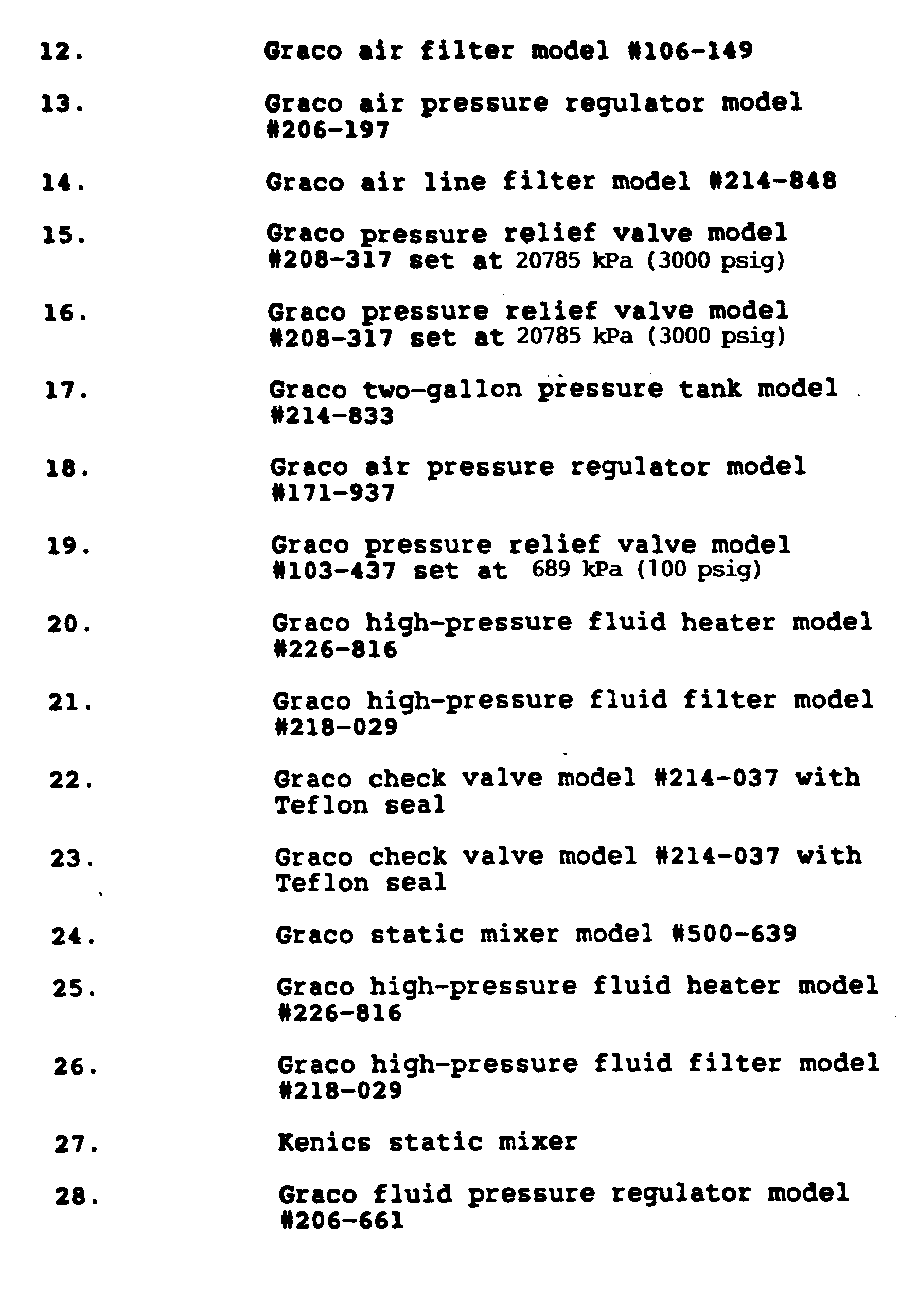

- The apparatus listed in Table 2 above was assembled as shown in the schematic representation contained in Figure 7. Rigid connections were made with Dekuron 6.35 mm (1/4-inch) diameter, 0.09 cm (0.036-inch) thick, seamless, welded, type 304 stainless steel hydraulic tubing ASTM A-269 with 34474 kPa (5000-psig) pressure rating, using Swagelock fittings. The pressure tank (17) was connected to the pump (8) using a Graco 9.525 mm (3/8-inch) static-free nylon high-pressure hose model #061-221 with 20684 kPa (3000-psi) pressure rating. All other flexible connections were made using Graco 6.35 mm (1/4-inch) static-free nylon high-pressure hoses modl #061-214 with 34474 kPa (5000-psi pressure rating. The spray gun (30) was connected to the Graco spray hose by using a Nordson 4.762 mm (3/16-inch) static-free nylon high-pressure whip hose model #828-036.
- The coating concentrate and carbon dioxide were pumped and proportioned using a Graco Variable Ratio Hydra-Cat Proportioning Pump unit (9). It proportions two fluids together at a given volume ratio by using two piston pumps that are slaved together. The piston rods for each pump are attached to opposite ends of a shaft that pivots up and down on a center fulcrum. The volume ratio is varied by sliding one pump along the shaft, which changes the stroke length. The pumps are driven on demand by an air motor (10). Pumping pressure is controlled by the air pressure that drives the air motor. The pumps are both double-acting; they pump on upstroke and downstroke. The primary pump (8) was used to pump the coating solution. It was of standard design, having one inlet and one outlet. It fills through a check valve at the bottom and discharges through a check valve at the top. A third check valve is located in the piston head, which allows liquid to flow from the bottom compartment to the top compartment when the piston is moving downward. This type of pump is designed to be used with low feed pressure, typically below 689.5 kPa (100 psi). The coating solution was supplied to the primary pump (8) from 7.57 l (two-gallon) pressure tank (17). After being pressurized in the pump to spray pressure, the solution was then heated in an electric heater (20) to reduce its viscosity (to aid mixing with carbon dioxide), filtered in a fluid filter (21) to remove particulates, and fed through a check valve (22) into the mix point with carbon dioxide. The secondary pump (7) on the proportioning Pump unit (9) was used to pump the liquid carbon dioxide. A double-acting piston pump (7) with a four-check-valve design was used because of the high vapor pressure of carbon dioxide. The pump has an inlet and an outlet on each side of the piston, and no flow occurs through the piston. The proportion of carbon dioxide pumped into the spray solution is varied by moving the pump along the moving shaft. Bone-dry-grade liquid carbon dioxide was supplied from cylinder (3) to the secondary pump. Air or gaseous carbon dioxide in the Hoke cylinder (3) was vented through valve (5) as the cylinder was filled. It is sometimes helpful to cool the liquid carbon dioxide by using a cooler heat exchanger (2) in order to lower the vapor pressure of carbon dioxide going into the Hoke Cylinder (3) to below the vapor pressure in cylinder (1). The Hoke cylinder (3) was mounted on a scale so that the amount of carbon dioxide in it could be weighed. After the Hoke cylinder (3) was filled with liquid carbon dioxide, it was pressurized with nitrogen from supply (6) to increase the pressure in the cyclinder (3) to above the vapor pressure of the carbon dioxide, in order to prevent cavitation in pump (7) caused by pressure drop across the inlet check valve during the suction stroke. After being pressurized to spray pressure in pump (7), the liquid carbon dioxide was fed unheated through a check valve (23) to the mix point with the coating solution. After the coating solution and carbon dioxide were proportioned together, the mixture was mixed in static mixer (24) and pumped on demand into a circulation loop, which circulates the mixture at spray pressure and temperature to or through the spray gun (30). The mixture was heated in an electric heater (25) to obtain the desired spray temperature and filtered in a fluid filter (26) to remove particulates. Fluid pressure regulator (28) was installed to lower the spray pressure below the pump pressure, if desired or to help maintain a constant spray pressure. A Jerguson site glass (29) was used to examine the phase condition of the mixture. Circulation flow in the circulation loop was obtained through the use of gear pump (32). By adjusting the valves which control the flow to and from the gear pump, the single-pass flow to the spray gun (30) could be obtained instead of a circulating flow.
- A clear acrylic coating concentrate having a total weight of 7430 grams was prepared by mixing the following materials:
4830 grams of Acryloid™ AT-400 Resin (Rohm & Haas Company), which contains 75% nonvolatile acrylic polymer dissolved in 25% methyl amyl ketone,
1510 grams of Cymel™ 323 Resin (American Cyanamid Company), which contains 80% nonvolatile melamine polymer dissolved in 20% isobutanol solvent,
742 grams of methyl amyl ketone,
348 grams of n-butanol solvent. - The coating concentrate contained 65.0% nonvolatile polymer solids and 35.0% volatile organic solvent. The pressure tank (17) was filled with the concentrate and pressurized with air to 446 kPa (50 psig).The Hoke cylinder (3) was filled with liquid carbon dioxide at room temperature and then pressurized to 7513 kPa (1075 psig) with compressed nitrogen. Pump (7) was placed along the pivoting shaft to give 60% of maximum piston displacement. The pumps were primed and the unit purged to produce a spray solution with steady composition. The circulation gear pump (32) was set to a rate of 30 revolutions per minute. Test panel (31) was mounted vertically within a spray hood in which atmospheric pressure existed. The spray pressure was adjusted to 12167 kPa (1750 psig)and the spray temperature to 60 C. A clear one-phase solution was seen in the Jerguson site glass (29). The liquid spray mixture contained 46% nonvolatile polymer solids, 24% volatile organic solvents, and 30% carbon dioxide. A liquid spray coating was applied to the Test panel (31). The test panel (31) was then baked in a convection oven for twenty minutes at a temperature of 120°C. The clear coating that was produced had an average thickness of 30.48 µm (1.2 mils), a distinctness of image of 80%, and a gloss of 90% (measured at an angle of 20 degrees from perpendicular).
- Although the invention has been illustrated by the preceding Example, it is not to be construed as being limited to the material employed therein, but rather, the invention relates to the generic area as hereinbefore disclosed. Various modifications and embodiments thereof can be made without departing from the scope thereof.
Claims (19)
- A process for the liquid spray application of coatings to a substrate wherein in a closed system a liquid mixture is formed containing at least one polymeric component (a) capable of forming a coating on a substrate and a component (b), and then spraying said liquid mixture onto a substrate to form a liquid coating thereon,
characterized in that
said component (b) comprises at least one supercritical fluid in at least an amount which when added to (a) is sufficient to render the viscosity of said mixture of (a) and (b) to a point suitable for spray application and optionally at least one active solvent (c) in which said at least one polymeric component (a) is soluble and which is at least partially miscible with the supercritical fluid, said solvent (c) being present in an amount such that the viscosity of the mixture of (a) and (c) is greater than that desirable for liquid spray application, and spraying said liquid mixture, forming droplets having an average diameter of 1 micron or greater, onto the substrate to form a liquid coating thereon. - The process of Claim 1 wherein the viscosity of the mixture of (a) and (b) is less than about 150 mPa·s.
- The process of Claim 1 wherein the viscosity of the mixture of (a) and (b) ranges from about 10 to about 100 mPa·s.
- The process of Claim 3 wherein the mixture of (a) and (b) ranges from about 20 to about 50 mPa·s.
- The process of Claim 1 wherein the at least one supercritical fluid comprises supercritical carbon dioxide.
- The process of Claim 1 wherein the viscosity of the mixture of (a), (b) and (c) is less than 150 mPa·s.
- The process of claim 6 wherein the viscosity of the mixture of (a), (b) and (c) ranges from 10 to 100 mPa·s.
- The process of claim 7 wherein the mixture of (a), (b) and (c) ranges from 20 to 50 mPa·s.
- The process of Claim 1 wherein said at least one polymeric component (a) is selected from the group consisting of enamels, varnishes, alkyl resins, polyesters, polyurethanes, cellulosic esters, lacquers and mixtures thereof.
- The process of Claim 1 wherein said at least one active solvent (c) is selected from the group consisting of unsaturated or aromatic hydrocarbons, ketones, esters, ethers, alcohols and mixtures thereof.
- The process of Claim 10 wherein said active solvent (c) is a glycol ether.
- The process of Claim 1 wherein the substrate is selected from the group consisting of metal, wood, glass, ceramic and plastic
- The process of Claim 1 further comprising curing the liquid coating on the substrate.
- The process of Claim 1 which comprises:(1) forming a liquid mixture in a closed system of:(A) at least one polymeric component (a) in an amount ranging from about 5 to about 65 wt.% based upon the total weight of (a), (b) and (c);(B) supercritical carbon dioxide fluid, in at least an amount which when added to (a) and (c) is sufficient to render the viscosity of said mixture of (a), (b) and (c) to a point ranging from about 10 to about 100 mPa·s; and(C) at least one active solvent (c) in an amount up to about 70 wt.% based upon the total weight of (a), (b) and (c) such that the viscosity of the mixture of (a) and (c) has a viscosity greater than about 150 mPa·s;and(2) spraying said liquid mixture onto a substrate to form a liquid coating thereon.
- The process of Claim 14 wherein the polymeric component (a) is present in amounts ranging from about 15 to about 55 wt.% based upon the total weight of (a), (b) and (c).
- The process of Claim 14 wherein the at least one active solvent (c) is present in amounts ranging from about 5 to about 50 wt.% based upon the total weight of (a), (b) and (c).
- The process of Claim 14 wherein the supercritical carbon dioxide fluid is present in amounts ranging from about 10 to about 60 wt.% based upon the total weight of (a), (b) and (c).
- The process of Claim 17 wherein the supercritical carbon dioxide fluid is present in amounts ranging from about 20 to 60 wt.% based upon the total weight of (a), (b) and (c).
- An apparatus for the accomplishment of the process as described in Claims 1 to 18, said apparatus comprised of,(1) means for supplying at least one polymeric component (a) capable of forming a continuous, adherent coating;(2) means for optionally supplying at least one active organic solvent (c) and(3) means for supplying supercritical carbon dioxide fluid and is characterized by:(4) means for forming a liquid mixture of components supplied from (1)-(3) and(5) means for spraying said liquid mixture forming droplets having an average diameter of 1 micron or greater onto a substrate to form a liquid coating thereon.
Priority Applications (1)
| Application Number | Priority Date | Filing Date | Title |
|---|---|---|---|
| AT87119281T ATE94782T1 (en) | 1987-12-21 | 1987-12-29 | USE OF SUPERCRITICAL LIQUIDS AS THINNERS WHEN SPRAYING COATS. |
Applications Claiming Priority (2)
| Application Number | Priority Date | Filing Date | Title |
|---|---|---|---|
| US13306887A | 1987-12-21 | 1987-12-21 | |
| US133068 | 1987-12-21 |
Publications (3)
| Publication Number | Publication Date |
|---|---|
| EP0321607A2 EP0321607A2 (en) | 1989-06-28 |
| EP0321607A3 EP0321607A3 (en) | 1990-09-26 |
| EP0321607B1 true EP0321607B1 (en) | 1993-09-22 |
Family
ID=22456864
Family Applications (1)
| Application Number | Title | Priority Date | Filing Date |
|---|---|---|---|
| EP87119281A Expired - Lifetime EP0321607B1 (en) | 1987-12-21 | 1987-12-29 | Supercritical fluids as diluents in liquid spray application of coatings |
Country Status (9)
| Country | Link |
|---|---|
| US (2) | US5027742A (en) |
| EP (1) | EP0321607B1 (en) |
| JP (1) | JPH0657336B2 (en) |
| KR (1) | KR930010197B1 (en) |
| AT (1) | ATE94782T1 (en) |
| AU (1) | AU613332B2 (en) |
| CA (1) | CA1271671A (en) |
| DE (1) | DE3787533T2 (en) |
| ES (1) | ES2043640T3 (en) |
Families Citing this family (160)
| Publication number | Priority date | Publication date | Assignee | Title |
|---|---|---|---|---|
| US5057342A (en) * | 1987-12-21 | 1991-10-15 | Union Carbide Chemicals And Plastics Technology Corporation | Methods and apparatus for obtaining a feathered spray when spraying liquids by airless techniques |
| US5106650A (en) * | 1988-07-14 | 1992-04-21 | Union Carbide Chemicals & Plastics Technology Corporation | Electrostatic liquid spray application of coating with supercritical fluids as diluents and spraying from an orifice |
| US5066522A (en) * | 1988-07-14 | 1991-11-19 | Union Carbide Chemicals And Plastics Technology Corporation | Supercritical fluids as diluents in liquid spray applications of adhesives |
| US5203843A (en) * | 1988-07-14 | 1993-04-20 | Union Carbide Chemicals & Plastics Technology Corporation | Liquid spray application of coatings with supercritical fluids as diluents and spraying from an orifice |
| US5108799A (en) * | 1988-07-14 | 1992-04-28 | Union Carbide Chemicals & Plastics Technology Corporation | Liquid spray application of coatings with supercritical fluids as diluents and spraying from an orifice |
| US5169687A (en) * | 1988-09-16 | 1992-12-08 | University Of South Florida | Supercritical fluid-aided treatment of porous materials |
| US5094892A (en) * | 1988-11-14 | 1992-03-10 | Weyerhaeuser Company | Method of perfusing a porous workpiece with a chemical composition using cosolvents |
| US5009367A (en) * | 1989-03-22 | 1991-04-23 | Union Carbide Chemicals And Plastics Technology Corporation | Methods and apparatus for obtaining wider sprays when spraying liquids by airless techniques |
| EP0388915B1 (en) * | 1989-03-22 | 1993-10-06 | Union Carbide Chemicals And Plastics Company, Inc. | Precursor coating compositions |
| CA2012698C (en) * | 1989-03-22 | 1996-12-03 | Kenneth Andrew Nielsen | Precursor coating compositions suitable for spraying with supercritical fluids as diluents |
| KR940011563B1 (en) * | 1989-09-27 | 1994-12-21 | 유니온 카바이드 케미칼즈 앤드 플라스틱스 캄파니 인코포레이티드 | Method and apparatus for metering and mixing non-compressible and compressible fluids |
| US5088443A (en) * | 1989-10-04 | 1992-02-18 | Nordson Corporation | Method and apparatus for spraying a liquid coating containing supercritical fluid or liquified gas |
| US5106659A (en) * | 1989-10-04 | 1992-04-21 | Nordson Corporation | Method and apparatus for spraying a liquid coating containing supercritical fluid or liquified gas |
| US5171089A (en) * | 1990-06-27 | 1992-12-15 | Union Carbide Chemicals & Plastics Technology Corporation | Semi-continuous method and apparatus for forming a heated and pressurized mixture of fluids in a predetermined proportion |
| US5098194A (en) * | 1990-06-27 | 1992-03-24 | Union Carbide Chemicals & Plastics Technology Corporation | Semi-continuous method and apparatus for forming a heated and pressurized mixture of fluids in a predetermined proportion |
| US5215253A (en) * | 1990-08-30 | 1993-06-01 | Nordson Corporation | Method and apparatus for forming and dispersing single and multiple phase coating material containing fluid diluent |
| US5171613A (en) * | 1990-09-21 | 1992-12-15 | Union Carbide Chemicals & Plastics Technology Corporation | Apparatus and methods for application of coatings with supercritical fluids as diluents by spraying from an orifice |
| AU642773B2 (en) * | 1990-10-16 | 1993-10-28 | Union Carbide Chemicals & Plastics Technology Corporation | Pressurized fluid composition and process for making same |
| US5306350A (en) * | 1990-12-21 | 1994-04-26 | Union Carbide Chemicals & Plastics Technology Corporation | Methods for cleaning apparatus using compressed fluids |
| JPH07121987B2 (en) * | 1990-12-21 | 1995-12-25 | ユニオン カーバイド ケミカルズ アンド プラスティックス カンパニー インコーポレイテッド | Method for lowering viscosity of liquid polymer compound-containing composition and liquid spray coating method |
| MX9201364A (en) * | 1991-03-27 | 1992-10-01 | Union Carbide Chem Plastic | CHEMICAL REACTION SUPPRESSION SYSTEM. |
| US5212229A (en) * | 1991-03-28 | 1993-05-18 | Union Carbide Chemicals & Plastics Technology Corporation | Monodispersed acrylic polymers in supercritical, near supercritical and subcritical fluids |
| US5105843A (en) * | 1991-03-28 | 1992-04-21 | Union Carbide Chemicals & Plastics Technology Corporation | Isocentric low turbulence injector |
| US5170727A (en) * | 1991-03-29 | 1992-12-15 | Union Carbide Chemicals & Plastics Technology Corporation | Supercritical fluids as diluents in combustion of liquid fuels and waste materials |
| US5178325A (en) * | 1991-06-25 | 1993-01-12 | Union Carbide Chemicals & Plastics Technology Corporation | Apparatus and methods for application of coatings with compressible fluids as diluent by spraying from an orifice |
| US5160766A (en) * | 1991-06-27 | 1992-11-03 | Akzo Coatings, Inc. | Process for applying a high solid coating composition using a high pressure airless spray |
| US5197800A (en) * | 1991-06-28 | 1993-03-30 | Nordson Corporation | Method for forming coating material formulations substantially comprised of a saturated resin rich phase |
| US5214925A (en) * | 1991-09-30 | 1993-06-01 | Union Carbide Chemicals & Plastics Technology Corporation | Use of liquified compressed gases as a refrigerant to suppress cavitation and compressibility when pumping liquified compressed gases |
| DE4133290A1 (en) * | 1991-10-08 | 1993-04-15 | Herberts Gmbh | METHOD FOR PRODUCING MULTILAYER LACQUERING USING RADICALLY AND / OR CATIONICALLY POLYMERIZABLE CLEAR VARNISHES |
| CA2082565A1 (en) * | 1991-11-12 | 1993-05-13 | John N. Argyropoulos | Polyester particularly suitable for use in coating compositions which are sprayed with compressed fluids as viscosity reducing diluents |
| KR930019861A (en) * | 1991-12-12 | 1993-10-19 | 완다 케이. 덴슨-로우 | Coating method using dense gas |
| DE4204611A1 (en) * | 1992-02-15 | 1993-08-19 | Herberts Gmbh | COATING AGENTS, THEIR USE AS CLEAR VARNISHES AND METHOD FOR THE PRODUCTION OF MULTILAYER LACQUERINGS |
| US5639441A (en) * | 1992-03-06 | 1997-06-17 | Board Of Regents Of University Of Colorado | Methods for fine particle formation |
| US5863612A (en) * | 1992-03-27 | 1999-01-26 | University North Carolina--Chapel Hill | Method of making fluoropolymers |
| US5688879A (en) * | 1992-03-27 | 1997-11-18 | The University Of North Carolina At Chapel Hill | Method of making fluoropolymers |
| EP0638095B1 (en) * | 1992-03-27 | 2002-08-07 | University Of North Carolina At Chapel Hill | Method of making fluoropolymers |
| WO1993019855A1 (en) * | 1992-03-31 | 1993-10-14 | Union Carbide Chemicals & Plastics Technology Corporation | Methods and apparatus for reducing air entrapment in spray application of coatings to a substrate |
| US5304390A (en) * | 1992-06-30 | 1994-04-19 | Union Carbide Chemicals & Plastics Technology Corporation | Supercritical ratio control system utilizing a sonic flow venturi and an air-driven positive displacement pump |
| US5378798A (en) * | 1992-07-10 | 1995-01-03 | Shell Oil Company | Composition and process for coating metallic substrates |
| US5290598A (en) * | 1992-09-23 | 1994-03-01 | Azko Coatings, Inc. | Process for applying a high solids coating composition using a high pressure airless spray |
| US5318225A (en) * | 1992-09-28 | 1994-06-07 | Union Carbide Chemicals & Plastics Technology Corporation | Methods and apparatus for preparing mixtures with compressed fluids |
| US5308648A (en) * | 1992-09-30 | 1994-05-03 | Union Carbide Chemicals & Plastics Technology Corporation | Spray application of plastics additives to polymers |
| US5290602A (en) * | 1992-10-19 | 1994-03-01 | Union Carbide Chemicals & Plastics Technology Corporation | Hindered-hydroxyl functional (meth) acrylate-containing copolymers particularly suitable for use in coating compositions which are sprayed with compressed fluids as viscosity reducing diluents |
| US5443796A (en) * | 1992-10-19 | 1995-08-22 | Nordson Corporation | Method and apparatus for preventing the formation of a solid precipitate in a coating material formulation |
| EP0669858A4 (en) * | 1992-11-02 | 1997-07-16 | Ferro Corp | Method of preparing coating materials. |
| US5290603A (en) * | 1992-12-18 | 1994-03-01 | Union Carbide Chemicals & Plastics Technology Corporation | Method for spraying polymeric compositions with reduced solvent emission and enhanced atomization |
| US5290604A (en) * | 1992-12-18 | 1994-03-01 | Union Carbide Chemicals & Plastics Technology Corporation | Methods and apparatus for spraying solvent-borne compositions with reduced solvent emission using compressed fluids and separating solvent |
| US5312862A (en) * | 1992-12-18 | 1994-05-17 | Union Carbide Chemicals & Plastics Technology Corporation | Methods for admixing compressed fluids with solvent-borne compositions comprising solid polymers |
| US5407267A (en) * | 1992-12-30 | 1995-04-18 | Nordson Corporation | Method and apparatus for forming and dispensing coating material containing multiple components |
| US5490726A (en) * | 1992-12-30 | 1996-02-13 | Nordson Corporation | Apparatus for proportioning two components to form a mixture |
| US6428844B1 (en) * | 1993-02-03 | 2002-08-06 | Rohm And Haas Company | Reduction of microfoam in a spray-applied waterborne composition |
| US5464154A (en) * | 1993-09-29 | 1995-11-07 | Union Carbide Chemicals & Plastics Technology Corporation | Methods for spraying polymeric compositions with compressed fluids and enhanced atomization |
| US5419487A (en) * | 1993-09-29 | 1995-05-30 | Union Carbide Chemicals & Plastics Technology Corporation | Methods for the spray application of water-borne coatings with compressed fluids |
| US5455076A (en) * | 1993-10-05 | 1995-10-03 | Union Carbide Chemicals & Plastics Technology Corporation | Method and apparatus for proportioning and mixing non-compressible and compressible fluids |
| US5407132A (en) * | 1993-10-20 | 1995-04-18 | Nordson Corporation | Method and apparatus for spraying viscous adhesives |
| US5520942A (en) * | 1994-02-15 | 1996-05-28 | Nabisco, Inc. | Snack food coating using supercritical fluid spray |
| US5415897A (en) * | 1994-03-23 | 1995-05-16 | The Boc Group, Inc. | Method of depositing solid substance on a substrate |
| DE4416282A1 (en) * | 1994-05-07 | 1995-11-09 | Herberts Gmbh | Binder composition, coating compositions containing it, their production and use |
| US5556471A (en) * | 1994-05-17 | 1996-09-17 | Nordson Corporation | Method and apparatus for dispensing foam materials |
| US5464661A (en) * | 1994-05-25 | 1995-11-07 | Davidson Textron Inc. | Reduced solvent island coating system |
| US5981696A (en) * | 1994-06-14 | 1999-11-09 | Herberts Gmbh | Process for preparing coating powder compositions and their use for making coatings |
| GB9413202D0 (en) * | 1994-06-30 | 1994-08-24 | Univ Bradford | Method and apparatus for the formation of particles |
| DE69427778T2 (en) * | 1994-11-02 | 2002-05-23 | Union Carbide Chem Plastic | METHOD AND APPARATUS FOR DOSING AND MIXING NON-COMPRESSIBLE AND COMPRESSIBLE LIQUIDS |
| US5716558A (en) * | 1994-11-14 | 1998-02-10 | Union Carbide Chemicals & Plastics Technology Corporation | Method for producing coating powders catalysts and drier water-borne coatings by spraying compositions with compressed fluids |
| MX9504934A (en) * | 1994-12-12 | 1997-01-31 | Morton Int Inc | Smooth thin film powder coatings. |
| AU5717296A (en) * | 1995-05-10 | 1996-11-29 | Ferro Corporation | Control system for processes using supercritical fluids |
| JPH09202963A (en) | 1995-08-25 | 1997-08-05 | Abcor Inc | Production of metallized island coated product without executing etching |
| US5756657A (en) * | 1996-06-26 | 1998-05-26 | University Of Massachusetts Lowell | Method of cleaning plastics using super and subcritical media |
| US6075074A (en) | 1996-07-19 | 2000-06-13 | Morton International, Inc. | Continuous processing of powder coating compositions |
| US6114414A (en) * | 1996-07-19 | 2000-09-05 | Morton International, Inc. | Continuous processing of powder coating compositions |
| US6583187B1 (en) | 1996-07-19 | 2003-06-24 | Andrew T. Daly | Continuous processing of powder coating compositions |
| US5766522A (en) * | 1996-07-19 | 1998-06-16 | Morton International, Inc. | Continuous processing of powder coating compositions |
| GB9703673D0 (en) * | 1997-02-21 | 1997-04-09 | Bradford Particle Design Ltd | Method and apparatus for the formation of particles |
| US5962564A (en) * | 1997-04-09 | 1999-10-05 | Xl Corporation | Water based high solids adhesives and adhesive application system including pressurized canister |
| US6344243B1 (en) | 1997-05-30 | 2002-02-05 | Micell Technologies, Inc. | Surface treatment |
| CA2291146C (en) | 1997-05-30 | 2008-09-09 | Micell Technologies | Surface treatment |
| US6287640B1 (en) | 1997-05-30 | 2001-09-11 | Micell Technologies, Inc. | Surface treatment of substrates with compounds that bind thereto |
| US6165560A (en) | 1997-05-30 | 2000-12-26 | Micell Technologies | Surface treatment |
| US6054103A (en) * | 1997-06-25 | 2000-04-25 | Ferro Corporation | Mixing system for processes using supercritical fluids |
| US5993747A (en) * | 1997-06-25 | 1999-11-30 | Ferro Corporation | Mixing system for processes using supercritical fluids |
| JP2001519237A (en) | 1997-10-10 | 2001-10-23 | ユニオン・カーバイド・ケミカルズ・アンド・プラスティックス・テクノロジー・コーポレイション | Spray application of additive composition to sheet material |
| US6127000A (en) * | 1997-10-10 | 2000-10-03 | North Carolina State University | Method and compositions for protecting civil infrastructure |
| US6120613A (en) * | 1998-04-30 | 2000-09-19 | Micell Technologies, Inc. | Carbon dioxide cleaning and separation systems |
| US6506259B1 (en) | 1998-04-30 | 2003-01-14 | Micell Technologies, Inc. | Carbon dioxide cleaning and separation systems |
| CA2332103A1 (en) * | 1998-05-11 | 1999-11-18 | Kenneth Look Hoy | High solids conductive coatings compositions suitable for electrostatic atomization application methods |
| GB9810559D0 (en) * | 1998-05-15 | 1998-07-15 | Bradford Particle Design Ltd | Method and apparatus for particle formation |
| US6048369A (en) * | 1998-06-03 | 2000-04-11 | North Carolina State University | Method of dyeing hydrophobic textile fibers with colorant materials in supercritical fluid carbon dioxide |
| US6221435B1 (en) | 1998-11-18 | 2001-04-24 | Union Carbide Chemicals & Plastics Technology Corporation | Method for the spray application of polymeric-containing liquid coating compositions using subcritical compressed fluids under choked flow spraying conditions |
| GB9915975D0 (en) * | 1999-07-07 | 1999-09-08 | Bradford Particle Design Ltd | Method for the formation of particles |
| DE19937465A1 (en) * | 1999-08-07 | 2001-02-08 | Volkswagen Ag | Adhesive composition, comprises adhesive and solvent that at least partially comprises super-critical carbon dioxide. |
| US6397421B1 (en) | 1999-09-24 | 2002-06-04 | Micell Technologies | Methods and apparatus for conserving vapor and collecting liquid carbon dioxide for carbon dioxide dry cleaning |
| US6314601B1 (en) * | 1999-09-24 | 2001-11-13 | Mcclain James B. | System for the control of a carbon dioxide cleaning apparatus |
| US6261326B1 (en) | 2000-01-13 | 2001-07-17 | North Carolina State University | Method for introducing dyes and other chemicals into a textile treatment system |
| WO2001062687A1 (en) | 2000-02-22 | 2001-08-30 | E.I. Dupont De Nemours And Company | A method for protection of stone with fluorinated urethane |
| US6773805B1 (en) | 2000-07-07 | 2004-08-10 | E. I. Du Pont De Nemours And Company | Method for protection of stone with substantially amorphous fluoropolymers |
| AU2001273186A1 (en) | 2000-07-07 | 2002-01-21 | E.I. Du Pont De Nemours And Company | A method for protection of stone with substantially amorphous fluoropolymers |
| US6723363B2 (en) | 2000-08-29 | 2004-04-20 | The Penn State Research Foundation | Coating foods and pharmaceuticals with an edible polymer using carbon dioxide |
| US6676710B2 (en) | 2000-10-18 | 2004-01-13 | North Carolina State University | Process for treating textile substrates |
| GB0027357D0 (en) | 2000-11-09 | 2000-12-27 | Bradford Particle Design Plc | Particle formation methods and their products |
| JP2004524948A (en) * | 2000-12-06 | 2004-08-19 | ウィルヘルム・テオドラス・ステファヌス・ハック | Patterned deposition using compressed carbon dioxide |
| US6790924B2 (en) * | 2001-02-22 | 2004-09-14 | E. I. Du Pont De Nemours And Company | Method for protection of stone with fluorinated urethane |
| US6656258B2 (en) | 2001-03-20 | 2003-12-02 | 3M Innovative Properties Company | Compositions comprising fluorinated silanes and compressed fluid CO2 |
| EP1401404B1 (en) * | 2001-05-30 | 2008-04-16 | Csir | Method of encapsulating an active substance |
| GB0117696D0 (en) * | 2001-07-20 | 2001-09-12 | Bradford Particle Design Plc | Particle information |
| GB0208742D0 (en) | 2002-04-17 | 2002-05-29 | Bradford Particle Design Ltd | Particulate materials |
| US6655796B2 (en) * | 2001-12-20 | 2003-12-02 | Eastman Kodak Company | Post-print treatment for ink jet printing apparatus |
| US6832699B2 (en) * | 2002-02-22 | 2004-12-21 | Terrasimco Inc. | Direct pressure apparatus and method for dispensing coatings |
| AU2003215357A1 (en) * | 2002-02-22 | 2003-09-09 | Terrasimco Inc. | Bladder-based apparatus and method for dispensing coatings |
| US7582284B2 (en) * | 2002-04-17 | 2009-09-01 | Nektar Therapeutics | Particulate materials |
| GB0216562D0 (en) * | 2002-04-25 | 2002-08-28 | Bradford Particle Design Ltd | Particulate materials |
| US9339459B2 (en) | 2003-04-24 | 2016-05-17 | Nektar Therapeutics | Particulate materials |
| US7220457B2 (en) * | 2002-06-06 | 2007-05-22 | Anderson Steven R | Air atomizing assembly and method and system of applying an air atomized material |
| CA2447743C (en) * | 2002-10-31 | 2012-05-22 | Honda Motor Co., Ltd. | Fluid balanced paint system |
| EP1624862B1 (en) * | 2003-05-08 | 2014-12-31 | Nektar Therapeutics | Particulate materials |
| ATE346852T1 (en) * | 2003-08-21 | 2006-12-15 | 3M Innovative Properties Co | PERFLUORPOLYETHERAMID BONDED PHOSPHONATES, PHOSPHATES AND DERIVATIVES THEREOF |
| WO2005022603A2 (en) * | 2003-09-02 | 2005-03-10 | Integral Technologies, Inc. | Low cost conductive containers manufactured from conductive loaded resin-based materials |
| US7652115B2 (en) * | 2003-09-08 | 2010-01-26 | 3M Innovative Properties Company | Fluorinated polyether isocyanate derived silane compositions |
| JP2007505136A (en) * | 2003-09-10 | 2007-03-08 | マツプ・フアーマシユーテイカルズ・インコーポレーテツド | Aerosol formulation for delivering dihydroergotamine to systemic circulation by pulmonary inhalation |
| US7141537B2 (en) * | 2003-10-30 | 2006-11-28 | 3M Innovative Properties Company | Mixture of fluorinated polyethers and use thereof as surfactant |
| US7803894B2 (en) | 2003-12-05 | 2010-09-28 | 3M Innovatie Properties Company | Coating compositions with perfluoropolyetherisocyanate derived silane and alkoxysilanes |
| US9257302B1 (en) | 2004-03-25 | 2016-02-09 | Novellus Systems, Inc. | CVD flowable gap fill |
| US7524735B1 (en) | 2004-03-25 | 2009-04-28 | Novellus Systems, Inc | Flowable film dielectric gap fill process |
| US7223445B2 (en) * | 2004-03-31 | 2007-05-29 | Eastman Kodak Company | Process for the deposition of uniform layer of particulate material |
| US20050218076A1 (en) * | 2004-03-31 | 2005-10-06 | Eastman Kodak Company | Process for the formation of particulate material |
| US7220456B2 (en) * | 2004-03-31 | 2007-05-22 | Eastman Kodak Company | Process for the selective deposition of particulate material |
| US7909263B2 (en) * | 2004-07-08 | 2011-03-22 | Cube Technology, Inc. | Method of dispersing fine particles in a spray |
| JP2008529591A (en) * | 2005-02-04 | 2008-08-07 | ザ プロクター アンド ギャンブル カンパニー | Absorbent structure with improved water-absorbing material |
| CA2626603C (en) * | 2005-10-17 | 2014-07-15 | National Research Council Of Canada | Reactive spray formation of coatings and powders |
| ATE477291T1 (en) * | 2005-10-25 | 2010-08-15 | Evonik Degussa Gmbh | PREPARATIONS COMPRISING HYPERBRANCHED POLYMERS |
| JP4936794B2 (en) * | 2006-05-31 | 2012-05-23 | 中国電力株式会社 | Oxygen-curing coating device |
| US9245739B2 (en) | 2006-11-01 | 2016-01-26 | Lam Research Corporation | Low-K oxide deposition by hydrolysis and condensation |
| BRPI0717017A2 (en) * | 2006-12-01 | 2013-10-08 | Teijen Fibers Ltd | METHOD AND APPARATUS FOR GIVING A FUNCTION TO A POLYMER ARTICLE |
| EP2425819A1 (en) | 2007-02-11 | 2012-03-07 | MAP Pharmaceuticals Inc | Method of therapeutic administration of dhe to enable rapid relief of migraine while minimizing side effect profile |
| US7703705B2 (en) * | 2007-02-16 | 2010-04-27 | Nordson Corporation | Apparatus and method for dispensing a mixture of a gas and a fluid material |
| EP1982698A1 (en) * | 2007-04-18 | 2008-10-22 | Evonik Degussa GmbH | Preparations for controlled release of natural bioactive materials |
| US7762647B2 (en) * | 2007-09-25 | 2010-07-27 | Eastman Kodak Company | MEMS printhead based compressed fluid printing system |
| CA2653188C (en) * | 2009-02-06 | 2014-04-22 | Honda Motor Co., Ltd. | Circulating paint systems |
| DE102009013133A1 (en) * | 2009-03-13 | 2010-09-16 | Linde Ag | Method and device for gassing |
| JP5429929B2 (en) * | 2009-03-31 | 2014-02-26 | 独立行政法人産業技術総合研究所 | Method and apparatus for coating one- and two-component paints using carbon dioxide |
| JP5429928B2 (en) * | 2009-03-31 | 2014-02-26 | 独立行政法人産業技術総合研究所 | Carbon dioxide coating method and apparatus |
| WO2010113489A1 (en) | 2009-03-31 | 2010-10-07 | 独立行政法人産業技術総合研究所 | Carbon dioxide coating method and device therefor |
| WO2010151804A1 (en) * | 2009-06-26 | 2010-12-29 | Map Pharmaceuticals, Inc. | Administration of dihydroergotamine mesylate particles using a metered dose inhaler |
| US8278224B1 (en) * | 2009-09-24 | 2012-10-02 | Novellus Systems, Inc. | Flowable oxide deposition using rapid delivery of process gases |
| JP5568801B2 (en) * | 2010-10-19 | 2014-08-13 | 独立行政法人産業技術総合研究所 | Carbon dioxide coating method and apparatus |
| JP5660605B2 (en) * | 2010-10-19 | 2015-01-28 | 独立行政法人産業技術総合研究所 | Method and apparatus for continuous mixing of high pressure carbon dioxide and high viscosity organic fluid |
| JP5699307B2 (en) * | 2010-10-20 | 2015-04-08 | 宮城県 | Film formation method |
| US8685867B1 (en) | 2010-12-09 | 2014-04-01 | Novellus Systems, Inc. | Premetal dielectric integration process |
| US9719169B2 (en) | 2010-12-20 | 2017-08-01 | Novellus Systems, Inc. | System and apparatus for flowable deposition in semiconductor fabrication |
| US9808030B2 (en) | 2011-02-11 | 2017-11-07 | Grain Processing Corporation | Salt composition |
| US8846536B2 (en) | 2012-03-05 | 2014-09-30 | Novellus Systems, Inc. | Flowable oxide film with tunable wet etch rate |
| JP2013230448A (en) * | 2012-05-02 | 2013-11-14 | Ricoh Co Ltd | Method for producing particle and particle |
| US9847222B2 (en) | 2013-10-25 | 2017-12-19 | Lam Research Corporation | Treatment for flowable dielectric deposition on substrate surfaces |
| US10049921B2 (en) | 2014-08-20 | 2018-08-14 | Lam Research Corporation | Method for selectively sealing ultra low-k porous dielectric layer using flowable dielectric film formed from vapor phase dielectric precursor |
| JP5972435B1 (en) * | 2015-07-29 | 2016-08-17 | 長瀬産業株式会社 | Coating liquid composition, method for producing coating liquid composition, and composition for preparing coating liquid composition |
| US11192128B2 (en) * | 2015-09-17 | 2021-12-07 | Cnh Industrial America Llc | Independent nozzle injection control system for sprayers |
| US10388546B2 (en) | 2015-11-16 | 2019-08-20 | Lam Research Corporation | Apparatus for UV flowable dielectric |
| US9916977B2 (en) | 2015-11-16 | 2018-03-13 | Lam Research Corporation | Low k dielectric deposition via UV driven photopolymerization |
| JP6755525B2 (en) | 2016-02-19 | 2020-09-16 | 東洋紡株式会社 | UV curable paint coating method and UV curable film manufacturing method |
| JP5923677B1 (en) | 2016-03-09 | 2016-05-24 | 長瀬産業株式会社 | Coating liquid composition, coating film forming method, coating liquid composition manufacturing method, coating liquid composition manufacturing apparatus, and carbon dioxide-containing coating liquid composition preparation composition |
| JP6130016B1 (en) * | 2016-04-20 | 2017-05-17 | 昭和電工ガスプロダクツ株式会社 | Coating apparatus, coating method and method for producing mixture |
Family Cites Families (17)
| Publication number | Priority date | Publication date | Assignee | Title |
|---|---|---|---|---|
| DE2242844A1 (en) * | 1972-08-31 | 1974-04-11 | Wolfgang Joachim Guettner | Zein-based aerosol spray - contg carbon dioxide propellant dissolved in solvent (mixt) for zein |
| US4124528A (en) * | 1974-10-04 | 1978-11-07 | Arthur D. Little, Inc. | Process for regenerating adsorbents with supercritical fluids |
| DE2603664A1 (en) * | 1976-01-31 | 1977-08-04 | Abova Gmbh Verpackungs Und Spe | Aerosol container charging system - uses carbon dioxide heated to supercritical temperature at constant pressure for blowing in |
| US4189914A (en) * | 1978-06-19 | 1980-02-26 | The United States Of America As Represented By The Administrator Of The National Aeronautics And Space Administration | Supercritical fuel injection system |
| DE2853066A1 (en) * | 1978-12-08 | 1980-06-26 | August Prof Dipl Phys D Winsel | Monomolecular or very thin coating prodn. on porous material - by contact with supercritical gas contg. solid or liq. coating material in soln. |
| JPS5584328A (en) * | 1978-12-20 | 1980-06-25 | Mitsui Petrochem Ind Ltd | Treatment of aqueous dispersion |
| US4375387A (en) * | 1979-09-28 | 1983-03-01 | Critical Fluid Systems, Inc. | Apparatus for separating organic liquid solutes from their solvent mixtures |
| JPH0235792B2 (en) * | 1982-03-31 | 1990-08-13 | Nippon Oxygen Co Ltd | FUNMUYOSETSUCHAKUZAISOSEIBUTSU |
| JPS5916703A (en) * | 1982-07-20 | 1984-01-27 | ア−ス製薬株式会社 | Wood degradation preventive agent composition and method of preventing degradation of wood |
| US4582731A (en) * | 1983-09-01 | 1986-04-15 | Battelle Memorial Institute | Supercritical fluid molecular spray film deposition and powder formation |
| US4734451A (en) * | 1983-09-01 | 1988-03-29 | Battelle Memorial Institute | Supercritical fluid molecular spray thin films and fine powders |
| US4734227A (en) * | 1983-09-01 | 1988-03-29 | Battelle Memorial Institute | Method of making supercritical fluid molecular spray films, powder and fibers |
| US4619735A (en) * | 1985-02-13 | 1986-10-28 | Melamine Chemicals, Inc. | Method of retarding paper degradation with time by treatment with melamine, and method of producing ageing-resistant paper coated with melamine |
| US4677168A (en) * | 1985-03-29 | 1987-06-30 | Hoy Kenneth L | Water borne high solids coating compositions |
| CA1255066A (en) * | 1985-10-02 | 1989-06-06 | Robert J. Huddleston | Method and apparatus for foaming high viscosity polymer materials |
| US4737384A (en) * | 1985-11-01 | 1988-04-12 | Allied Corporation | Deposition of thin films using supercritical fluids |
| JPH06102124B2 (en) * | 1985-12-27 | 1994-12-14 | 日本分光工業株式会社 | Separation and collection method of sample by supercritical fluid |
-
1987
- 1987-12-29 EP EP87119281A patent/EP0321607B1/en not_active Expired - Lifetime
- 1987-12-29 DE DE87119281T patent/DE3787533T2/en not_active Expired - Fee Related
- 1987-12-29 ES ES87119281T patent/ES2043640T3/en not_active Expired - Lifetime
- 1987-12-29 AT AT87119281T patent/ATE94782T1/en not_active IP Right Cessation
- 1987-12-30 CA CA000555651A patent/CA1271671A/en not_active Expired - Lifetime
- 1987-12-30 AU AU83138/87A patent/AU613332B2/en not_active Ceased
-
1988
- 1988-01-05 JP JP63000168A patent/JPH0657336B2/en not_active Expired - Fee Related
- 1988-01-11 KR KR1019880000121A patent/KR930010197B1/en not_active IP Right Cessation
-
1989
- 1989-08-24 US US07/397,974 patent/US5027742A/en not_active Expired - Lifetime
- 1989-10-04 US US07/418,820 patent/US4923720A/en not_active Expired - Lifetime
Also Published As
| Publication number | Publication date |
|---|---|
| DE3787533D1 (en) | 1993-10-28 |
| US4923720A (en) | 1990-05-08 |
| US5027742A (en) | 1991-07-02 |
| EP0321607A2 (en) | 1989-06-28 |
| EP0321607A3 (en) | 1990-09-26 |
| ES2043640T3 (en) | 1994-01-01 |
| ATE94782T1 (en) | 1993-10-15 |
| KR890011630A (en) | 1989-08-21 |
| AU8313887A (en) | 1989-06-22 |
| DE3787533T2 (en) | 1994-01-20 |
| JPH0657336B2 (en) | 1994-08-03 |
| CA1271671A (en) | 1990-07-17 |
| JPH01258770A (en) | 1989-10-16 |
| AU613332B2 (en) | 1991-08-01 |
| KR930010197B1 (en) | 1993-10-15 |
Similar Documents
| Publication | Publication Date | Title |
|---|---|---|
| EP0321607B1 (en) | Supercritical fluids as diluents in liquid spray application of coatings | |
| EP0350910B1 (en) | Liquid spray application of coatings with supercritical fluids as diluents and spraying from an orifice | |
| EP0388923B1 (en) | Precursor coating compositions | |
| EP0420181A2 (en) | Method and apparatus for metering and mixing noncompressible and compressible fluids | |
| US5211342A (en) | Electrostatic liquid spray application of coatings with supercritical fluids as diluents and spraying from an orifice | |
| US5466490A (en) | Precursor coating compositions containing water and an organic coupling solvent suitable for spraying with supercritical fluids as diluents | |
| US5057342A (en) | Methods and apparatus for obtaining a feathered spray when spraying liquids by airless techniques | |
| EP0388916A1 (en) | Supercritical fluids as diluents in liquid spray applications of adhesives | |
| US5141156A (en) | Methods and apparatus for obtaining a feathered spray when spraying liquids by airless techniques | |
| EP0607587B1 (en) | Methods for admixing compressed fluids with solvent-borne compositions comprising solid polymers | |
| CA1336662C (en) | Electrostatic liquid spray application of coatings with supercritical fluids as diluents and spraying from an orifice | |
| EP0388928A1 (en) | Method and apparatus for obtaining wider sprays | |
| US5203843A (en) | Liquid spray application of coatings with supercritical fluids as diluents and spraying from an orifice | |
| CA2058169C (en) | Subcritical compressed fluids as viscosity reducing diluents for transportable compositions |
Legal Events
| Date | Code | Title | Description |
|---|---|---|---|
| PUAI | Public reference made under article 153(3) epc to a published international application that has entered the european phase |
Free format text: ORIGINAL CODE: 0009012 |
|
| AK | Designated contracting states |
Kind code of ref document: A2 Designated state(s): AT DE ES FR GB IT NL |
|
| PUAL | Search report despatched |
Free format text: ORIGINAL CODE: 0009013 |
|
| AK | Designated contracting states |
Kind code of ref document: A3 Designated state(s): AT DE ES FR GB IT NL |
|
| 17P | Request for examination filed |
Effective date: 19901022 |
|
| 17Q | First examination report despatched |
Effective date: 19910813 |
|
| GRAA | (expected) grant |
Free format text: ORIGINAL CODE: 0009210 |
|
| AK | Designated contracting states |
Kind code of ref document: B1 Designated state(s): AT DE ES FR GB IT NL |
|
| REF | Corresponds to: |
Ref document number: 94782 Country of ref document: AT Date of ref document: 19931015 Kind code of ref document: T |
|
| REF | Corresponds to: |
Ref document number: 3787533 Country of ref document: DE Date of ref document: 19931028 |
|
| ITF | It: translation for a ep patent filed |
Owner name: ING. C. GREGORJ S.P.A. |
|
| ET | Fr: translation filed | ||
| REG | Reference to a national code |
Ref country code: ES Ref legal event code: FG2A Ref document number: 2043640 Country of ref document: ES Kind code of ref document: T3 |
|
| PLBE | No opposition filed within time limit |
Free format text: ORIGINAL CODE: 0009261 |
|
| STAA | Information on the status of an ep patent application or granted ep patent |
Free format text: STATUS: NO OPPOSITION FILED WITHIN TIME LIMIT |
|
| 26N | No opposition filed | ||
| REG | Reference to a national code |
Ref country code: GB Ref legal event code: IF02 |
|
| PGFP | Annual fee paid to national office [announced via postgrant information from national office to epo] |
Ref country code: FR Payment date: 20040825 Year of fee payment: 18 Ref country code: DE Payment date: 20040825 Year of fee payment: 18 |
|
| PGFP | Annual fee paid to national office [announced via postgrant information from national office to epo] |
Ref country code: NL Payment date: 20040827 Year of fee payment: 18 |
|
| PGFP | Annual fee paid to national office [announced via postgrant information from national office to epo] |
Ref country code: GB Payment date: 20041001 Year of fee payment: 18 |
|
| PGFP | Annual fee paid to national office [announced via postgrant information from national office to epo] |
Ref country code: AT Payment date: 20041019 Year of fee payment: 18 |
|
| PGFP | Annual fee paid to national office [announced via postgrant information from national office to epo] |
Ref country code: ES Payment date: 20041213 Year of fee payment: 18 |
|
| PG25 | Lapsed in a contracting state [announced via postgrant information from national office to epo] |
Ref country code: IT Free format text: LAPSE BECAUSE OF NON-PAYMENT OF DUE FEES;WARNING: LAPSES OF ITALIAN PATENTS WITH EFFECTIVE DATE BEFORE 2007 MAY HAVE OCCURRED AT ANY TIME BEFORE 2007. THE CORRECT EFFECTIVE DATE MAY BE DIFFERENT FROM THE ONE RECORDED. Effective date: 20051229 Ref country code: GB Free format text: LAPSE BECAUSE OF NON-PAYMENT OF DUE FEES Effective date: 20051229 Ref country code: AT Free format text: LAPSE BECAUSE OF NON-PAYMENT OF DUE FEES Effective date: 20051229 |
|
| PG25 | Lapsed in a contracting state [announced via postgrant information from national office to epo] |
Ref country code: ES Free format text: LAPSE BECAUSE OF NON-PAYMENT OF DUE FEES Effective date: 20051230 |
|
| PG25 | Lapsed in a contracting state [announced via postgrant information from national office to epo] |
Ref country code: NL Free format text: LAPSE BECAUSE OF NON-PAYMENT OF DUE FEES Effective date: 20060701 Ref country code: DE Free format text: LAPSE BECAUSE OF NON-PAYMENT OF DUE FEES Effective date: 20060701 |
|
| GBPC | Gb: european patent ceased through non-payment of renewal fee |
Effective date: 20051229 |
|
| PG25 | Lapsed in a contracting state [announced via postgrant information from national office to epo] |
Ref country code: FR Free format text: LAPSE BECAUSE OF NON-PAYMENT OF DUE FEES Effective date: 20060831 |
|
| NLV4 | Nl: lapsed or anulled due to non-payment of the annual fee |
Effective date: 20060701 |
|
| REG | Reference to a national code |
Ref country code: FR Ref legal event code: ST Effective date: 20060831 |
|
| REG | Reference to a national code |
Ref country code: ES Ref legal event code: FD2A Effective date: 20051230 |