EP0321358A1 - Dispositif de prélèvement de sang - Google Patents
Dispositif de prélèvement de sang Download PDFInfo
- Publication number
- EP0321358A1 EP0321358A1 EP88403221A EP88403221A EP0321358A1 EP 0321358 A1 EP0321358 A1 EP 0321358A1 EP 88403221 A EP88403221 A EP 88403221A EP 88403221 A EP88403221 A EP 88403221A EP 0321358 A1 EP0321358 A1 EP 0321358A1
- Authority
- EP
- European Patent Office
- Prior art keywords
- blood
- piston
- main body
- sampling
- air
- Prior art date
- Legal status (The legal status is an assumption and is not a legal conclusion. Google has not performed a legal analysis and makes no representation as to the accuracy of the status listed.)
- Granted
Links
Images

Classifications
-
- A—HUMAN NECESSITIES
- A61—MEDICAL OR VETERINARY SCIENCE; HYGIENE
- A61B—DIAGNOSIS; SURGERY; IDENTIFICATION
- A61B5/00—Measuring for diagnostic purposes; Identification of persons
- A61B5/15—Devices for taking samples of blood
- A61B5/153—Devices specially adapted for taking samples of venous or arterial blood, e.g. with syringes
-
- A—HUMAN NECESSITIES
- A61—MEDICAL OR VETERINARY SCIENCE; HYGIENE
- A61B—DIAGNOSIS; SURGERY; IDENTIFICATION
- A61B5/00—Measuring for diagnostic purposes; Identification of persons
- A61B5/15—Devices for taking samples of blood
- A61B5/150007—Details
- A61B5/150015—Source of blood
- A61B5/15003—Source of blood for venous or arterial blood
-
- A—HUMAN NECESSITIES
- A61—MEDICAL OR VETERINARY SCIENCE; HYGIENE
- A61B—DIAGNOSIS; SURGERY; IDENTIFICATION
- A61B5/00—Measuring for diagnostic purposes; Identification of persons
- A61B5/15—Devices for taking samples of blood
- A61B5/150007—Details
- A61B5/150206—Construction or design features not otherwise provided for; manufacturing or production; packages; sterilisation of piercing element, piercing device or sampling device
- A61B5/150213—Venting means
-
- A—HUMAN NECESSITIES
- A61—MEDICAL OR VETERINARY SCIENCE; HYGIENE
- A61B—DIAGNOSIS; SURGERY; IDENTIFICATION
- A61B5/00—Measuring for diagnostic purposes; Identification of persons
- A61B5/15—Devices for taking samples of blood
- A61B5/150007—Details
- A61B5/150206—Construction or design features not otherwise provided for; manufacturing or production; packages; sterilisation of piercing element, piercing device or sampling device
- A61B5/150236—Pistons, i.e. cylindrical bodies that sit inside the syringe barrel, typically with an air tight seal, and slide in the barrel to create a vacuum or to expel blood
-
- A—HUMAN NECESSITIES
- A61—MEDICAL OR VETERINARY SCIENCE; HYGIENE
- A61B—DIAGNOSIS; SURGERY; IDENTIFICATION
- A61B5/00—Measuring for diagnostic purposes; Identification of persons
- A61B5/15—Devices for taking samples of blood
- A61B5/150007—Details
- A61B5/150351—Caps, stoppers or lids for sealing or closing a blood collection vessel or container, e.g. a test-tube or syringe barrel
-
- A—HUMAN NECESSITIES
- A61—MEDICAL OR VETERINARY SCIENCE; HYGIENE
- A61B—DIAGNOSIS; SURGERY; IDENTIFICATION
- A61B5/00—Measuring for diagnostic purposes; Identification of persons
- A61B5/15—Devices for taking samples of blood
- A61B5/150007—Details
- A61B5/150374—Details of piercing elements or protective means for preventing accidental injuries by such piercing elements
- A61B5/150381—Design of piercing elements
- A61B5/150389—Hollow piercing elements, e.g. canulas, needles, for piercing the skin
-
- A—HUMAN NECESSITIES
- A61—MEDICAL OR VETERINARY SCIENCE; HYGIENE
- A61B—DIAGNOSIS; SURGERY; IDENTIFICATION
- A61B5/00—Measuring for diagnostic purposes; Identification of persons
- A61B5/15—Devices for taking samples of blood
- A61B5/150007—Details
- A61B5/150374—Details of piercing elements or protective means for preventing accidental injuries by such piercing elements
- A61B5/150381—Design of piercing elements
- A61B5/150503—Single-ended needles
Definitions
- the present invention relates to a device for collecting and storing blood for the purpose of gas analysis.
- the present invention relates more particularly to a device which reduces contamination of the blood with ambient air, which reduces the stress forces which can destroy the internal gas balance of the blood and which reduces the coagulability of the blood in situ.
- the object of the invention is and performance to overcome the defects and problems of the systems described above.
- the sampling device is characterized, according to the invention, in that it comprises an inert piston and not accessible by the operator, reducing the gas exchange between air and blood, and a porous air-tight and blood-tight filter guaranteeing minimal contamination of the sample taken.
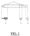
- the system relating to the invention consists of a main body (1 Fig. 1) acting as a container of blood, an inert cylindrical piston (2 Fig. 1), a cylindrical plug porous in air and blood-tight (3 Fig. 1), and a plastic stopper (4 Fig. 1).
- a main body (1 Fig. 1) acting as a container of blood an inert cylindrical piston (2 Fig. 1), a cylindrical plug porous in air and blood-tight (3 Fig. 1), and a plastic stopper (4 Fig. 1).
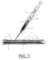
- the anterior part the part connecting to the sampling needle (5 Fig. 3) or part in which the blood enters the system
- posterior part T Fig. 2 as the opposite and terminal part of the system.
- the main body (1) is made up of five characteristic parts.
- the front part (A Fig. 2) coaxial with the system, has an outside diameter allowing the mounting of a sampling needle, and an inside diameter of at least fifteen tenths of a millimeter. This minimum internal diameter is necessary for the use of the invention on gas analyzers of the INSTRUMENTATION LABORATORY and RADIOMETTER brand, for example.
- the inert piston (2) is formed of two characteristic parts: a main part and an anterior part (P) coaxial with the main part (0 Fig. 2).
- the front part (P Fig. 2) of the piston (2) has a diameter smaller than its main part (o), and also slightly less than the internal diameter of the front part (A) of the main body (1).
- this cylindrical part (P) follows the shape of the front part (A Fig. 2) of the main body (1), thus reducing the dead volume at the orifice of the sampling system.
- This male-female type arrangement (Fig. 2) has the advantage of reducing air / blood contact, thereby reducing contamination of the blood when it enters the system. This device is fundamental in the development of the invention.
- the porous filter (3) placed at the level of the stop (F Fig. 2) in the rear part (T) of the main body (1) has the property of allowing air to pass through and of remaining blood tight. It allows the compressed air in the chamber (C Fig.2) of the main body (1) to escape until the piston (2) reaches the stop on the narrowed part (F Fig.2) of the main body (1) thus playing a regulatory role during the ascent of the blood sample.
- This filter also creates a barrier reducing the area of gas exchange between the blood contained in the central part (C) and the ambient air located in the central part (C) and the ambient air located in the rear part (T). of the main body (1).
- This filter will have a size and porosity adapted to the arterial pressure of the blood collected.
- the plug (4) is installed at the end of the rear part (T) of the main body (1).
- a hole (G) located on the rear part (T) of the main body (1) makes it possible to depressurize this rear part when the plug (4) is put in place.
- This hole (G) will be obstructed at the end of the travel of the plug (4).
- This plug reduces the air volume of the posterior chamber (T) of the part main (1) in order to limit contamination over time of blood by air.
- the length sizes of the rear part (T) of the main body (1) and that of the filter (3) are adjusted to allow the plug (4) to be adapted so that the latter, once in place, comes position against the filter (3). It also allows easy transport of the system, from the sampling site to the analysis site, without the blood being able to come out through the front part (A) of the main body (1) in a vertical position.
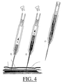
- the protocol for using the system develops different phases: a first phase of adaptation of a sterile needle (5 Fig.3) on the anterior part (A) of the main body (1), a second phase (f1 Fig.4 ) penetration of the needle into the patient's body (7 Fig. 3) up to the artery where the blood is to be drawn (8 Fig. 3), a third phase (f2 Fig. 4) of blood rising in the sampling system, the blood pressure causing a push (M Fig. 3) of the piston (2) up to the part forming a stop (F), a fourth phase (f3 Fig. 4) of withdrawal of the needle , and finally a final phase (f3 Fig.4) of fitting the plug (4) and a conventional needle protection system.
- the invention has the fundamental advantage of not offering any possibility of reinjection to the patient of the contents of the chamber (C) of the main body (1).
- This advantage is indeed decisive in the cost of manufacturing the system since the latter does not need to be sterile, which on the other hand avoids the administrative constraints relating to the sale of syringes.
- the invention finally, made for the part of the main body (1) and that of the piston (2) of non-wettable polypropylene type material does not trigger the coagulation of the blood collected. This material is also translucent, which allows a visualization of the rise of blood in the system.
- the system relating to the invention will be used as a capillary sampling mode on the various gas analyzers on the market, that is to say that the blood will be aspirated by the analyzer during a measurement of the sample.
Abstract
Description
- La présente invention concerne un dispositif permettant le prélèvement et la conservation du sang en vue d'en effectuer l'analyse gazométrique. La présente invention concerne plus particulièrement un dispositif qui réduit la contamination du sang avec l'air ambiant, qui réduit les forces de contraintes pouvant destructurer l'équilibre gazeux interne du sang et qui réduit la coagulabilité du sang in situ.
- De nombreux procédés selon l'art antérieur posent problèmes. Parmi ceux-ci, il existe ceux qui utilisent la forme conventionnelle de seringue avec un corps principal faisant effet de réservoir et un piston pour maitriser la quantité du prélèvement. Ce système, outre qu'il utilise une quantité importante de sang, posséde une surface d'échange avec l'air importante entraînant une contamination du sang prélevé. Le désavantage majeur d'un tel système reste cependant la possibilité, de par la présence et la fonction même du piston, de réinjection par l'opérateur de produits dangereux tels que les agents anticoagulants contenus généralement dans la seringue.
- D'autres systèmes, selon l'art antérieur, utilisent une forme capillaire. Cette forme permet de recueillir une quantité plus faible de sang. De plus l'échange surfacique air/sang est diminué de par le faible diamètre du capillaire. Ces systèmes ont cependant les désavantages d'utiliser des capillaires en verre qui, de par le matériau même, activent la coagulabilité du sang (phénomène du 'glass-effect'), d'être peu pratiques à transporter et à conserver, et de parfois ne prélever qu'une trop faible quantité de sang pour permettre d'effectuer ultérieurement plusieurs analyses.
- L'invention a pour but et performances de surmonter les défauts et problèmes des systèmes décrits précédemment. Le dispositif de prélèvement se caractérise, selon l'invention, en ce qu'il comporte un piston inerte et non accesible par l'opérateur, réduisant l'échange gazeux entre l'air et le sang, et un filtre poreux à l'air et étanche au sang garantissant une contamination minimale de l'échantillon prélevé.
- Le système relatif à l'invention se compose d'un corps principal (1 Fig.1) faisant effet de contenant du sang, d'un piston cylindrique inerte (2 Fig.1), d'un bouchon cylindrique poreux à l'air et étanche au sang (3 Fig.1), et d'un bouchon plastique (4 Fig. 1). Nous définirons arbitrairement dans la description de l'invention, ci-dessous, comme partie antérieure (A Fig.2) la partie se raccordant à l'aiguille de prélèvement (5 Fig.3) ou partie dans laquelle le sang pénètre dans le système et partie postérieure (T Fig.2) comme la partie opposée et terminale du système.
- Le corps principal (1) est formé de cinq parties caractéristiques. Une partie antérieure (A) à laquelle se connecte l'aiguille de prélèvement, une partie centrale (C) formant une chambre dans laquelle se logent le piston et le sang recueilli, une partie rétrécie (F) sur laquelle le piston vient en butée en fin de prélèvement, une partie postérieure (T) dans laquelle le filtre (3) vient se loger et une partie finale au niveau du trou (G Fig.2) sur laquelle un bouchon peut être installé. La partie antérieure (A Fig.2) coaxiale par rapport au système, posséde un diamètre extérieur autorisant le montage d'une aiguille à prélèvement, et un diamètre intérieur d'au moins quinze dixièmes de millimètre. Ce diamètre intérieur minimum est nécessaire pour l'utilisation de l'invention sur des analyseurs gazomètriques de marque INSTRUMENTATION LABORATORY et RADIOMETTER par exemple.
- Le piston inerte (2) est formé de deux parties caractèristiques : une partie principale et une partie antérieure (P) coaxiale par rapport à la partie principale (0 Fig.2). La partie antérieure (P Fig.2) du piston (2) possède un diamètre inférieur à sa partie principale (o),et très légèrement inférieur aussi au diamètre interne de la partie antérieure (A) du corps principal (1). Avant prélèvement, cette partie cylindrique (P) vient épouser la forme de la partie antérieure (A Fig.2) du corps principal (1), réduisant ainsi le volume mort à l'orifice du système de prélèvement. Ce montage, de type male-femelle (Fig.2),a pour avantage de réduire le contact air/sang, réduisant de par là-même la contamination du sang lors de son entrée dans le système. Ce dispositif est fondamental dans l'élaboration de l'invention.
- Le filtre poreux (3) placé au niveau de la butée (F Fig.2) dans la partie postérieure (T) du corps principal (1) a pour propriété de laisser passer 1 air et de rester étanche au sang. Il permet à l'air comprimé dans la chambre (C Fig.2) du corps principal (1) de s'échapper jusqu'à l'arrivée en butée du piston (2) sur la partie rétrécie (F Fig.2) du corps principal (1) jouant ainsi un rôle de régulateur lors de la montée de l'échantillon sanguin. Ce filtre crée aussi une barrière réduisant la surface d'échanges gazeux entre le sang contenu dans la partie centrale (C) et l'air ambiant situé dans la partie centrale (C) et l'air ambiant situé dans la partie postérieure (T) du corps principal (1). Ce filtre aura une taille et une porosité adaptées à la pression artérielle du sang prélevé. En effet, il est nécessaire d'avoir une vitesse d'entrée du sang dans le système qui ne soit ni trop grande ni trop faible, permettant ainsi à l'utilisateur de visualiser le remplissage en sang du système. Cette adaptation pourra entraîner des variantes de la longueur de la chambre postérieure (T) du corps principal (1).
- Le bouchon (4) est installé à l'extrémité de la partie postérieure (T) du corps principal (1). Un trou (G) situé sur la partie postérieure (T) du corps principal (1) permet de dépressuriser cette partie postérieure lors de la mise en place du bouchon (4). Ce trou (G) sera obstrué en fin de course du bouchon (4). Ce bouchon permet de réduire le volume d'air de la chambre postérieure (T) de la partie principale (1) afin de limiter la contamination dans le temps du sang par l'air. Les tailles en longueur de la partie postérieure (T) du corps principal (1) et celle du filtre (3) sont ajustées pour permettre l'adaptation du bouchon (4) de telle manière que ce dernier, une fois mis en place, vienne se positionner contre le filtre (3). Il permet aussi le transport aisé du système, du site de prélèvement au site d'analyse, sans que le sang puisse ressortir par la partie antérieure (A) du corps principal (1) en position verticale.
- Le protocole d'utilisation du système développe différentes phases : une première phase d'adaptation d'une aiguille stérile (5 Fig.3) sur la partie antérieure (A) du corps principal (1), une deuxième phase (f1 Fig.4) de pénétration de l'aiguille dans le corps du patient (7 Fig.3) jusqu'à l'artère où le sang est à prélever (8 Fig.3), une troisième phase (f2 Fig.4) de montée du sang dans le système de prélèvement, la pression artérielle entraînant une poussée (M Fig.3) du piston (2) jusqu'a la partie formant une butée (F), une quatrième phase (f3 Fig.4) de retrait de l'aiguille, et enfin une dernière phase (f3 Fig.4) de mise en place du bouchon (4) et d'un système de protection conventionnel de l'aiguille.
- L'invention posséde l'avantage fondamental de n'offrir aucune possibilité de réinjection vers le malade du contenu de la chambre (C) du corps principal (1). Cet avantage est en effet déterminant dans le coût de fabrication du système puisque ce dernier n'a pas besoin d'être stérile, ce qui évite d'autre part les contraintes administratives relatives à la vente des seringues. L'invention, enfin, fabriquée pour la partie du corps principal (1) et celle du piston (2) en matériau de type polypropylène non mouillable ne déclenche pas la coagulation du sang prélevé. Ce matériau est aussi translucide, ce qui permet une visualisation de la montée du sang dans le système.
- Le système concernant l'invention sera utilisé comme un mode de prélèvement capillaire sur les différents analyseurs gazomètriques du marché, c'est-à-dire que le sang sera aspiré par l'analyseur lors d'une mesure de l'échantillon.
Claims (7)
- un corps principal (1) faisant effet de réservoir de sang,
- un piston (2) libre, ne pouvant se mouvoir que par la pression ou la dépression exercées sur l'orifice de la partie antérieure (A), formé de deux parties concentriques (O et P), P ayant pour but de réduire au maximum le volume d'air résiduel à l'état de départ (-f1- Fig.4), avant prélèvement du sang artériel,
- un filtre poreux à l'air et étanche au sang, jouant un rôle de régulateur de pression et de barrière de contamination du sang,
- un bouchon (4) à placer en fin de prélèvement sur la partie (G) pour assurer le transport aisé du sang.
Applications Claiming Priority (2)
| Application Number | Priority Date | Filing Date | Title |
|---|---|---|---|
| FR8717627 | 1987-12-17 | ||
| FR8717627A FR2624717B1 (fr) | 1987-12-17 | 1987-12-17 | Dispositif de prelevement de sang |
Publications (2)
| Publication Number | Publication Date |
|---|---|
| EP0321358A1 true EP0321358A1 (fr) | 1989-06-21 |
| EP0321358B1 EP0321358B1 (fr) | 1994-07-27 |
Family
ID=9357975
Family Applications (1)
| Application Number | Title | Priority Date | Filing Date |
|---|---|---|---|
| EP88403221A Expired - Lifetime EP0321358B1 (fr) | 1987-12-17 | 1988-12-16 | Dispositif de prélèvement de sang |
Country Status (7)
| Country | Link |
|---|---|
| US (1) | US5054498A (fr) |
| EP (1) | EP0321358B1 (fr) |
| AT (1) | ATE108992T1 (fr) |
| CA (1) | CA1325753C (fr) |
| DE (1) | DE3850867T2 (fr) |
| FR (1) | FR2624717B1 (fr) |
| WO (1) | WO1989005607A1 (fr) |
Cited By (3)
| Publication number | Priority date | Publication date | Assignee | Title |
|---|---|---|---|---|
| DE8912024U1 (fr) * | 1989-10-09 | 1990-01-11 | Walter Sarstedt Geraete Und Verbrauchsmaterial Fuer Medizin Und Wissenschaft, 5223 Nuembrecht, De | |
| DE4021355A1 (de) * | 1989-10-09 | 1991-04-18 | Sarstedt Walter Geraete | Verfahren zur evakuierung einer blutentnahmevorrichtung |
| EP0462702A1 (fr) * | 1990-06-19 | 1991-12-27 | Smiths Industries Medical Systems Inc. | Capuchon avec filtre d'étanchéité pour seringues |
Families Citing this family (8)
| Publication number | Priority date | Publication date | Assignee | Title |
|---|---|---|---|---|
| US5353806A (en) * | 1993-03-04 | 1994-10-11 | The Venture Fund Of Washington | Liquid collection device |
| US5456885A (en) * | 1993-07-12 | 1995-10-10 | Coleman; Charles M. | Fluid collection, separation and dispensing tube |
| US5460782A (en) * | 1994-07-18 | 1995-10-24 | Safe-Tec Clinical Products, Inc. | Automatic filling micropipette with dispensing means |
| US5893834A (en) * | 1996-04-25 | 1999-04-13 | Sims Portex Inc. | Self-filling blood collection device |
| US5807344A (en) * | 1997-02-10 | 1998-09-15 | In-X Corporation | Arterial blood gas syringe including filter member |
| US5843046A (en) * | 1997-05-29 | 1998-12-01 | Paul J. Motisi | Catheter apparatus |
| US5938621A (en) * | 1997-09-12 | 1999-08-17 | Becton Dickinson And Company | Collection container assembly |
| SG121744A1 (en) | 2002-11-06 | 2006-05-26 | Becton Dickinson Co | Flashback blood collection needle with needle shield |
Citations (5)
| Publication number | Priority date | Publication date | Assignee | Title |
|---|---|---|---|---|
| FR1242553A (fr) * | 1958-12-04 | 1960-09-30 | Seringue à usage médical | |
| US4215702A (en) * | 1978-01-12 | 1980-08-05 | Patrick Ayer | Arterial blood extraction device |
| US4361155A (en) * | 1980-10-29 | 1982-11-30 | Anastasio Frank W | Blood sampling unit |
| US4385637A (en) * | 1979-04-02 | 1983-05-31 | American Hospital Supply Corporation | Blood sampler |
| GB2176710A (en) * | 1985-06-17 | 1987-01-07 | Chesebrough Ponds | Arterial blood sampler |
Family Cites Families (2)
| Publication number | Priority date | Publication date | Assignee | Title |
|---|---|---|---|---|
| US3920002A (en) * | 1971-12-22 | 1975-11-18 | Kendall & Co | Fluid sampling and measuring apparatus |
| US4492634A (en) * | 1982-09-28 | 1985-01-08 | Emde Medical Research | Pre-evacuated blood collection tube with anti-hemolysis baffle system and centrifugation propelled filtration disc and efficient serum-from cells separator |
-
1987
- 1987-12-17 FR FR8717627A patent/FR2624717B1/fr not_active Expired - Fee Related
-
1988
- 1988-12-16 CA CA000586170A patent/CA1325753C/fr not_active Expired - Fee Related
- 1988-12-16 AT AT88403221T patent/ATE108992T1/de active
- 1988-12-16 DE DE3850867T patent/DE3850867T2/de not_active Expired - Fee Related
- 1988-12-16 WO PCT/FR1988/000622 patent/WO1989005607A1/fr unknown
- 1988-12-16 EP EP88403221A patent/EP0321358B1/fr not_active Expired - Lifetime
- 1988-12-16 US US07/399,544 patent/US5054498A/en not_active Expired - Lifetime
Patent Citations (5)
| Publication number | Priority date | Publication date | Assignee | Title |
|---|---|---|---|---|
| FR1242553A (fr) * | 1958-12-04 | 1960-09-30 | Seringue à usage médical | |
| US4215702A (en) * | 1978-01-12 | 1980-08-05 | Patrick Ayer | Arterial blood extraction device |
| US4385637A (en) * | 1979-04-02 | 1983-05-31 | American Hospital Supply Corporation | Blood sampler |
| US4361155A (en) * | 1980-10-29 | 1982-11-30 | Anastasio Frank W | Blood sampling unit |
| GB2176710A (en) * | 1985-06-17 | 1987-01-07 | Chesebrough Ponds | Arterial blood sampler |
Cited By (4)
| Publication number | Priority date | Publication date | Assignee | Title |
|---|---|---|---|---|
| DE8912024U1 (fr) * | 1989-10-09 | 1990-01-11 | Walter Sarstedt Geraete Und Verbrauchsmaterial Fuer Medizin Und Wissenschaft, 5223 Nuembrecht, De | |
| DE4021355A1 (de) * | 1989-10-09 | 1991-04-18 | Sarstedt Walter Geraete | Verfahren zur evakuierung einer blutentnahmevorrichtung |
| EP0462702A1 (fr) * | 1990-06-19 | 1991-12-27 | Smiths Industries Medical Systems Inc. | Capuchon avec filtre d'étanchéité pour seringues |
| US5125415A (en) * | 1990-06-19 | 1992-06-30 | Smiths Industries Medical Systems, Inc. | Syringe tip cap with self-sealing filter |
Also Published As
| Publication number | Publication date |
|---|---|
| ATE108992T1 (de) | 1994-08-15 |
| CA1325753C (fr) | 1994-01-04 |
| EP0321358B1 (fr) | 1994-07-27 |
| DE3850867T2 (de) | 1994-11-10 |
| FR2624717A1 (fr) | 1989-06-23 |
| FR2624717B1 (fr) | 1995-03-24 |
| US5054498A (en) | 1991-10-08 |
| WO1989005607A1 (fr) | 1989-06-29 |
| DE3850867D1 (de) | 1994-09-01 |
Similar Documents
| Publication | Publication Date | Title |
|---|---|---|
| EP0448418B1 (fr) | Perfectionnements aux dispositifs d'accès vasculaires implantables | |
| EP0321358A1 (fr) | Dispositif de prélèvement de sang | |
| US4133304A (en) | Syringe-like apparatus with removable capillary cartridge | |
| EP1066532B1 (fr) | Procede de prelevement d'un echantillon biologique | |
| US4424817A (en) | Syringe with means for automatically sealing a blood sample within the syringe | |
| US4537747A (en) | Disposable device for sampling and diluting | |
| FR2726992A1 (fr) | Dispositif pour le prelevement et l'analyse de liquides biologiques | |
| FR3008792A1 (fr) | Dispositif et procede d'echantillonnage et de distribution d'un fluide biologique utilisant un tube capillaire, et appareil d'analyse biologique | |
| FR2771285A1 (fr) | Paillette avec bouchon bipartite | |
| FR2856285A1 (fr) | Systeme a poches pour le prelevement et l'echantillonnage d'un fluide biologique d'un donneur | |
| EP0107579A2 (fr) | Système de prélèvement de liquide physiologique, tel que du sang et récipient pour un tel système | |
| FR2579467A1 (fr) | Chambre de detection de fuites d'air pour dispositif de drainage pleural | |
| EP0917862B1 (fr) | Paillette avec insert adaptateur | |
| EP0055657A1 (fr) | Système de prélèvement de liquide physiologique, tel que du sang | |
| EP0910787B1 (fr) | Procede et dispositif de remplissage avec un milieu liquide d'une carte d'analyse | |
| EP3720383B1 (fr) | Paillette pour la conservation cryogénique d'une dose de substance à base liquide, ensemble la comportant et procédé de vidage de cette paillette | |
| EP0961656B1 (fr) | Dispositif de securite a usage unique pour transferer le sang | |
| FR2660544A1 (fr) | Dispositif pour transferer du sang arteriel ou veineux d'un vacutainer a une seringue. | |
| FR2714969A1 (fr) | Dispositif pour mesurer la vitesse de sédimentation des suspensions liquides. | |
| WO2014199258A1 (fr) | Dispositif de prélèvement d'une petite quantité de sang contenue dans une tubulure fermée d'une poche de transfusion sanguine | |
| WO1988003778A1 (fr) | Appareil pour prelevement et injection de liquides | |
| FR2534810A1 (fr) | Systeme de prelevement de liquide physiologique, tel que du sang | |
| FR2515340A1 (fr) | Procede de controle du volume d'une prise d'essai liquide et dispositif pour sa mise en oeuvre | |
| BE1001366A6 (fr) | Dispositif pour charger des pipettes. | |
| FR2777085A1 (fr) | Procede de prelevement d'un echantillon biologique par l'intermediaire d'un appareil d'aspiration-refoulement |
Legal Events
| Date | Code | Title | Description |
|---|---|---|---|
| PUAI | Public reference made under article 153(3) epc to a published international application that has entered the european phase |
Free format text: ORIGINAL CODE: 0009012 |
|
| AK | Designated contracting states |
Kind code of ref document: A1 Designated state(s): AT BE CH DE ES FR GB IT LI LU NL SE |
|
| 17P | Request for examination filed |
Effective date: 19891215 |
|
| 17Q | First examination report despatched |
Effective date: 19920814 |
|
| GRAA | (expected) grant |
Free format text: ORIGINAL CODE: 0009210 |
|
| AK | Designated contracting states |
Kind code of ref document: B1 Designated state(s): AT BE CH DE ES FR GB IT LI LU NL SE |
|
| PG25 | Lapsed in a contracting state [announced via postgrant information from national office to epo] |
Ref country code: IT Free format text: LAPSE BECAUSE OF FAILURE TO SUBMIT A TRANSLATION OF THE DESCRIPTION OR TO PAY THE FEE WITHIN THE PRESCRIBED TIME-LIMIT;WARNING: LAPSES OF ITALIAN PATENTS WITH EFFECTIVE DATE BEFORE 2007 MAY HAVE OCCURRED AT ANY TIME BEFORE 2007. THE CORRECT EFFECTIVE DATE MAY BE DIFFERENT FROM THE ONE RECORDED. Effective date: 19940727 Ref country code: ES Free format text: THE PATENT HAS BEEN ANNULLED BY A DECISION OF A NATIONAL AUTHORITY Effective date: 19940727 Ref country code: NL Effective date: 19940727 Ref country code: AT Effective date: 19940727 |
|
| REF | Corresponds to: |
Ref document number: 108992 Country of ref document: AT Date of ref document: 19940815 Kind code of ref document: T |
|
| REF | Corresponds to: |
Ref document number: 3850867 Country of ref document: DE Date of ref document: 19940901 |
|
| GBT | Gb: translation of ep patent filed (gb section 77(6)(a)/1977) |
Effective date: 19940818 |
|
| PG25 | Lapsed in a contracting state [announced via postgrant information from national office to epo] |
Ref country code: SE Effective date: 19941027 |
|
| PG25 | Lapsed in a contracting state [announced via postgrant information from national office to epo] |
Ref country code: LI Effective date: 19941231 Ref country code: BE Effective date: 19941231 Ref country code: CH Effective date: 19941231 Ref country code: LU Free format text: LAPSE BECAUSE OF NON-PAYMENT OF DUE FEES Effective date: 19941231 |
|
| NLV1 | Nl: lapsed or annulled due to failure to fulfill the requirements of art. 29p and 29m of the patents act | ||
| PLBE | No opposition filed within time limit |
Free format text: ORIGINAL CODE: 0009261 |
|
| STAA | Information on the status of an ep patent application or granted ep patent |
Free format text: STATUS: NO OPPOSITION FILED WITHIN TIME LIMIT |
|
| BERE | Be: lapsed |
Owner name: MELET FRANCOIS Effective date: 19941231 |
|
| 26N | No opposition filed | ||
| REG | Reference to a national code |
Ref country code: CH Ref legal event code: PL |
|
| REG | Reference to a national code |
Ref country code: GB Ref legal event code: IF02 |
|
| PGFP | Annual fee paid to national office [announced via postgrant information from national office to epo] |
Ref country code: GB Payment date: 20041203 Year of fee payment: 17 |
|
| PGFP | Annual fee paid to national office [announced via postgrant information from national office to epo] |
Ref country code: DE Payment date: 20041206 Year of fee payment: 17 |
|
| PGFP | Annual fee paid to national office [announced via postgrant information from national office to epo] |
Ref country code: FR Payment date: 20041229 Year of fee payment: 17 |
|
| PG25 | Lapsed in a contracting state [announced via postgrant information from national office to epo] |
Ref country code: GB Free format text: LAPSE BECAUSE OF NON-PAYMENT OF DUE FEES Effective date: 20051216 |
|
| PG25 | Lapsed in a contracting state [announced via postgrant information from national office to epo] |
Ref country code: DE Free format text: LAPSE BECAUSE OF NON-PAYMENT OF DUE FEES Effective date: 20060701 |
|
| GBPC | Gb: european patent ceased through non-payment of renewal fee |
Effective date: 20051216 |
|
| PG25 | Lapsed in a contracting state [announced via postgrant information from national office to epo] |
Ref country code: FR Free format text: LAPSE BECAUSE OF NON-PAYMENT OF DUE FEES Effective date: 20060831 |
|
| REG | Reference to a national code |
Ref country code: FR Ref legal event code: ST Effective date: 20060831 |