EP0319202A2 - Compensated multiple load cell scale - Google Patents
Compensated multiple load cell scale Download PDFInfo
- Publication number
- EP0319202A2 EP0319202A2 EP88311168A EP88311168A EP0319202A2 EP 0319202 A2 EP0319202 A2 EP 0319202A2 EP 88311168 A EP88311168 A EP 88311168A EP 88311168 A EP88311168 A EP 88311168A EP 0319202 A2 EP0319202 A2 EP 0319202A2
- Authority
- EP
- European Patent Office
- Prior art keywords
- load
- digital
- load cell
- block
- cells
- Prior art date
- Legal status (The legal status is an assumption and is not a legal conclusion. Google has not performed a legal analysis and makes no representation as to the accuracy of the status listed.)
- Granted
Links
Images


Classifications
-
- G—PHYSICS
- G01—MEASURING; TESTING
- G01G—WEIGHING
- G01G23/00—Auxiliary devices for weighing apparatus
- G01G23/18—Indicating devices, e.g. for remote indication; Recording devices; Scales, e.g. graduated
- G01G23/36—Indicating the weight by electrical means, e.g. using photoelectric cells
- G01G23/37—Indicating the weight by electrical means, e.g. using photoelectric cells involving digital counting
- G01G23/3707—Indicating the weight by electrical means, e.g. using photoelectric cells involving digital counting using a microprocessor
- G01G23/3714—Indicating the weight by electrical means, e.g. using photoelectric cells involving digital counting using a microprocessor with feedback means
-
- G—PHYSICS
- G01—MEASURING; TESTING
- G01G—WEIGHING
- G01G19/00—Weighing apparatus or methods adapted for special purposes not provided for in the preceding groups
- G01G19/02—Weighing apparatus or methods adapted for special purposes not provided for in the preceding groups for weighing wheeled or rolling bodies, e.g. vehicles
- G01G19/021—Weighing apparatus or methods adapted for special purposes not provided for in the preceding groups for weighing wheeled or rolling bodies, e.g. vehicles having electrical weight-sensitive devices
Definitions
- This invention relates to weighing apparatus and more particularly to weighing apparatus utilizing multiple load cells.
- weighing applications require the use of multiple load cells in a single scale or in a number of associated scales.
- a heavy capacity scale for weighing trucks or railroad cars requires multiple load cells.
- Each load cell provides an analog signal proportional to the portion of the load borne by that load cell. Strain gages connected in a wheatstone bridge configuration often provide the analog signal.
- the load is distributed over usually at least four load cells and some applications may require sixteen or more load cells.
- the sum of the load cell output signals must be obtained to provide a signal representative of the total load.
- the usual technique for summing the signals from the analog cells has been to connect the outputs in parallel to provide a single analog output signal representative of the total weight applied to the scale.
- multiple load cells associated so as to form one or more scales are connected to one or more analog-to-digital (A/D) converters to obtain a digital representation of the load on each load cell.
- the digital weight representations are provided to a common master controller.
- the master controller applies predetermined corrections to the data to produce weight readings corrected for load position.
- the corrections to be applied are determined by placing a load at different position on the scale, determining the responses of the load cells to the load and positions and utilizing the responses to determine the corrections.
- each load cell is a digital load cell which includes a dedicated A/D converter and microcomputer and is connected in a local area network with the other load cells and the master controller.
- Each associated load cell under control of its own microcomputer and the master controller obtains digital weight readings of the load on the individual load cell and stores the data in memory associated with its own microcomputer.
- the master controller polls the associated load cells, and receives weight data from them.
- connection of the load cell to provide digital weight data eliminates the problems encountered when connecting together the analog electrical portions of load cells. Because the load cells are not interactive, load position compensation can be achieved in a single, rather than iterative procedure. Also, compensation can be achieved without the need for a test weight of known value.
- Data can be obtained from individual load cells, so that each can be diagnosed and replaced if necessary without the need for disconnecting and reconnecting the entire scale or multi-load cell assembly.
- the diagnosis can be handled from a remote location by connection of a computer to the master controller through telephone lines and modems. Further, when one or more (up to all but one) load cells are replaced the scale can be recompensated for load position by compensating only the replacement load cells and without the need for a test weight of known value.
- a system of multiple load cells embodying the present invention includes a number of groups of digital load cells 20, four groups being shown and identified by the numerals 11 to 14.
- the load cells 20 within each group 11 to 14 are connected together through junction boxes 22, 23, 24 and 25 by a multi-wire bus 30.
- the bus also connects the junction boxes together and to a master controller 34.
- Each group 11 to 14 is shown as comprising three load cells 20 but may include from one to a large number of load cells depending upon the particular application.
- the junction boxes 22 to 25 serve as wire termination points and one may be assigned to any number of load cells that is convenient in a particular application.
- the junction boxes could also contain, if desired, a common A/D converter and analog switch to permit sharing rather than each load cell having a dedicated A/D converter.
- Four groups 11 to 14 of load cells are shown but, as indicated by the dashed portion of bus 30, a greater or lesser number of groups may be employed in a given application.
- connection of the digital load cells 20 to each other and to master controller 34 through bus 30 provides the basis for a LAN, or local area network, in which communication can occur between the individual load cells 20 and master controller 34.
- a LAN or local area network
- each digital load cell 20 or the junction boxes 22-25 could be connected individually to master controller 34.
- the LAN is preferred.
- master controller 34 acts as the master and the individual load cells 20 as slaves incapable of initiating communication with the master controller.
- the LAN utilizes the Intel BITBUS communication system.
- Master controller 34 polls the load cells 20 (slaves) or selected load cells as required. The load cells respond by transmitting data or requesting information from the master controller.
- each group 11 to 14 of one or more digital load cells may constitute an individual scale so that the combined output of all load cells in the group represents relevant weight data to be gathered and operated on by master controller 34.
- An example of such an application would be the assignment of each group to weigh one particular tank or storage bin of many receiving and discharging material. The status and amount of material delivered by each tank or bin could then be monitored and controlled through master controller 34.
- all of the load cells 20 in groups 22 to 25 could be in the same scale, for example distributed at selected points beneath the platform of a vehicle scale or other scale utilizing a platform for weighing.
- master controller 34 polls all load cells periodically and sums the weight data to obtain the weight of the object on the platform.
- the system deals with only one scale at a time, as during a transfer of material into or out of the tank or bin or periodically to inventory the material remaining in the tank or bin.
- Master controller 34 need poll only the load cells of the particular scale and only when required.
- each digital load cell 20 includes a counterforce generally designated 50 to which is mechanically fastened a printed circuit board 52.
- the electronic circuits mounted on board 52 enable the load cells to provide weight information in digital form to master controller 34.
- the particular counterforce 50 illustrated is known as a "rocker pin" which is preferred and has certain advantages in multiple digital load cell applications. Essentially any other type of counterforce, however, could be employed. Electrical transducers in the form of strain gages 54 to 57 are mounted on counterforce 50 in a conventional manner and are connected in an electrical bridge circuit to provide an analog signal indicating the load applied to counterforce 50.
- a nickel resistor 59 is also mounted on counterforce 50 for sensing temperature changes and enabling compensation for the effects of such changes. Strain gages 54 to 57 and nickel resistor 59 are connected by suitable wiring (not shown) to the circuitry mounted on board 52.
- strain gages 54 to 57 are connected in the electrical bridge circuit 60 which provides a weight signal to a preamplifier 63.
- the weight signal from preamplifier 63 is coupled through an analog filter 65 to one input of an analog switch 68.
- the output of analog switch 68 is connected to the input of a multiple slope analog-to-digital (A/D) converter 70.
- Nickel resistor 59 is connected in series with bridge circuit 60 and provides a signal through a preamplifier 75 to another input of analog switch 68. Excitation is provided to bridge circuit 60 by a power supply 77 which also provides a known reference voltage through analog switch 68 to multiple slope A/D 70.
- A/D converter 70 is connected to a microprocessor 80, preferably an Intel 8344.
- Microprocessor 80 controls the operation of analog switch 68 to cause analog weight signals from bridge 60 and temperature indicating signals from nickel resistor 59 to be converted to digital form by A/D converter 70 and transmitted to microprocessor 80.
- Microprocessor 80 is provided with memory 80a including ROM, EEPROM and RAM for storage of programs and of data received from A/D converter 70 and from master controller 34. Microprocessor 80 is also equipped with a serial interface unit 80b connected through a driver 85 and a receiver 86 to bus 30 for communication with master controller 34.
- Each of the digital load cells illustrated in Figures 2, 3 and 4 is programmed to operate as a slave to the master controller and to respond to commands directed to it.
- Each load cell has a unique address stored in local memory which allows the master controller to send commands to it only. All load cells are provided during manufacture with the same address which is replaced with a unique address during set up of the scale.
- Each digital load cell is also programmed to compensate its weight readings for temperature effects on zero and span, for span trim and for linearity and creep.
- the compensation algorithms employed including the values of the constants are stored in the load cell memory.
- the values of the constants are determined during manufacture of the load cell.
- the constants are determined by connecting the load cell to a host computer during manufacture, subjecting the load cell to the varying weights and temperature conditions required to provide data for use in the corrective algorithms and using the data to solve for the respective constants.
- the constants are then transmitted by the host computer to the load cell and stored in memory.
- FIG. 5 and 6 there is shown a system similar to the general application system of Figure 1 but configured as a single scale for weighing vehicles.
- the system includes eight digital load cells 20 as described above supporting a platform 125 suitable for holding a vehicle such as a truck.
- the load cells 20 are connected together through a junction box 127 and through a bus 128 to a master controller 130.
- the master controller may be connected to one or more peripheral devices 132 such as a printer or host computer.
- the digital load cells 20 and master controller 130 are arranged and programmed to constitute a LAN with master controller 130 performing as the master and the load cells 20 as slaves.
- the LAN utilizes the Intel BITBUS communication system.
- master controller 130 includes a microprocessor 140, preferably an Intel 8344, provided with internal RAM memory 140a and a serial interface unit 140b.
- Microprocessor 140 is connected to bus 128 for communication with the digital load cells 20 through driver 142 and receiver 143 connected to serial interface unit 140b.
- Microprocessor 140 also communicates with an address/data bus 150 to which is connected a program memory 152, RAM 153, real time clock 154 and a pair of dual transmitters 156, 157.
- Transmitters 156 and 157 connect bus 150 to various peripheral devices such as a printer 160, host computer 161, bar code encoder 163 and a serial input/output line 164.
- a parallel input/output line 166 is also connected to bus 150 through a latch 167.
- Microprocessor 140 provides weight data to a seven digit vacuum fluorescent display 172 through a display control 174.
- a keyboard 180 is connected to microprocessor 140 through a keyboard drive 182 for manual selection and inputting of various modes and options during calibration and set up of the system and for making slight changes in operation of the system.
- a non-volatile programmable memory 183 is also connected to microprocessor 140 for the storage of various calibration constants and similar information determined during calibration and set up of the system.
- the master controller shown in Figure 7 is manufactured and sold by Toledo Scale Corporation, applicant of the present application, as a Model 8530 Digital Indicator.
- the master controller acting as a LAN master, polls the load cells, LAN satellites or slaves, at a desired rate to receive weight data from each load cell.
- the data from each load cell may be operated on in certain respects, summed with the data from other load cells of the scale and the result further operated on to produce the final displayed weight.
- the master controller polls only the load cells of a particular scale and operates on the information received in the same manner as described above. In each system, single scale and multiscale, each scale involved would require calibration and set up prior to operation.
- each load cell or group of load cells sharing an A/D converter, could be connected individually to the master controller rather than through a common bus.
- the essential feature is that the master controller receive and operate on digital information from each of the multiple load cells.
- the arrangement is such as to allow the multiple load cell scale to be corrected digitally for load position errors.
- the weight signals from the individual digital load cells 20 will be the same.
- the digital signals from the load cells may increase, decrease or remain the same according to the new position of the weight.
- these digital signals are modified so that the sum of the modified signals representing the weight on platform 125 remains substantially the same for different positions of the same weight on the platform.
- the values of the load position correction factors, X j are known for the individual load cells they can be stored at the master controller 130 and used during operation to correct the load cell weight readings for load position.
- the values of the coefficients X j for the individual load cells may be determined during calibration and set-up of the scale.
- the values of the coefficients may be determined utilizing equation (1) above and weight readings taken from each of the load cells with the same test weight placed at various positions on platform 125.
- For a scale having N load cells the same weight is placed sequentially at each of N positions on platform 125 ( Figures 5, 6) and weight readings taken from each load cell at each position.
- the resulting data can be utilized to construct N equations of the form of equation (1) above in N unknowns, one equation for each position of the weight on platform 125.
- a j are the weight readings from the N load cells with the test weight at the same position and X j are the unknown values of the constant coefficients.
- B c could be set equal to the value of the test weight. According to the present invention, however, the value of the test weight used need not be known. This is an advantage since test weights of known value are often very difficult to obtain, particularly for large vehicle scales.
- B c is set equal to the same number in each of the N equations of the form of equation (1). For example, B c in each equation could be set equal to the average of the N sums of the readings from the N load cells.
- the test weight In certain scales, it may not be possible to place the test weight over or sufficiently close to each individual load cell to meet the requirement. Such a problem would be encountered, for example, in a truck scale that is only slightly wider than the truck employed as the weight. In this case, the load cells could be loaded in pairs. That is, a pair of load cells is considered as one and the scale is loaded so that a different pair at each weighing position has the highest output of the load cells. In operation, the scale would be adequately load position compensated so long as substantially narrower loads are not used on the scale.
- Another step in the set up procedure is determination of the load position correction constants in equation (1) above.
- a test weight which can be of unknown value, is placed over the first load cell of the scale and weight readings taken from each of the load cells and stored in the master controller memory. The same weight is then positioned over the second load cell and weight readings taken and stored. This process is continued until weight readings have been taken for all of the N load cells with the same weight at each of the N positions.
- the data is used to construct and solve N equations in N unknowns by the technique described above to obtain the values of the load position correction constants.
- the constants are stored in memory at the master controller along with equation (1) for use in correcting the weight readings for load position during operation. In some cases, one or more of the load cells outputs might not require correction for load position. In that case, the correction constant would simply be equal to 1 and the corrected and uncorrected readings from that load cell or cells would be equal.
- the flow chart of Figures 8A to 8M illustrates the operation of the digital load cell, whether connected in the system of Figures 5 and 6 or connected to a host computer for calibration and calculation of correction constants during manufacture.
- operation is begun in the "silent" mode at block 251. This is essentially a local mode in that the master controller or host computer has not yet initiated communication with the load cell.
- the load cell address is taken from memory and checked for validity. If the stored address was invalid an address of arbitrary value, for example, 1 or 240, is loaded at block 255.
- operation proceeds directly or through point 254 to block 257 where a check is made for ROM errors and a flag is set if any such errors are found. Then, at block 259 a temperature reading is obtained from nickel resistor 59 in Figure 4 and stored for compensation use. At block 260 a digital weight reading is taken and a negative out-of-range flag cleared. The weight reading is checked at block 262 to determine whether or not it is out of range. If not, operation proceeds through point 264 to block 268 ( Figure 8B) where a determination is made as to whether the data should be compensated or presented in its raw form.
- the weight reading is determined to be out-of-range a flag is set at block 269 and operation proceeds through point 270 to block 272 ( Figure 8B). Likewise, if the weight reading is not to be compensated as determined at block 268 operation jumps through points 270 to block 272.
- a subroutine is performed at block 275 to temperature compensate the zero and span coefficients.
- a subroutine "LINCOR" is utilized to correct the weight reading for nonlinearity as will be described below.
- Subroutines are performed at blocks 277 and 278, respectively, to modify the weight reading according to a span trim coefficient and to correct the weight reading for creep in the load cell.
- operation proceeds through point 319 to a series of inquiries to determine whether or not the message is one containing compensation data, such as algorithm compensation constants, to be stored in memory.
- compensation data such as algorithm compensation constants
- a determination is made as to whether or not the message includes temperature compensation data. If not, operation proceeds through point 323 to, in sequence, block 326 ( Figure 8H) to determine if the data is creep compensation data, point 327 and block 329 ( Figure 8J) to determine if the data is linearity compensation data, and point 330 and block 331 ( Figure 8K) to determine if the data is span trim calibration data.
- operation proceeds through point 333 to block 335 ( Figure 8G) where the data is stored in memory. A check is then made at block 336 to determine if the data load was successful. If so, operation proceeds through point 310 to block 311 to respond that the message command has been implemented and then through point 296 to block 295. If the data load was not successful, a response to that effect is sent at block 338 and operation proceeds through point 296 to block 295.
- Figures 9A and 9B illustrate the steps in subroutine LINCOR performed at block 276 ( Figure 8B) for providing a linearity correction to the weight reading.
- the subroutine is entered at point 350 ( Figure 9A) and proceeds to block 351 where the linearity compensation constants D and E are loaded. Operation then proceeds to block 353 where a check is made to determine if the constants were loaded correctly. If not, operation proceeds through point 354 to block 355 ( Figure 9B) where an error flag is set and operation returns through point 357 to the main program at block 277. If the linearity compensation constants were loaded satisfactorily as determined at block 353, operation proceeds to block 358 where a linearity-corrected weight reading is calculated and stored. Operation then returns through point 357 to block 277 in the main program.
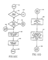
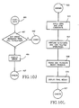
- the flow chart of Figures 10A to 10L illustrates the operation of the master controller 130 in the scale of Figures 5 and 6.
- the number of load cells in the system is extracted from memory at block 403 and the information checked at block 405. If the number of load cells has not been entered and the cells identified set up mode will be selected at block 406 and operation will jump through point 407 to decision block 410 ( Figure 10B) to check for keyboard activity. If there is keyboard activity and the system is in set up mode as determined at block 412 operation jumps through point 413 to decision block 415 ( Figure 10C) to determine if the number of load cells and their addresses are known.
- operation proceeds to decision point 417 to determine if the keyboard indicates single/total key activity. If so, operation jumps through point 418 to blocks 420 and 421 ( Figure 10D) where an appropriate display is ordered and a single cell flag set or cleared according to whether one or more load cells are in the system. Operation then jumps back through point 423 to blocks 425 and 426 ( Figure 10C) where the number of load cells is entered and addresses assigned to them.
- the load cell addresses are assigned by connecting only the first load cell to the bus, addressing it as number 240 which is assigned to all load cells at manufacture and then instructing it to change that address to the newly assigned address.
- the second load cell in the system is then connected to the bus and the procedure repeated. This continues until all load cells have been connected to the bus and assigned addresses.
- operation proceeds through point 430 to blocks 432 and 433 ( Figure 10E) where a reset command is sent to all load cells followed by an order to supply data when polled. If any cell does not respond positively as determined at block 435 the address of the highest ranking non-responsive cell is displayed at block 436 to enable operator intervention, if necessary. Operation then jumps through point 423 to blocks 425 and 426 ( Figure 10C) where load cell addresses are again assigned and then returns through point 430 to blocks 432, 433 and 435. Operation proceeds around this loop until all load cells in the system have responded positively as determined at decision block 435.
- operation proceeds through point 440 to decision block 442 ( Figure 10F) to determine if the system has exited set up mode. If not operation jumps through point 445 to block 446 ( Figure 10G) to begin checking for the activation of one or more of a series of keys which command various set up functions. If a key command is detected at decision block 446 to reassign a load cell address, operation jumps through point 448 to the procedure illustrated in Figures 12A and 12B which will be described below. Reassignment of a load cell address may become necessary when, for example, a single load cell in the system of Figures 5 and 6 has been determined to be defective and must be replaced. In that case, a new load cell must be assigned the same address as that of the load cell replaced.
- operation proceeds through point 430 to blocks 432 and 433 ( Figure 10E) where the load cells are reset and reordered to supply data. If all cells do not respond positively as determined at block 435, operation proceeds through block 436 and point 423 to blocks 425 and 426 ( Figure 10C) to again assign load cell addresses and then returns through point 430 until, as determined at block 435 ( Figure 10E), all cells respond positively. Operation then proceeds through point 440 and decision block 442 ( Figure 10F) and through point 470 and block 472 ( Figure 10H) to again read all cells at block 475.
- the single cell flag is not set operation is begun at block 500 to adjust the weight readings from the load cells for load position and to sum the readings to obtain the total weight on the scale.
- the total weight register is cleared and at block 501 a register is set to N, the number of load cells in the system.
- the load position correction constant X for the highest numbered load cell in the system is fetched from memory at block 503 and loaded into register M. If the fetching of the load position constant X for load cell N was not successful as determined at block 505, the numeral 1 is loaded into register M at block 506 and operation continues.
- Operation proceeds in the same manner as described above until the weight readings from all of the load cells have been multiplied by the respective load position correction constants and summed in the total weight register. At that point, block 514 will determine that the readings from all load cells have been summed. The zero and span calibration constants will then be fetched from memory at block 517. If the memory fetch was not successful as determined at block 519 an error display will be made at block 520 and operation will return through point 407 to block 410 ( Figure 10B). If the memory fetch was successful operation proceeds through point 522 to block 525 ( Figure 10B) where the zero and span constants are applied to the weight reading. Then, at block 527, other operations are performed relating to auto-zero and tare. At block 528 the weight reading is rounded and truncated for display and at block 530 the final weight is displayed. Operation then returns through point 407 to block 410 ( Figure 10B) to check for keyboard activity and poll the load cells for weight readings.
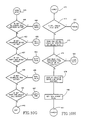
- Figure 11 illustrates the procedure for determining the values of the load position correction constants X J .
- the procedure is initiated by detection of a key command at block 457 ( Figure 10G) during set up of the scale.
- the procedure is entered through point 463 and at block 550 the no load output of each load cell is read and stored.
- a weight position counter is cleared and then incremented.
- a test weight of unknown value is then placed over the first load cell at block 554 and the output of all load cells read at block 555.
- the readings are normalized by subtracting the no load readings and the results are stored.
- a check is made to see whether the weight position count I is equal to N, the number of load cells in the system.
- operation returns to block 552 where the weight position counter is incremented and block 554 where the test weight is placed over the next load cell. Operation continues in this manner until normalized weight readings have been obtained from each of the N load cells at each of N positions of the test weight.
- the N values of B c in Equation 2 are all set equal to the average of the N sums of the readings from the N load cells. This establishes the value of B c for each equation.
- the N equations in N unknowns are solved by the method of Gaussian Elimination identified above to obtain the values of the constants X j .
- the values of the constants are then stored at block 566 and a determination made at block 568 as to whether the memory load was successful. If so, operation returns through point 440 to block 442 ( Figure 10F). If the data load was not successful an error display is ordered at block 570 and operation returns through point 440 to block 442.
- An important aspect of the present invention is the ability to replace one or more defective load cells in a multiple load cell scale and to retain the ability to correct for load position of the newly constituted scale with a minimum of difficulty. Since each load cell in the scale can be monitored and diagnosed individually a defective load cell can be easily found. When that happens, a new load cell is inserted into the system to replace the defective one, an address is assigned to the new load cell and a new load position correction constant is determined for the new load cell.
- Figures 12A and 12B illustrate the procedure for assigning the address to the new load cell.
- the procedure is entered through point 448 when a key command to reassign a load cell address has been detected at block 446 ( Figure 10G).
- Figure 10G Initially, all of the other load cells in the scale system must be disconnected from the bus so that only the new load cell is connected thereto.
- the new load cell address which in this case would be the same as that of the removed defective load cell, is entered through the keyboard at block 575 in response to a prompting message from the display.
- an address of 240 is loaded into an address register and operation proceeds through point 579 to block 580.
- a load cell address change command and the new address are transmitted to the load cell address, in this case 240, in the address register.
- a determination is made as to whether or not a positive response was obtained from the addressed load cell. If so, the new address has been satisfactorily assigned and operation returns through point 445 to scanning the keyboard at block 446 ( Figure 10G). This would normally be the result when the replacement load cell is a new load cell since address 240 is loaded into all load cells at manufacture.
- the replacement load cell would not be a new load cell and could have a stored address other than 240. In that case, operation would proceed from decision block 581 to block 583 where the contents of the address register are decremented and then, at block 585, compared to zero. If the contents of the address register are not equal to zero operation returns through point 579 to transmit the address change command and new address to the decremented load cell address and then check at block 581 for a positive response. Operation proceeds in this manner until a positive response is obtained from the replacement load cell or until the contents of the address register have been determined to be equal to zero at block 585. In that case the display is caused at block 587 to indicate that no functioning load cell is attached to the system and operation returns through point 440 to block 442 ( Figure 10F).
- the two unknowns are B6 or B3, the unknown weight, and X6.
- the multiple load cell scale described above is believed to substantially eliminate the problems described above associated with connecting together the analog electrical portions of multiple load cells.
- the techniques described provide compensation for load position and other errors in multiple load cell scales in which the analog portions of the load cells remain isolated.
Abstract
Description
- This invention relates to weighing apparatus and more particularly to weighing apparatus utilizing multiple load cells.
- Many weighing applications require the use of multiple load cells in a single scale or in a number of associated scales. For example, a heavy capacity scale for weighing trucks or railroad cars requires multiple load cells. Each load cell provides an analog signal proportional to the portion of the load borne by that load cell. Strain gages connected in a wheatstone bridge configuration often provide the analog signal. In heavy capacity applications the load is distributed over usually at least four load cells and some applications may require sixteen or more load cells. The sum of the load cell output signals must be obtained to provide a signal representative of the total load. The usual technique for summing the signals from the analog cells has been to connect the outputs in parallel to provide a single analog output signal representative of the total weight applied to the scale.
- The weighing accuracy of multiple load cell scales depends not only on the accuracy of the individual cells but also on the mechanical and electrical interaction among them. Since the load cells usually have different sensitivities to applied loads the total scale output is usually dependent upon the position of the weight on the scale. The outputs of the individual cells must, therefore, be compensated or adjusted so that the total scale output remains substantially the same for a given load no matter where on the scale it is positioned. Such load position compensation has usually been accom plished by connecting sensitivity reducing resistors in the wheatstone bridge circuit of the individual load cells, usually across the output of the bridge circuit. U.S. Patents No. 4,261,195 to Lockery, 4,574,899 to Griffen and 4,556,115 to Lockery address the problem of load position compensation in multi-load cell scales.
- Despite the solutions to the load position problem proposed in the above-identified patents, there remain problems associated with the connection of multiple analog load cells in parallel. The load cells when electrically connected together are interactive, so that a load cell will perform differently when tested alone than when tested with other load cells in a scale. The interactivity of the load cells connected together substantially complicates the problem of load position compensation by connection of resistors to individual load cells. A large number of iterations or repetitions may be required to arrive at the proper value of compensating resistor because a value initially determined to be appropriate for a particular load cell must be adjusted when compensating resistors are connected to other load cells. That adjustment can then require adjustment of the other compensating resistors, and so on.
- When the analog circuits of load cells are connected together they are essentially impossible to monitor individually. Thus, "trouble shooting" or repair of a scale can require disassembly of the electrical circuits in order to test the load cells individually and find the defective one. Further, when a load cell is replaced for any reason the scale often requires recompensation for load position. A known test weight is required to accomplish this recompensation. For large scales in particular this is a time consuming procedure and the known weight often inconvenient to obtain.
- Recently there has appeared the so-called "digital load cell" in which an analog-to-digital converter and microprocessor are dedicated to a single load cell. The electronic circuits are mounted on a printed circuit board connected directly to the counterforce of the load cell. Temperature, creep and linearity errors of the individual load cell have been compensated by digital techniques.
- According to the present invention multiple load cells associated so as to form one or more scales are connected to one or more analog-to-digital (A/D) converters to obtain a digital representation of the load on each load cell. The digital weight representations are provided to a common master controller. The master controller applies predetermined corrections to the data to produce weight readings corrected for load position. The corrections to be applied are determined by placing a load at different position on the scale, determining the responses of the load cells to the load and positions and utilizing the responses to determine the corrections.
- Preferably, each load cell is a digital load cell which includes a dedicated A/D converter and microcomputer and is connected in a local area network with the other load cells and the master controller. Each associated load cell under control of its own microcomputer and the master controller obtains digital weight readings of the load on the individual load cell and stores the data in memory associated with its own microcomputer. The master controller polls the associated load cells, and receives weight data from them.
- The connection of the load cell to provide digital weight data eliminates the problems encountered when connecting together the analog electrical portions of load cells. Because the load cells are not interactive, load position compensation can be achieved in a single, rather than iterative procedure. Also, compensation can be achieved without the need for a test weight of known value.
- Data can be obtained from individual load cells, so that each can be diagnosed and replaced if necessary without the need for disconnecting and reconnecting the entire scale or multi-load cell assembly. The diagnosis can be handled from a remote location by connection of a computer to the master controller through telephone lines and modems. Further, when one or more (up to all but one) load cells are replaced the scale can be recompensated for load position by compensating only the replacement load cells and without the need for a test weight of known value.
- One embodiment of the present invention will now be described in more detail, by way of example only, and with reference to the accompanying drawings, in which:
- Figure 1 is a block diagram of a system of multiple digital load cells embodying the present invention;
- Figure 2 is a front elevational view of a digital load cell suitable for employment in the present invention;
- Figure 3 is a top plan view of the digital load cell of Figure 2:
- Figure 4 is a block diagram of the electronic circuit of the digital load cell of Figure 2 and 3;
- Figure 5 is a plan view of a vehicle scale embodying the present invention;
- Figure 6 is a diagram illustrating the connection of the major components of the vehicle scale of Figure 5;
- Figure 7 is a block diagram of a preferred form of master controller used in the scale of Figures 5 and 6;
- Figures 8A to 8M are a flow chart illustrating the operation of each digital load cell in the present invention;
- Figures 9A and 9B are a flow chart illustrating a linearity compensation procedure employed in the digital load cell;
- Figures 10A to 10L are a flow chart illustrating the operation of the master controller of Figure 7;
- Figure 11 is a flow chart illustrating a procedure for determining the values of load position correction constants for the digital load cells in the flow chart of Figures 10A to 10L;
- Figures 12A and 12B are a flow chart illustrating the procedure for assigning an address to a replacement load cell in a multi-load cell system; and
- Figure 13 is a flow chart illustrating the procedure for determining a load position correction constant for a replacement load cell in the flow chart of Figures 10A to 10L.
- Referring now to Figure 1, a system of multiple load cells embodying the present invention includes a number of groups of
digital load cells 20, four groups being shown and identified by thenumerals 11 to 14. Theload cells 20 within eachgroup 11 to 14 are connected together throughjunction boxes multi-wire bus 30. The bus also connects the junction boxes together and to amaster controller 34. Eachgroup 11 to 14 is shown as comprising threeload cells 20 but may include from one to a large number of load cells depending upon the particular application. Thejunction boxes 22 to 25 serve as wire termination points and one may be assigned to any number of load cells that is convenient in a particular application. The junction boxes could also contain, if desired, a common A/D converter and analog switch to permit sharing rather than each load cell having a dedicated A/D converter. Fourgroups 11 to 14 of load cells are shown but, as indicated by the dashed portion ofbus 30, a greater or lesser number of groups may be employed in a given application. - The connection of the
digital load cells 20 to each other and to mastercontroller 34 throughbus 30 provides the basis for a LAN, or local area network, in which communication can occur between theindividual load cells 20 andmaster controller 34. Alternatively, eachdigital load cell 20 or the junction boxes 22-25 could be connected individually to mastercontroller 34. The LAN, however, is preferred. - In the LAN,
master controller 34 acts as the master and theindividual load cells 20 as slaves incapable of initiating communication with the master controller. Preferably, the LAN utilizes the Intel BITBUS communication system.Master controller 34 polls the load cells 20 (slaves) or selected load cells as required. The load cells respond by transmitting data or requesting information from the master controller. - In the arrangement of Figure 1, each
group 11 to 14 of one or more digital load cells may constitute an individual scale so that the combined output of all load cells in the group represents relevant weight data to be gathered and operated on bymaster controller 34. An example of such an application would be the assignment of each group to weigh one particular tank or storage bin of many receiving and discharging material. The status and amount of material delivered by each tank or bin could then be monitored and controlled throughmaster controller 34. In another application, all of theload cells 20 ingroups 22 to 25 could be in the same scale, for example distributed at selected points beneath the platform of a vehicle scale or other scale utilizing a platform for weighing. - In the case of a single scale,
master controller 34 polls all load cells periodically and sums the weight data to obtain the weight of the object on the platform. In the case of multiple scales, the system deals with only one scale at a time, as during a transfer of material into or out of the tank or bin or periodically to inventory the material remaining in the tank or bin.Master controller 34 need poll only the load cells of the particular scale and only when required. - As shown in Figures 2 and 3, each
digital load cell 20 includes a counterforce generally designated 50 to which is mechanically fastened a printedcircuit board 52. The electronic circuits mounted onboard 52 enable the load cells to provide weight information in digital form tomaster controller 34. Theparticular counterforce 50 illustrated is known as a "rocker pin" which is preferred and has certain advantages in multiple digital load cell applications. Essentially any other type of counterforce, however, could be employed. Electrical transducers in the form ofstrain gages 54 to 57 are mounted oncounterforce 50 in a conventional manner and are connected in an electrical bridge circuit to provide an analog signal indicating the load applied tocounterforce 50. Other types of transducers could also be employed, in conjunction with the rocker pin illustrated or with other types of counterforce as will be appreciated by those skilled in this art. Anickel resistor 59 is also mounted oncounterforce 50 for sensing temperature changes and enabling compensation for the effects of such changes.Strain gages 54 to 57 andnickel resistor 59 are connected by suitable wiring (not shown) to the circuitry mounted onboard 52. - As shown in Figure 4,
strain gages 54 to 57 are connected in theelectrical bridge circuit 60 which provides a weight signal to apreamplifier 63. The weight signal frompreamplifier 63 is coupled through ananalog filter 65 to one input of ananalog switch 68. The output ofanalog switch 68 is connected to the input of a multiple slope analog-to-digital (A/D)converter 70.Nickel resistor 59 is connected in series withbridge circuit 60 and provides a signal through apreamplifier 75 to another input ofanalog switch 68. Excitation is provided to bridgecircuit 60 by apower supply 77 which also provides a known reference voltage throughanalog switch 68 to multiple slope A/D 70. The output of A/D converter 70 is connected to amicroprocessor 80, preferably an Intel 8344.Microprocessor 80 controls the operation ofanalog switch 68 to cause analog weight signals frombridge 60 and temperature indicating signals fromnickel resistor 59 to be converted to digital form by A/D converter 70 and transmitted tomicroprocessor 80. -
Microprocessor 80 is provided withmemory 80a including ROM, EEPROM and RAM for storage of programs and of data received from A/D converter 70 and frommaster controller 34.Microprocessor 80 is also equipped with aserial interface unit 80b connected through adriver 85 and areceiver 86 tobus 30 for communication withmaster controller 34. - Each of the digital load cells illustrated in Figures 2, 3 and 4 is programmed to operate as a slave to the master controller and to respond to commands directed to it. Each load cell has a unique address stored in local memory which allows the master controller to send commands to it only. All load cells are provided during manufacture with the same address which is replaced with a unique address during set up of the scale.
- Each digital load cell is also programmed to compensate its weight readings for temperature effects on zero and span, for span trim and for linearity and creep. The compensation algorithms employed including the values of the constants are stored in the load cell memory. The values of the constants are determined during manufacture of the load cell. The constants are determined by connecting the load cell to a host computer during manufacture, subjecting the load cell to the varying weights and temperature conditions required to provide data for use in the corrective algorithms and using the data to solve for the respective constants. The constants are then transmitted by the host computer to the load cell and stored in memory.
- Referring to Figures 5 and 6, there is shown a system similar to the general application system of Figure 1 but configured as a single scale for weighing vehicles. The system includes eight
digital load cells 20 as described above supporting aplatform 125 suitable for holding a vehicle such as a truck. Theload cells 20 are connected together through ajunction box 127 and through abus 128 to amaster controller 130. The master controller may be connected to one or moreperipheral devices 132 such as a printer or host computer. Thedigital load cells 20 andmaster controller 130 are arranged and programmed to constitute a LAN withmaster controller 130 performing as the master and theload cells 20 as slaves. As in the system of Figure 1, preferably the LAN utilizes the Intel BITBUS communication system. - As shown in Figure 7,
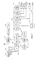
master controller 130 includes amicroprocessor 140, preferably an Intel 8344, provided withinternal RAM memory 140a and aserial interface unit 140b.Microprocessor 140 is connected tobus 128 for communication with thedigital load cells 20 throughdriver 142 andreceiver 143 connected toserial interface unit 140b.Microprocessor 140 also communicates with an address/data bus 150 to which is connected aprogram memory 152,RAM 153,real time clock 154 and a pair ofdual transmitters Transmitters connect bus 150 to various peripheral devices such as aprinter 160,host computer 161, bar code encoder 163 and a serial input/output line 164. A parallel input/output line 166 is also connected tobus 150 through alatch 167. -
Microprocessor 140 provides weight data to a seven digit vacuumfluorescent display 172 through adisplay control 174. Akeyboard 180 is connected tomicroprocessor 140 through akeyboard drive 182 for manual selection and inputting of various modes and options during calibration and set up of the system and for making slight changes in operation of the system. A non-volatileprogrammable memory 183 is also connected tomicroprocessor 140 for the storage of various calibration constants and similar information determined during calibration and set up of the system. - The master controller shown in Figure 7 is manufactured and sold by Toledo Scale Corporation, applicant of the present application, as a Model 8530 Digital Indicator.
- In operation of the system of Figure 1 or Figures 5 and 6, the master controller, acting as a LAN master, polls the load cells, LAN satellites or slaves, at a desired rate to receive weight data from each load cell. The data from each load cell may be operated on in certain respects, summed with the data from other load cells of the scale and the result further operated on to produce the final displayed weight. In the case of the multiple scale system of Figure 1, the master controller polls only the load cells of a particular scale and operates on the information received in the same manner as described above. In each system, single scale and multiscale, each scale involved would require calibration and set up prior to operation.
- Although connection and operation as a LAN is preferred, the digital output of each load cell, or group of load cells sharing an A/D converter, could be connected individually to the master controller rather than through a common bus. The essential feature is that the master controller receive and operate on digital information from each of the multiple load cells.
- The arrangement is such as to allow the multiple load cell scale to be corrected digitally for load position errors. In the scale of Figures 5 and 6, when the same weight is placed at the same spot on
platform 125 at different times the weight signals from the individualdigital load cells 20 will be the same. When, however, the weight is placed in a different position on the platform the digital signals from the load cells (and their sum) may increase, decrease or remain the same according to the new position of the weight. In accordance with the present invention, these digital signals are modified so that the sum of the modified signals representing the weight onplatform 125 remains substantially the same for different positions of the same weight on the platform. - The total weight, B, on
platform 125 can be represented as:
B = A₁+A₂+A₃+---+AN
where N is the number of load cells in the scale, and
Aj are the digital weight readings from the individual load cells.
The total weight onplatform 125 corrected for load position can be represented by:
Bc = A₁X₁+A₂X₂+A₃X₃+---+ANXN (1)
where Bc is the total weight corrected for load position,
Xj are constant load position correction factors for the individual load cells.
When the values of the load position correction factors, Xj, are known for the individual load cells they can be stored at themaster controller 130 and used during operation to correct the load cell weight readings for load position. - The values of the coefficients Xj for the individual load cells may be determined during calibration and set-up of the scale. The values of the coefficients may be determined utilizing equation (1) above and weight readings taken from each of the load cells with the same test weight placed at various positions on
platform 125. For a scale having N load cells the same weight is placed sequentially at each of N positions on platform 125 (Figures 5, 6) and weight readings taken from each load cell at each position. The resulting data can be utilized to construct N equations of the form of equation (1) above in N unknowns, one equation for each position of the weight onplatform 125. In each of the equations, Aj are the weight readings from the N load cells with the test weight at the same position and Xj are the unknown values of the constant coefficients. Bc could be set equal to the value of the test weight. According to the present invention, however, the value of the test weight used need not be known. This is an advantage since test weights of known value are often very difficult to obtain, particularly for large vehicle scales. With the value of the test weight unknown, Bc is set equal to the same number in each of the N equations of the form of equation (1). For example, Bc in each equation could be set equal to the average of the N sums of the readings from the N load cells. - Solving for the values of the N unknown coefficients in the N equations can be accomplished by any of many generally known methods for the solution of simultaneous equations. A preferred method is known as "Gaussian Elimination Without Interchange". This method is described in many textbooks including "Linear Algebra With Applications" (2nd Edition) by S.J. Leon, published by McMillan Publishing Company, 1986. To ensure accurate solutions this technique requires that each load cell have one weight position reading in which it has the highest output of any of the N load cells. In cases where the test weight can be placed over essentially only one load cell at a time this condition is easily met. In usual practice, the weight is shared by many load cells but in the great majority of these cases the positions of the known weight can be chosen to ensure that a different one of the load cells bears most of the load for each of the positions.
- In certain scales, it may not be possible to place the test weight over or sufficiently close to each individual load cell to meet the requirement. Such a problem would be encountered, for example, in a truck scale that is only slightly wider than the truck employed as the weight. In this case, the load cells could be loaded in pairs. That is, a pair of load cells is considered as one and the scale is loaded so that a different pair at each weighing position has the highest output of the load cells. In operation, the scale would be adequately load position compensated so long as substantially narrower loads are not used on the scale.
- The correction equation for such a scale having N load cells is of the form:
Bc=(A₁+A₂)X₁+(A₃+A₄)X₂+(A₅+A₆)X₃+---+(AN-1+AN)X
where Bc, Xj and Aj are as defined in equation (1) above. - When the test weight cannot be placed so that each load cell has one weight position reading in which it has the highest output of any of the N load cells then the method of "Gaussian Elimination Without Interchange" may not provide satisfactory solutions. In that case, more conventional but time and computer memory consuming methods can be employed, for example, the method of matrices or any other standard method for solving N simultaneous equations in N unknowns. It remains a requirement that the equations be independent.
- Prior to operation of the scale system of Figures 5 and 6 it must be set up and calibrated. This occurs after the load cells have been positioned beneath the weighing platform but prior to connection of the individual load cells to the master controller in the local area network. The set up mode is selected through the keyboard of the master controller and the number of load cells in the scale system is entered by the same means. Addresses are then assigned to the load cells in sequence beginning with
number 1. Only the first load cell is connected to the bus andaddress number 1 transmitted to it and stored in the load cell memory. The second load cell in the system is then connected to the bus and address number 2 assigned to it in the same way. The process continues until all of the load cells have been connected to the bus and assigned different addresses. The master controller is then able to communicate with each of the load cells in the local area network for continued calibration and set up. - Another step in the set up procedure is determination of the load position correction constants in equation (1) above. In this procedure, a test weight, which can be of unknown value, is placed over the first load cell of the scale and weight readings taken from each of the load cells and stored in the master controller memory. The same weight is then positioned over the second load cell and weight readings taken and stored. This process is continued until weight readings have been taken for all of the N load cells with the same weight at each of the N positions. The data is used to construct and solve N equations in N unknowns by the technique described above to obtain the values of the load position correction constants. The constants are stored in memory at the master controller along with equation (1) for use in correcting the weight readings for load position during operation. In some cases, one or more of the load cells outputs might not require correction for load position. In that case, the correction constant would simply be equal to 1 and the corrected and uncorrected readings from that load cell or cells would be equal.
- During set up the system is also calibrated for zero and span and calibration values obtained in the process are stored in memory at the master controller for use in weighing operations.
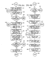
- The flow chart of Figures 8A to 8M illustrates the operation of the digital load cell, whether connected in the system of Figures 5 and 6 or connected to a host computer for calibration and calculation of correction constants during manufacture. After START at
block 250 operation is begun in the "silent" mode atblock 251. This is essentially a local mode in that the master controller or host computer has not yet initiated communication with the load cell. Atblocks block 255. After the stored address has been determined to be valid or a new one assigned, operation proceeds directly or throughpoint 254 to block 257 where a check is made for ROM errors and a flag is set if any such errors are found. Then, at block 259 a temperature reading is obtained fromnickel resistor 59 in Figure 4 and stored for compensation use. At block 260 a digital weight reading is taken and a negative out-of-range flag cleared. The weight reading is checked atblock 262 to determine whether or not it is out of range. If not, operation proceeds throughpoint 264 to block 268 (Figure 8B) where a determination is made as to whether the data should be compensated or presented in its raw form. If, atblock 262, the weight reading is determined to be out-of-range a flag is set atblock 269 and operation proceeds throughpoint 270 to block 272 (Figure 8B). Likewise, if the weight reading is not to be compensated as determined atblock 268 operation jumps throughpoints 270 to block 272. - If the weight reading is to be compensated a subroutine is performed at
block 275 to temperature compensate the zero and span coefficients. At block 276 a subroutine "LINCOR" is utilized to correct the weight reading for nonlinearity as will be described below. Subroutines are performed atblocks - At
blocks point 284 to block 286 (Figure 8C) where it is determined whether or not the load cell is in the silent mode. If not, the weight and temperature readings are loaded atblock 288 into a serial buffer for transmission and operation proceeds to block 290. If the load cell is insilent mode block 288 is bypassed throughpoint 291 to block 290 where a check is made for any messages received from a host computer or master controller. If there are no messages and the cell is in silent mode as determined atblock 292, operation returns throughpoint 293 to the main loop atblock 252 and the operation described above is repeated. If the load cell is not in the silent mode operation proceeds fromblock 292 to block 295 and cycles throughpoint 296 until the serial buffer is empty, indicating that the weight and temperature readings have been transmitted to the master controller or host computer. At that time operation returns throughpoint 293 to the main loop at block 252 (Figure 8A). - When a message has been received as determined at
block 290 operation proceeds throughpoint 298 to block 300 (Figure 8D) where the validity of the message is determined. If the message is not valid a response to that effect is sent atblock 301 and operation returns throughpoint 296 to block 295. If the message is valid as determined atblock 300 operation proceeds throughpoint 303 to block 305 (Figure 8E) to determine the content of the message. A message command to reset causes operation to return toSTART point 250. If the message is a command to activate data output as determined atblock 307, silent mode is disabled atblock 308 in favor of an active data mode. Operation then proceeds throughpoint 310 to block 311 (Figure 8M) to respond to the master controller or host computer that the order is implemented. The cycle then proceeds throughpoint 296 to block 295 (Figure 8C) to transmit the data and return to the beginning of operation atblock 252. - If the message was determined at block 307 (Figure 8E) to be other than a command to activate data output, operation proceeds through
point 315 to block 316 (Figure 8F) to determine if the message is a command for data in raw or compensated form. If so, the ordered data mode is set atblock 317, a response is made throughpoint 310 and block 311 that the command has been implemented and operation returns throughpoint 296 to block 295. - If the message was not a data form command as determined at
block 316, operation proceeds throughpoint 319 to a series of inquiries to determine whether or not the message is one containing compensation data, such as algorithm compensation constants, to be stored in memory. At block 322 (Figure 8G), a determination is made as to whether or not the message includes temperature compensation data. If not, operation proceeds throughpoint 323 to, in sequence, block 326 (Figure 8H) to determine if the data is creep compensation data,point 327 and block 329 (Figure 8J) to determine if the data is linearity compensation data, andpoint 330 and block 331 (Figure 8K) to determine if the data is span trim calibration data. If the message is determined to contain one of the types of compensation data, operation proceeds throughpoint 333 to block 335 (Figure 8G) where the data is stored in memory. A check is then made atblock 336 to determine if the data load was successful. If so, operation proceeds throughpoint 310 to block 311 to respond that the message command has been implemented and then throughpoint 296 to block 295. If the data load was not successful, a response to that effect is sent atblock 338 and operation proceeds throughpoint 296 to block 295. - It should be noted that compensation constants for correcting for temperature, creep, linearity, and span trim calibration are transmitted to the digital load cell only during set up as part of the manufacturing process. Accordingly, results of the tests described above for the presence of such data in a received message would be negative when the load cell is operating as a part of the scale system of Figures 5 and 6.
- Referring again to Figures 8A to 8M, when the received message has undergone the last test for containing of data constants at block 331 (Figure 8K), operation proceeds through
point 340 to block 341 (Figure 8L) for a determination as to whether the message includes an address assignment for the load cell. If not, operation proceeds throughpoint 296 to block 295. If the message is an address assignment the address is stored in memory atblock 343 and a check made atblock 344 to determine if loading of the address was accomplished satisfactorily. When the address load was not satisfactory a response to that effect is sent atblock 345 and operation proceeds throughpoint 296 to block 295. If the address was loaded successfully as determined atblock 344, operation proceeds throughpoint 310 to block 311 (Figure 8M) for transmission of a response that the command has been implemented. Operation then proceeds throughpoint 296 to block 295. - Figures 9A and 9B illustrate the steps in subroutine LINCOR performed at block 276 (Figure 8B) for providing a linearity correction to the weight reading. The subroutine is entered at point 350 (Figure 9A) and proceeds to block 351 where the linearity compensation constants D and E are loaded. Operation then proceeds to block 353 where a check is made to determine if the constants were loaded correctly. If not, operation proceeds through
point 354 to block 355 (Figure 9B) where an error flag is set and operation returns throughpoint 357 to the main program atblock 277. If the linearity compensation constants were loaded satisfactorily as determined atblock 353, operation proceeds to block 358 where a linearity-corrected weight reading is calculated and stored. Operation then returns throughpoint 357 to block 277 in the main program. - It will be apparent from the foregoing description that the operation of each digital load cell in the system of Figures 5 and 6, once the load cell has been assigned an address and transferred from a silent to an active data mode, consists primarily of taking weight and temperature readings, compensating the weight reading for various factors mentioned above and providing it to the master controller.
- The flow chart of Figures 10A to 10L illustrates the operation of the
master controller 130 in the scale of Figures 5 and 6. After power up atblock 400 and some initializing steps atblock 401 the number of load cells in the system is extracted from memory atblock 403 and the information checked atblock 405. If the number of load cells has not been entered and the cells identified set up mode will be selected atblock 406 and operation will jump throughpoint 407 to decision block 410 (Figure 10B) to check for keyboard activity. If there is keyboard activity and the system is in set up mode as determined atblock 412 operation jumps throughpoint 413 to decision block 415 (Figure 10C) to determine if the number of load cells and their addresses are known. Since they are not, operation proceeds todecision point 417 to determine if the keyboard indicates single/total key activity. If so, operation jumps throughpoint 418 toblocks 420 and 421 (Figure 10D) where an appropriate display is ordered and a single cell flag set or cleared according to whether one or more load cells are in the system. Operation then jumps back throughpoint 423 toblocks 425 and 426 (Figure 10C) where the number of load cells is entered and addresses assigned to them. The load cell addresses are assigned by connecting only the first load cell to the bus, addressing it asnumber 240 which is assigned to all load cells at manufacture and then instructing it to change that address to the newly assigned address. The second load cell in the system is then connected to the bus and the procedure repeated. This continues until all load cells have been connected to the bus and assigned addresses. - From
block 426 operation proceeds throughpoint 430 toblocks 432 and 433 (Figure 10E) where a reset command is sent to all load cells followed by an order to supply data when polled. If any cell does not respond positively as determined atblock 435 the address of the highest ranking non-responsive cell is displayed atblock 436 to enable operator intervention, if necessary. Operation then jumps throughpoint 423 toblocks 425 and 426 (Figure 10C) where load cell addresses are again assigned and then returns throughpoint 430 toblocks decision block 435. - From
decision point 435, operation proceeds throughpoint 440 to decision block 442 (Figure 10F) to determine if the system has exited set up mode. If not operation jumps throughpoint 445 to block 446 (Figure 10G) to begin checking for the activation of one or more of a series of keys which command various set up functions. If a key command is detected atdecision block 446 to reassign a load cell address, operation jumps throughpoint 448 to the procedure illustrated in Figures 12A and 12B which will be described below. Reassignment of a load cell address may become necessary when, for example, a single load cell in the system of Figures 5 and 6 has been determined to be defective and must be replaced. In that case, a new load cell must be assigned the same address as that of the load cell replaced. - At the end of the load cell address reassignment procedure operation returns through point 440 (Figure 10F) to decision block 442 to determine whether or not the set up mode has yet been exited. If not, operation proceeds through
point 445 to resume scanning for key commands. If, at decision block 453 (Figure 10G), a key command has been received to calibrate the scale operation jumps throughpoint 455 to that procedure. When the calibration operation is completed operation returns throughpoint 440 to decision block 442 (Figure 10F) and throughpoint 445 to resume scanning for key commands. Operation continues in this manner through decision blocks 457, 459 and 461. A shift adjust key command atblock 457 initiates through point 463 a procedure illustrated in Figure 11 described below. A key command detected atblock 459 initiates a calibration trim procedure throughpoint 465. A key command atblock 461 causes operation to jump throughpoint 467 to the procedure illustrated in Figure 13 and described below. - When all key commands have been satisfied operation proceeds through
point 440 to block 442 (Figure 10F). When set up mode has been exited operation proceeds throughpoint 470 to decision block 472 (Figure 10H). If no load cell error flag has been set, readings are taken from all of the load cells atblock 475 and a check made atblock 476 to determine if data was received from all cells. If not, the addresses of the load cells in error are displayed atblock 478 and a cell error flag set atblock 480. Operation then jumps throughpoint 407 to decision block 410 (Figure 10B) and if there is no keyboard activity returns throughpoint 470 todecision block 472. Since the cell error flag has been set, operation proceeds throughpoint 430 toblocks 432 and 433 (Figure 10E) where the load cells are reset and reordered to supply data. If all cells do not respond positively as determined atblock 435, operation proceeds throughblock 436 andpoint 423 toblocks 425 and 426 (Figure 10C) to again assign load cell addresses and then returns throughpoint 430 until, as determined at block 435 (Figure 10E), all cells respond positively. Operation then proceeds throughpoint 440 and decision block 442 (Figure 10F) and throughpoint 470 and block 472 (Figure 10H) to again read all cells atblock 475. - When, as determined at
block 476, data is obtained from all load cells operation proceeds throughpoint 485 to decision block 487 (Figure 10J) to check for any error messages received with the load cell data. If any such error messages are received the fact is displayed atblock 489 and operation proceeds throughpoint 407 to block 410 (Figure 10B). If there is no keyboard activity operation returns throughpoint 470 to again read data at block 475 (Figure 10H) from all the load cells. When a determination is made at block 487 (Figure 10J) that no error messages have been received with the data, operation proceeds throughpoint 492 to decision block 494 (Figure 10K). If, as determined atblock 494, the single cell flag is set operation jumps throughpoint 496 to block 497 (Figure 10B) where the single load cell data is displayed. Operation then returns to point 470 (Figure 10H) throughblock 410 alone or throughblocks - If, as determined at block 494 (Figure 10K), the single cell flag is not set operation is begun at
block 500 to adjust the weight readings from the load cells for load position and to sum the readings to obtain the total weight on the scale. Atblock 500 the total weight register is cleared and at block 501 a register is set to N, the number of load cells in the system. The load position correction constant X for the highest numbered load cell in the system is fetched from memory atblock 503 and loaded into register M. If the fetching of the load position constant X for load cell N was not successful as determined atblock 505, thenumeral 1 is loaded into register M atblock 506 and operation continues. If the load position constant was successfully fetched from memory as determined atblock 505 operation jumps throughpoint 508 to block 510 where the weight reading from load cell N is multiplied by load position constant XN stored in register M and the result added to the total weight register. Then, atblock 512, N is decremented and tested atblock 514 to determine if it is equal to zero. If not, operation returns throughpoint 515 to block 503 where the shift adjust constant X for the next highest numbered load cell in the system is fetched from memory and loaded into register M. - Operation proceeds in the same manner as described above until the weight readings from all of the load cells have been multiplied by the respective load position correction constants and summed in the total weight register. At that point, block 514 will determine that the readings from all load cells have been summed. The zero and span calibration constants will then be fetched from memory at
block 517. If the memory fetch was not successful as determined atblock 519 an error display will be made atblock 520 and operation will return throughpoint 407 to block 410 (Figure 10B). If the memory fetch was successful operation proceeds throughpoint 522 to block 525 (Figure 10B) where the zero and span constants are applied to the weight reading. Then, atblock 527, other operations are performed relating to auto-zero and tare. Atblock 528 the weight reading is rounded and truncated for display and atblock 530 the final weight is displayed. Operation then returns throughpoint 407 to block 410 (Figure 10B) to check for keyboard activity and poll the load cells for weight readings. - Returning to Figure 10A and
decision block 405, the above description assumed that addresses had not yet been assigned to the load cells in the system. If, however, addresses had previously been assigned as determined atblock 405 operation would proceed throughpoint 535 to block 540 where preparations would be made for polling the load cells. Operation would then proceed as described above with reset commands being sent to all load cells atblock 432. - Figure 11 illustrates the procedure for determining the values of the load position correction constants XJ. The procedure is initiated by detection of a key command at block 457 (Figure 10G) during set up of the scale. The procedure is entered through
point 463 and atblock 550 the no load output of each load cell is read and stored. Atblocks 551 and 552 a weight position counter is cleared and then incremented. A test weight of unknown value is then placed over the first load cell atblock 554 and the output of all load cells read atblock 555. Then, atblock 557 the readings are normalized by subtracting the no load readings and the results are stored. Atblock 560, a check is made to see whether the weight position count I is equal to N, the number of load cells in the system. If not, operation returns to block 552 where the weight position counter is incremented and block 554 where the test weight is placed over the next load cell. Operation continues in this manner until normalized weight readings have been obtained from each of the N load cells at each of N positions of the test weight. - Then, at
block 563 the N values of Bc in Equation 2 are all set equal to the average of the N sums of the readings from the N load cells. This establishes the value of Bc for each equation. Then, atblock 565, the N equations in N unknowns are solved by the method of Gaussian Elimination identified above to obtain the values of the constants Xj. The values of the constants are then stored atblock 566 and a determination made atblock 568 as to whether the memory load was successful. If so, operation returns throughpoint 440 to block 442 (Figure 10F). If the data load was not successful an error display is ordered atblock 570 and operation returns throughpoint 440 to block 442. - An important aspect of the present invention is the ability to replace one or more defective load cells in a multiple load cell scale and to retain the ability to correct for load position of the newly constituted scale with a minimum of difficulty. Since each load cell in the scale can be monitored and diagnosed individually a defective load cell can be easily found. When that happens, a new load cell is inserted into the system to replace the defective one, an address is assigned to the new load cell and a new load position correction constant is determined for the new load cell.
- Figures 12A and 12B illustrate the procedure for assigning the address to the new load cell. The procedure is entered through
point 448 when a key command to reassign a load cell address has been detected at block 446 (Figure 10G). Initially, all of the other load cells in the scale system must be disconnected from the bus so that only the new load cell is connected thereto. Referring to Figure 12A, the new load cell address, which in this case would be the same as that of the removed defective load cell, is entered through the keyboard atblock 575 in response to a prompting message from the display. - At
block 578 an address of 240 is loaded into an address register and operation proceeds throughpoint 579 to block 580. There, a load cell address change command and the new address are transmitted to the load cell address, in thiscase 240, in the address register. Then, at block 581 a determination is made as to whether or not a positive response was obtained from the addressed load cell. If so, the new address has been satisfactorily assigned and operation returns throughpoint 445 to scanning the keyboard at block 446 (Figure 10G). This would normally be the result when the replacement load cell is a new load cell sinceaddress 240 is loaded into all load cells at manufacture. - In some cases, however, the replacement load cell would not be a new load cell and could have a stored address other than 240. In that case, operation would proceed from
decision block 581 to block 583 where the contents of the address register are decremented and then, atblock 585, compared to zero. If the contents of the address register are not equal to zero operation returns throughpoint 579 to transmit the address change command and new address to the decremented load cell address and then check atblock 581 for a positive response. Operation proceeds in this manner until a positive response is obtained from the replacement load cell or until the contents of the address register have been determined to be equal to zero atblock 585. In that case the display is caused atblock 587 to indicate that no functioning load cell is attached to the system and operation returns throughpoint 440 to block 442 (Figure 10F). - With the replacement load cell installed the scale must now be recompensated for load position. Assuming that load position correction constants have previously been determined for each load cell in the scale, that only one load cell is replaced and that the change of load cells does not affect the correction constants of the unchanged load cells, a correction constant for the new load cell may be obtained using an unknown weight and only two weight readings. The load position corrected output of a scale having a load positioned at any weight position i on a scale of N load cells is given by:
Bi = (Ai,1)X₁ + (Ai,2)X₂ + ... + (Ai,N)XN (2)
where, Ai,j is the output reading of the jth load cell with the weight at position i, and
Xj is the correction constant for the jth load cell.
Under the assumptions given above values of Xj for all load cells except the one added are known. If, for example, the sixth load cell were to be replaced then a new X₆ would have to be calculated. In equation (2) above there are two unknowns, X₆ and the test weight B. Since there are two unknowns only two equations are required to determine the values of the unknowns. To obtain the required data, a test weight of unknown value is first placed over the new load cell, No. 6, and readings taken for each load cell in the scale. The unknown weight is then positioned at a different position (preferably, so that the load on the replacement load cell is minimized) and weight readings taken from each of the load cells. Equation (2) with the data from the first set of readings with the weight on new load cell No. 6 is:
B₆ = (A6,1)X₁ + (A6,2)X₂ + ... + (A6,N)XN. The equation for the second set of data where the same unknown weight is positioned over, for example, load cell No. 3, is:
B₃ = (A3,1)X₁ + (A3,2)X₂ + ... + (A3,N)XN. - If the same weight is used for both measurements then:
B₆ = B₃ - The above equations can be simplified to:
B₆ = (A6,6)X₆ + Z₆
B₃ = (A3,6)X₆ + Z₃
where Z₆ is the sum of the products of the load cell outputs and position correction constants for all but the sixth load cell, and Z₃ is the sum of the products of the load cell outputs and the load position correction constants for all but the third load cell. - The two unknowns are B₆ or B₃, the unknown weight, and X₆.
- Since B₆ = B₃, the two equations can be combined into one equation with one unknown, X₆,
(A6,6)X₆ + Z₆ = (A3,6)X₆ + Z₃
rearranging,
- It should be noted that substantially similar procedures could be employed to replace two or more load cells at the same time and obtain the values of their load position correction constants. In the case of replacing two cells at the same time three weight readings would be needed and the solution to three simultaneous equations. In the case of three, four or up to all but one of the load cells being replaced, extensions of the technique described above could be employed.
- Referring now to Figure 13, the procedure for computing the load position correction constant for a new load cell added to the scale is entered through
point 467 when a key command is detected at block 461 (Figure 10G). After entry atpoint 467, the unknown weight is placed over the new load cell atblock 600 and the output of all load cells is read atblock 601. Then, atblock 603 the same unknown weight is moved to a new position and the output of all load cells again read atblock 605. The load position correction constant, X, for the new load cell is calculated atblock 607 from equation (3) in the manner described above and the constant is loaded into memory atblock 608. If the memory load was successful as determined atblock 609 operation returns throughpoint 440 to block 442 (Figure 10F). If the memory load was not successful operation jumps throughpoint 610 to block 570 (Figure 11) to cause the display the indicate a memory storage error and then proceeds throughpoint 440 to block 442 (Figure 10F). - The multiple load cell scale described above is believed to substantially eliminate the problems described above associated with connecting together the analog electrical portions of multiple load cells. The techniques described provide compensation for load position and other errors in multiple load cell scales in which the analog portions of the load cells remain isolated.
Claims (16)
Applications Claiming Priority (2)
| Application Number | Priority Date | Filing Date | Title |
|---|---|---|---|
| US07/126,271 US4804052A (en) | 1987-11-30 | 1987-11-30 | Compensated multiple load cell scale |
| US126271 | 1987-11-30 |
Publications (3)
| Publication Number | Publication Date |
|---|---|
| EP0319202A2 true EP0319202A2 (en) | 1989-06-07 |
| EP0319202A3 EP0319202A3 (en) | 1990-11-14 |
| EP0319202B1 EP0319202B1 (en) | 1993-03-31 |
Family
ID=22423927
Family Applications (1)
| Application Number | Title | Priority Date | Filing Date |
|---|---|---|---|
| EP88311168A Expired - Lifetime EP0319202B1 (en) | 1987-11-30 | 1988-11-25 | Compensated multiple load cell scale |
Country Status (9)
| Country | Link |
|---|---|
| US (1) | US4804052A (en) |
| EP (1) | EP0319202B1 (en) |
| JP (1) | JPH0781904B2 (en) |
| CN (1) | CN1016728B (en) |
| AU (1) | AU599883B2 (en) |
| BR (1) | BR8806295A (en) |
| CA (1) | CA1303073C (en) |
| DE (1) | DE3879894T2 (en) |
| MX (1) | MX164997B (en) |
Cited By (12)
| Publication number | Priority date | Publication date | Assignee | Title |
|---|---|---|---|---|
| WO1993018374A1 (en) * | 1992-03-13 | 1993-09-16 | Fairbanks, Inc. | Microwave electronic load measuring system |
| EP0825425A2 (en) * | 1996-08-23 | 1998-02-25 | Yamato Scale Co., Ltd. | Weighing system |
| EP0825424A2 (en) * | 1996-08-23 | 1998-02-25 | Yamato Scale Co., Ltd. | Weighing and packing system |
| US6566613B1 (en) | 2000-11-03 | 2003-05-20 | Enzo Gesuita | Control system for multihead weigher |
| WO2003098169A1 (en) * | 2002-05-15 | 2003-11-27 | Sartorius Ag | Force-measuring system comprising several force-measuring cells and a circuit calculating a total signal |
| WO2003106939A1 (en) * | 2002-06-13 | 2003-12-24 | Bizerba Gmbh & Co. Kg | Method for replacing digital load cells |
| WO2004099737A1 (en) * | 2003-05-09 | 2004-11-18 | Societa' Cooperativa Bilanciai-Campogalliano A R.L. | Weighing system |
| EP1602907A1 (en) * | 2004-05-31 | 2005-12-07 | Gefran Sensori S.r.l. | Automatic sensor correction with feedback microprocessor |
| EP1895280A2 (en) | 2006-09-04 | 2008-03-05 | Wipotec Wiege- und Positioniersysteme GmbH | Weighing device, in particular weighing cell for a composite weighing machine |
| DE102007058919A1 (en) * | 2007-12-05 | 2009-06-10 | Sartorius Ag | Weighing device with a plurality of digital load cells, load cell and method |
| US10260934B2 (en) | 2016-02-10 | 2019-04-16 | Riyaz Esmail | Portable scale system |
| US10554710B2 (en) | 2005-12-10 | 2020-02-04 | Samsung Electronics Co., Ltd. | Method and device for switching media renderers during streaming playback of content |
Families Citing this family (66)
| Publication number | Priority date | Publication date | Assignee | Title |
|---|---|---|---|---|
| US4815547A (en) * | 1987-11-30 | 1989-03-28 | Toledo Scale Corporation | Load cell |
| US4967384A (en) * | 1988-03-14 | 1990-10-30 | General Electrodynamics Corporation | Highly accurate weighing system |
| US5002141A (en) * | 1989-12-08 | 1991-03-26 | Toledo Scale Corporation | Vehicle weighing in motion apparatus and method |
| US5131482A (en) * | 1989-12-28 | 1992-07-21 | General Electrodynamics | Self-contained weighing system and method |
| US5756938A (en) * | 1990-01-25 | 1998-05-26 | Ishida Scales Mfg. Co., Ltd. | Weight measuring apparatus |
| WO1991011687A1 (en) * | 1990-01-25 | 1991-08-08 | Ishida Scales Mfg. Co., Ltd. | Weight measuring apparatus |
| US5004058A (en) * | 1990-03-27 | 1991-04-02 | Cardinal Scale Manufacturing Company | Weigh scale using multiple digital load cells |
| JPH0656315B2 (en) * | 1990-07-24 | 1994-07-27 | 株式会社イシダ | Weight measuring device |
| US5392027A (en) * | 1991-11-04 | 1995-02-21 | Detek Security Systems, Inc. | Full bridge strain gage deflection sensor |
| JP3539582B2 (en) * | 1993-12-02 | 2004-07-07 | 株式会社イシダ | Multi-point cell type weighing device |
| US5623128A (en) * | 1994-03-01 | 1997-04-22 | Mettler-Toledo, Inc. | Load cell with modular calibration components |
| US6034334A (en) * | 1994-04-12 | 2000-03-07 | Ishida Co. Ltd. | Method of and means for correcting effects of floor vibrations on weight signals from a weighing machine |
| US5606516A (en) * | 1995-08-07 | 1997-02-25 | Fairbanks Scales Inc. | Digitally compensated hydraulic scale system |
| US5750937A (en) * | 1996-03-07 | 1998-05-12 | Weigh-Tronix, Inc. | Multi-load cell force sensing apparatus |
| US5724267A (en) * | 1996-07-02 | 1998-03-03 | Richards; James L. | Weight measuring apparatus using a plurality of sensors |
| US6112162A (en) * | 1997-07-11 | 2000-08-29 | Richards; James L. | Weight measuring apparatus using a plurality of sensors |
| US6260003B1 (en) * | 1998-12-11 | 2001-07-10 | Cardinal Scale Manufacturing Company | Statistical compensation of load position on a platform scale |
| DE10005445C2 (en) | 1999-02-08 | 2002-08-14 | Takata Corp | Diagnostic method for a seat load measuring device |
| US6639156B2 (en) * | 1999-12-30 | 2003-10-28 | Tom J. Luke | Method and device for monitoring inventory |
| JP2001330507A (en) * | 2000-05-23 | 2001-11-30 | Yazaki Corp | Sensor unit, and sensor unit adjusting system |
| DE10042966A1 (en) * | 2000-08-31 | 2002-03-21 | Mettler Toledo Albstadt Gmbh | Scale and method for operating a scale |
| US6915233B2 (en) * | 2001-03-29 | 2005-07-05 | Hee Chul Han | Apparatus and method for measuring a weight load exerted by a leg of a lab animal or a human being |
| US6629056B2 (en) * | 2001-03-29 | 2003-09-30 | Hee Chul Han | Apparatus and method for measuring a weight load exerted by a leg of a lab animal |
| JP2002340664A (en) * | 2001-05-14 | 2002-11-27 | Shimadzu Corp | Electronic balance |
| US6919516B2 (en) * | 2002-01-08 | 2005-07-19 | Mettler-Toledo | RF multiple load cell scale |
| US6636820B2 (en) | 2002-02-20 | 2003-10-21 | Becs Technology, Inc. | Method and apparatus for measuring weight using uncalibrated load cells |
| KR100441685B1 (en) * | 2002-09-19 | 2004-07-27 | 삼성전자주식회사 | Dual damascene process |
| US20050086133A1 (en) * | 2003-01-08 | 2005-04-21 | Scherer William H. | System and method for sensing and analyzing inventory levels and consumer buying habits |
| US6985799B2 (en) * | 2003-05-13 | 2006-01-10 | Bae Systems Controls, Inc. | Energy storage modules and management system |
| US7009118B2 (en) * | 2003-05-13 | 2006-03-07 | Dynamic Datum Llc | Vehicle load weighing system and load cells for such systems |
| US7813973B2 (en) * | 2003-10-10 | 2010-10-12 | Inventrol Llc | Inventory monitoring system |
| US7253366B2 (en) * | 2004-08-09 | 2007-08-07 | Hill-Rom Services, Inc. | Exit alarm for a hospital bed triggered by individual load cell weight readings exceeding a predetermined threshold |
| US7423225B1 (en) * | 2004-11-09 | 2008-09-09 | Intercomp Company | Weigh in motion technology |
| US7158916B1 (en) | 2004-11-16 | 2007-01-02 | Yarian John C | Method for analyzing net weights of packaged goods |
| US7305324B2 (en) * | 2004-11-24 | 2007-12-04 | Ut-Battelle, Llc | System and method for identifying, validating, weighing and characterizing moving or stationary vehicles and cargo |
| JPWO2006132235A1 (en) * | 2005-06-07 | 2009-01-08 | 株式会社島津製作所 | Load cell electronic balance |
| AU2006257880B2 (en) | 2005-06-10 | 2012-02-09 | Hill-Rom Services, Inc. | Control for pressurized bladder in a patient support apparatus |
| DE102006009005A1 (en) * | 2006-02-23 | 2007-08-30 | Schenck Process Gmbh | Method for exchanging load cells |
| US7279645B1 (en) * | 2006-05-12 | 2007-10-09 | Mettler-Toledo, Inc. | Multiple conveyor and scale weighing apparatus |
| US7478001B2 (en) * | 2007-04-19 | 2009-01-13 | Hi-Tech Transport Electronics, Inc. | Systems and methods for temperature-compensated measuring of a load |
| CA2689918A1 (en) * | 2007-05-28 | 2008-12-04 | Loadsense Technologies Corporation | A portable modular scale system |
| EP2162708A4 (en) * | 2007-05-29 | 2011-11-16 | Loadsense Technologies Corp | Pallet with scale |
| AU2008258812B2 (en) * | 2007-06-07 | 2013-10-17 | Mettler-Toledo Gmbh | Method for monitoring the state of a force measuring device, force measuring device and force measuring module |
| JP4812720B2 (en) * | 2007-09-26 | 2011-11-09 | 株式会社クボタ | Weighing device address setting method |
| KR101014537B1 (en) * | 2008-07-04 | 2011-02-14 | 현대모비스 주식회사 | Passenger sensory device of automobile |
| EP2278286A1 (en) * | 2009-07-23 | 2011-01-26 | Mettler-Toledo AG | Method for determining process volumes for a load measuring device and load measuring device |
| US8237066B2 (en) * | 2009-12-30 | 2012-08-07 | Mettler-Toledo, LLC | Weighing apparatus employing load cells of different capacity |
| DE102010011561A1 (en) | 2010-03-16 | 2011-09-22 | Bizerba Gmbh & Co Kg | weighing apparatus |
| US8364439B2 (en) | 2010-07-09 | 2013-01-29 | Raytheon Company | System and method for detection of concealed cargo in a vehicle by center of mass measurement |
| US8717181B2 (en) | 2010-07-29 | 2014-05-06 | Hill-Rom Services, Inc. | Bed exit alert silence with automatic re-enable |
| US9121747B2 (en) * | 2011-09-19 | 2015-09-01 | International Electronic Machines Corp. | Object evaluation accounting for motion-related dynamic forces |
| US10292605B2 (en) | 2012-11-15 | 2019-05-21 | Hill-Rom Services, Inc. | Bed load cell based physiological sensing systems and methods |
| CN103852144B (en) * | 2012-12-04 | 2016-04-13 | 梅特勒-托利多(常州)精密仪器有限公司 | There is weighing system and the Weighing method of uninterrupted function of weighing |
| US20150100273A1 (en) * | 2013-10-09 | 2015-04-09 | Mehran Safdar | Automatic vehicle monitoring system and navigation monitoring system |
| US9194737B2 (en) * | 2013-12-20 | 2015-11-24 | Mettler-Toledo, LLC | Method of determining vehicle scale health and suitability for use via weight transfer pattern analysis |
| US20160018253A1 (en) * | 2014-07-21 | 2016-01-21 | Encompass Technologies, LLP | Case By Case Picking Weight Audit System |
| US9587974B2 (en) * | 2014-07-21 | 2017-03-07 | Mettler-Toledo, LLC | Weighing scale diagnostics method |
| CN104634436B (en) * | 2015-01-14 | 2017-02-08 | 余姚太平洋称重工程有限公司 | Weighing table-free static rail balance point error correcting method |
| US10260933B2 (en) * | 2015-06-30 | 2019-04-16 | Stryker Corporation | Person support apparatuses with load cell error detection |
| DE102015214945A1 (en) * | 2015-08-05 | 2017-02-09 | PAARI Waagen- und Anlagenbau GmbH & Co. KG | Weighing device and method of operating such a weighing device |
| EP3205268B1 (en) * | 2016-02-11 | 2023-10-25 | Hill-Rom Services, Inc. | Hospital bed |
| CN108692801B (en) * | 2017-04-12 | 2022-01-28 | 梅特勒-托利多(常州)精密仪器有限公司 | Weighing and measuring system and metering system |
| US11397105B2 (en) | 2018-10-22 | 2022-07-26 | Michael Caraway | Modular wireless scale system comprising microscales |
| US11067432B2 (en) * | 2019-05-24 | 2021-07-20 | Mettler-Toledo, LLC | Weighing instrument using a general-purpose computer as the primary display and data entry |
| KR102197122B1 (en) * | 2019-10-07 | 2020-12-31 | 주식회사 카스 | Weight measuring apparatus for vehicles |
| US11402257B1 (en) * | 2019-11-21 | 2022-08-02 | Amazon Technologies, Inc. | System for compensation of weight sensor |
Citations (5)
| Publication number | Priority date | Publication date | Assignee | Title |
|---|---|---|---|---|
| GB1462808A (en) * | 1974-08-14 | 1977-01-26 | Avery Ltd W T | Processing of weight information |
| EP0055633A2 (en) * | 1980-12-29 | 1982-07-07 | Kabushiki Kaisha Shimadzu Seisakusho | An electronic balance |
| DE3409202A1 (en) * | 1984-03-14 | 1985-09-19 | Soehnle-Waagen Gmbh & Co, 7157 Murrhardt | Balance |
| AU7290787A (en) * | 1986-05-14 | 1987-11-19 | W & T Avery Limited | Multi-cell processing |
| EP0319176B1 (en) * | 1987-11-30 | 1993-03-31 | Mettler-Toledo, Inc. | Weighing apparatus with digital load cell and sealed enclosure |
Family Cites Families (9)
| Publication number | Priority date | Publication date | Assignee | Title |
|---|---|---|---|---|
| JPS604413B2 (en) * | 1975-08-26 | 1985-02-04 | 阪神高速道路公団 | Vehicle load measuring device |
| US4261195A (en) * | 1979-02-21 | 1981-04-14 | Hottinger Baldwin Measurements, Inc. | Transducer bridge circuit arrangement and method |
| US4416342A (en) * | 1981-03-26 | 1983-11-22 | Snead Edwin D | Apparatus and method for weighing rolling railcars |
| US4368792A (en) * | 1981-07-10 | 1983-01-18 | The Alliance Machine Company | Weighing system |
| US4574899A (en) * | 1982-08-17 | 1986-03-11 | Reliance Electric Company | Compensated multi-load cell scale |
| US4556115A (en) * | 1983-06-17 | 1985-12-03 | Hottinger Baldwin Measurement, Inc. | Method and means for equalizing the measuring sensitivity of a plurality of strain gage transducers |
| JPS6361119A (en) * | 1986-09-01 | 1988-03-17 | Ee & D:Kk | Weighing apparatus using plural load cells |
| US4738324A (en) * | 1987-02-24 | 1988-04-19 | Borchard John S | Self-adjusting weighing system |
| US4799558A (en) * | 1987-06-12 | 1989-01-24 | Toledo Scale Corporation | Digital load shift compensation |
-
1987
- 1987-11-30 US US07/126,271 patent/US4804052A/en not_active Expired - Lifetime
-
1988
- 1988-10-20 CA CA000580814A patent/CA1303073C/en not_active Expired - Lifetime
- 1988-11-09 MX MX13728A patent/MX164997B/en unknown
- 1988-11-14 JP JP63285941A patent/JPH0781904B2/en not_active Expired - Lifetime
- 1988-11-15 AU AU25129/88A patent/AU599883B2/en not_active Expired
- 1988-11-25 EP EP88311168A patent/EP0319202B1/en not_active Expired - Lifetime
- 1988-11-25 DE DE88311168T patent/DE3879894T2/en not_active Expired - Lifetime
- 1988-11-30 BR BR888806295A patent/BR8806295A/en not_active IP Right Cessation
- 1988-11-30 CN CN88108278.3A patent/CN1016728B/en not_active Expired
Patent Citations (5)
| Publication number | Priority date | Publication date | Assignee | Title |
|---|---|---|---|---|
| GB1462808A (en) * | 1974-08-14 | 1977-01-26 | Avery Ltd W T | Processing of weight information |
| EP0055633A2 (en) * | 1980-12-29 | 1982-07-07 | Kabushiki Kaisha Shimadzu Seisakusho | An electronic balance |
| DE3409202A1 (en) * | 1984-03-14 | 1985-09-19 | Soehnle-Waagen Gmbh & Co, 7157 Murrhardt | Balance |
| AU7290787A (en) * | 1986-05-14 | 1987-11-19 | W & T Avery Limited | Multi-cell processing |
| EP0319176B1 (en) * | 1987-11-30 | 1993-03-31 | Mettler-Toledo, Inc. | Weighing apparatus with digital load cell and sealed enclosure |
Non-Patent Citations (1)
| Title |
|---|
| WAGEN UND DOSIEREN. no. 4, 17 July 1986, MAINZ DE pages 140 - 143; "Mehr als die Summe der Produkte:Komplettierung der Typen-Reihe 1590" * |
Cited By (20)
| Publication number | Priority date | Publication date | Assignee | Title |
|---|---|---|---|---|
| WO1993018374A1 (en) * | 1992-03-13 | 1993-09-16 | Fairbanks, Inc. | Microwave electronic load measuring system |
| EP0825425A2 (en) * | 1996-08-23 | 1998-02-25 | Yamato Scale Co., Ltd. | Weighing system |
| EP0825424A2 (en) * | 1996-08-23 | 1998-02-25 | Yamato Scale Co., Ltd. | Weighing and packing system |
| EP0825425A3 (en) * | 1996-08-23 | 1998-12-23 | Yamato Scale Co., Ltd. | Weighing system |
| EP0825424A3 (en) * | 1996-08-23 | 1999-03-17 | Yamato Scale Co., Ltd. | Weighing and packing system |
| US5981881A (en) * | 1996-08-23 | 1999-11-09 | Yamato Scale Co., Ltd. | Weighing system |
| US6566613B1 (en) | 2000-11-03 | 2003-05-20 | Enzo Gesuita | Control system for multihead weigher |
| US7211748B2 (en) | 2002-05-15 | 2007-05-01 | Sartorius Ag | Force measuring system having several force-measuring cells and a circuit calculating a total signal |
| WO2003098169A1 (en) * | 2002-05-15 | 2003-11-27 | Sartorius Ag | Force-measuring system comprising several force-measuring cells and a circuit calculating a total signal |
| WO2003106939A1 (en) * | 2002-06-13 | 2003-12-24 | Bizerba Gmbh & Co. Kg | Method for replacing digital load cells |
| US7010449B2 (en) | 2002-06-13 | 2006-03-07 | Bizerba Gmbh & Co. Kg | Method for replacing digital load cells |
| WO2004099737A1 (en) * | 2003-05-09 | 2004-11-18 | Societa' Cooperativa Bilanciai-Campogalliano A R.L. | Weighing system |
| EP1602907A1 (en) * | 2004-05-31 | 2005-12-07 | Gefran Sensori S.r.l. | Automatic sensor correction with feedback microprocessor |
| US10554710B2 (en) | 2005-12-10 | 2020-02-04 | Samsung Electronics Co., Ltd. | Method and device for switching media renderers during streaming playback of content |
| EP1895280A2 (en) | 2006-09-04 | 2008-03-05 | Wipotec Wiege- und Positioniersysteme GmbH | Weighing device, in particular weighing cell for a composite weighing machine |
| DE102006041836B4 (en) * | 2006-09-04 | 2009-04-02 | Wipotec Wiege- Und Positioniersysteme Gmbh | Weighing device, in particular load cell for a compound scale |
| DE102007058919A1 (en) * | 2007-12-05 | 2009-06-10 | Sartorius Ag | Weighing device with a plurality of digital load cells, load cell and method |
| DE102007058919B4 (en) * | 2007-12-05 | 2010-07-22 | Sartorius Ag | Weighing device with a plurality of digital load cells, load cell and method |
| US8674241B2 (en) | 2007-12-05 | 2014-03-18 | Sartorius Weighing Technology Gmbh | Weighing device having a plurality of digital weighing cells providing digital measurement values and associated time values to a central control unit, weighing cell, and method |
| US10260934B2 (en) | 2016-02-10 | 2019-04-16 | Riyaz Esmail | Portable scale system |
Also Published As
| Publication number | Publication date |
|---|---|
| AU599883B2 (en) | 1990-07-26 |
| CN1033691A (en) | 1989-07-05 |
| US4804052A (en) | 1989-02-14 |
| CN1016728B (en) | 1992-05-20 |
| AU2512988A (en) | 1989-06-01 |
| DE3879894D1 (en) | 1993-05-06 |
| CA1303073C (en) | 1992-06-09 |
| JPH01229916A (en) | 1989-09-13 |
| EP0319202B1 (en) | 1993-03-31 |
| MX164997B (en) | 1992-10-13 |
| EP0319202A3 (en) | 1990-11-14 |
| BR8806295A (en) | 1990-02-13 |
| JPH0781904B2 (en) | 1995-09-06 |
| DE3879894T2 (en) | 1993-10-28 |
Similar Documents
| Publication | Publication Date | Title |
|---|---|---|
| EP0319202B1 (en) | Compensated multiple load cell scale | |
| EP0319176B1 (en) | Weighing apparatus with digital load cell and sealed enclosure | |
| US5076375A (en) | Load cell | |
| US6576849B2 (en) | Load cell diagnostics and failure prediction weighing apparatus and process | |
| US6919516B2 (en) | RF multiple load cell scale | |
| US7361851B2 (en) | Weighing apparatus and system | |
| NO854647L (en) | WEIGHT, SPECIAL BAD WEIGHT. | |
| US5004058A (en) | Weigh scale using multiple digital load cells | |
| US4967384A (en) | Highly accurate weighing system | |
| US4694920A (en) | Combination weighing system and method | |
| US4850442A (en) | Zero-point adjustment of weighing device | |
| US4771836A (en) | Control for a weighing system | |
| US4727947A (en) | Span adjustment system and method | |
| CA1253252A (en) | Combinational weighing system and method | |
| JP3771022B2 (en) | Combination scale | |
| CN1062036A (en) | A kind of method of multiple load cell scale being carried out the load position compensation | |
| JP2738102B2 (en) | Electronic balance system | |
| USRE32987E (en) | Combination weighing system and method | |
| JP2549082B2 (en) | Weighing system | |
| JPH11311565A (en) | Load cell balance | |
| CA1264089A (en) | Span adjustment unit for a weighing device | |
| JPH1096664A (en) | Electronic scale | |
| JPH049447B2 (en) | ||
| JPH0823850B2 (en) | Data transmission controller |
Legal Events
| Date | Code | Title | Description |
|---|---|---|---|
| PUAI | Public reference made under article 153(3) epc to a published international application that has entered the european phase |
Free format text: ORIGINAL CODE: 0009012 |
|
| AK | Designated contracting states |
Kind code of ref document: A2 Designated state(s): BE CH DE FR GB LI NL SE |
|
| PUAL | Search report despatched |
Free format text: ORIGINAL CODE: 0009013 |
|
| AK | Designated contracting states |
Kind code of ref document: A3 Designated state(s): BE CH DE FR GB LI NL SE |
|
| 17P | Request for examination filed |
Effective date: 19910123 |
|
| RAP1 | Party data changed (applicant data changed or rights of an application transferred) |
Owner name: METTLER-TOLEDO, INC. |
|
| 17Q | First examination report despatched |
Effective date: 19911114 |
|
| GRAA | (expected) grant |
Free format text: ORIGINAL CODE: 0009210 |
|
| AK | Designated contracting states |
Kind code of ref document: B1 Designated state(s): BE CH DE FR GB LI NL SE |
|
| REF | Corresponds to: |
Ref document number: 3879894 Country of ref document: DE Date of ref document: 19930506 |
|
| ET | Fr: translation filed | ||
| PLBI | Opposition filed |
Free format text: ORIGINAL CODE: 0009260 |
|
| 26 | Opposition filed |
Opponent name: HOTTINGER BALDWIN MESSTECHNIK GMBH Effective date: 19931223 Opponent name: CARL SCHENCK AG Effective date: 19931222 |
|
| NLR1 | Nl: opposition has been filed with the epo |
Opponent name: HOTTINGER BALDWIN MESSTECHNIK GMBH. Opponent name: CARL SCHENK AG. |
|
| EAL | Se: european patent in force in sweden |
Ref document number: 88311168.4 |
|
| PLBN | Opposition rejected |
Free format text: ORIGINAL CODE: 0009273 |
|
| STAA | Information on the status of an ep patent application or granted ep patent |
Free format text: STATUS: OPPOSITION REJECTED |
|
| 27O | Opposition rejected |
Effective date: 19950517 |
|
| NLR2 | Nl: decision of opposition | ||
| ZE | Nl: corrections to earlier entries in headings pe - xe |
Free format text: PAT.BUL.01/96 HEADING RE,SECTION 2,PAGE 104,105 AND 106;DECISIONS ON OPPOSITIONS "OPPOSITIE AFGEWEZEN.OCTROOI HERROEPEN" CORR. "OPPOSITIE AFGEWEZEN.OCTROOI GEHANDHAAFD" |
|
| REG | Reference to a national code |
Ref country code: GB Ref legal event code: IF02 |
|
| PGFP | Annual fee paid to national office [announced via postgrant information from national office to epo] |
Ref country code: DE Payment date: 20071123 Year of fee payment: 20 Ref country code: NL Payment date: 20071119 Year of fee payment: 20 |
|
| PGFP | Annual fee paid to national office [announced via postgrant information from national office to epo] |
Ref country code: CH Payment date: 20071115 Year of fee payment: 20 |
|
| PGFP | Annual fee paid to national office [announced via postgrant information from national office to epo] |
Ref country code: SE Payment date: 20071114 Year of fee payment: 20 Ref country code: BE Payment date: 20071231 Year of fee payment: 20 |
|
| PGFP | Annual fee paid to national office [announced via postgrant information from national office to epo] |
Ref country code: GB Payment date: 20071120 Year of fee payment: 20 Ref country code: FR Payment date: 20071122 Year of fee payment: 20 |
|
| BE20 | Be: patent expired |
Owner name: *METTLER-TOLEDO INC. Effective date: 20081125 |
|
| REG | Reference to a national code |
Ref country code: CH Ref legal event code: PL |
|
| REG | Reference to a national code |
Ref country code: GB Ref legal event code: PE20 Expiry date: 20081124 |
|
| PG25 | Lapsed in a contracting state [announced via postgrant information from national office to epo] |
Ref country code: NL Free format text: LAPSE BECAUSE OF EXPIRATION OF PROTECTION Effective date: 20081125 |
|
| PG25 | Lapsed in a contracting state [announced via postgrant information from national office to epo] |
Ref country code: GB Free format text: LAPSE BECAUSE OF EXPIRATION OF PROTECTION Effective date: 20081124 |