EP0318925A2 - Method for optically reproducing a signal from magneto-optical recording medium - Google Patents
Method for optically reproducing a signal from magneto-optical recording medium Download PDFInfo
- Publication number
- EP0318925A2 EP0318925A2 EP88119890A EP88119890A EP0318925A2 EP 0318925 A2 EP0318925 A2 EP 0318925A2 EP 88119890 A EP88119890 A EP 88119890A EP 88119890 A EP88119890 A EP 88119890A EP 0318925 A2 EP0318925 A2 EP 0318925A2
- Authority
- EP
- European Patent Office
- Prior art keywords
- magnetic
- magnetic film
- film
- magneto
- reproducing
- Prior art date
- Legal status (The legal status is an assumption and is not a legal conclusion. Google has not performed a legal analysis and makes no representation as to the accuracy of the status listed.)
- Granted
Links
Images


Classifications
-
- G—PHYSICS
- G11—INFORMATION STORAGE
- G11B—INFORMATION STORAGE BASED ON RELATIVE MOVEMENT BETWEEN RECORD CARRIER AND TRANSDUCER
- G11B11/00—Recording on or reproducing from the same record carrier wherein for these two operations the methods are covered by different main groups of groups G11B3/00 - G11B7/00 or by different subgroups of group G11B9/00; Record carriers therefor
- G11B11/10—Recording on or reproducing from the same record carrier wherein for these two operations the methods are covered by different main groups of groups G11B3/00 - G11B7/00 or by different subgroups of group G11B9/00; Record carriers therefor using recording by magnetic means or other means for magnetisation or demagnetisation of a record carrier, e.g. light induced spin magnetisation; Demagnetisation by thermal or stress means in the presence or not of an orienting magnetic field
- G11B11/105—Recording on or reproducing from the same record carrier wherein for these two operations the methods are covered by different main groups of groups G11B3/00 - G11B7/00 or by different subgroups of group G11B9/00; Record carriers therefor using recording by magnetic means or other means for magnetisation or demagnetisation of a record carrier, e.g. light induced spin magnetisation; Demagnetisation by thermal or stress means in the presence or not of an orienting magnetic field using a beam of light or a magnetic field for recording by change of magnetisation and a beam of light for reproducing, i.e. magneto-optical, e.g. light-induced thermomagnetic recording, spin magnetisation recording, Kerr or Faraday effect reproducing
- G11B11/10502—Recording on or reproducing from the same record carrier wherein for these two operations the methods are covered by different main groups of groups G11B3/00 - G11B7/00 or by different subgroups of group G11B9/00; Record carriers therefor using recording by magnetic means or other means for magnetisation or demagnetisation of a record carrier, e.g. light induced spin magnetisation; Demagnetisation by thermal or stress means in the presence or not of an orienting magnetic field using a beam of light or a magnetic field for recording by change of magnetisation and a beam of light for reproducing, i.e. magneto-optical, e.g. light-induced thermomagnetic recording, spin magnetisation recording, Kerr or Faraday effect reproducing characterised by the transducing operation to be executed
- G11B11/10528—Shaping of magnetic domains, e.g. form, dimensions
-
- G—PHYSICS
- G11—INFORMATION STORAGE
- G11B—INFORMATION STORAGE BASED ON RELATIVE MOVEMENT BETWEEN RECORD CARRIER AND TRANSDUCER
- G11B11/00—Recording on or reproducing from the same record carrier wherein for these two operations the methods are covered by different main groups of groups G11B3/00 - G11B7/00 or by different subgroups of group G11B9/00; Record carriers therefor
- G11B11/10—Recording on or reproducing from the same record carrier wherein for these two operations the methods are covered by different main groups of groups G11B3/00 - G11B7/00 or by different subgroups of group G11B9/00; Record carriers therefor using recording by magnetic means or other means for magnetisation or demagnetisation of a record carrier, e.g. light induced spin magnetisation; Demagnetisation by thermal or stress means in the presence or not of an orienting magnetic field
- G11B11/105—Recording on or reproducing from the same record carrier wherein for these two operations the methods are covered by different main groups of groups G11B3/00 - G11B7/00 or by different subgroups of group G11B9/00; Record carriers therefor using recording by magnetic means or other means for magnetisation or demagnetisation of a record carrier, e.g. light induced spin magnetisation; Demagnetisation by thermal or stress means in the presence or not of an orienting magnetic field using a beam of light or a magnetic field for recording by change of magnetisation and a beam of light for reproducing, i.e. magneto-optical, e.g. light-induced thermomagnetic recording, spin magnetisation recording, Kerr or Faraday effect reproducing
- G11B11/10502—Recording on or reproducing from the same record carrier wherein for these two operations the methods are covered by different main groups of groups G11B3/00 - G11B7/00 or by different subgroups of group G11B9/00; Record carriers therefor using recording by magnetic means or other means for magnetisation or demagnetisation of a record carrier, e.g. light induced spin magnetisation; Demagnetisation by thermal or stress means in the presence or not of an orienting magnetic field using a beam of light or a magnetic field for recording by change of magnetisation and a beam of light for reproducing, i.e. magneto-optical, e.g. light-induced thermomagnetic recording, spin magnetisation recording, Kerr or Faraday effect reproducing characterised by the transducing operation to be executed
- G11B11/10515—Reproducing
Definitions
- the present invention relates to a method of reproducing a signal from a magneto-optical recording medium by reading out data bits (magnetic domains) through the magneto-optical interaction.
- the present invention uses a magneto-optical recording medium S having, on its light transmitting substrate 1 as shown in Fig. 1, a transparent dielectric film 2 formed when necessary to serve as a protective film or interference film, and further having thereon a first magnetic film 11, a second magnetic film 12 and a third magnetic film 13 which are magnetically coupled to one another at room temperature T RT and have anisotropy perpendicular to the film surface, wherein the respective Curie points Tc1, Tc2 and Tc3 of the first, second and third magnetic films 11, 12 and 13 are so selected as to have relationship of Tc2 > T RT an Tc2 ⁇ Tc1, Tc2 ⁇ Tc3.
- the coercive force Hc1 of the first magnetic film 11 is sufficiently small in the vicinity of the Curie point Tc2 of the second magnetic film 12, and the coercive force Hc3 of the third magnetic film 13 is sufficiently greater than a required magnetic field intensity within a temperature range from the room temperature T RT and a predetermined temperature T PB higher than the Curie point Tc2 of the second magnetic film 12.
- the data bits or the recorded magnetic domains of the first magnetic film 11 are expanded or shrinked by the combination of a demagnetizing field applied thereto and an external magnetic field applied when necessary at the aforesaid predetermined temperature T PB above the Curie point Tc2 of the second magnetic film 12, and then the signal is read out in such state.
- a surface protective film 4 is further formed on the third magnetic film 13.
- a laser beam is focused and irradiated while a bias magnetic field is applied in the direction reverse to the perpendicular magnetization of the first to third magnetic films 11 to 13 in the initial state, whereby the first to third magnetic films 11 to 13 are heated above the respective Curie points.
- a bubble magnetic domain inverted directionally by the external magnetic field and the stray magnetic field is formed to record, for example, data "1". That is, binary data "1" or "0" is recorded in accordance with the presence or absence of such data bubble magnetic domain.
- the medium portion to be read out is heated, with irradiation of a laser beam or the like, up to the predetermined temperature T PB above the Curie point Tc2 of the second magnetic film 12, so that the mutual magnetic coupling between the first and third magnetic films 11 and 13 is interrupted when the recorded data is read out in accordance with the Kerr rotation angle or Faraday rotation angle resulting from the magneto-optical interaction which depends on the presence or absence of the magnetic domain.
- the first magnetic film 11 is rendered free from any magnetic restriction of the third magnetic film 13, and the recorded-data magnetic domain is expanded or shrinked by the required magnetic field which corresponds to the sum of a demagnetizing field and an external magnetic field appllied when necessary, and also by the reduction of the coercive force of the first magnetic film 11 caused at the temperature T PB .
- the output changes during playback operation due to the expansion or shrinkage of the data bits, the signal can be obtained by differentiation of the output signal propositional to the Kerr rotation angle. In this case two closely recorded data bits can be separately reproduced to enable high density recording.
- the substantial area of the data magnetic domain can be increased due to the recorded data principally on the first magnetic film 11 to consequently provide a greater reproduction output, hence further improving the S/N (C/N).
- the read portion of the recording medium is cooled after reproduction of the data with displacement of the irradiation by the scanning laser beam, so that the third magnetic film 13 of a high coercive force functions as a magnetic recording retainer layer in the process where the first to third magnetic films 11 to 13 are cooled to, e.g. the room temperature T RT , and the resultant magnetization of the third magnetic film 13 acts to magnetize the second magnetic film 12 by magnetic coupling, then to magnetize the first magnetic film 11 coupled thereto magnetically, whereby the data-bit magnetic domain in the initial recording state is formed again to resume the recording state.
- the third magnetic film 13 of a high coercive force functions as a magnetic recording retainer layer in the process where the first to third magnetic films 11 to 13 are cooled to, e.g. the room temperature T RT , and the resultant magnetization of the third magnetic film 13 acts to magnetize the second magnetic film 12 by magnetic coupling, then to magnetize the first magnetic film 11 coupled thereto magnetically, whereby the data-bit
- the second magnetic film 12 serving as an intermediate layer of the magneto-optical recording medium S is selectively placeable in either a magnetically coupled state or a magnetically interrupted state between the first and third magnetic films 11 and 13, so that in a reproducing operation, the second magnetic film 12 as an intermediate layer magnetically separates the first and third magnetic films 11 and 13 from each other to enable expansion or shrinkage of the data-recorded magnetic domain of the first magnetic film 11. Therefore, the third magnetic film 13 maintains its function as a magnetic recording retainer layer to retain the magnetization thereof, while the first magnetic film 11 exhibits its function as a reproducing layer to provide higher separation of signals to enable high recorded density an enhanced reproduction output when expansion of the magnetic domain occures. Consequently, the recording density can be increased to ensure a sufficient reproduction output despite minimization of the magnetic domain for bit data, whereby a higher density is rendered attainable in the recording.
- Fig. 2 a description will be given below with regard to the state of magnetization obtained when each of the first to third magnetic films 11 to 13 is composed of ferromagnetic material.
- the magnetic films 11 to 13 in an initial nonrecorded state have unidirectional perpendicular magnetizations as shown in Fig. 2A.
- a data bit or a data magnetic domain B M is formed with the magnetization directionally reverse to the initial state, as shown in Fig. 2B.
- a laser beam L B is irradiated to the data magnetic domain B M as shown in Fig. 2C in such a manner that, as described previously, the aforesaid predetermined temperature T PB is obtained in the center, for example, of the irradiated portion.
- the second magnetic film 12 is heated beyond its Curie point Tc2 so that the magnetism thereof is lost, whereby the magnetic coupling between the first and third magnetic films 11 and 13 is interrupted.
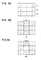
- the magnetic films 11 to 13 in an initial nonrecorded state have unidirectional perpendicular magnetization as shown in Fig. 3A.
- a data bit or a data magnetic domain B M is formed with the magnetization directionally reverse to the initial state, as shown in Fig. 3B.
- a laser beam L B is irradiated to the date magnetic domain B M as shown in Fig.
- the data reproduced from the magnetic domain B M is outputted in the form of, for example, a differential change in the Kerr rotation angle, ao that a great output can be obtained.
- the first magnetic film 11 has a function as a reproducing layer to enhance the reproduction output by shrinking or inverting the magnetic domain in the reproducing operation, it becomes possible to obtain a sufficiently great reproduction output despite minimization of the magnetic domain as bit data, hence realizing a higher recording density.
- Fig. 4A shows a relationship between recorded bits B M1 , B M2 ... formed in a guide truck T and laser beam spot L B which has a much larger diameter than the recorded bits.
- Fig. 4A the allow A indicates a moving direction of the magneto-optical recording medium.
- Fig. 4B the solid line shows an output waveform from the magneto-optical recording medium having recorded bits as shown in Fig. 4A with a conventional method without causing expansion or shrinkage of the recorded bits.
- the recorded bits B M1 and B M2 can't be separely reproduced, because signals obtained from each of recorded bits B M1 , B M2 which are indicated by the dotted line, overlaps with each other.
- Fig. 4C shows an output waveform from the magneto-optical recording medium of Fig. 4A, when the recorded bits are expanded upon playback, where the closely provided bits B M1 , B M2 can be separately reproduced.
- Fig. 4D shows an output waveform when the recorded bits are shrinked upon playback.
- the first to third magnetic films 11 to 13 are composed of rare-earth and transition metals and have such ferrimagnetism that the sublattice magnetization of the transition metal and that of the rare-earth metal are directionally opposite to each other, it is necessary to selectively determine the direction of an external magnetic field Hex, which is applied in a reproducing operation, in accordance with whether the sublattice magnetization of the transition metal or that of the rare-earth metal is dominant in each magnetic film.
- the direction of an external bias magnetic field applied in a recording operation is regarded as a reference, and separate considerations are made as to whether the saturation magnetization of the third magnetic film 13, which occurs immediately below the Curie point Tc3 thereof and dominates the recording direction, is in a transition metal sublattice dominant state or a rare-earth sublattice dominant state.
- the demagnetizing field and the stray magnetic field appied to the data magnetic domain B M in the first magnetic film 11 are neglected from the consideration.
- the data-recorded magnetic domain B M can be expanded by applying, in the reproducing operation, an external magnetic field in the same direction as the external magnetic field applied in the recording operation.
- the magnetic domain B M can be expanded by applying, in the reproducing operation, an external magnetic field Hex in the direction reverse to that in the recording mode.
- the bubble magnetic domain B M can be expanded by applying, in the reproducing operation, an external magnetic field Hex in the direction reverse to that in the recording mode.
- the bubble magnetic domain B M can be expanded by applying, in the reproducing operation, an external bias magnetic field Hex in the same direction as in the recording mode.
- the substrate 1 is composed of a transparent material such as glass plate, plastic plate of acrylic resin, polycarbonate resin or the like and, although not shown, track grooves are formed for tracking servo on one side of the substrate with a pitch of, for example, 1.6 ⁇ m.
- a dielectric film 2 composed of Si3N4, first to third magnetic films 11 to 13, and further a protective film 4 are formed sequentially on the substrate 1 by the technique of continuous evaporation or sputtering performed by, for example, a magnetron sputtering apparatus.
- the first magnetic film 11 may be composed of GdCo, GdFeCo, GdFe or the like;
- the second magnetic film 12 may be composed of DyFe, DyFeCo, TbFe or the like; and
- the third magnetic film 13 may be composed of TbFe, TbFe Co, DyFeCo or the like and composition of each layer is selected to give a suitable Tc and Hc characteristics.
- a magneto-optical recording medium known as an optical disc S was produced by sequentially depositing, on a glass substrate having track grooves with a pitch of 1.6 ⁇ m, a dielectric film 2 of Si3N4, a first magnetic film 11 of GdFeCo, a second magnetic film of DyFeCo, a third magnetic film 13 of DyFeCo, and a protective film 4 of Si3N4 in the form of superposed layers with continuous sputtering performed by a magnetron sputtering apparatus.
- Table 1 lists below the respective thicknesses and magnetic characteristics of such magnetic films 11 to 13 as individual layers.
- FeCo rich implies a film where the FeCo sublattice magnetization is dominant at room temperature
- Dy rich implies a film where the Dy sublattice magnetization is dominant at room temperature
- Fig. 6 graphically shows the results of measuring the dependency of the carrier level-to-noise level (C/N) on the recording frequency in the magneto-optical recording medium S of Embodiment 1.
- a solid-line curve represents the characteristic obtained by the use of an objective lens having a numerical aperture N.A. of 0.50 and a pickup with a laser beam wavelength of 780 nm, under the conditions including a pickup linear velocity of 7.5 m/sec, a recording power of 7.0 mW, a recording external magnetic field intensity of 500 (Oe), a reproducing external magnetic field intensity set to zero, and a reproducing power of 3.5 mW.
- N.A. numerical aperture
- a dottedline curve represents the characteristic obtained with a reproducing power of 1.5 mW.
- the reproducing power is set to 1.5 mW as in this example, the frequency dependency of the C/N achieved is the same as that in a conventional optical disc having merely a single layer of TbFeCo as the entire magnetic film. This seems to result from the phenomenon that, with the reproducing power of such a small value, the heating temperature fails to reach the Curie point Tc2 of the second magnetic film 12 and therefore the recorded magnetic domain is not deformed in the reproducing operation.
- the reproducing power is 3.5 mW, in comparison with the above example of 1.5 mW, the C/N is remarkably increased in a range where the magnetic domain length or bit length l is smaller than 0.7 ⁇ m.
- the temperature profile is spread due to the thermal diffusion in the recording medium S, so that the resolution in reproducing the micro data bit (magnetic domain) is deteriorated.
- a steep temperature profile is attainable by performing reproduction with a pulse laser beam of a narrow width at an interval of the frequency corresponding to the minimal bit length.
- a radiation film of high thermal conductivity such as an aluminum film may be deposited on the therd magnetic film 13 (on the reverse side thereof with respect to the side in contact with the second magnetic film 12).
- Fig. 7 graphically shows a characteristic curve representing the relationship between the temperature and the inverse field intensity of the first magnetic film 11 in the magneto-optical recording medium S of the example.
- Fig. 8 graphically shows the results of measuring the dependency of the carrier level-to-noise level (C/N) on the recording frequency in the medium S.
- a solid-line curve represents the characteristic obtained by the use of an objective lens having a numerical aperture N.A.
- a pickup linear velocity of 7.5 m/sec a recording power of 7.0 mW
- a recording external magnetic field having an intensity of 500 (Oe) a reproducing external magnetic field having an intensity of 600 (Oe) and applied in the same direction as the recording external magnetic field
- a reproducing power of 3.5 mW a broken-line curve represents the characteristic obtained with a reproducing power of 1.5 mW.
- the reproducing power is set to 1.5 mW as in this example, the frequency dependency of the C/N achieved is the same as that in a conventional optical disc having merely a single layer of TbFeCo as the entire magnetic film.
- the temperature profile is spread due to the thermal diffusion in the recording medium S, so that the resolution in reproducing the micro data bit (magnetic domain) is deteriorated.
- a steep temperature profile is attainable by performing reproduction with a pulse laser beam of a narrow width at an interval of the frequency corresponding to the minimal bit length.
- a radiation film of high thermal conductivity such as an aluminum film may be deposited on the third magnetic film 13 (on the reverse side thereof with respect to the side in contact with the second magnetic film 12).
- the present invention having a laminous structure of first, second and third magnetic films 11, 12 and 13, such three magnetic films are retained in a magnetically coupled state with one another at normal temperature, and when heated in a reproducing operation, the second magnetic film 12 functions to interrupt the magnetic coupling between the first and third magnetic films 11 and 13, thereby expanding or shrinking the data-recorded magnetic domain of the first magnetic film 11 to consequently improve the resolution S/N (C/N) of the reproduction output, and still the recording state can be held with regard to the third magnetic film 13. Therefore, after termination of the reproduction, the recording state can be restored to eventually ensure the satisfactory reproduction characteristics without impairing repeated reproduction.
- the present invention is capable of providing a sufficiently great reproduction output as mentioned above, it becomes possible to realize dimensional reduction of the data magnetic domains B M to consequently increase the recording density. Besides the above, even in another structure of the magneto-optical recording medium where track grooves are formed in its base, the data magnetic domains B M can still be reduced dimensionally. Therefore, the recording magnetic domains are formable not merely in land portions alone as in any ordinary medium but also in both land portions and track grooves, hence further enhancing the data recording density.
Abstract
Description
- The present invention relates to a method of reproducing a signal from a magneto-optical recording medium by reading out data bits (magnetic domains) through the magneto-optical interaction.
- In a magneto-optical recording/reproducing method which forms data bits or bubble magnetic domains with irradiation of a laser beam to heat a recording medium locally and reads out the signal by utilizing the magneto-optical interaction, it is necessary, for increasing the magneto-optical recording density, to shorten the length of each bit length, i.e. to minimize the data magnetic domain. However, in the ordinary magneto-optical recording/reproducing system known generally, such attempt is limited by the wavelength of the laser beam in a reproducing mode, the numerical aperture of the lens and so forth for ensuring a satisfactory S/N in a reproducing operation. Under the current technical circumstances, for example, it is impossible to read out a data bit (magnetic domain) of 0.2 µm with a laser beam having a spot diameter of 1 µm.
- Accordingly, it is an object of the present invention to provide a method for reproducing signal from a magneto-optical recording medium in which closely provided bits can be separately reproduced, to enable a high density recording.
- It is another object of the present invention to provide a method for reproducing signal from a magneto-optical recording medium to provide an improved signal to noise ratio.
- According to the present invention there is provided a method of reproducing a signal from a magneto-optical recording medium in which the medium is formed of a first magnetic film, a second magnetic film and a third magnetic film magnetically coupled to one another at room temperature TRT, wherein the Curie points Tc1, Tc2 and Tc3 of the first, second and third magnetic films are in the relationship of Tc2 > TRT, TC2 < Tc1, and Tc2 < Tc3, and the coercive force Hc1 of the first magnetic film is sufficiently small in the vicinity of the Curie point Tc2 of the second magnetic film, while the coercive force Hc3 of the third magnetic film is sufficiently greater than a required magnetic field intensity within a temperature range between the room temperature TRT and a predetermined temperature TPB higher than the Curie point Tc2 of the second magnetic film, and in reproducing a signal from the magneto-optical recording medium, the medium is heated to the predetermined temperature TPB to interrupt the magnetic coupling between the first and third magnetic film under an application of magnetic field to cause change of domain size in the first magnetic film.
-
- Fig. 1 schematically shows the structure of a magneto-optical recording medium used in the method of the present invention;
- Figs. 2A through 2D illustrate the states of magnetization obtained by the method of the invention;
- Figs. 3A through 3C illustrate the states of magnetization obtained by another method of the invention;
- Figs. 4A through 4D show the recorded bits on the magneto-optical recording medium and output waveforms;
- Figs. 5A and 5B show the waveform of a reproduction output with the states of magnetization;
- Fig. 6 graphically shows the reproduction characteristic curves in relation to recording frequencies;
- Fig. 7 graphically shows a characteristic curve representing the relationship between the temperature and the inverse field intensity of the magnetic film; and
- Fig. 8 graphically shows the reproduction characteristic curves in relation to recording frequencies.
- The present invention uses a magneto-optical recording medium S having, on its light transmitting
substrate 1 as shown in Fig. 1, a transparentdielectric film 2 formed when necessary to serve as a protective film or interference film, and further having thereon a firstmagnetic film 11, a secondmagnetic film 12 and a thirdmagnetic film 13 which are magnetically coupled to one another at room temperature TRT and have anisotropy perpendicular to the film surface, wherein the respective Curie points Tc1, Tc2 and Tc3 of the first, second and thirdmagnetic films magnetic film 11 is sufficiently small in the vicinity of the Curie point Tc2 of the secondmagnetic film 12, and the coercive force Hc3 of the thirdmagnetic film 13 is sufficiently greater than a required magnetic field intensity within a temperature range from the room temperature TRT and a predetermined temperature TPB higher than the Curie point Tc2 of the secondmagnetic film 12. - And in reproduction of such recording medium, the data bits or the recorded magnetic domains of the first
magnetic film 11 are expanded or shrinked by the combination of a demagnetizing field applied thereto and an external magnetic field applied when necessary at the aforesaid predetermined temperature TPB above the Curie point Tc2 of the secondmagnetic film 12, and then the signal is read out in such state. - If necessary, a surface
protective film 4 is further formed on the thirdmagnetic film 13. - In recording the magneto-optical recording medium S to form data magnetic domains, as generally known, a laser beam is focused and irradiated while a bias magnetic field is applied in the direction reverse to the perpendicular magnetization of the first to third
magnetic films 11 to 13 in the initial state, whereby the first to thirdmagnetic films 11 to 13 are heated above the respective Curie points. And in the cooling stage posterior to scanning with the laser beam, a bubble magnetic domain inverted directionally by the external magnetic field and the stray magnetic field is formed to record, for example, data "1". That is, binary data "1" or "0" is recorded in accordance with the presence or absence of such data bubble magnetic domain. - And particularly in the present invention to read out or reproduce the recorded data from such magneto-optical recording medium S, the medium portion to be read out is heated, with irradiation of a laser beam or the like, up to the predetermined temperature TPB above the Curie point Tc2 of the second
magnetic film 12, so that the mutual magnetic coupling between the first and thirdmagnetic films magnetic film 11 is rendered free from any magnetic restriction of the thirdmagnetic film 13, and the recorded-data magnetic domain is expanded or shrinked by the required magnetic field which corresponds to the sum of a demagnetizing field and an external magnetic field appllied when necessary, and also by the reduction of the coercive force of the firstmagnetic film 11 caused at the temperature TPB. - As hereinafter explained with reference to Figs. 4C and 4D, the output changes during playback operation, due to the expansion or shrinkage of the data bits, the signal can be obtained by differentiation of the output signal propositional to the Kerr rotation angle. In this case two closely recorded data bits can be separately reproduced to enable high density recording.
- Further, if the first
magnetic film 11 is composed of a suitable material adapted to attain a large Kerr rotation angle or Faraday rotation angle, the substantial area of the data magnetic domain can be increased due to the recorded data principally on the firstmagnetic film 11 to consequently provide a greater reproduction output, hence further improving the S/N (C/N). - Since the reproduction is performed in a state where the recorded-data magnetic domain has been expanded with substantial increase of the read magnetic domain area, it becomes possible to increase the reproduction output to eventually enhance the S/N.
- And the read portion of the recording medium is cooled after reproduction of the data with displacement of the irradiation by the scanning laser beam, so that the third
magnetic film 13 of a high coercive force functions as a magnetic recording retainer layer in the process where the first to thirdmagnetic films 11 to 13 are cooled to, e.g. the room temperature TRT, and the resultant magnetization of the thirdmagnetic film 13 acts to magnetize the secondmagnetic film 12 by magnetic coupling, then to magnetize the firstmagnetic film 11 coupled thereto magnetically, whereby the data-bit magnetic domain in the initial recording state is formed again to resume the recording state. - According to the present invention, as described hereinabove, the second
magnetic film 12 serving as an intermediate layer of the magneto-optical recording medium S is selectively placeable in either a magnetically coupled state or a magnetically interrupted state between the first and thirdmagnetic films magnetic film 12 as an intermediate layer magnetically separates the first and thirdmagnetic films magnetic film 11. Therefore, the thirdmagnetic film 13 maintains its function as a magnetic recording retainer layer to retain the magnetization thereof, while the firstmagnetic film 11 exhibits its function as a reproducing layer to provide higher separation of signals to enable high recorded density an enhanced reproduction output when expansion of the magnetic domain occures. Consequently, the recording density can be increased to ensure a sufficient reproduction output despite minimization of the magnetic domain for bit data, whereby a higher density is rendered attainable in the recording. - Now referring to Fig. 2, a description will be given below with regard to the state of magnetization obtained when each of the first to third
magnetic films 11 to 13 is composed of ferromagnetic material. Suppose now that themagnetic films 11 to 13 in an initial nonrecorded state have unidirectional perpendicular magnetizations as shown in Fig. 2A. And when data "1" is recorded, a data bit or a data magnetic domain BM is formed with the magnetization directionally reverse to the initial state, as shown in Fig. 2B. - In reading out the data magnetic domain BM thus formed, a laser beam LB is irradiated to the data magnetic domain BM as shown in Fig. 2C in such a manner that, as described previously, the aforesaid predetermined temperature TPB is obtained in the center, for example, of the irradiated portion. In this stage, the second
magnetic film 12 is heated beyond its Curie point Tc2 so that the magnetism thereof is lost, whereby the magnetic coupling between the first and thirdmagnetic films magnetic film 11, whose coercive force Hc1 is rendered smaller at the temperature TPB, is expanded by the sum of such external magnetic field and the demagnetizing field. - In a state where the laser beam LB is irradiated outside the data magnetic domain BM as shown in Fig. 2D, the temperature rise caused in the data magnetic domain is relatively small, so that there occurs substantially no expansion of the data bit or magnetic domain BM. Thus, it becomes possible to expand merely the data-recorded magnetic domain BM alone existing at the center of the magnetic domains LB in the central area of the laser beam scanning in the reading mode.
- Referring to Fig. 3, a description will be given below with regard to the state of magnetization obtained when each of the first to third
magnetic films 11 to 13 is composed of ferromagnetic material in another example. Suppose now that themagnetic films 11 to 13 in an initial nonrecorded state have unidirectional perpendicular magnetization as shown in Fig. 3A. And when data "1" is recorded, a data bit or a data magnetic domain BM is formed with the magnetization directionally reverse to the initial state, as shown in Fig. 3B. In reading out the data magnetic domain BM thus formed, a laser beam LB is irradiated to the date magnetic domain BM as shown in Fig. 3c in such a manner that, as described previously, the aforesaid predetermined temperature TPB is obtained in the center, for example, of the irradiated portion. In this stage, the secondmagnetic film 12 is heated beyond its Curie point Tc2 so that the magnetism thereof is lost, whereby the magnetic coupling between the first and thirdmagnetic films magnetic film 11, whose coercive force Hc1 is rendered smaller at the temperature TPB, is shrinked to, e.g. a width W2 or is inverted by the combination of such external magnetic field Hex and the demagnetization field. - Accordingly, if the data reproduced from the magnetic domain BM is outputted in the form of, for example, a differential change in the Kerr rotation angle, ao that a great output can be obtained. Since the first
magnetic film 11 has a function as a reproducing layer to enhance the reproduction output by shrinking or inverting the magnetic domain in the reproducing operation, it becomes possible to obtain a sufficiently great reproduction output despite minimization of the magnetic domain as bit data, hence realizing a higher recording density. - Fig. 4A shows a relationship between recorded bits BM1, BM2 ... formed in a guide truck T and laser beam spot LB which has a much larger diameter than the recorded bits.
- In Fig. 4A the allow A indicates a moving direction of the magneto-optical recording medium.
- In Fig. 4B, the solid line shows an output waveform from the magneto-optical recording medium having recorded bits as shown in Fig. 4A with a conventional method without causing expansion or shrinkage of the recorded bits. In this conventional method the recorded bits BM1 and BM2 can't be separely reproduced, because signals obtained from each of recorded bits BM1, BM2 which are indicated by the dotted line, overlaps with each other.
Fig. 4C shows an output waveform from the magneto-optical recording medium of Fig. 4A, when the recorded bits are expanded upon playback, where the closely provided bits BM1, BM2 can be separately reproduced. Fig. 4D shows an output waveform when the recorded bits are shrinked upon playback. - Consequently, when the laser beam scanning is carried out on the magnetic recording medium where data-recorded magnetic domains BM are arrayed at equal intervals as shown in Fig. 5A, its output obtained by reading out the magnetic domain BM comes to have the waveform of Fig. 5B in which a higher level is indicated upward as compared with an ideal demagnetization level in erasing the magnetic domain BM, in case the domain is expanded at playback.
- Practically, when the first to third
magnetic films 11 to 13 are composed of rare-earth and transition metals and have such ferrimagnetism that the sublattice magnetization of the transition metal and that of the rare-earth metal are directionally opposite to each other, it is necessary to selectively determine the direction of an external magnetic field Hex, which is applied in a reproducing operation, in accordance with whether the sublattice magnetization of the transition metal or that of the rare-earth metal is dominant in each magnetic film. - Such determination will now be described below in detail. Relative to the direction of an external magnetic field Hex applied in a reproducing operation, the direction of an external bias magnetic field applied in a recording operation is regarded as a reference, and separate considerations are made as to whether the saturation magnetization of the third
magnetic film 13, which occurs immediately below the Curie point Tc3 thereof and dominates the recording direction, is in a transition metal sublattice dominant state or a rare-earth sublattice dominant state. Here, the demagnetizing field and the stray magnetic field appied to the data magnetic domain BM in the firstmagnetic film 11 are neglected from the consideration. - [1-1] In case the magnetization of the third
magnetic film 13 is in a transition metal sublattice dominant state immediately below the Curie point Tc3: - (1-1a) When the magnetization of the first
magnetic film 11 is in a transition metal sublattice dominant state in the vicinity of the Curie point Tc2 of the secondmagnetic film 12, the data-recorded magnetic domain BM can be expanded by applying, in the reproducing operation, an external magnetic field in the same direction as the external magnetic field applied in the recording operation. - (1-1b) When the magnetization of the first
magnetic film 11 is close to zero in the vicinity of the Curie point Tc2 of the secondmagnetic film 12, the temperature in the reproducing operation is further raised beyond the vicinity of the Curie point Tc2 of the secondmagnetic film 12 so that the magnetization of the firstmagnetic film 11 is placed in a transition metal sublattice dominant state. In this case, the bubble magnetic domain BM can be expanded by applying an external magnetic field Hex in the same direction as in the recording mode. - (1-1c) When the magnetization of the first
magnetic film 11 is in a rare-earth sublattice dominant state in the vicinity of the Curie point Tc2 of the secondmagnetic film 12, the magnetic domain BM can be expanded by applying, in the reproducing operation, an external magnetic field Hex in the direction reverse to that in the recording mode. - [2-1] In case the magnetization of the third
magnetic film 13 is in a rare-earth sublattice dominant state immediately below the Curie point Tc3 thereof: - (1-2a) When the magnetization of the first
magnetic film 11 is in a transition metal sublattice dominant state in the vicinity of the Curie point Tc2 of the secondmagnetic film 12, the bubble magnetic domain BM can be expanded by applying, in the reproducing operation, an external magnetic field Hex in the direction reverse to that in the recording mode. - (1-2b) When the magnetization of the first
magnetic film 11 is close to zero in the vicinity of the Curie point Tc2 of the secondmagnetic film 12, the temperature TPB in the reproducing operation is further raised beyond the vicinity of the Curie point Tc2 of the secondmagnetic film 12 so that the magnetization of the firstmagnetic film 11 is placed in a transition metal sublattice dominant state. In this case, the magnetic domain BM can be expanded by applying an external magnetic field Hex in the direction reverse to that in the recording mode. - (1-2C) When the magnetization of the first
magnetic film 11 is in a rare-earth sublattice dominant state in the vicinity of the Curie point Tc2 of the secondmagnetic film 12, the bubble magnetic domain BM can be expanded by applying, in the reproducing operation, an external bias magnetic field Hex in the same direction as in the recording mode. - [1-2] In case the magnetization of the third
magnetic film 13 is in a transition metal sublattice dominant state immediately below the Curie point Tc3: - (2-1a) When the magnetization of the first
magnetic film 11 is in a transition metal sublattice dominant state in the vicinity of the Curie point Tc2 of the secondmagnetic film 12, the data-recorded magnetic domain BM can be contracted or inverted by applying, in the reproducing operation, an external magnetic field in the direction reverse to that in the recording mode. - (2-1b) When the magnetization of the first
magnetic film 11 is close to zero in the vicinity of the Curie point Tc2 of the secondmagnetic film 12, the temperature in the reproducing operation is further raised beyond the vicinity of the Curie point Tc2 of the secondmagnetic film 12 so that the magnetization of the firstmagnetic film 11 is placed in a transition metal sublattice dominant state. In this case, the bubble magnetic domain BM can be contracted or inverted by applying an external magnetic field Hex in the direction reverse to that in the recording mode. - (2-1C) When the magnetization of the first
magnetic film 11 is in a rare-earth sublattice dominant state in the vicinity of the Curie point Tc2 of the secondmagnetic film 12, the magnetic domain BM can be contracted or reversed by applying, in the reproducing operation, an external magnetic field Hex in the same direction as in the recording mode. - [2-2] In case the magnetization of the third
magnetic film 13 is in a rare-earth sublattice dominant state immediately below the Curie point Tc3 thereof: - (2-2a) When the magnetization of the first
magnetic film 11 is in a transition metal sublattice dominant state in the vicinity of the Curie point Tc2 of the secondmagnetic film 12, the bubble magnetic domain BM can be contracted or inverted by applying, in the reproducing operation, an external magnetic field Hex in the same direction as in the recording mode. - (2-2b) When the magnetization of the first
magnetic film 11 is close to zero in the vicinity of the Curie point Tc2 of the secondmagnetic film 12, the temperature TPB in the reproducing operation is further raised beyond the vicinity of the Curie point Tc2 of the secondmagnetic film 12 so that the magnetization of the firstmagnetic film 11 is placed in a transition metal sublattice dominatnt state. In this case, the magnetic domain BM can be contracted or inverted by applying an external magnetic field Hex in the same direction as in the recording mode. - (2-2c) When the magnetization of the first
magnetic film 11 is in a rare-earth sublattice dominant state in the vicinity of the Curie point Tc2 of the secondmagnetic film 12, the bubble magnetic domain BM can be contracted or inverted by applying, in the reproducing operation, an external bias magnetic field Hex in the direction reverse to that in the recording mode. - The
substrate 1 is composed of a transparent material such as glass plate, plastic plate of acrylic resin, polycarbonate resin or the like and, although not shown, track grooves are formed for tracking servo on one side of the substrate with a pitch of, for example, 1.6 µm. And adielectric film 2 composed of Si₃N₄, first to thirdmagnetic films 11 to 13, and further aprotective film 4 are formed sequentially on thesubstrate 1 by the technique of continuous evaporation or sputtering performed by, for example, a magnetron sputtering apparatus. - The first
magnetic film 11 may be composed of GdCo, GdFeCo, GdFe or the like; the secondmagnetic film 12 may be composed of DyFe, DyFeCo, TbFe or the like; and the thirdmagnetic film 13 may be composed of TbFe, TbFe Co, DyFeCo or the like and composition of each layer is selected to give a suitable Tc and Hc characteristics. In such thirdmagnetic film 13, there are formable magnetic domains BM each having a diameter smaller than 0.1 µm. - A magneto-optical recording medium known as an optical disc S was produced by sequentially depositing, on a glass substrate having track grooves with a pitch of 1.6 µm, a
dielectric film 2 of Si₃N₄, a firstmagnetic film 11 of GdFeCo, a second magnetic film of DyFeCo, a thirdmagnetic film 13 of DyFeCo, and aprotective film 4 of Si₃N₄ in the form of superposed layers with continuous sputtering performed by a magnetron sputtering apparatus. Table 1 lists below the respective thicknesses and magnetic characteristics of suchmagnetic films 11 to 13 as individual layers.TABLE 1 Material Thickness (Å) Curie point (°C) Holding force (KOe) Magnetic film 11GdFeCo 450 >330 0.2 (FeCo rich) Magnetic film 12DyFeCo 100 93 10 (Dy rich) Magnetic film 13DyFeCo 600 195 20 (Dy rich) - In Table 1, "FeCo rich" implies a film where the FeCo sublattice magnetization is dominant at room temperature, and "Dy rich" implies a film where the Dy sublattice magnetization is dominant at room temperature.
- Fig. 6 graphically shows the results of measuring the dependency of the carrier level-to-noise level (C/N) on the recording frequency in the magneto-optical recording medium S of
Embodiment 1. In Fig. 6, a solid-line curve represents the characteristic obtained by the use of an objective lens having a numerical aperture N.A. of 0.50 and a pickup with a laser beam wavelength of 780 nm, under the conditions including a pickup linear velocity of 7.5 m/sec, a recording power of 7.0 mW, a recording external magnetic field intensity of 500 (Oe), a reproducing external magnetic field intensity set to zero, and a reproducing power of 3.5 mW. Also in Fig. 6, a dottedline curve represents the characteristic obtained with a reproducing power of 1.5 mW. When the reproducing power is set to 1.5 mW as in this example, the frequency dependency of the C/N achieved is the same as that in a conventional optical disc having merely a single layer of TbFeCo as the entire magnetic film. This seems to result from the phenomenon that, with the reproducing power of such a small value, the heating temperature fails to reach the Curie point Tc2 of the secondmagnetic film 12 and therefore the recorded magnetic domain is not deformed in the reproducing operation. When the reproducing power is 3.5 mW, in comparison with the above example of 1.5 mW, the C/N is remarkably increased in a range where the magnetic domain length or bit length ℓ is smaller than 0.7 µm. Even when the bit length ℓ is equal to 0.3 µm, a desired signal component is still obtained although the C/N is low. In this case, the external magnetic field Hex was zero at playback, there is a stray field from the area surrounding the data bit. In a range where the bit length ℓ is greater than 0.7 µm, the C/N is reduced to the contrary due to increase of the noise N. It has been confirmed that if the medium portion once reproduced with a power of 3.5 mW is reproduced again, the C/N is resumed regardless of whether the latter reproducing power is 1.5 mW or 3.5 mW. - If the laser beam power is maintained constant during the reproducing operation in
Embodiment 1 mentioned above, the temperature profile is spread due to the thermal diffusion in the recording medium S, so that the resolution in reproducing the micro data bit (magnetic domain) is deteriorated. A steep temperature profile is attainable by performing reproduction with a pulse laser beam of a narrow width at an interval of the frequency corresponding to the minimal bit length. Furthermore, for the purpose of inducing prompt radiation of the thermal energy absorbed into the magnetic film, a radiation film of high thermal conductivity such as an aluminum film may be deposited on the therd magnetic film 13 (on the reverse side thereof with respect to the side in contact with the second magnetic film 12). - Fig. 7 graphically shows a characteristic curve representing the relationship between the temperature and the inverse field intensity of the first
magnetic film 11 in the magneto-optical recording medium S of the example. And Fig. 8 graphically shows the results of measuring the dependency of the carrier level-to-noise level (C/N) on the recording frequency in the medium S. In Fig. 8, a solid-line curve represents the characteristic obtained by the use of an objective lens having a numerical aperture N.A. of 0.50 and a pickup with a laser beam wavelength of 780 nm, under the conditions including a pickup linear velocity of 7.5 m/sec, a recording power of 7.0 mW, a recording external magnetic field having an intensity of 500 (Oe), a reproducing external magnetic field having an intensity of 600 (Oe) and applied in the same direction as the recording external magnetic field, and a reproducing power of 3.5 mW. Also in Fig. 8, a broken-line curve represents the characteristic obtained with a reproducing power of 1.5 mW. When the reproducing power is set to 1.5 mW as in this example, the frequency dependency of the C/N achieved is the same as that in a conventional optical disc having merely a single layer of TbFeCo as the entire magnetic film. This seems to result from the phenomenon that, with the reproducing power of such a small value, the heating temperature fails to reach the Curie point Tc2 of the secondmagnetic film 12 and therefore the recorded magnetic domain is not deformed in the recording operation. When the reproducing power is 3.5 mW, in comparison with the above example of 1.5 mW, the C/N is remarkably increased in a range where the magnetic domain length or bit length ℓ is smaller than 0.7 µm. Even with the bit length ℓ is equal to 0.3 µm, a desired signal component is still obtained although the C/N is low. In a range where the bit length ℓ is greater than 0.7 µm, the C/N is reduced to the contrary due to increase of the noise N. Further in Fig. 8, a one-dot chain line represents the characteristic measured with a reproducing power of 3.5 mW (ℓ < 0.5 µm) and the external magnetic field intensity Hex set to 0 (Oe). As shown, when the bit length ℓ is smaller than 0.5 µm, the C/N obtained with Hex = 600 (Oe) is higher than the ratio with Hex = 0 (Oe). - It has been confirmed that if the medium portion once reproduced with a power of 3.5 mW is reproduced again, the C/N is resumed regardless of whether the latter reproducing power is 1.5 mW or 3.5 mW.
- If the laser beam power is maintained constant during the reproducing operation in Example mentioned above, the temperature profile is spread due to the thermal diffusion in the recording medium S, so that the resolution in reproducing the micro data bit (magnetic domain) is deteriorated. A steep temperature profile is attainable by performing reproduction with a pulse laser beam of a narrow width at an interval of the frequency corresponding to the minimal bit length. Furthermore, for the purpose of inducing prompt radiation of the thermal energy absorbed into the magnetic film, a radiation film of high thermal conductivity such as an aluminum film may be deposited on the third magnetic film 13 (on the reverse side thereof with respect to the side in contact with the second magnetic film 12).
- As described hereinabove, according to the present invention having a laminous structure of first, second and third
magnetic films magnetic film 12 functions to interrupt the magnetic coupling between the first and thirdmagnetic films magnetic film 11 to consequently improve the resolution S/N (C/N) of the reproduction output, and still the recording state can be held with regard to the thirdmagnetic film 13. Therefore, after termination of the reproduction, the recording state can be restored to eventually ensure the satisfactory reproduction characteristics without impairing repeated reproduction. - Furthermore, since the present invention is capable of providing a sufficiently great reproduction output as mentioned above, it becomes possible to realize dimensional reduction of the data magnetic domains BM to consequently increase the recording density. Besides the above, even in another structure of the magneto-optical recording medium where track grooves are formed in its base, the data magnetic domains BM can still be reduced dimensionally. Therefore, the recording magnetic domains are formable not merely in land portions alone as in any ordinary medium but also in both land portions and track grooves, hence further enhancing the data recording density.
Claims (4)
Applications Claiming Priority (4)
| Application Number | Priority Date | Filing Date | Title |
|---|---|---|---|
| JP62301922A JP2805746B2 (en) | 1987-11-30 | 1987-11-30 | Signal reproducing method for magneto-optical recording medium |
| JP301922/87 | 1987-11-30 | ||
| JP301923/87 | 1987-11-30 | ||
| JP30192387A JP2762445B2 (en) | 1987-11-30 | 1987-11-30 | Signal reproducing method for magneto-optical recording medium |
Publications (3)
| Publication Number | Publication Date |
|---|---|
| EP0318925A2 true EP0318925A2 (en) | 1989-06-07 |
| EP0318925A3 EP0318925A3 (en) | 1990-09-26 |
| EP0318925B1 EP0318925B1 (en) | 1994-04-20 |
Family
ID=26562927
Family Applications (1)
| Application Number | Title | Priority Date | Filing Date |
|---|---|---|---|
| EP88119890A Expired - Lifetime EP0318925B1 (en) | 1987-11-30 | 1988-11-29 | Method for optically reproducing a signal from magneto-optical recording medium |
Country Status (4)
| Country | Link |
|---|---|
| US (1) | US5018119A (en) |
| EP (1) | EP0318925B1 (en) |
| KR (1) | KR970002341B1 (en) |
| DE (1) | DE3889203T2 (en) |
Cited By (27)
| Publication number | Priority date | Publication date | Assignee | Title |
|---|---|---|---|---|
| EP0415449A2 (en) * | 1989-08-31 | 1991-03-06 | Sony Corporation | Playback method for magnetooptical recording |
| EP0416656A2 (en) * | 1989-09-08 | 1991-03-13 | Sony Corporation | Magneto-optical playback method |
| EP0462843A2 (en) * | 1990-06-21 | 1991-12-27 | Seiko Epson Corporation | Magneto-optical method and apparatus for recording/reproducing data |
| EP0492553A2 (en) * | 1990-12-27 | 1992-07-01 | Sony Corporation | Magneto-optical recording medium |
| EP0492581A2 (en) * | 1990-12-28 | 1992-07-01 | Sony Corporation | Method of reproduction from magneto-optical recording medium |
| EP0498440A2 (en) * | 1991-02-08 | 1992-08-12 | Sony Corporation | Magneto-optical recording medium |
| EP0498435A2 (en) * | 1991-02-08 | 1992-08-12 | Sony Corporation | Magneto-optical recording medium |
| EP0498459A2 (en) * | 1991-02-08 | 1992-08-12 | Sony Corporation | Magneto-optical medium and recording and/or reproducing apparatus thereof |
| EP0498455A2 (en) * | 1991-02-08 | 1992-08-12 | Sony Corporation | Magneto-optic recording method and magneto-optic recording/reproducing apparatus |
| EP0498461A2 (en) * | 1991-02-08 | 1992-08-12 | Sony Corporation | System and method of reproducing signals recorded on a magneto-optic recording medium |
| EP0499278A2 (en) * | 1991-02-14 | 1992-08-19 | Sony Corporation | Method for recording sector control information on magneto-optical disk |
| EP0513668A1 (en) * | 1991-05-16 | 1992-11-19 | Sony Corporation | Magneto-optical recording medium |
| EP0524745A2 (en) * | 1991-07-08 | 1993-01-27 | Sharp Kabushiki Kaisha | Magneto-optical recording medium whereon recording is carried out with an overwriting function |
| EP0536938A2 (en) * | 1991-10-07 | 1993-04-14 | Canon Kabushiki Kaisha | Magnetooptical recording medium and magnetooptical record/reproducing method |
| US5241520A (en) * | 1990-12-28 | 1993-08-31 | Sony Corporation | System and method of reproducing signals recorded on a magneto-optic recording medium |
| EP0586122A1 (en) * | 1992-09-02 | 1994-03-09 | Sharp Kabushiki Kaisha | Magneto-optical memory device |
| EP0592199A2 (en) * | 1992-10-06 | 1994-04-13 | Sharp Kabushiki Kaisha | Magneto-optical recording medium and method of recording and reproducing using same |
| EP0606155A3 (en) * | 1993-01-07 | 1996-09-11 | Sharp Kk | A magneto-optical recording medium and a method of recording and/or reproducing using the same. |
| US5574703A (en) * | 1990-06-21 | 1996-11-12 | Seiko Epson Corporation | Magneto-optical method and apparatus for recording/reproducing data |
| EP0833317A2 (en) * | 1996-08-27 | 1998-04-01 | Matsushita Electric Industrial Co., Ltd. | Magneto-optical recording medium and readout method of the same |
| US5772856A (en) * | 1992-07-29 | 1998-06-30 | Seiko Epson Corporation | Magneto-optical recording medium and method of manufacturing the same |
| EP0899721A1 (en) * | 1997-02-17 | 1999-03-03 | Seiko Epson Corporation | Magnetic recording method |
| EP0913818A1 (en) * | 1996-07-12 | 1999-05-06 | Hitachi Maxell, Ltd. | Magneto-optical recording medium, its reproducing method and reproducer |
| US5903526A (en) * | 1996-09-20 | 1999-05-11 | Victor Company Of Japan, Ltd. | Magneto-optical recording medium having multiple magnetic layers |
| EP0915462A1 (en) * | 1996-07-12 | 1999-05-12 | Hitachi Maxell, Ltd. | Magneto-optical recording medium, its reproducing method and reproducer |
| EP0974960A1 (en) * | 1997-12-25 | 2000-01-26 | Sanyo Electric Co., Ltd. | Apparatus for reproducing information and method for reproducing information |
| EP0984445A1 (en) * | 1998-01-23 | 2000-03-08 | Sanyo Electric Co., Ltd. | Reproducing method for magneto-optic recording medium, and magneto-optic disk device |
Families Citing this family (22)
| Publication number | Priority date | Publication date | Assignee | Title |
|---|---|---|---|---|
| US5512366A (en) * | 1989-11-14 | 1996-04-30 | Mitsubishi Denki Kabushiki Kaisha | Magneto-optic recording medium and apparatus |
| US5420728A (en) * | 1990-03-24 | 1995-05-30 | Seiko Epson Corporation | Magneto-optical recording medium including a plurality of recording layers having different curie temperatures and method of recording and reading |
| DE69130441T2 (en) * | 1990-08-07 | 1999-04-08 | Hitachi Maxell | Magneto-optical recording medium |
| JP3038853B2 (en) * | 1990-09-13 | 2000-05-08 | 株式会社ニコン | Overwritable magneto-optical recording medium with high-level margin expanded |
| JP2959586B2 (en) * | 1991-02-12 | 1999-10-06 | ソニー株式会社 | Magneto-optical disk playback method |
| US5637411A (en) * | 1991-07-29 | 1997-06-10 | Hitachi Maxell, Ltd. | Magneto-optical recording medium and process for producing the same |
| US5384758A (en) * | 1991-12-02 | 1995-01-24 | Nikon Corporation | Reproduction-only magneto-optical disk with selectively exchange coupled layers, and reproduction method and reproduction apparatus therefor |
| JP3092363B2 (en) | 1992-12-01 | 2000-09-25 | 松下電器産業株式会社 | Magneto-optical recording medium |
| JP2546477B2 (en) * | 1992-12-21 | 1996-10-23 | 日本電気株式会社 | Magneto-optical recording medium, recording / reproducing method and recording / reproducing apparatus thereof |
| JPH06243522A (en) * | 1993-02-16 | 1994-09-02 | Nikon Corp | Magneto-optical disk and its reproducing method |
| JPH06259799A (en) * | 1993-03-04 | 1994-09-16 | Nikon Corp | Method and device for reproducing optical disk |
| EP0618572B1 (en) | 1993-04-02 | 2002-07-03 | Canon Kabushiki Kaisha | Magnetooptical recording medium on which high-density information can be recorded and method of reproducing the recorded information |
| JP3333613B2 (en) * | 1993-12-07 | 2002-10-15 | 株式会社日立製作所 | Optical information recording medium, optical information recording / reproducing method, and optical information recording / reproducing apparatus |
| JP3566743B2 (en) * | 1993-12-13 | 2004-09-15 | Tdk株式会社 | Optical recording medium |
| JP3426034B2 (en) * | 1994-07-20 | 2003-07-14 | シャープ株式会社 | Magneto-optical recording medium, recording / reproducing method, and method of manufacturing magneto-optical recording medium |
| JP3243126B2 (en) * | 1994-08-11 | 2002-01-07 | パイオニア株式会社 | Magneto-optical recording medium |
| US5593790A (en) * | 1994-12-29 | 1997-01-14 | Imation Corp. | Interference super-resolution using two magnetic layer construction |
| US5835105A (en) * | 1995-03-30 | 1998-11-10 | Imation Corp. | Method of optically turning a magneto-optic medium having in order a substrate two dielectric layers, and a thick magneto-optic recording layer, and medium turner by that method |
| JP3445023B2 (en) * | 1995-06-08 | 2003-09-08 | シャープ株式会社 | Magneto-optical recording medium, its reproducing method and recording method |
| US6226233B1 (en) | 1996-07-30 | 2001-05-01 | Seagate Technology, Inc. | Magneto-optical system utilizing MSR media |
| JPH10162443A (en) * | 1996-12-02 | 1998-06-19 | Sanyo Electric Co Ltd | Information reproducing device |
| JP2002319197A (en) * | 2001-04-19 | 2002-10-31 | Matsushita Electric Ind Co Ltd | Magneto-optical recording medium and method for manufacturing the same |
Citations (5)
| Publication number | Priority date | Publication date | Assignee | Title |
|---|---|---|---|---|
| FR1578005A (en) * | 1968-04-25 | 1969-08-14 | ||
| FR2546655A1 (en) * | 1983-05-25 | 1984-11-30 | Sony Corp | MAGNETO-OPTICAL RECORDING MEDIUM AND METHOD OF MANUFACTURING SUCH A MEDIUM |
| EP0180459A2 (en) * | 1984-10-30 | 1986-05-07 | Brother Kogyo Kabushiki Kaisha | Magneto-optical memory medium and apparatus for writing and reading information on and from the medium |
| US4649519A (en) * | 1985-09-30 | 1987-03-10 | International Business Machines Corporation | Self biasing thermal magneto-optic medium |
| EP0258978A2 (en) * | 1986-07-08 | 1988-03-09 | Canon Kabushiki Kaisha | Magnetooptical recording medium allowing overwriting with two or more magnetic layers and recording method utilizing the same |
Family Cites Families (2)
| Publication number | Priority date | Publication date | Assignee | Title |
|---|---|---|---|---|
| JPS62137754A (en) * | 1985-12-09 | 1987-06-20 | Canon Inc | Photomagnetic recording and reproducing system and photomagnetic memory medium used to said recording and reproducing system |
| AU600576B2 (en) * | 1987-04-24 | 1990-08-16 | Sony Corporation | Thermomagnetic recording method applying power modulated laser on a magnetically coupled multi-layer structure of perpendicular anisotropy magnetic film |
-
1988
- 1988-11-29 DE DE3889203T patent/DE3889203T2/en not_active Expired - Lifetime
- 1988-11-29 EP EP88119890A patent/EP0318925B1/en not_active Expired - Lifetime
- 1988-11-29 KR KR1019880015737A patent/KR970002341B1/en not_active IP Right Cessation
- 1988-11-30 US US07/278,011 patent/US5018119A/en not_active Expired - Lifetime
Patent Citations (5)
| Publication number | Priority date | Publication date | Assignee | Title |
|---|---|---|---|---|
| FR1578005A (en) * | 1968-04-25 | 1969-08-14 | ||
| FR2546655A1 (en) * | 1983-05-25 | 1984-11-30 | Sony Corp | MAGNETO-OPTICAL RECORDING MEDIUM AND METHOD OF MANUFACTURING SUCH A MEDIUM |
| EP0180459A2 (en) * | 1984-10-30 | 1986-05-07 | Brother Kogyo Kabushiki Kaisha | Magneto-optical memory medium and apparatus for writing and reading information on and from the medium |
| US4649519A (en) * | 1985-09-30 | 1987-03-10 | International Business Machines Corporation | Self biasing thermal magneto-optic medium |
| EP0258978A2 (en) * | 1986-07-08 | 1988-03-09 | Canon Kabushiki Kaisha | Magnetooptical recording medium allowing overwriting with two or more magnetic layers and recording method utilizing the same |
Non-Patent Citations (1)
| Title |
|---|
| IBM TECHNICAL DISCLOSURE BULLETIN. vol. 10, no. 2, July 1967, NEW YORK US pages 144 - 145; J.S Judge et al: "Magnetic memory device utilising coupled film" * |
Cited By (67)
| Publication number | Priority date | Publication date | Assignee | Title |
|---|---|---|---|---|
| EP0415449A2 (en) * | 1989-08-31 | 1991-03-06 | Sony Corporation | Playback method for magnetooptical recording |
| US5168482A (en) * | 1989-08-31 | 1992-12-01 | Sony Corporation | Magnetooptical recording and playback method employing multi-layer recording medium with record holding layer and playback layer |
| EP0415449A3 (en) * | 1989-08-31 | 1992-04-01 | Sony Corporation | Playback method for magnetooptical recording |
| EP0416656A2 (en) * | 1989-09-08 | 1991-03-13 | Sony Corporation | Magneto-optical playback method |
| EP0416656A3 (en) * | 1989-09-08 | 1991-06-26 | Sony Corporation | Magneto-optical playback method |
| US5357494A (en) * | 1989-09-08 | 1994-10-18 | Sony Corporation | Magneto-optical playback method |
| EP0462843A2 (en) * | 1990-06-21 | 1991-12-27 | Seiko Epson Corporation | Magneto-optical method and apparatus for recording/reproducing data |
| EP0740297A2 (en) * | 1990-06-21 | 1996-10-30 | Seiko Epson Corporation | Magneto-optical method and apparatus for recording/reproducing data |
| US5574703A (en) * | 1990-06-21 | 1996-11-12 | Seiko Epson Corporation | Magneto-optical method and apparatus for recording/reproducing data |
| EP0740297A3 (en) * | 1990-06-21 | 1997-01-22 | Seiko Epson Corp | Magneto-optical method and apparatus for recording/reproducing data |
| EP0462843A3 (en) * | 1990-06-21 | 1992-09-23 | Seiko Epson Corporation | Magneto-optical method and apparatus for recording/reproducing data |
| US5815469A (en) * | 1990-06-21 | 1998-09-29 | Seiko Epson Corporation | Magneto-optical recording device having recording magnetic field in the same direction as reproducing magnetic field |
| EP0492553A2 (en) * | 1990-12-27 | 1992-07-01 | Sony Corporation | Magneto-optical recording medium |
| EP0492553A3 (en) * | 1990-12-27 | 1993-03-17 | Sony Corporation | Magneto-optical recording medium |
| EP0492581A3 (en) * | 1990-12-28 | 1992-08-05 | Sony Corporation | Method of reproduction from magneto-optical recording medium |
| US5241520A (en) * | 1990-12-28 | 1993-08-31 | Sony Corporation | System and method of reproducing signals recorded on a magneto-optic recording medium |
| EP0492581A2 (en) * | 1990-12-28 | 1992-07-01 | Sony Corporation | Method of reproduction from magneto-optical recording medium |
| EP0498435A3 (en) * | 1991-02-08 | 1992-12-09 | Sony Corporation | Magneto-optical recording medium |
| US5208799A (en) * | 1991-02-08 | 1993-05-04 | Sony Corporation | Magneto-optic recording method and magneto-optic recording/reproducing apparatus |
| KR100239812B1 (en) * | 1991-02-08 | 2000-01-15 | 이데이 노부유끼 | Magneto-optic recording method and magneto-optic recording/reproducing apparatus |
| EP0498440A3 (en) * | 1991-02-08 | 1993-01-13 | Sony Corporation | Magneto-optical recording medium |
| EP0788099A1 (en) * | 1991-02-08 | 1997-08-06 | Sony Corporation | System and method of reproducing signals recorded on a magnetooptic recording medium |
| EP0498455A2 (en) * | 1991-02-08 | 1992-08-12 | Sony Corporation | Magneto-optic recording method and magneto-optic recording/reproducing apparatus |
| EP0498459A2 (en) * | 1991-02-08 | 1992-08-12 | Sony Corporation | Magneto-optical medium and recording and/or reproducing apparatus thereof |
| EP0498461A3 (en) * | 1991-02-08 | 1992-12-09 | Sony Corporation | System and method of reproducing signals recorded on a magneto-optic recording medium |
| US5579294A (en) * | 1991-02-08 | 1996-11-26 | Sony Corporation | Magneto-optical medium and recording and/or reproducing apparatus thereof |
| EP0498435A2 (en) * | 1991-02-08 | 1992-08-12 | Sony Corporation | Magneto-optical recording medium |
| EP0498455A3 (en) * | 1991-02-08 | 1992-12-09 | Sony Corporation | Magneto-optic recording method and magneto-optic recording/reproducing apparatus |
| EP0498459A3 (en) * | 1991-02-08 | 1993-10-13 | Sony Corporation | Magneto-optical medium and recording and/or reproducing apparatus thereof |
| EP0498440A2 (en) * | 1991-02-08 | 1992-08-12 | Sony Corporation | Magneto-optical recording medium |
| EP0498461A2 (en) * | 1991-02-08 | 1992-08-12 | Sony Corporation | System and method of reproducing signals recorded on a magneto-optic recording medium |
| US5371722A (en) * | 1991-02-14 | 1994-12-06 | Sony Corporation | Method for recording sector control information on magneto-optical disk |
| EP0499278A3 (en) * | 1991-02-14 | 1993-08-11 | Sony Corporation | Method for recording sector control information on magneto-optical disk |
| EP0499278A2 (en) * | 1991-02-14 | 1992-08-19 | Sony Corporation | Method for recording sector control information on magneto-optical disk |
| EP0715305A2 (en) * | 1991-02-14 | 1996-06-05 | Sony Corporation | Method for recording sector control information on magneto-optical disk |
| EP0715305A3 (en) * | 1991-02-14 | 1997-01-22 | Sony Corp | Method for recording sector control information on magneto-optical disk |
| EP0513668A1 (en) * | 1991-05-16 | 1992-11-19 | Sony Corporation | Magneto-optical recording medium |
| EP0524745A2 (en) * | 1991-07-08 | 1993-01-27 | Sharp Kabushiki Kaisha | Magneto-optical recording medium whereon recording is carried out with an overwriting function |
| EP0524745A3 (en) * | 1991-07-08 | 1994-02-02 | Sharp Kk | Magneto-optical recording medium whereon recording is carried out with an overwriting function |
| EP0536938A3 (en) * | 1991-10-07 | 1993-07-07 | Canon Kabushiki Kaisha | Magnetooptical recording medium and magnetooptical record/reproducing method |
| EP0536938A2 (en) * | 1991-10-07 | 1993-04-14 | Canon Kabushiki Kaisha | Magnetooptical recording medium and magnetooptical record/reproducing method |
| US5450382A (en) * | 1991-10-07 | 1995-09-12 | Canon Kabushiki Kaisha | Magneto-optical recording medium having a layer that retains its state of magnetization regardless of the presence of an external magnetic field, and a recording/reproducing method therefor |
| US5976688A (en) * | 1992-07-29 | 1999-11-02 | Seiko Epson Corporation | Magneto-optical recording medium and method of manufacturing the same |
| US5772856A (en) * | 1992-07-29 | 1998-06-30 | Seiko Epson Corporation | Magneto-optical recording medium and method of manufacturing the same |
| US5631096A (en) * | 1992-09-02 | 1997-05-20 | Sharp Kabushiki Kaisha | Magneto optical memory device |
| EP0586122A1 (en) * | 1992-09-02 | 1994-03-09 | Sharp Kabushiki Kaisha | Magneto-optical memory device |
| EP0592199A2 (en) * | 1992-10-06 | 1994-04-13 | Sharp Kabushiki Kaisha | Magneto-optical recording medium and method of recording and reproducing using same |
| EP0592199A3 (en) * | 1992-10-06 | 1996-05-15 | Sharp Kk | Magneto-optical recording medium and method of recording and reproducing using same |
| EP0606155A3 (en) * | 1993-01-07 | 1996-09-11 | Sharp Kk | A magneto-optical recording medium and a method of recording and/or reproducing using the same. |
| US5648162A (en) * | 1993-01-07 | 1997-07-15 | Sharp Kabushiki Kaisha | Magneto-optical recording medium and a method of recording and/or reproducing using the same |
| US5691963A (en) * | 1993-01-07 | 1997-11-25 | Sharp Kabushiki Kaisha | Magneto-optical recording device using light-modulated technic without an initial magnetic field |
| EP0913818A1 (en) * | 1996-07-12 | 1999-05-06 | Hitachi Maxell, Ltd. | Magneto-optical recording medium, its reproducing method and reproducer |
| EP0913818A4 (en) * | 1996-07-12 | 2001-04-18 | Hitachi Maxell | Magneto-optical recording medium, its reproducing method and reproducer |
| US6424601B1 (en) | 1996-07-12 | 2002-07-23 | Hitachi Maxell, Ltd. | Magneto-optical recording media having an auxiliary magnetic layer |
| EP0915462A1 (en) * | 1996-07-12 | 1999-05-12 | Hitachi Maxell, Ltd. | Magneto-optical recording medium, its reproducing method and reproducer |
| EP0915462A4 (en) * | 1996-07-12 | 2001-09-12 | Hitachi Maxell | Magneto-optical recording medium, its reproducing method and reproducer |
| EP0833317A3 (en) * | 1996-08-27 | 1998-06-24 | Matsushita Electric Industrial Co., Ltd. | Magneto-optical recording medium and readout method of the same |
| US6018511A (en) * | 1996-08-27 | 2000-01-25 | Matsushita Electric Industrial Co., Ltd. | Magneto-optical recording medium and readout method of the same |
| EP0833317A2 (en) * | 1996-08-27 | 1998-04-01 | Matsushita Electric Industrial Co., Ltd. | Magneto-optical recording medium and readout method of the same |
| US5903526A (en) * | 1996-09-20 | 1999-05-11 | Victor Company Of Japan, Ltd. | Magneto-optical recording medium having multiple magnetic layers |
| EP0899721A1 (en) * | 1997-02-17 | 1999-03-03 | Seiko Epson Corporation | Magnetic recording method |
| EP0974960A1 (en) * | 1997-12-25 | 2000-01-26 | Sanyo Electric Co., Ltd. | Apparatus for reproducing information and method for reproducing information |
| EP0974960A4 (en) * | 1997-12-25 | 2006-06-14 | Sanyo Electric Co | Apparatus for reproducing information and method for reproducing information |
| EP0984445A1 (en) * | 1998-01-23 | 2000-03-08 | Sanyo Electric Co., Ltd. | Reproducing method for magneto-optic recording medium, and magneto-optic disk device |
| US6388955B1 (en) | 1998-01-23 | 2002-05-14 | Sanyo Electric Co., Ltd. | Reproducing method for magneto-optic recording medium, and magneto-optic disk device |
| US6650599B2 (en) | 1998-01-23 | 2003-11-18 | Sanyo Electric Co., Ltd. | Method and apparatus for determining power level of laser beam in magneto-optical recording device |
| EP0984445A4 (en) * | 1998-01-23 | 2006-07-05 | Sanyo Electric Co | Reproducing method for magneto-optic recording medium, and magneto-optic disk device |
Also Published As
| Publication number | Publication date |
|---|---|
| EP0318925A3 (en) | 1990-09-26 |
| KR970002341B1 (en) | 1997-03-03 |
| EP0318925B1 (en) | 1994-04-20 |
| KR890008761A (en) | 1989-07-12 |
| DE3889203D1 (en) | 1994-05-26 |
| US5018119A (en) | 1991-05-21 |
| DE3889203T2 (en) | 1994-11-03 |
Similar Documents
| Publication | Publication Date | Title |
|---|---|---|
| EP0318925B1 (en) | Method for optically reproducing a signal from magneto-optical recording medium | |
| EP0415449B1 (en) | Playback method for magnetooptical recording | |
| EP0492553B1 (en) | Magneto-optical recording medium | |
| JP2805746B2 (en) | Signal reproducing method for magneto-optical recording medium | |
| EP0319004B1 (en) | Magneto-optical recording medium | |
| CA2060548C (en) | Magneto-optical recording medium | |
| US5175714A (en) | Method of magneto-optically recording/erasing information and magneto-optical information storage medium including recording and bias layers satisfying certain conditions | |
| US6226234B1 (en) | Magneto-optic recording medium and reproducing method for reproducing magnetic domain in enlarged form on a reproducing layer | |
| EP0658890A2 (en) | Magnetooptical recording medium with overwrite capabilities and method for using the same | |
| CA1315880C (en) | Method for reproducing signal from magneto-optical recording medium | |
| JP3585671B2 (en) | Magneto-optical recording medium and reproducing method thereof | |
| EP0668585B1 (en) | Information recording method and system using a magneto-optical medium | |
| KR100757815B1 (en) | Magnetooptic recording medium and reproducing method and device therefor | |
| JPH04255941A (en) | Magneto-optical recording medium | |
| JP3412879B2 (en) | Magneto-optical recording medium | |
| US6770387B2 (en) | Magneto-optical recording medium and method of reproducing the same | |
| EP0684600A1 (en) | Magneto-optical recording medium and reproducing method therefor | |
| JP2888218B2 (en) | Magneto-optical recording medium | |
| JP3164058B2 (en) | Method and apparatus for reproducing signal from magneto-optical recording medium | |
| JP2805145B2 (en) | Method of reproducing signal from optical recording medium | |
| JP3428573B2 (en) | Signal reproducing device for magneto-optical recording medium | |
| JP3460685B2 (en) | Magneto-optical recording medium | |
| JPH1139737A (en) | Magneto-optical recording medium and its recording/ reproducing method | |
| JP2001093201A (en) | Magneto-optical recording medium | |
| JPH09171645A (en) | Magneto-optical recording medium |
Legal Events
| Date | Code | Title | Description |
|---|---|---|---|
| PUAI | Public reference made under article 153(3) epc to a published international application that has entered the european phase |
Free format text: ORIGINAL CODE: 0009012 |
|
| AK | Designated contracting states |
Kind code of ref document: A2 Designated state(s): DE FR GB |
|
| PUAL | Search report despatched |
Free format text: ORIGINAL CODE: 0009013 |
|
| AK | Designated contracting states |
Kind code of ref document: A3 Designated state(s): DE FR GB |
|
| 17P | Request for examination filed |
Effective date: 19901220 |
|
| 17Q | First examination report despatched |
Effective date: 19920508 |
|
| GRAA | (expected) grant |
Free format text: ORIGINAL CODE: 0009210 |
|
| AK | Designated contracting states |
Kind code of ref document: B1 Designated state(s): DE FR GB |
|
| REF | Corresponds to: |
Ref document number: 3889203 Country of ref document: DE Date of ref document: 19940526 |
|
| ET | Fr: translation filed | ||
| PLBE | No opposition filed within time limit |
Free format text: ORIGINAL CODE: 0009261 |
|
| STAA | Information on the status of an ep patent application or granted ep patent |
Free format text: STATUS: NO OPPOSITION FILED WITHIN TIME LIMIT |
|
| 26N | No opposition filed | ||
| REG | Reference to a national code |
Ref country code: GB Ref legal event code: IF02 |
|
| PGFP | Annual fee paid to national office [announced via postgrant information from national office to epo] |
Ref country code: DE Payment date: 20071122 Year of fee payment: 20 |
|
| PGFP | Annual fee paid to national office [announced via postgrant information from national office to epo] |
Ref country code: FR Payment date: 20071108 Year of fee payment: 20 Ref country code: GB Payment date: 20071128 Year of fee payment: 20 |
|
| REG | Reference to a national code |
Ref country code: GB Ref legal event code: PE20 Expiry date: 20081128 |
|
| PG25 | Lapsed in a contracting state [announced via postgrant information from national office to epo] |
Ref country code: GB Free format text: LAPSE BECAUSE OF EXPIRATION OF PROTECTION Effective date: 20081128 |