EP0318465A1 - Metering pump with pumping bellows for bottles or same - Google Patents
Metering pump with pumping bellows for bottles or same Download PDFInfo
- Publication number
- EP0318465A1 EP0318465A1 EP89100629A EP89100629A EP0318465A1 EP 0318465 A1 EP0318465 A1 EP 0318465A1 EP 89100629 A EP89100629 A EP 89100629A EP 89100629 A EP89100629 A EP 89100629A EP 0318465 A1 EP0318465 A1 EP 0318465A1
- Authority
- EP
- European Patent Office
- Prior art keywords
- pot
- cap
- pump according
- dosing pump
- bellows
- Prior art date
- Legal status (The legal status is an assumption and is not a legal conclusion. Google has not performed a legal analysis and makes no representation as to the accuracy of the status listed.)
- Granted
Links
Images


Classifications
-
- B—PERFORMING OPERATIONS; TRANSPORTING
- B05—SPRAYING OR ATOMISING IN GENERAL; APPLYING FLUENT MATERIALS TO SURFACES, IN GENERAL
- B05B—SPRAYING APPARATUS; ATOMISING APPARATUS; NOZZLES
- B05B11/00—Single-unit hand-held apparatus in which flow of contents is produced by the muscular force of the operator at the moment of use
- B05B11/01—Single-unit hand-held apparatus in which flow of contents is produced by the muscular force of the operator at the moment of use characterised by the means producing the flow
- B05B11/10—Pump arrangements for transferring the contents from the container to a pump chamber by a sucking effect and forcing the contents out through the dispensing nozzle
- B05B11/1028—Pumps having a pumping chamber with a deformable wall
- B05B11/1035—Pumps having a pumping chamber with a deformable wall the pumping chamber being a bellow
-
- B—PERFORMING OPERATIONS; TRANSPORTING
- B05—SPRAYING OR ATOMISING IN GENERAL; APPLYING FLUENT MATERIALS TO SURFACES, IN GENERAL
- B05B—SPRAYING APPARATUS; ATOMISING APPARATUS; NOZZLES
- B05B11/00—Single-unit hand-held apparatus in which flow of contents is produced by the muscular force of the operator at the moment of use
- B05B11/0005—Components or details
- B05B11/0037—Containers
- B05B11/0039—Containers associated with means for compensating the pressure difference between the ambient pressure and the pressure inside the container, e.g. pressure relief means
- B05B11/0044—Containers associated with means for compensating the pressure difference between the ambient pressure and the pressure inside the container, e.g. pressure relief means compensating underpressure by ingress of atmospheric air into the container, i.e. with venting means
-
- B—PERFORMING OPERATIONS; TRANSPORTING
- B05—SPRAYING OR ATOMISING IN GENERAL; APPLYING FLUENT MATERIALS TO SURFACES, IN GENERAL
- B05B—SPRAYING APPARATUS; ATOMISING APPARATUS; NOZZLES
- B05B11/00—Single-unit hand-held apparatus in which flow of contents is produced by the muscular force of the operator at the moment of use
- B05B11/01—Single-unit hand-held apparatus in which flow of contents is produced by the muscular force of the operator at the moment of use characterised by the means producing the flow
- B05B11/10—Pump arrangements for transferring the contents from the container to a pump chamber by a sucking effect and forcing the contents out through the dispensing nozzle
- B05B11/1042—Components or details
- B05B11/1059—Means for locking a pump or its actuation means in a fixed position
-
- B—PERFORMING OPERATIONS; TRANSPORTING
- B05—SPRAYING OR ATOMISING IN GENERAL; APPLYING FLUENT MATERIALS TO SURFACES, IN GENERAL
- B05B—SPRAYING APPARATUS; ATOMISING APPARATUS; NOZZLES
- B05B11/00—Single-unit hand-held apparatus in which flow of contents is produced by the muscular force of the operator at the moment of use
- B05B11/01—Single-unit hand-held apparatus in which flow of contents is produced by the muscular force of the operator at the moment of use characterised by the means producing the flow
- B05B11/10—Pump arrangements for transferring the contents from the container to a pump chamber by a sucking effect and forcing the contents out through the dispensing nozzle
- B05B11/1042—Components or details
- B05B11/1043—Sealing or attachment arrangements between pump and container
- B05B11/1046—Sealing or attachment arrangements between pump and container the pump chamber being arranged substantially coaxially to the neck of the container
- B05B11/1047—Sealing or attachment arrangements between pump and container the pump chamber being arranged substantially coaxially to the neck of the container the pump being preassembled as an independent unit before being mounted on the container
Definitions
- the invention relates to a metering pump that can be placed in particular on bottles or the like, according to the preamble of the main claim.
- the object of the invention is to provide a generic metering pump with a simple construction and assembly technology that is stable in use, so that the guiding stability is obtained from components of the metering pump that are present anyway.
- a generic pump which is characterized by a simple, stable construction.
- the relatively thin-walled pump bellows is simply inserted freely between two components of the pump housing that are in contact with one another. There is no tilting of the pump bellows and a corresponding displacement of the mouthpiece which affects the accuracy of the output more.
- the pump bellows itself forms the return spring. Specifically, the procedure is such that the mouthpiece-side valve closure body sits in the ceiling of a cap that overlaps the pump bellows, the side wall of which leads to the wall of a pot surrounding the pump bellows, in the bottom of which the inflow-side valve closure body sits.
- the inner surface of the side wall leads on the wall formed by the outer surface of the pot. It also proves to be advantageous in terms of allocation that a screw-on part of the metering pump attaches to the underside of the base and that a riser pipe connection tube with a valve closure body arranged in it is centrally located. The screw-on part also provides an extended guide surface for the axially displaceable cap.
- the foot support ring on the pot base fulfills a further function in that it covers an air inlet opening of the pot base in the manner of a sealing lip and, for this purpose, rests on the inner wall of the pot with a free-standing lip section.
- the lip section acts like a valve, which is why an acute-angled contact is made.
- At least the mouthpiece-side valve closure body has horn-like protruding spring tongues which are supported on the underside of an actuating surface of the cap, which actuating surface overlaps the ceiling of the cap with an axial distance. It can be a plug-in part, which is held by means of the clip connection.
- the procedure is such that retaining lugs for capturing this valve closure body are assigned to the upper edge of the connecting tube hole receiving the bottom valve closure body. In this way, the relocation of the Valve closure body limited in its open position.
- the invention also proposes that the pump bellows be designed as a threaded bellows. This can therefore be created as a precision part, as is not possible, for example, in the blowing process. There is also no need to work with a disintegrating mandrel; rather, the mandrel can simply be unscrewed. Effective locking can also be achieved with structurally simple means by rotating the two pump parts relative to one another. So accidental touches can not lead to a spreading of the filling contents. Prior to this, the willful, pump-oriented alignment of the pot and cap is required.
- the outer surface of the pot has grooves and ribs on the entire circumference in an even distribution, only a fraction of which in the longitudinal direction upwards is open, namely those that are in one rotational stop position in front of the ribs of the cap.
- the rotational stop position is formed by lugs of the pot which abut against the side flanks of the ribs of the cap. In this respect, these ribs even have an additional function; they form the counter-stop for the noses, which can be taken into account when spraying the pot.
- the procedure is simple in that the cap can be rotated into a collar of the pump bellows with a central connecting piece which accommodates the valve body intervenes.
- an advantageous embodiment is realized by several pairs of ribs provided in an angularly symmetrical arrangement on the inner surface of the cap. The impact load is distributed over a corresponding number of surfaces. This has the advantage that the rib height is very low can be worked.
- the cap leads on the inner wall of the pot, the side wall continues in fingers, which penetrate slots under the bottom and reach under it, and in the pump movement in Drive in a space formed between the wall of the pot and the bottle neck, below which free space the pot is attached to the bottle neck.
- the anchoring-like composite zone of the pump parts thus extends outside the bottle neck and is easily reached through fingers of the cap that pass through slots in the bottom.
- the latter have, according to the guided assignment of the cap on the inner wall of the pot, a correspondingly precise alignment, so that there is always an exact grip on the bottom.
- the fingers When stepped into the anchoring position, the fingers secure the pump assembly containing the equipment, such as the bellows, the valve body, etc., of which the bellows, which also acts as a spring body, presses the cap back into the pump-ready position.
- the space for the fingers during pumping movement is between the wall of the pot and the bottle neck in the most economical way.
- the fastening point between the bottle neck and the pot of the dosing pump At the lower end of the free space is the fastening point between the bottle neck and the pot of the dosing pump.
- the free space is advantageously designed by narrowing the cross section of the bottle neck towards its upper end. The pot can thus continue downwards beyond its section forming the guide, so that there is a constant gripping area for the holding hand.
- the radially outwardly resilient fingers engage under the floor with radially inwardly directed locking lugs.
- the escape space for the fingers which spring out correspondingly during assembly is achieved simply by displacing these fingers radially inwards relative to the guided outer wall of the cap or by removing the back of the fingers.
- the locking can be reversible or irreversible. An irreversible installation would be preferred for disposable pumps. Instead of directly engaging behind the locking lugs, the fingers can one Reach in between the sealing ring lying between the bottom and the end of the bottle neck.
- the procedure is further advantageously such that a radially outward-pointing, beak-like mouthpiece of the cap rotatable to the pot lies in the pump-ready position above an entry niche in the pot wall. If the mouthpiece is not in congruent alignment with the entry niche mentioned, the cap cannot be axially displaced in the sense of the execution of the pumping movement.
- the procedure is then simply that a locking projection from the lower edge of the side wall of the cap which can be rotated to the pot goes in the same direction with the fingers, which is in the pump-ready position above an opening in the floor and in its locking position hits the floor.
- the locking projection is formed by a widening in the attachment area of the finger and the opening by a partial section of the slot.
- the metering pump 1 is screwed onto the neck 2 of a bottle 3. Their external thread bears the reference number 4. The internal thread which can be brought into engagement with this is designated by 5.
- the metering pump is fastened by clipping.
- the neck 2 has an annular groove 2 '.
- An annular rib 41 of the pump body engages in this.
- the annular groove 2 ' is an upstream slope 42 formed by a frustoconical wall portion of the neck 2 formed upstream.
- the screw-on or top part 6 of the metering pump 1 starts below the horizontal bottom 7 of a pot 8. The latter points upwards with its opening.
- the latter is overlaid on the top by a cap 9 which, according to the first exemplary embodiment, runs on the pot 8.
- the upper end of the pump bellows B is supported on the ceiling 10 of the pot 8.
- the end edge 8 'of the pot 8 extends at a distance x to the underside of the ceiling 10, which in the pressure actuation position (see Fig. 2) indirectly the stroke limit stop for in the direction of the base of the bottle forms cap 9 displaceable against spring action.
- the return spring is formed by the pump bellows B itself.
- the basic position of the dosing pump is stop-defined.
- the cap 9 forms an inwardly directed annular collar 11 at its lower edge.
- the latter snaps behind a pot-side shoulder 12 at the level of the bottom 7 of the pot 8.
- the lower section of the pot forming the screw-on part 6 springs back slightly in cross-section.
- Its cylindrical outer surface has an axial length which corresponds at least to that of the distance x, so that the outer surface is available as an additional guide surface for the cap 9.
- the cap 9 runs in the pot 8.
- the end edge 9 ⁇ of the cap 9 extends at a distance x from the top of the base 7. This distance corresponds to the actuation stroke, so that the limitation results therefrom for the cap 9 which can be displaced in the direction of the base of the bottle against spring action.
- the return spring forms the pump bellows B itself.
- the basic position of the metering pump 1 which also forms the pump-ready position is also stop-defined. For this purpose, fingers FG start from the cylindrical side wall of the cap 9 guided in the pot 8.
- the floor 7 has slots 43, the lower, inner edge of which is gripped by the fingers FG in the basic position, either directly or indirectly.
- the restoring force of the bellows B holds the fingers FG in the form of locking lugs 44 directed radially inwards. So that the fingers FG or their detents 44 carrying free ends can overrun the outward-facing inner flank of the slots 43 with sufficient avoidance play when the latch is crossed, the slots 43 have a radial width corresponding to the latching head, ie. H.
- each finger FG has a run-on slope 45, so that the locking lugs 44 can be more easily pushed out of their axial extension position during assembly, in order to then undertake the corresponding slot edge.
- a sealing ring 47 is interposed between the underside of the base 7 and the bottle neck end edge 46.
- the latter has a triangular cross section.
- the longer side of the triangle forms a flat, conical sealing flank, which, however, adjoins the cylindrical, cross-sectionally tapered portion that adjoins the run-up slope 42 Exceeds section to the outside, so that the required possibility of reaching under the locking lugs 44 is given.
- the front edge 46 converges upwards on both sides.
- the upper region of the bottle neck 2 close to the end edge is thinner than the lower region.
- an inward bead-like thickening 48 Between this and the ramp section 42 forming the wall portion of the bottle neck 2 is an inward bead-like thickening 48. The latter works together with the annular groove 2 'forming, inwardly curved edge part stiffening the entire neck portion.
- the detents 44 When the pump is actuated, which is done by pressing the cap 9 downward, the detents 44 lift off from the bottom or the sealing ring 47 on the underside; they deflect into an annular free space 49 formed between the pot wall in the area of the top part 6 and the bottle neck 2 and concentric about the longitudinal central axis y-y of the pump body 1. Its axial length is dimensioned so that the fingers FG can retract freely.
- the attachment point between the bottle neck 2 and the pot 8 extends at a sufficient distance below the required actuation stroke.
- the free space 49 is formed by the aforementioned cross-sectional tapering of the bottle neck 2 in the region of its upper end.
- the bottom 7 forms a connecting tube 13 arranged centrally for fitting a riser pipe 14.
- the latter extends to just before the bottom of the bottle 3, so it is immersed in the liquid medium 15 to be dispensed in a very long way.
- the connecting tube 13 has a diameter which still leaves a sufficient annular space between its jacket wall, which is slightly offset in the central region, and the bottle opening 16, into which the connecting tube 13 thus projects freely.
- the upper, somewhat widened half of the connecting tube 13 contains an axially guided valve closure body 17, the top of which lying, flat frustoconical plate 17 'occurs in the closed position against a valve seat surface 18 of the through hole in the bottom 7. Following the tightly fitting plate rim, the flat frustoconical portion of the plate 17' jumps back from the connecting tube inner wall and sits in a cross-profiled Valve plug body guide shaft 19 continues.
- retaining lugs 20 for capturing the valve closure body 17, which is thus axially displaceable to a limited extent.
- the holding lugs 20 are molded onto the base 7 in the same way. In general, two holding lugs 20 arranged diametrically opposite one another are sufficient. However, three holding lugs 20 which are arranged in the same angular distribution to one another are expediently preferred.
- the vertical nasal passages deviate from 17 when the clips are assigned.
- the second of the two valve closure bodies 21 arranged in the region of the ends of the pump bellows B is located in the cover 10 of the cap 9.
- the latter is of the same construction as the valve closure body 17, which is why the reference numbers are transferred analogously, without text repetition. The only difference is that it is not held in its closed position depending on the weight, but is in this direction under spring load.
- two spring tongues 22 extend from the top of the plate. The latter are horn-like in shape, ie they diverge and end in an outward curve. These rounded end portions come against the underside 23 'of an actuating surface 23 of the cap 9.
- the actuating surface 23 indented in FIG. 2 from the top overlaps the ceiling 10 of the cap 9 at an axial distance.
- the actuating surface 23 is formed from the bottom part of a pot-shaped plug-in part 24, which is clipped like a lid into an extension 25 of the cap 9.
- the clip zone carries that Reference numeral 24 '.
- An irreversible clip assignment is preferably used.
- the collar-like, correspondingly upwardly open extension 25 of the cap 9 forms, together with the plug-in part 24, directed radially outward, a beak-like mouthpiece 26, the channel 27 of which is fluidly connected to a chamber 28 realized in the region of the extension 25.
- connection piece 29 projecting into the interior of the pump bellows B.
- the latter has an axial length such that in the pump actuation position it remains at a sufficient distance from the retaining lugs 20 (see FIG. 2). .
- the end folds 30 of the pump bellows B each sit on a collar 31 of the base 7 or the cover 10 (FIG. 10). Both collars 31 extend concentrically to the longitudinal center axis yy of the metering pump. The end folds 30 of both ends then continue in foot support rings 32.
- the foot support ring 32 On the pot bottom side, the foot support ring 32 has a further function. This overlaps one or more air inlet openings 35 in the bottom 7 of the pot 8. It has a sealing lip function and, with its free-standing lip section 32 ', rests elastically on the corresponding inner wall 8 Topf of the pot.
- the circumferential lip portion 32 In order to replace the volume of air corresponding to the amount dispensed, the circumferential lip portion 32 'lifts off the inner wall of the pot 8 ′′′ during the suction stroke of the pump bellows, so that air flows into the interior of the bottle via the joint F between the pot 8 and the cap 9 in the direction of the arrow z can occur. In the basic position, however, the lip portion 32 'returns to its sealing position shown in FIG. 1. Since said lip portion 32 'extends in an obliquely sloping orientation and when the pump bellows compresses a tilting moment in the direction of the inner wall 8 innen of the fold end point, the corresponding sealing system is also mechanically favored, especially since Pump bellows is also used with a slight preload.
- Such a valve function of the lip portion 32 prevents the medium 15 from escaping when the bottle has fallen over or from entering the free, annular space-like environment of the pump bellows.
- the lower edge of the end fold 30 there of the pump bellows B lifts off from the air inlet opening 35 on the upper side.
- the collar 31, which is only realized here below, is concentrically surrounded by a second collar 52, which likewise extends from the top of the base. Between the two collars 31, 52 extends an annular groove 53. In the latter protrudes a forked ring-lip portion of the pump bellows B.
- the one annular lip portion 32 ⁇ sealingly comprises the outside of the cylindrical collar 31.
- the other circumferential lip portion 32 'exercises the sealing lips described above - or valve function off.
- the reference numbers are used accordingly.
- Pot 8 and cap 9 of the metering pump can be rotated to a limited extent relative to one another in the expansion position of pump bellows B, that is to say in the basic position shown in FIG. 1.
- the correspondingly rotationally symmetrical design of the pump-forming components results from FIGS. 3 and 4.
- the cap 9 is brought into an operational readiness position or into a locking position.
- the rotary stops for both end positions are formed by lugs 36. The latter, as can be clearly seen in FIGS. 5-9, from the upper end edge 8 'of the pot 8.
- the pairs of ribs extend in an angularly symmetrical arrangement on the inner surface 9 'of the cap 9.
- the angular distance is 120 °.
- the corresponding multiplication of the stops brings the advantage of a low rib height, since the stop pressure is distributed over several surfaces. Pot and cap can therefore be kept very thin-walled.
- the ribs 37 run in the axial direction of the metering pump and interact with correspondingly aligned grooves 38 on the corresponding lateral surface 8 ⁇ of the pot 8.
- the grooves 38 at least also realized in pairs, i.e. H. their inlet cross-section for the ribs 37 is brought from the congruent position by relative rotation of one or the other pump part, i.e. the pot 8 or the cap 9, so that in front of the lower end face 37 'of the inlet 37 the ribs 37 instead of the groove 38 of the closed pot rim , So the end face 8 'of the pot 8 extends.
- the corresponding blocking if the pot rim is not closed, can of course also be caused by the corresponding end faces of the ribs 39 left between the grooves 38 of the lateral surface of the pot 8 or the screw-on part 6 which adjoins downwards be taken over.
- the stop lugs 36 must be arranged accordingly.
- the path of rotation must at least correspond to the clear width of a groove or a multiple of this width.
- the latching can be between initiate the collar 11 of the cap 9 and the shoulder 12 of the pot 8 cheaper.
- the level is less difficult.
- the annular collar can also be formed by webs of the same angular distribution projecting into the circular cavity of the cap 9 in a secant manner.
- an embodiment is made such that the cap 9, with its central socket 29 supporting the valve body 21, rotatably engages in a collar 40 of the pump bellows B concentrically surrounding this socket.
- the corresponding wrap at the same time takes into account the need for a seal between the media-carrying area of the metering pump and the bellows-surrounding annular space area, which is used for air compensation.
- the stop-limited rotation angle displacement of the cap is defined by the slots 43, which, as can be seen from FIG. 11, are realized as circular arc slots.
- An adjustment range of approximately 90 ° is selected in which end positions the side flanks of the fingers FG strike at one or the other end of the slot 43.
- the mouthpiece 26 of the cap 9 rotatable in the pot 8 extends in the pump-ready position exactly above an entry niche 50 of the pot wall.
- the outer cross-sectional dimension of the mouthpiece 26 is matched to the width of the niche, as is the depth thereof to the stroke dimension x.
- a configuration can also be made such that a locking projection 51 extends in the same direction with the fingers FG from the lower edge or end edge 9 ⁇ of the side wall of the rotatable cap 9.
- the locking projection 51 can be free-standing to the fingers or can be a component this be.
- Fig. 12 where the mentioned locking projections 51 are shown. 11, which has the type of locking explained in detail above, these locking projections 51 are shown in dash-dotted lines for better understanding, although it is a structurally different embodiment.
- the locking projections 51 lie with their lower edge 51 'pointing in the direction of the bottom 7' above an opening in the bottom 7; in the locking position, on the other hand, they extend in a rotation angle range in which they abut the floor 7 from above.
- the recognizable axial cut back of the fingers FG corresponds to the stroke dimension x.
- the locking projection 51 formed by a widening in the attachment area of the fingers FG cooperates with an opening which, when the locking projection 51 is free-standing, is formed separately, or is otherwise formed by a partial section of the slots 43, so that no separate openings are required. This widening of the fingers FG results in a larger, stabilizing material accumulation, seen in the circumferential direction, the enlarged arch section also proving to be favorable.
- valve closure body 17 lying in the bottom 7 lifts off from its valve seat surface 18.
- the next metered filling quantity is drawn into the bellows body via the riser pipe 14.
- the corresponding suction force, supported by the spring tongues 22, holds the upper valve closure body 21 in the closed position.
- the dispensing volume is compensated for by air which can penetrate into the bottle space via the air inlet opening 35 in the manner described above.
- the metering pump is locked again by relative rotation between the cap and the pot, the ribs 37 emerging from the area of the continuously open grooves 38 and with their ends 37 'blocking the front wall 8'.
- the metering pump 1 can be locked again after use by relative rotation between the cap 9 and the pot 8, but either the underside of the mouthpiece 26 overlaps the upper rim of the pot, or the locking projections 51, leaving the passage area, the top 7 blocking overlay.
- the mere frictional force between the two parts 8 and 9 secures this stop-defined basic position completely adequately, although latching means (not shown in more detail here) could also be used.
- the material to be dispensed can still be flowable or even pasty, e.g. B. toothpaste.
Abstract
Description
Die Erfindung bezieht sich auf eine insbesondere auf Flaschen oder dergleichen aufsetzbare Dosierpumpe gemäß Gattungsbegriff des Hauptanspruches.The invention relates to a metering pump that can be placed in particular on bottles or the like, according to the preamble of the main claim.
Bekannt sind Dosierpumpen mit freistehendem Pumpenbalg. Letzterer muß außergewöhnlich standstabil und daher sehr dickwandig ausgebildet sein. Das bedeutet Materialaufwand und bringt eine erschwerte Bedienung, vor allem für Kinder und ältere Menschen. Andererseits gibt es Pumpenkolben mit sich aneinander führenden Bauteilen.Dosing pumps with free-standing pump bellows are known. The latter must be exceptionally stable and therefore very thick-walled. This means expenditure of material and makes operation more difficult, especially for children and the elderly. On the other hand, there are pump pistons with components that come together.
Aufgabe der Erfindung ist es, eine gattungsgemäße Dosierpumpe in herstellungs- und montagetechnisch einfacher, gebrauchsstabiler Bauform so auszubilden, daß die Führungsstabilität von ohnehin vorhandenen Bauteilen der Dosierpumpe gewonnen wird.The object of the invention is to provide a generic metering pump with a simple construction and assembly technology that is stable in use, so that the guiding stability is obtained from components of the metering pump that are present anyway.
Gelöst ist diese Aufgabe durch die im Anspruch 1 angegebene Erfindung.This object is achieved by the invention specified in
Die Unteransprüche sind vorteilhafte Weiterbildungen der erfindungsgemäßen Dosierpumpe.The subclaims are advantageous developments of the metering pump according to the invention.
Zufolge solcher Ausgestaltung ist eine gattungsgemäße Pumpe geschaffen, die sich durch gebrauchsstabilen, einfachen Aufbau auszeichnet. Der relativ dünnwandig ausführbare Pumpenbalg ist einfach frei zwischen zwei sich aneinander führenden Bauteilen des Pumpengehäuses eingesetzt. Es kommt zu keinem Verkippen des Pumpenbalges und einer dementsprechenden, die Zielgenauigkeit der Ausgabe beeinträchtigenden Verlagerung des Mundstückes mehr. Der Pumpenbalg selbst bildet die Rückstellfeder. Konkret ist so vorgegangen, daß der mundstückseitige Ventilverschlußkörper in der Decke einer den Pumpenbalg überfangenden Kappe sitzt, deren Seitenwand sich an der Wandung eines den Pumpenbalg umfassenden Topfes führt, in dessen Boden der zuflußseitige ventilverschlußkörper sitzt. Dabei ist es günstig, daß die Innenfläche der Seitenwand sich auf der von der Mantelfläche des Topfes gebildeten Wandung führt. Weiter erweist es sich zuordnungstechnisch als vorteilhaft, daß unterseitig des Bodens ein Aufschraubteil der Dosierpumpe ansetzt und zentral ein Steigrohr-Anschlußröhrchen mit in diesem angeordnetem Ventilverschlußkörper liegt. Der Aufschraubteil bringt überdies eine verlängerte Führungsfläche für die axial verlagerbare Kappe. Zur Fixierung des Pumpenbalges ist es günstig, daß die Endfalten des Pumpenbalges auf je einem Kragen sitzen und sich in auswärts gerichtet abstehende Fußstützringe fortsetzen; über die so vergrößerte Stützringfläche erfüllt der topfbodenseitige Fußstützring noch eine weitere Funktion insofern, als er eine Lufteinlaßöffnung des Topfbodens dichtlippenartig überfängt und dazu mit einem freistehenden Lippenabschnitt an der Topfinnenwand anliegt. Der Lippenabschnitt wirkt ventilartig, weshalb eine spitzwinklige Anlage vorgenommen ist. Beim Saughub des Pumpenbalges hebt sich der Lippenabschnitt von der Topfwand ab, so daß der Luftausgleich über die Fuge der sich führenden Pumpengehäuseteile stattfinden kann. Mindestens der mundstückseitige Ventilverschlußkörper besitzt hörnerartig vorstehende Federzungen, die sich an der Unterseite einer Betätigungsfläche der Kappe abstützen, welche Betätigungsfläche die Decke der Kappe mit axialem Abstand überfängt. Es kann sich hier um ein Steckteil handeln, welches im Wege der Klipsverbindung gehalten wird. Um die Lage des anderen Ventilkörpers zu sichern, ist so vorgegangen, daß dem oberen Rand des den bodenseitigen Ventilverschlußkörper aufnehmenden Anschlußröhrchen-Loches Haltenasen zur Fesselung dieses Ventilverschlußkörpers zugeordnet sind. Auf diese Weise wird mit einfachen Mitteln die Verlagerung des Ventilverschlußkörpers in seine Offenstellung begrenzt. Um zu einer raumsparenden Dosierpumpenform zu gelangen, erweist es sich als vorteilhaft, daß der topfbodenseitige Fußstützring mit axialem Abstand vor der Lufteinlaßöffnung endet. Weiter bringt die Erfindung noch in Vorschlag, daß der Pumpenbalg als Gewindebalg ausgebildet ist. Dieser kann demzufolge als Präzisionsteil erstellt werden, wie dies bspw. im Blasverfahren nicht möglich ist. Auch braucht nicht mit zerfallendem Formkern gearbeitet zu werden; vielmehr läßt sich der Formkern einfach herausschrauben. Auch ist mit baulich einfachen Mitteln durch Drehen der beiden Pumpenteile zueinander eine wirksame Verriegelung erreichbar. So können zufällige Berührungen nicht zu einem Ausbringen des Füllinhaltes führen. Es bedarf zuvor der willensbetonten pumpgerechten Ausrichtung von Topf und Kappe. Dabei ist es aus führungstechnischen Gründen und zugleich zur Erzielung einer verbesserten Griffigkeit für die Zuordnung des Topfes am Flaschenhals oder dergleichen günstig, daß die Mantelfläche des Topfes auf dem ganzen Umfang in gleichmäßiger Verteilung Nuten und Rippen aufweist, von denen nur ein Bruchteil in Längsrichtung nach oben hin offen ist, und zwar diejenigen, die in der einen Dreh-Anschlagstellung vor den Rippen der Kappe liegen. Zudem erweist es sich als vorteilhaft, daß die Dreh-Anschlagstellung von Nasen des Topfes gebildet ist, welche gegen die Seitenflanken der Rippen der Kappe anschlagen. Diesen Rippen kommt insofern sogar eine Zusatzfunktion zu; sie bilden nämlich den Gegenanschlag für die Nasen, welche sich beim Spritzen des Topfes gleich mitberücksichtigen lassen. Um den Pumpenbalg in seiner funktionsgerechten Lage zu halten, so daß die Drehbewegung von Topf und Kappe nicht zu einem Verwürgen des Pumpenbalges führt, ist in einfacher Weise so vorgegangen, daß die Kappe mit einem zentralen, den Ventilkörper aufnehmenden Stutzen in einen Kragen des Pumpenbalges drehbar eingreift. Weiter ist eine vorteilhafte Ausgestaltung durch mehrere in winkelsymmetrischer Anordnung vorgesehene Rippenpaare an der Innenfläche der Kappe realisiert. Die Anschlagbelastung verteilt sich auf entsprechend viele Flächen. Dies hat den Vorteil, daß mit einer sehr geringen Rippenhöhe gearbeitet werden kann. Im Hinblick auf die Pumpenmontage und die Zuordnung zur Flasche oder dergleichen besteht eine vorteilhafte Weiterbildung dahingehend, daß die Kappe sich an der Innenwand des Topfes führt, sich die Seitenwand in Finger fortsetzt, welche Schlitze des Bodens durchsetzen und diesen untergreifen, und bei der Pumpbewegung in einen zwischen Topfwandung und Flaschenhals gebildeten Freiraum einfahren, unterhalb welches Freiraumes der Topf zum Flaschenhals hin befestigt ist. Die verankerungsartige Verbundzone der Pumpenteile erstreckt sich so außerhalb des Flaschenhalses und ist einfach über Schlitze des Bodens durchgreifende Finger der Kappe erreicht. Letztere besitzen zufolge der geführten Zuordnung der Kappe an der Innenwand des Topfes eine entsprechend präzise Ausrichtung, so daß stets ein exakter bodenseitiger Untergriff gegeben ist. In die Verankerungsstellung getreten, sichern die Finger die das Eingerichte, wie den Balg, die Ventilkörper etc. enthaltende Pumpaggregat, von welchen Eingerichtteilen der Balg, zugleich als Federkörper fungierend, auch hier die Kappe in die Pump-Bereitschaftsstellung zurückdrückt. Der Ausweichraum für die Finger bei Pumpbewegung liegt raumgünstigst zwischen Topfwandung und Flaschenhals. Am unteren Ende des Freiraumes befindet sich die Befestigungsstelle zwischen Flaschenhals und Topf der Dosierpumpe. In vorteilhafter Weise ist der Freiraum durch Querschnittsverjüngung des Flaschenhalses zu seinem oberen Ende hin gestaltet. Der Topf kann sich so über seinen die Führung bildenden Abschnitt hinaus nach unten hin unterbrechungsfrei fortsetzen, so daß ein gleichbleibender Greifbereich für die Haltehand vorliegt. Weiter erweist es sich als vorteilhaft, daß die radial auswärts federbaren Finger den Boden mit radial einwärts gerichteten Rastnasen untergreifen. Der Ausweichraum für die bei Montage entsprechend ausfedernden Finger ist einfach durch radial einwärts gerichteten Versatz dieser Finger gegenüber der geführten Mantelwand der Kappe erreicht oder durch Abtrag des Fingerrückens. Die Verrastung kann reversibel oder irreversibel sein. Für Einwegpumpen würde einer irreversiblen Montage der Vorzug gegeben. Statt eines unmittelbaren Hintergriffs der Rastnasen können die Finger einen zwischen Boden und Flaschenhals-Stirnrand liegenden Dichtungsring untergreifen. Zur Definition der Pump-Bereitschaftsstellung gegenüber einer Verriegelungsstellung wird weiter in vorteilhafter Weise so vorgegangen, daß ein radial auswärts gerichtetes, schnabelartiges Mundstück der zum Topf drehbaren Kappe in Pump-Bereitschaftsstellung oberhalb einer Eintrittsnische der Topfwand liegt. Befindet sich das Mundstück nicht in kongruenter Ausrichtung zur genannten Eintrittsnische, so ist die Kappe nicht im Sinne der Ausführung der Pumpbewegung axial verlagerbar. Wird einer der Sicht völlig entzogenen Verriegelungsvorrichtung der Vorzug gegeben, bei der also eine Eintrittsnische am Topf, bspw. aus ästhetischen Gründen, nicht ausgebildet sein soll, so wird dann einfach so verfahren, daß vom unteren Rand der Seitenwand der zum Topf drehbaren Kappe ein Riegelvorsprung gleichgerichtet mit den Fingern ausgeht, der in Pump-Bereitschaftsstellung oberhalb einer Durchbrechung des Bodens liegt und in seiner Verriegelungsstellung gegen den Boden stößt. In vorteilhafter Ausgestaltung ist der Riegelvorsprung jedoch von einer Verbreiterung im Ansatzbereich des Fingers und die Durchbrechung von einem Teilabschnitt des Schlitzes gebildet. Endlich bringt die Erfindung noch in Vorschlag, daß ein gegabelter Ring-Lippenabschnitt des Pumpenbalges in einer Ringnut des Topfbodens einliegt, von welchem die Lufteinlaßöffnung durch den Boden hindurch ausgeht. Hierdurch ist die diesbezügliche Ventilfunktion optimiert.As a result of such an embodiment, a generic pump is created which is characterized by a simple, stable construction. The relatively thin-walled pump bellows is simply inserted freely between two components of the pump housing that are in contact with one another. There is no tilting of the pump bellows and a corresponding displacement of the mouthpiece which affects the accuracy of the output more. The pump bellows itself forms the return spring. Specifically, the procedure is such that the mouthpiece-side valve closure body sits in the ceiling of a cap that overlaps the pump bellows, the side wall of which leads to the wall of a pot surrounding the pump bellows, in the bottom of which the inflow-side valve closure body sits. It is advantageous that the inner surface of the side wall leads on the wall formed by the outer surface of the pot. It also proves to be advantageous in terms of allocation that a screw-on part of the metering pump attaches to the underside of the base and that a riser pipe connection tube with a valve closure body arranged in it is centrally located. The screw-on part also provides an extended guide surface for the axially displaceable cap. To fix the pump bellows, it is expedient for the end folds of the pump bellows to sit on a collar and to continue in foot support rings projecting outwards; Via the enlarged support ring surface, the foot support ring on the pot base fulfills a further function in that it covers an air inlet opening of the pot base in the manner of a sealing lip and, for this purpose, rests on the inner wall of the pot with a free-standing lip section. The lip section acts like a valve, which is why an acute-angled contact is made. During the suction stroke of the pump bellows, the lip section lifts off the wall of the pot, so that the air balance can take place over the joint of the leading pump housing parts. At least the mouthpiece-side valve closure body has horn-like protruding spring tongues which are supported on the underside of an actuating surface of the cap, which actuating surface overlaps the ceiling of the cap with an axial distance. It can be a plug-in part, which is held by means of the clip connection. In order to secure the position of the other valve body, the procedure is such that retaining lugs for capturing this valve closure body are assigned to the upper edge of the connecting tube hole receiving the bottom valve closure body. In this way, the relocation of the Valve closure body limited in its open position. In order to achieve a space-saving metering pump shape, it proves to be advantageous that the foot support ring on the pot bottom ends with an axial distance in front of the air inlet opening. The invention also proposes that the pump bellows be designed as a threaded bellows. This can therefore be created as a precision part, as is not possible, for example, in the blowing process. There is also no need to work with a disintegrating mandrel; rather, the mandrel can simply be unscrewed. Effective locking can also be achieved with structurally simple means by rotating the two pump parts relative to one another. So accidental touches can not lead to a spreading of the filling contents. Prior to this, the willful, pump-oriented alignment of the pot and cap is required. It is for management reasons and at the same time to achieve an improved grip for the assignment of the pot to the bottle neck or the like that the outer surface of the pot has grooves and ribs on the entire circumference in an even distribution, only a fraction of which in the longitudinal direction upwards is open, namely those that are in one rotational stop position in front of the ribs of the cap. In addition, it proves to be advantageous that the rotational stop position is formed by lugs of the pot which abut against the side flanks of the ribs of the cap. In this respect, these ribs even have an additional function; they form the counter-stop for the noses, which can be taken into account when spraying the pot. In order to keep the pump bellows in its functional position so that the rotary movement of the pot and cap does not lead to gagging of the pump bellows, the procedure is simple in that the cap can be rotated into a collar of the pump bellows with a central connecting piece which accommodates the valve body intervenes. Furthermore, an advantageous embodiment is realized by several pairs of ribs provided in an angularly symmetrical arrangement on the inner surface of the cap. The impact load is distributed over a corresponding number of surfaces. This has the advantage that the rib height is very low can be worked. With regard to the pump assembly and the assignment to the bottle or the like, there is an advantageous development in that the cap leads on the inner wall of the pot, the side wall continues in fingers, which penetrate slots under the bottom and reach under it, and in the pump movement in Drive in a space formed between the wall of the pot and the bottle neck, below which free space the pot is attached to the bottle neck. The anchoring-like composite zone of the pump parts thus extends outside the bottle neck and is easily reached through fingers of the cap that pass through slots in the bottom. The latter have, according to the guided assignment of the cap on the inner wall of the pot, a correspondingly precise alignment, so that there is always an exact grip on the bottom. When stepped into the anchoring position, the fingers secure the pump assembly containing the equipment, such as the bellows, the valve body, etc., of which the bellows, which also acts as a spring body, presses the cap back into the pump-ready position. The space for the fingers during pumping movement is between the wall of the pot and the bottle neck in the most economical way. At the lower end of the free space is the fastening point between the bottle neck and the pot of the dosing pump. The free space is advantageously designed by narrowing the cross section of the bottle neck towards its upper end. The pot can thus continue downwards beyond its section forming the guide, so that there is a constant gripping area for the holding hand. It also proves to be advantageous that the radially outwardly resilient fingers engage under the floor with radially inwardly directed locking lugs. The escape space for the fingers which spring out correspondingly during assembly is achieved simply by displacing these fingers radially inwards relative to the guided outer wall of the cap or by removing the back of the fingers. The locking can be reversible or irreversible. An irreversible installation would be preferred for disposable pumps. Instead of directly engaging behind the locking lugs, the fingers can one Reach in between the sealing ring lying between the bottom and the end of the bottle neck. To define the pump-ready position in relation to a locking position, the procedure is further advantageously such that a radially outward-pointing, beak-like mouthpiece of the cap rotatable to the pot lies in the pump-ready position above an entry niche in the pot wall. If the mouthpiece is not in congruent alignment with the entry niche mentioned, the cap cannot be axially displaced in the sense of the execution of the pumping movement. If a locking device which is completely hidden from view is preferred, in which an entry niche on the pot should not be formed, for example for aesthetic reasons, the procedure is then simply that a locking projection from the lower edge of the side wall of the cap which can be rotated to the pot goes in the same direction with the fingers, which is in the pump-ready position above an opening in the floor and in its locking position hits the floor. In an advantageous embodiment, however, the locking projection is formed by a widening in the attachment area of the finger and the opening by a partial section of the slot. Finally, the invention proposes that a forked ring-lip portion of the pump bellows lies in an annular groove in the pot base, from which the air inlet opening extends through the base. As a result, the relevant valve function is optimized.
Der Gegenstand der Erfindung ist nachstehend anhand zweier zeichnerisch veranschaulichter Ausführungsbeispiele näher erläutert. Es zeigt
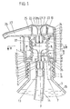
- Fig. 1 die auf einen Flaschenhals aufgeschraubte Dosierpumpe gemäß dem ersten Ausführungsbeispiel im Vertikalschnitt, und zwar in ihrer federbelasteten Grundstellung und unverriegelt,
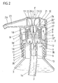
- Fig. 2 eine der Fig. 1 entsprechende Darstellung, jedoch in Pumpbetätigungsstellung, also komprimiertem Pumpenbalg,
- Fig. 3 den Schnitt gemäß Linie III-III in Fig. 1, und zwar bei entferntem Pumpenbalg,
- Fig. 4 eine der Fig. 3 entsprechende Schnittdarstellung, jedoch in Verriegelungsstellung,
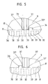
- Fig. 5 eine Ansicht gegen die die Verriegelungsstellung bringenden Mittel, in vergrößerter Wiedergabe und in Betätigungsbereitschaftsstellung der Kappe,
- Fig. 6 eine der Fig. 5 entsprechende Darstellung, jedoch in anschlagdefinierter Verriegelungsstellung,
- Fig. 7 die Dosierpumpe in aufgebrochener Seitenansicht in der Stellung gemäß Fig. 1,
- Fig. 8 die erfindungsgemäße Flasche mit aufsitzender Dosierpumpe gemäß dem zweiten Ausführungsbeispiel in Seitenansicht,
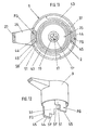
- Fig. 9 die Draufsicht hierzu,
- Fig. 10 den Schnitt gemäß Linie X-X in Fig. 9, und zwar in gegenüber Fig. 9 vergrößerter Wiedergabe,
- Fig. 11 den Schnitt gemäß Linie XI-XI in Fig. 10 und
- Fig. 12 die Kappe in perspektivischer Einzeldarstellung unter Verdeutlichung einer abgewandelten Verriegelungsvorrichtung.
- 1 the metering pump screwed onto a bottle neck according to the first embodiment in vertical section, specifically in its spring-loaded basic position and unlocked,
- 2 shows a representation corresponding to FIG. 1, but in the pump actuation position, that is to say compressed pump bellows,
- 3 shows the section along line III-III in FIG. 1, with the pump bellows removed,
- 4 is a sectional view corresponding to FIG. 3, but in the locked position,
- 5 is a view against the means bringing the locking position, in an enlarged representation and in the ready-to-operate position of the cap,
- 6 is a representation corresponding to FIG. 5, but in the stop-defined locking position,
- 7 the dosing pump in a broken side view in the position according to FIG. 1,
- 8 shows the side view of the bottle according to the invention with a metering pump according to the second exemplary embodiment,
- 9 is a top view of this,
- 10 shows the section along line XX in FIG. 9, namely in an enlarged representation compared to FIG. 9,
- Fig. 11 shows the section along line XI-XI in Fig. 10 and
- Fig. 12, the cap in a perspective individual illustration, illustrating a modified locking device.
Die Dosierpumpe 1 ist gemäß dem ersten Ausführungsbeispiel auf den Hals 2 einer Flasche 3 aufgeschraubt. Deren Außengewinde trägt das Bezugszeichen 4. Das damit in Eingriff bringbare Innengewinde ist mit 5 bezeichnet.According to the first exemplary embodiment, the
Die Befestigung der Dosierpumpe geschieht beim zweiten Ausführungsbeispiel durch Verklipsen. Der Hals 2 weist dazu eine Ringnut 2′ auf. In diese greift eine Ringrippe 41 des Pumpenkörpers ein. Zum erleichterten Eintritt der Ringrippe ist der Ringnut 2′ eine von einem kegelstumpfförmig verlaufenden Wandungsabschnitt des Halses 2 gebildete Auflaufschräge 42 vorgelagert.In the second embodiment, the metering pump is fastened by clipping. The
Der Aufschraub- oder Aufsatzteil 6 der Dosierpumpe 1 setzt unterhalb des horizontalen Bodens 7 eines Topfes 8 an. Letzterer weist mit seiner Öffnung nach oben.The screw-on or
Der Topf 8 nimmt, konzentrisch darin eingelagert, einen Pumpenbalg B auf. Letzterer ist oberseitig von einer Kappe 9 überfangen, die gemäß dem ersten Ausführungsbeispiel auf dem Topf 8 läuft. An der Decke 10 des Topfes 8 stützt sich das obere Ende des Pumpenbalges B ab. In Grundstellung (Fig. 1) der Dosierpumpe erstreckt sich der Stirnrand 8′ des Topfes 8 in einem Abstand x zur Unterseite der Decke 10, die in der Druckbetätigungsstellung (vergl. Fig. 2) mittelbar den Hubbegrenzungsanschlag für die in Richtung der Standfläche der Flasche entgegen Federwirkung verlagerbaren Kappe 9 bildet. Deren Innenfläche 9′ führt sich auf der von der Mantelfläche des Topfes 8 gebildeten Wandung 8˝. Die Rückstellfeder bildet der Pumpenbalg B selbst.The
Die Grundstellung der Dosierpumpe ist anschlagdefiniert. Hierzu bildet die Kappe 9 an ihrem unteren Rand einen einwärts gerichteten Ringbund 11 aus. Letzterer schnappt hinter eine topfseitige Schulter 12 auf Höhe des Bodens 7 des Topfes 8. Der den Aufschraubteil 6 bildende untere Abschnitt des Topfes springt dazu querschnittsmäßig leicht zurück. Seine zylindrische Mantelfläche weist eine axiale Länge auf, die mindestens dem des Abstandes x entspricht, so daß die Mantelfläche als zusätzliche Führungsfläche für die Kappe 9 zur Verfügung steht.The basic position of the dosing pump is stop-defined. For this purpose, the
Gemäß dem zweiten Ausführungsbeispiel führt sich die Kappe 9 im Topf 8. In Pump-Bereitschaftsstellung der Dosierpumpe 1 erstreckt sich der Stirnrand 9˝ der Kappe 9 in einem Abstand x zur Oberseite des Bodens 7. Dieser Abstand entspricht dem Betätigungshub, so daß hieraus die Begrenzung für die in Richtung der Standfläche der Flasche entgegen Federwirkung verlagerbare Kappe 9 resultiert. Deren Mantelfläche 9′ führt sich auf der Innenfläche 8‴ des Topfes 8. Die Rückstellfeder bildet der Pumpenbalg B selbst. Die zugleich die Pump-Bereitschaftsstellung bildende Grundstellung der Dosierpumpe 1 ist ebenfalls anschlagdefiniert. Hierzu gehen von der zylindrischen Seitenwand der im Topf 8 geführten Kappe 9 Finger FG aus. Letztere entspringen dem Stirnrand 9˝ der Kappe 9 und setzen sich in Erstreckungsrichtung der Seitenwand der Kappe 9 fort, und zwar in Richtung der Standfäche der Flasche bzw. in Richtung des Bodens 7, welchen sie durchsetzen. Der Boden 7 besitzt dazu Schlitze 43, deren untere, innere Randkante von den Fingern FG in Grundstellung mittel- oder unmittelbar untergriffen wird. Die Rückstellkraft des Balges B hält den Fingern FG radial einwärts gerichtet angeformte Rastnasen 44 in Anlage. Damit die Finger FG bzw. ihre Rastnasen 44 tragenden freien Enden bei Rastübertritt die auswärts weisende Innenflanke der Schlitze 43 mit genügendem Ausweichspiel überlaufen können, besitzen die Schlitze 43 eine dem Rastkopf entsprechende radiale Breite, d. h. sie springen gegenüber der Innenwand des zylindrischen Topfes 8 um das Maß des Nasenvorsprunges zurück. Der Nasenrücken eines jeden Fingers FG weist eine Auflaufschräge 45 auf, so daß die Rastnasen 44 bei der Montage leichter aus ihrer axialen Erstreckungslage herausgedrängt werden können, um anschließend den korrespondierenden Schlitzrand zu unterfangen.According to the second embodiment, the
Wie Fig. 10 entnehmbar ist zwischen der Unterseite des Bodens 7 und dem Flaschenhals-Stirnrand 46 ein Dichtungsring 47 zwischengelegt. Letzterer besitzt dreieckigen Querschnitt. Die längere Dreieckseite formt eine flach konische Dichtungsflanke, welche aber den an die Auflaufschräge 42 anschließenden zylindrischen, querschnittsverjüngten Abschnitt nach außen hin überragt, so daß die erforderliche Untergreifmöglichkeit der Rastnasen 44 gegeben ist. Der Stirnrand 46 konvergiert beidseitig nach oben hin. Der obere stirnrandnahe Bereich des Flaschenhalses 2 ist gegenüber dem unteren Bereich wandungsdünner ausgebildet. Zwischen diesem und dem die Auflaufschräge 42 bildenden Wandungsabschnitt des Flaschenhalses 2 liegt eine nach innen gerichtete wulstartige Verdickung 48. Letztere wirkt zusammen mit der die Ringnut 2′ formenden, einwärts gewölbten Randpartie für den gesamten Halsabschnitt versteifend.As can be seen in FIG. 10, a sealing
Bei Betätigung der Pumpe, was unter Abwärtsdrücken der Kappe 9 geschieht, heben sich die Rastnasen 44 vom Boden bzw. dem Dichtring 47 unterseitig ab; sie weichen in einen zwischen Topfwandung im Bereich des Aufsatzteiles 6 und Flaschenhals 2 gebildeten ringförmigen, konzentrisch um die Längsmittelachse y-y des Pumpenkörpers 1 verlaufenden Freiraum 49 aus. Dessen axiale Lange ist so bemessen, daß die Finger FG frei einfahren können. Die Befestigungsstelle zwischen Flaschenhals 2 und dem Topf 8 erstreckt sich nämlich in genügendem Abstand noch unterhalb des erforderlichen Betätigungshubweges. Gebildet ist der Freiraum 49 durch die erwähnte Querschnittsverjüngung des Flaschenhalses 2 im Bereich seines oberen Endes.When the pump is actuated, which is done by pressing the
Der Boden 7 formt bei beiden Ausführungsbeispielen zentral angeordnet ein Anschlußröhrchen 13 zum Aufstecken eines Steigrohres 14. Letzteres reicht bis kurz vor den Boden der Flasche 3, taucht also auf ganzer Lange in das dosiert auszugebende flüssige Medium 15 ein. Das Anschlußröhrchen 13 besitzt einen Durchmesser, der noch einen genügenden Ringraum zwischen seiner im Mittelbereich leicht abgesetzten Mantelwand und der Flaschenöffnung 16 beläßt, in die das Anschlußröhrchen 13 also frei hineinragt.In both exemplary embodiments, the bottom 7 forms a connecting
Die obere, etwas verbreiterte Hälfte des Anschlußröhrchens 13 enthält einen axial darin geführten Ventilverschlußkörper 17. Dessen oben liegender, flach kegelstumpfförmiger Teller 17′ tritt in Schließstellung gegen eine Ventilsitzfläche 18 des Durchtrittslochs im Boden 7. Im Anschluß an den dichtend anliegenden Tellerrand springt der flach kegelstumpfförmige Abschnitt des Tellers 17′ von der Anschlußröhr-chen-Innenwand zurück und setzt sich in einen kreuzprofilierten Ventilverschlußkörper-Führungsschaft 19 fort.The upper, somewhat widened half of the connecting
Wie der Zeichnung entnehmbar, gehen vom oberen Rand des den bodenseitigen Ventilverschlußkörper 17 aufnehmenden AnschlußröhrchenLoches Haltenasen 20 zur Fesselung des somit begrenzt axial verschieblich angeordneten Ventilverschlußkörpers 17 aus. Die Haltenasen 20 sind dem Boden 7 gleich angeformt. Im allgemeinen reichen zwei, diametral einander gegenüberliegend angeordnete Haltenasen 20 aus. Zweckmäßig werden jedoch drei, in gleicher Winkelverteilung zueinander angeordnete Haltenasen 20 bevorzugt. Die vertikalen Nasenschafte weichen bei Klipszuordnung von 17 aus.As can be seen in the drawing, starting from the upper edge of the connecting tube hole receiving the bottom
Der zweite der beiden im Bereich der Enden des Pumpenbalges B angeordnete Ventilverschlußkörper 21 befindet sich in der Decke 10 der Kappe 9. Letzterer ist gleichen Aufbaues wie der Ventilverschlußkörper 17, weshalb die Bezugsziffern, ohne textliche Wiederholung, sinngemäß übertragen sind. Der einzige Unterschied besteht darin, daß dieser nicht schwergewichtsabhängig in seiner Schließstellung gehalten ist, sondern in dieser Richtung unter Federbelastung steht. Hierzu gehen von der Telleroberseite zwei Federzungen 22 aus. Letztere sind hörnerartiger Gestalt, d. h. sie divergieren und gehen endseitig in eine nach auswärts gerichtete Rundung über. Diese gerundeten Endabschnitte treten gegen die Unterseite 23′ einer Betätigungsfläche 23 der Kappe 9. Die gemäß Fig. 2 von der Oberseite her eingedellte Betätigungsfläche 23 überfängt in axialem Abstand die Decke 10 der Kappe 9. Gebildet ist die Betätigungsfläche 23 von der Bodenpartie eines topfförmigen Steckteils 24, welches deckelartig in einen Fortsatz 25 der Kappe 9 eingeklipst ist. Die Klipszone trägt das Bezugszeichen 24′. Vorzugsweise wird eine irreversible Klipszuordnung angewandt. Der kragenartige, entsprechend nach oben offene Fortsatz 25 der Kappe 9 bildet zusammen mit dem Steckteil 24 quer radial auswärts gerichtet ein schnabelartiges Mundstück 26 aus, dessen Kanal 27 strömungstechnisch mit einer im Bereich des Fortsatzes 25 realisierten Kammer 28 in Verbindung steht.The second of the two
Zur Aufnahme des mundstückseitigen Ventilverschlußkörpers 21 formt die Decke 10 einen in den Innenraum des Pumpenbalges B hineinragenden Stutzen 29. Letzterer weist eine axiale Länge auf derart, daß in der Pumpbetätigungsstellung dieser noch in genügendem Abstand zu den Haltenasen 20 stehenbleibt (vergl. Fig. 2).To accommodate the
Zur Abstützung und am Topf 8 auch zugleich zur Abdichtung und Lagefixierung des Pumpenbalges B sitzen die Endfalten 30 des Pumpenbalges B auf je einem Kragen 31 des Bodens 7 bzw. der Decke 10 (Fig. 10). Beide Kragen 31 erstrecken sich konzentrisch zur Längsmittelachse y-y der Dosierpumpe. Die Endfalten 30 beider Enden setzen sich sodann in Fußstützringe 32 fort. Topfbodenseitig kommt dem Fußstützring 32 eine weitergehende Funktion zu. Dieser überfängt nämlich eine oder mehrere Lufteinlaßöffnungen 35 im Boden 7 des Topfes 8. Er übt Dichtlippenfunktion aus und liegt dazu mit seinem freistehenden Lippenabschnitt 32′ an der korrespondierenden Topfinnenwand 8‴ elastisch an. Um den der Ausgabemenge entsprechenden Volumenanteil an Luft zu ersetzen, hebt sich beim Saughub des Pumpenbalges der umlaufende Lippenabschnitt 32′ von der Topfinnenwand 8‴ ab, so daß über die Fuge F zwischen Topf 8 und Kappe 9 in Richtung des Pfeiles z Luft in den Flascheninnenraum eintreten kann. In Grundstellung hingegen tritt der Lippenabschnitt 32′ wieder in seine aus Fig. 1 ersichtliche dichtende Lage. Da der genannte Lippenabschnitt 32′ in einer schräg abfallenden Ausrichtung verläuft und beim Komprimieren des Pumpenbalges ein Kippmoment in Richtung der Topfinnenwand 8‴ um den Faltenendpunkt entsteht, wird die entsprechende Dichtungsanlage auch noch mechanisch begünstigt, zumal der Pumpenbalg auch mit leichter Vorspannung eingesetzt ist. Eine solche Ventilfunktion des Lippenabschnitts 32′ verhindert es, daß bei umgefallener Flasche Medium 15 austreten bzw. in das freie, ringraumartige Umfeld des Pumpenbalges gelangen kann. Wie Fig. 1 entnehmbar, hebt der untere Rand der dortigen Endfalte 30 des Pumpenbalges B oberseitig von der Lufteinlaßöffnung 35 ab.For support and on the
Gemäß dem zweiten Ausführungsbeispiel ist der hier nur unten realisierte Kragen 31 von einem zweiten Kragen 52 konzentrisch umgeben, welcher ebenfalls von der Oberseite des Bodens ausgeht. Zwischen beiden Kragen 31, 52 erstreckt sich eine Ringnut 53. In letztere ragt ein gegabelter Ring-Lippenabschnitt des Pumpenbalges B. Der eine Ring-Lippenabschnitt 32˝ umfaßt abdichtend außenseitig den zylindrischen Kragen 31. Der andere umlaufende Lippenabschnitt 32′ übt die oben beschriebene Dichtlippen- bzw. Ventilfunktion aus. Die Bezugsziffern sind sinngemäß angewandt.According to the second exemplary embodiment, the
Topf 8 und Kappe 9 der Dosierpumpe sind in Expansionsstellung des Pumpenbalges B, also in der aus Fig. 1 ersichtlichen Grundstellung zueinander anschlagend begrenzt drehbar. Der entsprechend rotationssymmetrisch gewählte Aufbau der pumpenbildenden Bauteile ergibt sich aus den Fig. 3 und 4. Durch Drehen der beiden Pumpenteile zueinander wird die Kappe 9 in eine Betätigungsbereitschaftsstellung oder in eine Verriegelungsstellung gebracht. Dadurch können zufällige Berührungen an der Kappe oder beispielsweise ein kopfübergerichtetes Herunterfallen der Flasche 3 nicht mehr zu einer ungewollten Ausgabe führen. Die Dreh-Anschläge für beide Endstellungen sind von Nasen 36 gebildet. Letztere gehen, wie den Fig. 5 - 9 deutlich entnehmbar, vom oberen Stirnrand 8′ des Topfes 8 aus. Sie ragen mit ihren in Drehrichtung liegenden Stirnkanten in den Bereich von die entsprechenden Gegenanschläge bildenden Rippen 37 der Kappe 9. Sie schlagen je nach Drehrichtung an der einen oder anderen äußeren Seitenflanke dieser paarig angeordneten Rippen an (vergl. Fig. 3 und 4).
Die Rippenpaare erstrecken sich in winkelsymmetrischer Anordnung an der Innenfläche 9′ der Kappe 9. Der Winkelabstand beträgt 120°. Die entsprechende Vervielfachung der Anschläge bringt den Vorteil einer geringen Rippenhöhe, da sich der Anschlagdruck auf mehrere Flächen verteilt. Topf und Kappe können daher sehr dünnwandig gehalten sein.The pairs of ribs extend in an angularly symmetrical arrangement on the inner surface 9 'of the
Die Rippen 37 verlaufen in axialer Richtung der Dosierpumpe und wirken mit ensprechend ausgerichteten Nuten 38 an der korrespondierenden Mantelfläche 8˝ des Topfes 8 zusammen. Die mindestens ebenfalls in paariger Anordnung realisierten Nuten 38, d. h. ihr Eintrittsquerschnitt für die Rippen 37 wird durch Relativverdrehung des einen oder anderen Pumpenteiles, also des Topfes 8 oder der Kappe 9 aus der kongruenten Lage gebracht, so daß sich vor dem eintrittseitigen, unteren Stirnende 37′ der Rippen 37 statt die Nut 38 der geschlossene Topfrand, also die Stirnfläche 8′ des Topfes 8 erstreckt.The
Bei einer durchgehend umlaufenden Rippung, wie sie sich aus Fig. 7 ergibt, kann die entsprechende Sperrung bei nicht zugezogenem Topfrand natürlich auch von den korrespondierenden Stirnflächen der zwischen den Nuten 38 belassenen Rippen 39 der Mantelfläche des Topfes 8 bzw. des nach untenhin anschließenden Aufschraubteils 6 übernommen werden. Die Anschlagnasen 36 müssen entsprechend angeordnet sein. Der Drehweg muß mindestens der lichten Breite einer Nut entsprechen bzw. einem Vielfachen dieser Breite. Durch die entsprechende Verrippung der Mantelfläche des Topfes bzw. des Aufschraubteils ergibt sich nicht nur eine bessere Führung der beiden drehbar zueinander angeordneten pumpenbildenden Teile, sondern auch eine Erhöhung der Griffigkeit für das Auf- bzw. Abschrauben des Topfes 8. Außerdem läßt sich die Verrastung zwischen dem Ringbund 11 der Kappe 9 und der Schulter 12 des Topfes 8 günstiger einleiten. Die Stufe ist weniger hart. Der Ringbund kann auch von in die kreisrunde Höhlung der Kappe 9 sekantenartig vorspringenden Stegen gleicher Winkelverteilung gebildet sein.In the case of a continuous circumferential ribbing, as can be seen in FIG. 7, the corresponding blocking, if the pot rim is not closed, can of course also be caused by the corresponding end faces of the
Wie den Fig. 3 und 4 entnehmbar, ist nur ein Bruchteil der insgesamt auf der Mantelfläche des Topfes 9 realisierten Nuten 38 zur Bildung der Verriegelungsmittel herangezogen, und zwar die, welche in der jeweiligen Dreh-Anschlagstellung vor den paarig angeordneten Rippen 37 der Kappe 9 liegen.As can be seen in FIGS. 3 and 4, only a fraction of the total of the
Um die Drehbewegung der pumpenbildenden Teile nicht auf den Pumpenbalg B zu übertragen, ist eine Ausgestaltung dahingehend getroffen, daß die Kappe 9 mit ihrem zentralen, den Ventilkörper 21 lagernden Stutzen 29 in einen diesen Stutzen konzentrisch umgebenden Kragen 40 des Pumpenbalges B drehbar eingreift. Der entsprechende Umgriff berücksichtigt dabei zugleich das Erfordernis der Abdichtung zwischen dem medienführenden Bereich der Dosierpumpe und dem balgumgebenden Ringraumbereich, der zum Luftausgleich dient.In order not to transmit the rotary movement of the pump-forming parts to the pump bellows B, an embodiment is made such that the
Beim zweiten Ausführungsbeispiel ist die anschlagbegrenzte Drehwinkelverlagerung der Kappe durch die Schlitze 43 definiert, welche, wie aus Fig. 11 ersichtlich, als Kreisbogenschlitze realisiert sind. Dabei ist ein Verstellbereich von ca. 90° gewählt, in welchen Endstellungen die Seitenflanken der Finger FG am einen oder anderen Ende des Schlitzes 43 anschlagen. In der einen Anschlagstellung (Fig. 11 bzw. Fig. 10) erstreckt sich das Mundstück 26 der im Topf 8 drehbaren Kappe 9 in Pump-Bereitschaftsstellung exakt oberhalb einer Eintrittsnische 50 der Topfwandung. Das Außenquerschnittsmaß des Mundstückes 26 ist auf die Breite der Nische abgestimmt, ebenso die Tiefe derselben auf das Hubmaß x.In the second exemplary embodiment, the stop-limited rotation angle displacement of the cap is defined by the
Soll die Ausbildung einer sichtbaren Eintrittsnische 50 an der Topfwandung vermieden werden, so kann auch eine Ausgestaltung dahingehend vorgenommen werden, daß vom unteren Rand bzw. Stirnrand 9˝ der Seitenwand der drehbaren Kappe 9 ein Riegelvorsprung 51 gleichgerichtet mit den Fingern FG ausgeht. Der Riegelvorsprung 51 kann freistehend zu den Fingern ausgebildet sein oder Bestandteil dieser sein. Es wird auf Fig. 12 verwiesen, wo die erwähnten Riegelvorsprünge 51 so wiedergegeben sind. In Fig. 11, welche die oben ausgiebig erläuterte Verriegelungsart zum Gegenstand hat, sind diese Riegelvorsprünge 51 zum besseren Verständnis in strichpunktierter Linienart wiedergegeben, obwohl es sich dort um eine baulich andere Ausgestaltung handelt. In Pump-Bereitschaftsstellung liegen die Riegelvorsprünge 51 mit ihrer in Richtung des Bodens 7 weisenden Unterkante 51′ oberhalb je einer Durchbrechung des Bodens 7; in der Verriegelungsstellung dagegen erstrecken sie sich in einem Drehwinkelbereich, in dem sie von oben her gegen den Boden 7 stoßen. Der erkennbare axiale Zurückschnitt der Finger FG entspricht dem Hubmaß x. Der von einer Verbreiterung im Ansatzbereich der Finger FG gebildete Riegelvorsprung 51 wirkt mit einer Durchbrechung zusammen, die, bei freistehendem Riegelvorsprung 51 separat, oder sonst von einem Teilabschnitt der Schlitze 43 gebildet ist, so daß keine separaten Durchbrechungen erforderlich sind. Durch diese Verbreiterung der Finger FG ergibt sich, in Umfangsrichtung gesehen, eine größere, sie stabilisierende Materialanhäufung, wobei sich auch der vergrößerte Wölbungsabschnitt als günstig erweist.If the formation of a
Die Funktion ist wie folgt:The function is as follows:
Durch Ausübung einer Kraft in Richtung des Pfeiles P auf die Betätigungsfläche 23 wird nach vorheriger Entriegelung der bewegliche Teil der Dosierpumpe 1, also die Kappe 9, geführt nach unten verlagert. Es liegt die in Fig. 2 ersichtliche Stellung vor, in der sich das Volumen im Balg verringert. Das darin befindliche flüssige Medium 15 wird folglich unter Passieren des oberen Ventils unter Anheben des dortigen Ventilverschlußkörpers 21 verdrängt, um über die Kammer 28 in den Mundstückkanal 27 zu gelangen zwecks Ausgabe. Der im Balgraum entstehende Druck schließt dabei den unteren Ventilverschlußkörper 17. Wird nun die Kappe 9 losgelassen, bewirkt der Pumpenbalg B zufolge seiner ihm innewohnenden Rückstellkraft die Herbeiführung der aus Fig. 1 ersichtlichen Grundstellung. Das führt zu einem Saughub. Der im Boden 7 liegende Ventilverschlußkörper 17 hebt von seiner Ventilsitzfläche 18 ab. Über das Steigrohr 14 wird so die nächste dosierte Füllmenge in den Balgkörper gesogen. Die entsprechende Saugkraft, unterstützt durch die Federzungen 22, hält den oberen Ventilverschlußkörper 21 in Schließstellung. Das Ausgabevolumen wird durch Luft, welche in der oben geschilderten Weise über die Lufteinlaßöffnung 35 in den Flaschenraum eindringen kann, ausgeglichen. Nach Gebrauch wird die Dosierpumpe wieder durch Relativverdrehung zwischen Kappe und Topf verriegelt, wobei die Rippen 37 aus dem Bereich der durchgehend offenen Nuten 38 treten und mit ihren Stirnenden 37′ sperrend vor der Stirnwand 8′ stehen. Auch beim zweiten Ausführungsbeispiel kann die Dosierpumpe 1 nach Gebrauch wieder durch Relativverdrehung zwischen Kappe 9 und Topf 8 verriegelt werden, wobei dort aber entweder die Unterseite des Mundstücks 26 den oberen Topfrand sperrend überfängt, oder die Riegelvorsprünge 51, den Durchtrittsbereich verlassend, den Boden 7 oberseitig sperrend überfangen. Die bloße Reibungskraft zwischen den beiden Teilen 8 und 9 sichert diese anschlagdefinierte Grundstellung völlig ausreichend, obwohl hier auch nicht näher dargestellte Rastmittel beigezogen werden könnten.By exerting a force in the direction of arrow P on the
Das Ausgabegut kann aus noch fließfähigem bis sogar pastösem Material, wie z. B. Zahnpasta, bestehen.The material to be dispensed can still be flowable or even pasty, e.g. B. toothpaste.
Alle in der Beschreibung erwähnten und in der Zeichnung dargestellten neuen Merkmale sind erfindungswesentlich, auch soweit sie in den Ansprüchen nicht ausdrücklich beansprucht sind.All the new features mentioned in the description and shown in the drawing are essential to the invention, even if they are not expressly claimed in the claims.
Claims (20)
Priority Applications (2)
| Application Number | Priority Date | Filing Date | Title |
|---|---|---|---|
| EP89100629A EP0318465B1 (en) | 1985-03-14 | 1986-01-20 | Metering pump with pumping bellows for bottles or same |
| AT89100629T ATE71057T1 (en) | 1985-03-14 | 1986-01-20 | DOSING PUMP WITH BELLOWS ON BOTTLES OR SIMILAR. |
Applications Claiming Priority (7)
| Application Number | Priority Date | Filing Date | Title |
|---|---|---|---|
| DE3509178 | 1985-03-14 | ||
| DE19853509178 DE3509178A1 (en) | 1985-03-14 | 1985-03-14 | Proportioning pump with pump bellows |
| DE3521611 | 1985-06-15 | ||
| DE19853521611 DE3521611A1 (en) | 1985-06-15 | 1985-06-15 | Dosing pump with pump bellows |
| DE3600356 | 1986-01-09 | ||
| DE3600356A DE3600356A1 (en) | 1986-01-09 | 1986-01-09 | Dispensing pump for bottle |
| EP89100629A EP0318465B1 (en) | 1985-03-14 | 1986-01-20 | Metering pump with pumping bellows for bottles or same |
Related Parent Applications (1)
| Application Number | Title | Priority Date | Filing Date |
|---|---|---|---|
| EP86100673.2 Division | 1986-01-20 |
Publications (2)
| Publication Number | Publication Date |
|---|---|
| EP0318465A1 true EP0318465A1 (en) | 1989-05-31 |
| EP0318465B1 EP0318465B1 (en) | 1992-01-02 |
Family
ID=27192892
Family Applications (2)
| Application Number | Title | Priority Date | Filing Date |
|---|---|---|---|
| EP89100629A Expired - Lifetime EP0318465B1 (en) | 1985-03-14 | 1986-01-20 | Metering pump with pumping bellows for bottles or same |
| EP86100673A Expired EP0194417B1 (en) | 1985-03-14 | 1986-01-20 | Metering pump with a pumping bellow for bottles or the like |
Family Applications After (1)
| Application Number | Title | Priority Date | Filing Date |
|---|---|---|---|
| EP86100673A Expired EP0194417B1 (en) | 1985-03-14 | 1986-01-20 | Metering pump with a pumping bellow for bottles or the like |
Country Status (9)
| Country | Link |
|---|---|
| US (2) | US4732549A (en) |
| EP (2) | EP0318465B1 (en) |
| CN (1) | CN1007445B (en) |
| AT (2) | ATE71057T1 (en) |
| BR (1) | BR8601068A (en) |
| CA (1) | CA1302982C (en) |
| DE (2) | DE3683299D1 (en) |
| ES (1) | ES8705580A1 (en) |
| PT (1) | PT82157B (en) |
Cited By (3)
| Publication number | Priority date | Publication date | Assignee | Title |
|---|---|---|---|---|
| DE4009397A1 (en) * | 1990-03-23 | 1991-09-26 | Weidenhammer Packungen | CAN-LIKE PACKAGING FOR FLOWABLE PRODUCTS |
| WO1995001226A1 (en) * | 1993-06-24 | 1995-01-12 | The Procter & Gamble Company | Pump device with collapsible pump chamber having integral shipping seal |
| WO2008155232A1 (en) * | 2007-06-18 | 2008-12-24 | Megaplast Gmbh & Co. Kg | Dispenser for fluid to paste-like matters |
Families Citing this family (69)
| Publication number | Priority date | Publication date | Assignee | Title |
|---|---|---|---|---|
| GB8715150D0 (en) * | 1987-06-27 | 1987-08-05 | Portasilo Ltd | Pump |
| EP0297812A1 (en) * | 1987-06-27 | 1989-01-04 | Portasilo Limited | Pump |
| EP0304567B1 (en) * | 1987-07-07 | 1990-10-31 | Raimund Andris | Dosing pump for liquid and/or viscous products |
| ZA885235B (en) * | 1987-08-28 | 1989-04-26 | Andris Raimund | Metering and spray pump |
| DE3733354A1 (en) * | 1987-10-02 | 1989-04-13 | Bramlage Gmbh | MEASURE DONOR FOR PASTOESE |
| US5114052A (en) * | 1988-08-25 | 1992-05-19 | Goody Products, Inc. | Manually actuated trigger sprayer |
| US4898307A (en) * | 1988-08-25 | 1990-02-06 | Goody Products, Inc. | Spray caps |
| US4911336A (en) * | 1988-09-23 | 1990-03-27 | Blake William S | Valve with interchangeable components |
| DE3837704C2 (en) * | 1988-11-07 | 1994-03-24 | Andris Raimund Gmbh & Co Kg | Paste dispenser |
| US5042694A (en) * | 1988-12-24 | 1991-08-27 | Mega-Plast Dosiersysteme Gmbh & Co. | Dispenser for pasty compositions |
| US4875603A (en) * | 1989-01-26 | 1989-10-24 | Primary Delivery Systems, Inc. | Metered dispensing cap for tubes |
| DE8905137U1 (en) * | 1989-04-24 | 1990-08-23 | Megaplast Dosiersysteme Gmbh & Co, 5600 Wuppertal, De | |
| DE3928524C2 (en) * | 1989-08-29 | 1994-02-24 | Megaplast Dosiersysteme | donor |
| US5197866A (en) * | 1990-04-11 | 1993-03-30 | Kim Cheong Ho | Air pump for a natural mineral water bottle |
| DE4035922A1 (en) * | 1990-11-12 | 1992-05-14 | Megaplast Dosiersysteme | Dispenser for paste substances - has automatic closure element sealing outlet opening from inside |
| DE4041135C2 (en) * | 1990-12-21 | 1994-10-20 | Andris Raimund Gmbh & Co Kg | Suction or dispensing valve for a metering and spray pump for dispensing liquid, low-viscosity and pasty substances |
| DE4041136C2 (en) * | 1990-12-21 | 1994-06-30 | Andris Raimund Gmbh & Co Kg | Dosing and spray pump for dispensing liquid, low-viscosity and pasty substances |
| US5152083A (en) * | 1991-02-12 | 1992-10-06 | A. Lambert International Inc. | Air pumping assembly for an ice skate pressurized boot |
| US5228602A (en) * | 1992-02-24 | 1993-07-20 | Afa Products Inc. | Plastic spring assembly for trigger sprayer |
| TW253844B (en) * | 1992-02-24 | 1995-08-11 | Afa Products Inc | |
| DE4206524C2 (en) * | 1992-03-02 | 1997-04-24 | Andris Raimund Gmbh & Co Kg | Dosing pump for viscous, especially paste-like substances |
| DE4207800C1 (en) * | 1992-03-12 | 1993-09-16 | Raimund Andris Gmbh & Co Kg, 7730 Villingen-Schwenningen, De | |
| DE4212413C2 (en) * | 1992-04-14 | 1996-09-12 | Andris Raimund Gmbh & Co Kg | Dosing pump made of plastic for highly viscous, especially paste-like media |
| DE4216915C2 (en) * | 1992-05-21 | 1994-05-19 | Perfect Ventil Gmbh | Pack for flowable contents |
| US5308230A (en) * | 1993-03-08 | 1994-05-03 | Stainless Steel Products, Inc. | Bellows pump |
| US5439178A (en) * | 1993-06-24 | 1995-08-08 | The Procter & Gamble Company | Pump device including multiple function collapsible pump chamber |
| US5413251A (en) * | 1993-10-12 | 1995-05-09 | Adamson; David J. | Liquid dispensing with dual reservoir delivery system |
| US5664703A (en) * | 1994-02-28 | 1997-09-09 | The Procter & Gamble Company | Pump device with collapsible pump chamber having supply container venting system and integral shipping seal |
| US5518147A (en) * | 1994-03-01 | 1996-05-21 | The Procter & Gamble Company | Collapsible pump chamber having predetermined collapsing pattern |
| US5561901A (en) * | 1994-10-06 | 1996-10-08 | The Procter & Gamble Company | Assembly process including severing part of integral collapsible pump chamber |
| US5476195A (en) * | 1994-10-06 | 1995-12-19 | Procter & Gamble Company | Pump device with collapsible pump chamber and including dunnage means |
| US5544789A (en) * | 1995-01-05 | 1996-08-13 | Calmar Inc. | Bellows pump dispenser |
| DE29506682U1 (en) * | 1995-04-19 | 1995-06-29 | Megaplast Dosiersysteme Gmbh | Dispensing pump made of plastic for pasty materials |
| US5792108A (en) * | 1995-10-23 | 1998-08-11 | C. R. Bard, Inc. | Self-priming pulsed lavage pump |
| DE19606703A1 (en) * | 1996-02-22 | 1997-08-28 | Caideil M P Teoranta Tourmakea | Discharge device for media |
| JP3569384B2 (en) * | 1996-04-05 | 2004-09-22 | 株式会社吉野工業所 | Bellows pump with down nozzle head |
| US5615806A (en) * | 1996-05-31 | 1997-04-01 | Calmar-Albert Gmbh | Plunger lock-up dispenser |
| US5829640A (en) * | 1996-09-06 | 1998-11-03 | The Procter & Gamble Company | Dispensing pump |
| US5878916A (en) * | 1997-10-03 | 1999-03-09 | Dejonge; Stuart W. | Metered dosage undirectional tracked pumped dispenser |
| US6113366A (en) * | 1998-11-23 | 2000-09-05 | Hobson; Gerald R. | Blow-molded, one piece, two plastic apparatus for pressurizing a vessel |
| DE19942792A1 (en) | 1999-09-08 | 2001-03-15 | Pfeiffer Erich Gmbh & Co Kg | Media Donor |
| FR2820123B1 (en) * | 2001-01-30 | 2003-05-02 | Valois Sa | DEVICE FOR FIXING A DISPENSING MEMBER ON A CONTAINER NECK |
| AU2002355009A1 (en) * | 2001-11-30 | 2003-06-17 | Sachiko Kitamura | Pump with function of measuring fixed amount |
| JP4021268B2 (en) * | 2002-07-24 | 2007-12-12 | 勝利 増田 | Fluid discharge pump |
| US7111761B2 (en) * | 2003-07-03 | 2006-09-26 | Masatoshi Masuda | Fluid discharge pump and fluid container |
| US7409833B2 (en) * | 2005-03-10 | 2008-08-12 | Sunpower, Inc. | Dual mode compressor with automatic compression ratio adjustment for adapting to multiple operating conditions |
| DE102006012898A1 (en) * | 2006-03-13 | 2007-09-20 | Ing. Erich Pfeiffer Gmbh | Discharge device for a flowable medium |
| CA2585397A1 (en) * | 2007-04-19 | 2008-10-19 | Felix Caron | Dispenser |
| ITRM20070538A1 (en) * | 2007-10-12 | 2009-04-13 | Emsar Spa | FLUID PRODUCTS DISPENSER. |
| DE102008027987A1 (en) * | 2008-03-04 | 2009-09-17 | Kist-Europe Forschungsgesellschaft Mbh | dosing device |
| ITRM20080263A1 (en) * | 2008-05-16 | 2009-11-17 | Emsar Spa | FLUID PRODUCTS DISPENSER. |
| US20100178182A1 (en) * | 2009-01-09 | 2010-07-15 | Simmons Tom M | Helical bellows, pump including same and method of bellows fabrication |
| US8636484B2 (en) * | 2009-01-09 | 2014-01-28 | Tom M. Simmons | Bellows plungers having one or more helically extending features, pumps including such bellows plungers, and related methods |
| ES1070595Y (en) * | 2009-06-09 | 2010-01-04 | Cigarsolo S A De C V | INFLATION KIT |
| FR2948343A1 (en) * | 2009-07-22 | 2011-01-28 | Rexam Dispensing Smt | PUSH BUTTON FOR A SYSTEM FOR DISTRIBUTING A PRESSURIZED PRODUCT |
| DE102010045059A1 (en) * | 2010-09-10 | 2012-03-15 | F. Holzer Gmbh | metering |
| KR101378369B1 (en) * | 2011-06-14 | 2014-03-27 | (주)연우 | Pumping type cosmetic vessel |
| CN103420021B (en) * | 2012-05-16 | 2016-04-20 | 丁要武 | Push type liquor pump |
| FR3019531B1 (en) * | 2014-04-04 | 2019-08-09 | Techniplast | METHOD FOR EXTRACTING LIQUID FROM A DEVICE FOR DISPENSING LIQUID BY GAS INJECTION |
| EP3175926A1 (en) * | 2015-12-03 | 2017-06-07 | Kao Germany GmbH | Dispenser pump and method for operating a dispenser pump |
| CA2923827C (en) * | 2016-03-15 | 2023-08-01 | Heiner Ophardt | Three piece pump |
| CN107310295A (en) * | 2017-08-02 | 2017-11-03 | 上海英雄金笔厂丽水有限公司 | Push type ink-adding appliance |
| KR20190142046A (en) * | 2018-06-15 | 2019-12-26 | 양형택 | Pump type liquid airtight container |
| CN109602988A (en) * | 2019-02-12 | 2019-04-12 | 青岛市妇女儿童医院(青岛市妇幼保健院、青岛市残疾儿童医疗康复中心、青岛市新生儿疾病筛查中心) | A kind of Pediatric Emergency Room oxygen breathing mask |
| US10677256B1 (en) * | 2019-08-07 | 2020-06-09 | Dart Industries Inc. | Connecting assembly for fluid dispensing pump |
| KR102297663B1 (en) * | 2019-10-31 | 2021-09-03 | (주)연우 | Pump-type container |
| EP4101785A4 (en) | 2020-02-04 | 2023-11-01 | Eric Zembrod | Compressible mechanism for extracting fluid products for a range of packaging |
| CN114929398A (en) * | 2020-02-07 | 2022-08-19 | 阿普塔尔意大利股份公司 | Dispenser for dispensing a fluid |
| WO2023094337A1 (en) * | 2021-11-21 | 2023-06-01 | Rieke Packaging Systems Limited | Integral locking mechanism for reciprocating pumps |
Citations (3)
| Publication number | Priority date | Publication date | Assignee | Title |
|---|---|---|---|---|
| FR2209097A2 (en) * | 1972-12-05 | 1974-06-28 | Seris Max | |
| US4336895A (en) * | 1977-07-28 | 1982-06-29 | Aleff Hans P | Finger actuated pump assembly |
| FR2518658A1 (en) * | 1981-12-18 | 1983-06-24 | Corsette Douglas Frank | LIQUID DISPENSER PUMP |
Family Cites Families (19)
| Publication number | Priority date | Publication date | Assignee | Title |
|---|---|---|---|---|
| US3124275A (en) * | 1964-03-10 | Liquid dispensing container | ||
| US1572045A (en) * | 1926-02-09 | Philip lane scott | ||
| US862867A (en) * | 1906-03-28 | 1907-08-06 | Lewis Watson Eggleston | Pneumatic pumping apparatus. |
| US1029496A (en) * | 1911-10-18 | 1912-06-11 | William Henry Garlock | Pump for automobile-alarms. |
| US2044594A (en) * | 1935-04-12 | 1936-06-16 | Carl W Scholfield | Pump |
| US2095622A (en) * | 1936-02-25 | 1937-10-12 | Ralph W Wilson | Closure for containers |
| US2686006A (en) * | 1952-01-08 | 1954-08-10 | Goodrich Co B F | Pneumatic bellows pump |
| US2824672A (en) * | 1956-03-09 | 1958-02-25 | Jacob A Wersching | Liquid dispensing pump |
| FR1302037A (en) * | 1961-08-02 | 1962-08-24 | Liquid transfer unit with a manually operated suction and pressure pump | |
| FR1339657A (en) * | 1962-08-30 | 1963-10-11 | Vaporisateurs Marcel Franck | Improvements to reciprocating pumps connected to a tank, in particular in vaporizers |
| FR1459735A (en) * | 1963-01-15 | 1966-06-17 | Apparatus for sampling and applying liquids, in particular for treating hair | |
| DE1254970B (en) * | 1965-07-03 | 1967-11-23 | Erich Pfeiffer K G Metallwaren | Sealing of a membrane pump arranged in a liquid vessel |
| US4147282A (en) * | 1977-06-06 | 1979-04-03 | Sidney Levy | Vacuum actuated pressurized fluid dispenser |
| US4162746A (en) * | 1977-06-22 | 1979-07-31 | Diamond International Corporation | Liquid dispenser locking means |
| DK426978A (en) * | 1977-09-27 | 1979-03-28 | Unilever Nv | HAND OPERATED PUMP SPRAYER |
| ES247805Y (en) * | 1979-01-16 | 1980-11-01 | SPRAYER | |
| GB2064672B (en) * | 1979-05-21 | 1983-11-30 | Yoshino Kogyosho Co Ltd | Manually-operated liquid spraying device |
| US4369899A (en) * | 1980-11-18 | 1983-01-25 | Realex Corporation | Down-locking pump |
| JPS591377A (en) * | 1982-06-29 | 1984-01-06 | キヤニヨン株式会社 | Dispenser |
-
1986
- 1986-01-20 AT AT89100629T patent/ATE71057T1/en not_active IP Right Cessation
- 1986-01-20 EP EP89100629A patent/EP0318465B1/en not_active Expired - Lifetime
- 1986-01-20 AT AT86100673T patent/ATE46894T1/en not_active IP Right Cessation
- 1986-01-20 DE DE8989100629T patent/DE3683299D1/en not_active Expired - Lifetime
- 1986-01-20 EP EP86100673A patent/EP0194417B1/en not_active Expired
- 1986-01-20 DE DE8686100673T patent/DE3666030D1/en not_active Expired
- 1986-02-28 ES ES552543A patent/ES8705580A1/en not_active Expired
- 1986-03-05 CN CN86101395.6A patent/CN1007445B/en not_active Expired
- 1986-03-05 CA CA000503341A patent/CA1302982C/en not_active Expired - Fee Related
- 1986-03-06 US US06/836,937 patent/US4732549A/en not_active Expired - Lifetime
- 1986-03-10 PT PT82157A patent/PT82157B/en not_active IP Right Cessation
- 1986-03-13 BR BR8601068A patent/BR8601068A/en not_active IP Right Cessation
-
1987
- 1987-12-03 US US07/128,466 patent/US4915601A/en not_active Expired - Lifetime
Patent Citations (3)
| Publication number | Priority date | Publication date | Assignee | Title |
|---|---|---|---|---|
| FR2209097A2 (en) * | 1972-12-05 | 1974-06-28 | Seris Max | |
| US4336895A (en) * | 1977-07-28 | 1982-06-29 | Aleff Hans P | Finger actuated pump assembly |
| FR2518658A1 (en) * | 1981-12-18 | 1983-06-24 | Corsette Douglas Frank | LIQUID DISPENSER PUMP |
Cited By (5)
| Publication number | Priority date | Publication date | Assignee | Title |
|---|---|---|---|---|
| DE4009397A1 (en) * | 1990-03-23 | 1991-09-26 | Weidenhammer Packungen | CAN-LIKE PACKAGING FOR FLOWABLE PRODUCTS |
| WO1995001226A1 (en) * | 1993-06-24 | 1995-01-12 | The Procter & Gamble Company | Pump device with collapsible pump chamber having integral shipping seal |
| CN1071147C (en) * | 1993-06-24 | 2001-09-19 | 普罗格特-甘布尔公司 | Pump device with collapsible pump chamber having integral shipping seal |
| WO2008155232A1 (en) * | 2007-06-18 | 2008-12-24 | Megaplast Gmbh & Co. Kg | Dispenser for fluid to paste-like matters |
| US8528788B2 (en) | 2007-06-18 | 2013-09-10 | Megaplast Gmbh | Dispenser for fluid to pasty masses |
Also Published As
| Publication number | Publication date |
|---|---|
| ATE71057T1 (en) | 1992-01-15 |
| DE3666030D1 (en) | 1989-11-09 |
| ES552543A0 (en) | 1987-05-16 |
| ATE46894T1 (en) | 1989-10-15 |
| CN1007445B (en) | 1990-04-04 |
| DE3683299D1 (en) | 1992-02-13 |
| EP0194417A3 (en) | 1987-09-23 |
| CA1302982C (en) | 1992-06-09 |
| ES8705580A1 (en) | 1987-05-16 |
| EP0194417A2 (en) | 1986-09-17 |
| US4732549A (en) | 1988-03-22 |
| EP0194417B1 (en) | 1989-10-04 |
| EP0318465B1 (en) | 1992-01-02 |
| PT82157A (en) | 1986-04-01 |
| US4915601A (en) | 1990-04-10 |
| BR8601068A (en) | 1986-11-25 |
| PT82157B (en) | 1992-05-29 |
| CN86101395A (en) | 1987-09-16 |
Similar Documents
| Publication | Publication Date | Title |
|---|---|---|
| EP0318465B1 (en) | Metering pump with pumping bellows for bottles or same | |
| EP0230252B2 (en) | Dispenser for viscous products | |
| DE3631341C2 (en) | Atomizers for flowable media | |
| EP3068548B1 (en) | Dispenser for a pasty or viscous product, e.g., cosmetic cream, ahesive or similar product | |
| DE10042302B4 (en) | Spray can | |
| WO1991013689A1 (en) | Applicator for media | |
| DE3425478A1 (en) | LIQUID SPRAYER | |
| WO2003026803A1 (en) | Dosing device with a pump device | |
| EP0073918B1 (en) | Pump mountable on a container | |
| EP0160785A2 (en) | Distributor for pasty products | |
| EP0179342B1 (en) | Dispenser for pasty materials | |
| EP1674162B1 (en) | Dosing pump with rotating actuation means | |
| EP0053329A1 (en) | Container for the portionwise dispensing of a pasty product | |
| WO1989000958A1 (en) | Closure for containers with retractable spout | |
| DE3844854C2 (en) | Metering and spray pump | |
| EP0250965A1 (en) | Dispenser | |
| DE4108646A1 (en) | DISCHARGE DEVICE FOR MEDIA | |
| EP0394750A2 (en) | Dosing pump for bottles or similar | |
| DE4004653A1 (en) | LIQUID SPRAYING DEVICE | |
| DE2834709A1 (en) | HAND SPRAYER | |
| DE3509178A1 (en) | Proportioning pump with pump bellows | |
| DE10015968A1 (en) | Media Donor | |
| EP0376097A2 (en) | Dispenser for pasty material | |
| WO1990003849A1 (en) | Spray pump | |
| EP0282791B1 (en) | Dispenser for viscous materials |
Legal Events
| Date | Code | Title | Description |
|---|---|---|---|
| PUAI | Public reference made under article 153(3) epc to a published international application that has entered the european phase |
Free format text: ORIGINAL CODE: 0009012 |
|
| AC | Divisional application: reference to earlier application |
Ref document number: 194417 Country of ref document: EP |
|
| AK | Designated contracting states |
Kind code of ref document: A1 Designated state(s): AT BE CH DE FR GB IT LI LU NL SE |
|
| 17P | Request for examination filed |
Effective date: 19890926 |
|
| RAP1 | Party data changed (applicant data changed or rights of an application transferred) |
Owner name: MEGAPLAST DOSIERSYSTEME GMBH & CO. |
|
| 17Q | First examination report despatched |
Effective date: 19901214 |
|
| GRAA | (expected) grant |
Free format text: ORIGINAL CODE: 0009210 |
|
| PGFP | Annual fee paid to national office [announced via postgrant information from national office to epo] |
Ref country code: SE Payment date: 19911218 Year of fee payment: 7 |
|
| AC | Divisional application: reference to earlier application |
Ref document number: 194417 Country of ref document: EP |
|
| AK | Designated contracting states |
Kind code of ref document: B1 Designated state(s): AT BE CH DE FR GB IT LI LU NL SE |
|
| REF | Corresponds to: |
Ref document number: 71057 Country of ref document: AT Date of ref document: 19920115 Kind code of ref document: T |
|
| PGFP | Annual fee paid to national office [announced via postgrant information from national office to epo] |
Ref country code: LU Payment date: 19920108 Year of fee payment: 7 Ref country code: AT Payment date: 19920108 Year of fee payment: 7 |
|
| PGFP | Annual fee paid to national office [announced via postgrant information from national office to epo] |
Ref country code: GB Payment date: 19920110 Year of fee payment: 7 |
|
| PGFP | Annual fee paid to national office [announced via postgrant information from national office to epo] |
Ref country code: BE Payment date: 19920115 Year of fee payment: 7 |
|
| ET | Fr: translation filed | ||
| PGFP | Annual fee paid to national office [announced via postgrant information from national office to epo] |
Ref country code: CH Payment date: 19920117 Year of fee payment: 7 |
|
| PGFP | Annual fee paid to national office [announced via postgrant information from national office to epo] |
Ref country code: NL Payment date: 19920131 Year of fee payment: 7 |
|
| REF | Corresponds to: |
Ref document number: 3683299 Country of ref document: DE Date of ref document: 19920213 |
|
| ITF | It: translation for a ep patent filed |
Owner name: STUDIO JAUMANN |
|
| GBT | Gb: translation of ep patent filed (gb section 77(6)(a)/1977) | ||
| EPTA | Lu: last paid annual fee | ||
| PLBE | No opposition filed within time limit |
Free format text: ORIGINAL CODE: 0009261 |
|
| STAA | Information on the status of an ep patent application or granted ep patent |
Free format text: STATUS: NO OPPOSITION FILED WITHIN TIME LIMIT |
|
| 26N | No opposition filed | ||
| PG25 | Lapsed in a contracting state [announced via postgrant information from national office to epo] |
Ref country code: LU Free format text: LAPSE BECAUSE OF NON-PAYMENT OF DUE FEES Effective date: 19930120 Ref country code: GB Effective date: 19930120 Ref country code: AT Effective date: 19930120 |
|
| PG25 | Lapsed in a contracting state [announced via postgrant information from national office to epo] |
Ref country code: SE Effective date: 19930121 |
|
| PG25 | Lapsed in a contracting state [announced via postgrant information from national office to epo] |
Ref country code: LI Effective date: 19930131 Ref country code: CH Effective date: 19930131 Ref country code: BE Effective date: 19930131 |
|
| BERE | Be: lapsed |
Owner name: MEGAPLAST DOSIERSYSTEME G.M.B.H. & CO. Effective date: 19930131 |
|
| PG25 | Lapsed in a contracting state [announced via postgrant information from national office to epo] |
Ref country code: NL Effective date: 19930801 |
|
| GBPC | Gb: european patent ceased through non-payment of renewal fee |
Effective date: 19930120 |
|
| NLV4 | Nl: lapsed or anulled due to non-payment of the annual fee | ||
| REG | Reference to a national code |
Ref country code: CH Ref legal event code: PL |
|
| EUG | Se: european patent has lapsed |
Ref document number: 89100629.8 Effective date: 19930810 |
|
| PGFP | Annual fee paid to national office [announced via postgrant information from national office to epo] |
Ref country code: DE Payment date: 20041229 Year of fee payment: 20 |
|
| PGFP | Annual fee paid to national office [announced via postgrant information from national office to epo] |
Ref country code: FR Payment date: 20050105 Year of fee payment: 20 |
|
| PG25 | Lapsed in a contracting state [announced via postgrant information from national office to epo] |
Ref country code: IT Free format text: LAPSE BECAUSE OF NON-PAYMENT OF DUE FEES;WARNING: LAPSES OF ITALIAN PATENTS WITH EFFECTIVE DATE BEFORE 2007 MAY HAVE OCCURRED AT ANY TIME BEFORE 2007. THE CORRECT EFFECTIVE DATE MAY BE DIFFERENT FROM THE ONE RECORDED. Effective date: 20050120 |