EP0318328A2 - Ink jet recording device - Google Patents
Ink jet recording device Download PDFInfo
- Publication number
- EP0318328A2 EP0318328A2 EP88311236A EP88311236A EP0318328A2 EP 0318328 A2 EP0318328 A2 EP 0318328A2 EP 88311236 A EP88311236 A EP 88311236A EP 88311236 A EP88311236 A EP 88311236A EP 0318328 A2 EP0318328 A2 EP 0318328A2
- Authority
- EP
- European Patent Office
- Prior art keywords
- ink
- ink jet
- energy
- generating means
- energy generating
- Prior art date
- Legal status (The legal status is an assumption and is not a legal conclusion. Google has not performed a legal analysis and makes no representation as to the accuracy of the status listed.)
- Granted
Links
- 238000007599 discharging Methods 0.000 claims abstract description 37
- 239000007788 liquid Substances 0.000 claims description 17
- 244000182067 Fraxinus ornus Species 0.000 claims 1
- 230000020169 heat generation Effects 0.000 claims 1
- 230000001276 controlling effect Effects 0.000 description 22
- 238000010438 heat treatment Methods 0.000 description 20
- 238000010276 construction Methods 0.000 description 9
- 238000000034 method Methods 0.000 description 9
- 239000013256 coordination polymer Substances 0.000 description 6
- 238000010586 diagram Methods 0.000 description 5
- 230000001105 regulatory effect Effects 0.000 description 3
- 230000003213 activating effect Effects 0.000 description 2
- 239000000853 adhesive Substances 0.000 description 1
- 230000001070 adhesive effect Effects 0.000 description 1
- 238000004040 coloring Methods 0.000 description 1
- 238000005187 foaming Methods 0.000 description 1
- 230000004048 modification Effects 0.000 description 1
- 238000012986 modification Methods 0.000 description 1
Images


Classifications
-
- B—PERFORMING OPERATIONS; TRANSPORTING
- B41—PRINTING; LINING MACHINES; TYPEWRITERS; STAMPS
- B41J—TYPEWRITERS; SELECTIVE PRINTING MECHANISMS, i.e. MECHANISMS PRINTING OTHERWISE THAN FROM A FORME; CORRECTION OF TYPOGRAPHICAL ERRORS
- B41J2/00—Typewriters or selective printing mechanisms characterised by the printing or marking process for which they are designed
- B41J2/005—Typewriters or selective printing mechanisms characterised by the printing or marking process for which they are designed characterised by bringing liquid or particles selectively into contact with a printing material
- B41J2/01—Ink jet
- B41J2/015—Ink jet characterised by the jet generation process
- B41J2/04—Ink jet characterised by the jet generation process generating single droplets or particles on demand
- B41J2/045—Ink jet characterised by the jet generation process generating single droplets or particles on demand by pressure, e.g. electromechanical transducers
- B41J2/04501—Control methods or devices therefor, e.g. driver circuits, control circuits
- B41J2/04568—Control according to number of actuators used simultaneously
-
- B—PERFORMING OPERATIONS; TRANSPORTING
- B41—PRINTING; LINING MACHINES; TYPEWRITERS; STAMPS
- B41J—TYPEWRITERS; SELECTIVE PRINTING MECHANISMS, i.e. MECHANISMS PRINTING OTHERWISE THAN FROM A FORME; CORRECTION OF TYPOGRAPHICAL ERRORS
- B41J2/00—Typewriters or selective printing mechanisms characterised by the printing or marking process for which they are designed
- B41J2/005—Typewriters or selective printing mechanisms characterised by the printing or marking process for which they are designed characterised by bringing liquid or particles selectively into contact with a printing material
- B41J2/01—Ink jet
- B41J2/015—Ink jet characterised by the jet generation process
- B41J2/04—Ink jet characterised by the jet generation process generating single droplets or particles on demand
- B41J2/045—Ink jet characterised by the jet generation process generating single droplets or particles on demand by pressure, e.g. electromechanical transducers
- B41J2/04501—Control methods or devices therefor, e.g. driver circuits, control circuits
- B41J2/04543—Block driving
-
- B—PERFORMING OPERATIONS; TRANSPORTING
- B41—PRINTING; LINING MACHINES; TYPEWRITERS; STAMPS
- B41J—TYPEWRITERS; SELECTIVE PRINTING MECHANISMS, i.e. MECHANISMS PRINTING OTHERWISE THAN FROM A FORME; CORRECTION OF TYPOGRAPHICAL ERRORS
- B41J2/00—Typewriters or selective printing mechanisms characterised by the printing or marking process for which they are designed
- B41J2/005—Typewriters or selective printing mechanisms characterised by the printing or marking process for which they are designed characterised by bringing liquid or particles selectively into contact with a printing material
- B41J2/01—Ink jet
- B41J2/015—Ink jet characterised by the jet generation process
- B41J2/04—Ink jet characterised by the jet generation process generating single droplets or particles on demand
- B41J2/045—Ink jet characterised by the jet generation process generating single droplets or particles on demand by pressure, e.g. electromechanical transducers
- B41J2/04501—Control methods or devices therefor, e.g. driver circuits, control circuits
- B41J2/0458—Control methods or devices therefor, e.g. driver circuits, control circuits controlling heads based on heating elements forming bubbles
-
- B—PERFORMING OPERATIONS; TRANSPORTING
- B41—PRINTING; LINING MACHINES; TYPEWRITERS; STAMPS
- B41J—TYPEWRITERS; SELECTIVE PRINTING MECHANISMS, i.e. MECHANISMS PRINTING OTHERWISE THAN FROM A FORME; CORRECTION OF TYPOGRAPHICAL ERRORS
- B41J2/00—Typewriters or selective printing mechanisms characterised by the printing or marking process for which they are designed
- B41J2/005—Typewriters or selective printing mechanisms characterised by the printing or marking process for which they are designed characterised by bringing liquid or particles selectively into contact with a printing material
- B41J2/01—Ink jet
- B41J2/015—Ink jet characterised by the jet generation process
- B41J2/04—Ink jet characterised by the jet generation process generating single droplets or particles on demand
- B41J2/045—Ink jet characterised by the jet generation process generating single droplets or particles on demand by pressure, e.g. electromechanical transducers
- B41J2/04501—Control methods or devices therefor, e.g. driver circuits, control circuits
- B41J2/0459—Height of the driving signal being adjusted
-
- B—PERFORMING OPERATIONS; TRANSPORTING
- B41—PRINTING; LINING MACHINES; TYPEWRITERS; STAMPS
- B41J—TYPEWRITERS; SELECTIVE PRINTING MECHANISMS, i.e. MECHANISMS PRINTING OTHERWISE THAN FROM A FORME; CORRECTION OF TYPOGRAPHICAL ERRORS
- B41J2/00—Typewriters or selective printing mechanisms characterised by the printing or marking process for which they are designed
- B41J2/005—Typewriters or selective printing mechanisms characterised by the printing or marking process for which they are designed characterised by bringing liquid or particles selectively into contact with a printing material
- B41J2/01—Ink jet
- B41J2/015—Ink jet characterised by the jet generation process
- B41J2/04—Ink jet characterised by the jet generation process generating single droplets or particles on demand
- B41J2/045—Ink jet characterised by the jet generation process generating single droplets or particles on demand by pressure, e.g. electromechanical transducers
- B41J2/04501—Control methods or devices therefor, e.g. driver circuits, control circuits
- B41J2/04591—Width of the driving signal being adjusted
Definitions
- the present invention relates to an ink jet recording device, in particular to the ink jet recording device in which a heating element having a heat generator and an electrode connected thereto are provided in liquid path as discharge energy generating means, and plural discharging openings communicated to the liquid path are provided.
- the ink jet recording method in which power is supplied to the heating elements provided in a fine path communicated to the discharging opening for discharging the ink therefrom to thereby generate heat, and utilizing sudden volume change upon foaming generated by heating of the ink around the heating element, in other words, the ink jet recording device utilizing thermal energy, has been taken notice because the device can be made compact and plural discharging openings can be arranged in high density.
- Difference of voltage biased to the heating element due to amount of the number of the heating elements associated with actuation leads to variation of discharging energy acting on the ink, so that recording quality may vary corresponding to the number of dots to be recorded in one time.
- It is another object of the present invention to provide an ink jet recording device comprising, plural energy generating means for generating energy used for discharging an ink; detecting means for detecting the number of said energy generating means actuated at the same time; adjusting means for adjusting a voltage value of the actuating pulse applied, corresponding to a result detected by said detecting means, to said energy generating means.
- It is still another object of the present invention to provide an ink jet recording device comprising, plural energy generating means for generating energy used for discharging an ink; detecting means for detecting the number of said energy generating means actuated at the same time; adjusting means for adjusting an actuating time of an actuating pulse applied to said energy generating means corresponding to a result detected by said detecting means.
- the present invention is featured by adjusting the voltage value or actuating time of the actuating pulse, corresponding to the number of energy generating means actuated at the same time, to maintain the ink discharging property to be stable.
- voltage adjusting means corresponding to the number of discharging energy generating means, supplies high voltage when said number is large, while supplies low voltage when said number is small, for example.
- actuation time adjusting means actuates discharge energy generating means for a long actuating time when said number is large, while short actuating time when said number is small.
- stabilized actuating energy can be supplied to discharge energy generating means with cancelling influence resulted from variation of the voltage decrease due to the wire resistance corresponding to said number.
- Figure 1 is a typical perspective view showing one example of a recording head used in an ink jet recording device of the present invention.
- reference numeral 101 designates a discharging element having liquid path in which heat generating element for generating heat energy used for ink discharging or the like are arranged as heat generating means in parallel in an integrated state, and a common chamber for storing the ink supplied to each liquid path and each of discharge openings 110 formed open to a front portion of each liquid path, thereby discharging the ink from the discharging openings 110 to form recording droplets.
- Reference numeral 103 designates a base plate for fixing a discharging element 101 with an adhesive etc., which plate 103 has an opening 102a causing the discharging openings 110 to oppose directly to the recording medium.
- Reference numerals 115, 116 or 117 respectively designates a portion comprising an ink supplying system, in which numeral 115 shows a connecting member of elbow configuration for introducing the ink into a common chamber in the discharging element, numeral 117 shows a filter unit disposed on the ink supplying path from the ink tank which is as ink supplying source, and numeral 116 shows a supplying tube connecting the connecting member 115 and the filter unit 117.
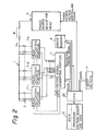
- FIG 2 is a flow chart showing one embodiment of the ink jet recording device according to the present invention, in which reference numeral 1 designates a recording head in which plural orifices are arranged in an integrated state in a predetermined direction, as shown in Figure 1, for example, in a width direction of a recording medium in full width.
- Reference numeral 3 designates heating elements each provided corresponding to each liquid path.
- Reference numeral 5 designates power source device for applying voltage to the heating elements 3 in the recording head 1, the construction of it will be explained with reference to Figure 3.
- Reference R designates line resisting value, and VH designates voltage value biased to the recording head 1.
- Reference numerals 7-1, 7-2 .... 7-k designate head actuating portions each provided to each of grouped heating elements 3, and each of actuating portions includes a shift resistor for arranging a data signal DATA of 1-line with making correspondence by 1-bit to each of the heating elements 3, a latch circuit for latching a bit data corresponding to the latch signal LAT, and a switch effecting on-off operation of the power supply, corresponding to strobe signals STRB1 - STRBk, based on the bit data.
- Reference numeral 9 designates an image for storing an image data IDATA supplied directly or via a CPU 20 from a host device H which is as an image data supplying source.
- Reference numeral 11 designates a record signal generating portion which reads out, corresponding to a timing signal T from the CPU 20, the image data developed in the image memory 9 and generating the data signal DATA, the clock signal CLK and the latch signal LAT, etc., further generating the strobe signals STRB1 - STRBk for actuating the head actuating portions 7-1 - 7-k successively.
- CPU 20 having, for example, microcomputer construction, controls each portion according to processing sequence which will be explained later in detail with reference to Figure 4.
- ROM 21 is stored a program corresponding to the processing sequence carried out by CPU 20, and a voltage adjusting data for adjusting the power source device 5 for the head.
- C is a voltage controlling signal of the power source, for example, of 2-bit binary, generated at CPU 20 for causing the power source device 5 to adjust the voltage.
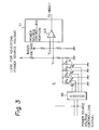
- FIG. 3 is a flow chart showing one example of the power source device 5 for the head, in which reference numeral 51 designates a power source controlling portion.
- the controlling portion 51 has a calculating amplifier 53 which receives a basic voltage signal at minus terminal and a voltage signal from a voltage adjusting line for the power source at plus terminal thereby applying voltage of predetermined value to the recording head 1.
- Plural resistors R1 - R4 of different resisting value are provided on the power source voltage adjusting line in parallell, and transistors T1 - T4 for switching are provided in series to each resistor R1 - R4, so that the resistors R1 - R4 are made to be changeable.
- a decoder 55 generates a switching signal for conducting any of the transistors T1 - T4 corresponding to the power source voltage controlling signal C of 2-bit binary which is supplied from CPU 20.
- CPU 20 adjusts voltage judging the data content developed in the memory 9.
- CPU 20 calculates the on-data number (the number of actuating bits) included in every data of predetermined amount (for example, in every total amount of data within the predetermined time period, in every one block associated with actuation by any of the head actuating portion 7-1 - 7-k, or in every data corresponding to 1-line), or calculates an average thereof; accesses to the voltage adjusting data of ROM 21 based on the result thus calculated; and determine the controlling signal C of power source voltage to supply it to the power source device 5 for the head.
- the controlling signal sent out from CPU 20 in 2-bit binary enters into the decoder 55, and any of the transistors T1 - T4 is selected to be ON corresponding to value thereof.
- the resistors R1 - R4 are switched corresponding to the above, a voltage Vin of power source voltage adjusting line will vary and the power source voltage will vary corresponding to the number of actuating bit number.
- the resistor R4 having smallest resisting value is to be selected.
- it is possible to construct the selection is made in the order of R3 to R2, R2 to R1.
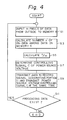
- Figure 4 is a flow chart showing one embodiment of voltage adjustment processing sequence by CPU 20.
- predetermined amount m for example, amount of 1-line
- the number of on data of the heat generating elements 3 thereamong, i.e. the number of actuating bits n is calculated in the step 3.
- value of n/m is calculated in the step S5
- 2-bit binary value of the power source voltage controlling signal C is determined with reference to the data area of ROM 21, corresponding to the value calculated.
- step S9 CPU 20 sends out the image data to the record signal generating portion 11 from the memory 9, and supplies controlling signal C to the power source device 5. If the recording is carried out in this state by actuation of the heat generating element 3, because the stabilized voltage VH is applied to the heat generating elements 3 regardless of the number actuating bits, discharging energy to be acted to the ink will be stabilized.
- step S11 existence of the image data to be recorded next is judged, and in the case there exists such data process is returned to the step S1, while if there exists no such data, process will be finished.
- the present embodiment it is possible to cause to act the stabilized discharging energy to the ink regardless of the number of actuating bits. This enables to carry out stabilized ink discharging which leads to the image recording of stabilized and high quality. Because the data is calculated with respect to the image data developed in the image memory 9 to be switched, delay for voltage compensation relative to the number of actuating bits will not occur compared with the case in which the voltage compensating circuit is added to the power source device itself.
- processing time of the above steps S1 and S3 can be shortened.
- the transistors T1 - T4 as well as the resistors R1 - R4 are provided to adjust the voltage in four stages by the controlling signal C of 2-bit binary, but it is needless to say that the number of the stages and switches are freely selected.
- the supply voltage of the power source is adjusted to make the supply voltage to the element constant, but in addition thereto, it is possible to adjust further the actuating time (on time) to the heat generating element 3 to make the actuating energy constant.
- Figure 5 is a flow chart showing another embodiment of the ink jet recording device according to the present invention, in which reference numeral 1 designates a recording head in which plural orifices are arranged in an integrated state in a predetermined direction, for example, in a width direction of a recording medium over full width.
- Reference numeral 3 designates a heating element provided to each liquid path.
- Reference numeral 5 designates power source device for applying voltage to the heating element 3 in the recording head 1.
- Reference R designates a line resisting value, and VH designates voltage value biased to the recording head 1.
- Reference numerals 7-1, 7-2 .... 7-k designates a head activating portions each provided to each of grouped heating elements 3, and each of actuating portions includes a shift resistor for arranging a data signal DATA of 1-line with making correspondence by 1-bit to each of the heating elements 3, a latch circuit for latching a bit data corresponding to the latch signal LAT, and a switch effecting on-off operation of the power supply, corresponding to strobe signals STRB1 - STRBk, based on the bit data.
- Reference numeral 9 designates an image memory for storing an image data IDATA supplied directly or via a CPU 20 from a host device H which is as an image data supplying source.
- Reference numeral 11 designates a record signal generating portion which reads out, corresponding to a timing signal T from the CPU 20, the image data developed in the image memory 9 and generating the data signal DATA, the clock signal CLK and the latch signal LAT, etc., further generating the strobe signals STRB1 -STRBk for actuating the head activating portions 7-1 -7k successively.
- Reference numeral 13 designates a pulse width controlling portion integrally provided to the record signal generating portion 11, which controlling portion 13, by controlling of CPU 20, adjusts the strobe signals STRB1 - STRBk regulating the actuation or on-time of the heat generating elements 3. This construction will be explained later with reference to Figure 6.
- CPU 20 having, for example, microcomputer construction, controls each portion according to processing sequence which will be explained later in detail with reference to Figure 8.
- ROM 21 is stored a program corresponding to the processing sequence carried out by CPU 20, and a voltage adjusting data for adjusting the power source device 5 for the head.
- CP is a pulse width controlling signal of, for example, 2-bit binary, generated by CPU 20 for causing the pulse width controlling portion to carry out the pulse width adjustment.
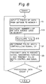
- FIG 6 is a block diagram showing one example of the pulse width controlling portion 13 in which each of references R1 - R4 shows a resistor arranged in parallell to the power source line and of different resistance value (for example, R1 > R2 > R3 >R4), and each of references T1 - T4 shows a transistor for switching arranged in series to the resistors R1 - R4 to switch and select the resistors R1 - R4.
- each of references R1 - R4 shows a resistor arranged in parallell to the power source line and of different resistance value (for example, R1 > R2 > R3 >R4)
- each of references T1 - T4 shows a transistor for switching arranged in series to the resistors R1 - R4 to switch and select the resistors R1 - R4.
- a decoder 15 generates a switching signal for conducting any of the transistors T1 - T4 corresponding to the power source voltage controlling signal CP of 2-bit binary which is supplied from CPU 20.
- Reference numeral 17 shows one-shot generator which, upon condensing of a condensor C via the selected resistor, generates a conduction regulating pulse of the heat generating elements 3 from the basic clock, based on a time period in which both ends voltage of the condensor C reaches to a predetermined value.
- CPU 20 adjusts voltage judging the data content developed in the memory 9.
- CPU 20 calculates the on-data number (the number of actuating bits) included in every data of predeter necessarilymined amount (for example, in every total amount of data with the predetermined time period, in every one block associated with actuation by any of the head actuating portion 7-1 - 7-k, or in every data corresponding to 1-line), or calculates an average thereof; accesses to the voltage adjusting data of ROM 21 based on the result thus calculated; and determine the controlling signal CP of power source voltage to supply it to the power source device 5 for the head.
- the controlling signal sent out from CPU 20 in 2-bit binary enters into the decoder 55, and any of transistors T1 - T4 is selected to be corresponding to value thereof. If the resistors R1 - R4 are switched corresponding to the above a voltage Vin of power source voltage adjusting line will vary and the power source voltage will vary correponding to the number of actuating bit number.
- the resistor enabling to obtain the conduction time regulating pulse of small pulse width T (superposed to the strobe signals STRB1 - STRBk) will be selected, and the resistor enabling to obtain the larger or wider pulse width as the number of actuating bit becomes larger will be selected.
- Figure 8 is a flow chart showing one embodiment of voltage adjustment processing sequence by CPU 20.
- m for exmaple, amount of 1-line
- the number of on data of the heat generating elements 3 thereamong, i.e. the number of actuating bits n is calculated in the step S3.
- value of n/m is calculated in the step S5, and 2-bit binary value of the power source voltage controlling signal CP is determined with reference to the data area of ROM 21, corresponding to the value calculated.
- step S9 CPU 20 sends out the image data to the record signal generating portion 11 from the memory 9, and supplies controlling signal CP to the power source device 5. If the recording is carried out in this state by actuation of the heat generating element 3, because the stabilized voltage VH is applied to the heat generating element 3 regardless of the number of actuating bit, discharging energy to be acted to the ink will be stabilized.
- step S11 existence of the image data to be recorded next is judged, and in the case there exists such data process is returned to the step S1, while if these exists no such data, process will be finished.
- the present embodiment it is possible to cause to act the stabilized discharging energy to the ink regardless of the number of actuating bits. This enables to carry out stabilized ink discharging which leads to the image recording of stabilized and of high quality. Because the recording on data is calculated with respect to the image data developed in the image memory 9 to be switched delay for voltage compensation relative to the number of actuating bits will not occur compared with the case in which the voltage compensating circuit is added to the power source device itself.
- processing time of the above steps S1 and S3 can be shortened.
- the transistors T1 - T4 as well as the resistors R1 - R4 are provided to adjust the voltage in four stages by the controlling signal CP of 2-bit binary, but it is needless to say that the number of the stage and switches are freely selected.
- the stabilized actuating energy is supplied to discharge energy generating mean regardless of the number of actuating bits, the stabilized discharging energy is acted onto the ink, which enables to carry out the image recording of high quality on account of the stabilized ink discharging condition.
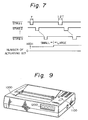
- Figure 9 is a typical perspective view showing an ink jet device of the present invention, in which reference numeral 1000 shows a body of the device, numeral 1100 shows a power source switch, and numeral 1200 shows an operating panel.
- the device is not limited to the line printer type having the recording head 1 of so-called full line type in which the discharging openings are arranged corresponding to the width of the recording medium, but the present invention can be applied effectively and easily to the type in which plural heat generating elements are actuated by the common electrode.
- the direction into which the ink is supplied to the heat generating portion of the heat generating element within the liquid path can be selected substantially same as or different from (for example, orthogonal to each other) the direction into which the ink is discharged from the discharging opening.
Abstract
Description
- The present invention relates to an ink jet recording device, in particular to the ink jet recording device in which a heating element having a heat generator and an electrode connected thereto are provided in liquid path as discharge energy generating means, and plural discharging openings communicated to the liquid path are provided.
- Because of low noise upon recording, easiness for coloring, and the character of recording to a normal sheet being possible, an ink jet recording method has been recently taken notice greatly.
- Among those methods, the ink jet recording method in which power is supplied to the heating elements provided in a fine path communicated to the discharging opening for discharging the ink therefrom to thereby generate heat, and utilizing sudden volume change upon foaming generated by heating of the ink around the heating element, in other words, the ink jet recording device utilizing thermal energy, has been taken notice because the device can be made compact and plural discharging openings can be arranged in high density.
- In such type ink jet recording device utilizing thermal energy, in the case where the recording head is constructed by arranging plural orifices in integrated state in a predetermined direction, for example, in the case of so-called full-line type recording head in which discharging openings are arranged over full width in a width direction of a recording medium, voltage is supplied to all heating elements or to every group of the predetermined number of the heating elements to actuate them.
- However, there is inevitably existed wiring resistance because of wiring lines between the recording head and the power source, actuating energy for the heating element is subject to variation resulting from amount (largeness or smallness) of the number of dots to be recorded in one time. In detail, when the number of dots is small, because of smallness of the number of the heat generating elements associated with actuation electric current flown in the lines is small and voltage decrease is small, but the electric current is large when the number of dots is large, and accordingly the voltage decrease is large.
- Difference of voltage biased to the heating element due to amount of the number of the heating elements associated with actuation leads to variation of discharging energy acting on the ink, so that recording quality may vary corresponding to the number of dots to be recorded in one time.
- It is an object of the present invention to provide the ink jet recording device in which stabilized actuating energy is supplied to the heating element regardless of the numbers of dots to be recorded in one time to act stabilized discharging energy onto the ink, thereby improving the recording quality of the ink jet recording device.
- It is another object of the present invention to provide an ink jet recording device comprising, plural energy generating means for generating energy used for discharging an ink; detecting means for detecting the number of said energy generating means actuated at the same time; adjusting means for adjusting a voltage value of the actuating pulse applied, corresponding to a result detected by said detecting means, to said energy generating means.
- It is still another object of the present invention to provide an ink jet recording device comprising, plural energy generating means for generating energy used for discharging an ink; detecting means for detecting the number of said energy generating means actuated at the same time; adjusting means for adjusting an actuating time of an actuating pulse applied to said energy generating means corresponding to a result detected by said detecting means.
-
- Figure 1 is a typical perspective view of one embodiment of the recording head used in the ink jet recording device according to the present invention.
- Figure 2 is a flow chart showing one embodiment of the ink jet recording device according to the present invention.
- Figure 3 is a block diagram showing one example of a power source device for the head in Figure 2.
- Figure 4 is a flow chart showing a processing sequence of voltage adjustment in the embodiment of Figure 2.
- Figure 5 is a block diagram showing another embodiment of the ink jet recording device according to the present invention.
- Figure 6 is a block diagram showing one example of a pulse width controlling portion in Figure 5.
- Figure 7 is a wave configuration diagram for explaining a modified embodiment of a translating time relative to the heat generating element.
- Figure 8 is a flow chart showing one example of processing sequence of pulse width adjustment in the embodiment of Figure 5.
- Figure 9 is a typical perspective view showing the ink jet recording device according to the present invention.
- The present invention is featured by adjusting the voltage value or actuating time of the actuating pulse, corresponding to the number of energy generating means actuated at the same time, to maintain the ink discharging property to be stable.
- In a preferred embodiment of the present invention, voltage adjusting means, corresponding to the number of discharging energy generating means, supplies high voltage when said number is large, while supplies low voltage when said number is small, for example.
- In another preferred embodiment of the present invention, actuation time adjusting means actuates discharge energy generating means for a long actuating time when said number is large, while short actuating time when said number is small.
- By constructions as above, stabilized actuating energy can be supplied to discharge energy generating means with cancelling influence resulted from variation of the voltage decrease due to the wire resistance corresponding to said number.
- Various embodiments according to the present invention will be explained hereinafter with reference to drawings. However, it is noted that the present invention should not be limited to the embodiments disclosed, but various modification can be made within the scope of the present invention.
- Figure 1 is a typical perspective view showing one example of a recording head used in an ink jet recording device of the present invention. In Figure 1,
reference numeral 101 designates a discharging element having liquid path in which heat generating element for generating heat energy used for ink discharging or the like are arranged as heat generating means in parallel in an integrated state, and a common chamber for storing the ink supplied to each liquid path and each ofdischarge openings 110 formed open to a front portion of each liquid path, thereby discharging the ink from thedischarging openings 110 to form recording droplets. -
Reference numeral 103 designates a base plate for fixing adischarging element 101 with an adhesive etc., whichplate 103 has an opening 102a causing thedischarging openings 110 to oppose directly to the recording medium.Reference numerals numeral 115 shows a connecting member of elbow configuration for introducing the ink into a common chamber in the discharging element,numeral 117 shows a filter unit disposed on the ink supplying path from the ink tank which is as ink supplying source, andnumeral 116 shows a supplying tube connecting the connectingmember 115 and thefilter unit 117. - Figure 2 is a flow chart showing one embodiment of the ink jet recording device according to the present invention, in which
reference numeral 1 designates a recording head in which plural orifices are arranged in an integrated state in a predetermined direction, as shown in Figure 1, for example, in a width direction of a recording medium in full width.Reference numeral 3 designates heating elements each provided corresponding to each liquid path.Reference numeral 5 designates power source device for applying voltage to theheating elements 3 in therecording head 1, the construction of it will be explained with reference to Figure 3. Reference R designates line resisting value, and VH designates voltage value biased to therecording head 1. - Reference numerals 7-1, 7-2 .... 7-k designate head actuating portions each provided to each of grouped
heating elements 3, and each of actuating portions includes a shift resistor for arranging a data signal DATA of 1-line with making correspondence by 1-bit to each of theheating elements 3, a latch circuit for latching a bit data corresponding to the latch signal LAT, and a switch effecting on-off operation of the power supply, corresponding to strobe signals STRB1 - STRBk, based on the bit data.Reference numeral 9 designates an image for storing an image data IDATA supplied directly or via aCPU 20 from a host device H which is as an image data supplying source.Reference numeral 11 designates a record signal generating portion which reads out, corresponding to a timing signal T from theCPU 20, the image data developed in theimage memory 9 and generating the data signal DATA, the clock signal CLK and the latch signal LAT, etc., further generating the strobe signals STRB1 - STRBk for actuating the head actuating portions 7-1 - 7-k successively. -
CPU 20, having, for example, microcomputer construction, controls each portion according to processing sequence which will be explained later in detail with reference to Figure 4.ROM 21 is stored a program corresponding to the processing sequence carried out byCPU 20, and a voltage adjusting data for adjusting thepower source device 5 for the head. C is a voltage controlling signal of the power source, for example, of 2-bit binary, generated atCPU 20 for causing thepower source device 5 to adjust the voltage. - Figure 3 is a flow chart showing one example of the
power source device 5 for the head, in whichreference numeral 51 designates a power source controlling portion. The controllingportion 51 has a calculatingamplifier 53 which receives a basic voltage signal at minus terminal and a voltage signal from a voltage adjusting line for the power source at plus terminal thereby applying voltage of predetermined value to therecording head 1. Plural resistors R1 - R4 of different resisting value (for exmaple, R1 > R2 >R3> R4) are provided on the power source voltage adjusting line in paralell, and transistors T1 - T4 for switching are provided in series to each resistor R1 - R4, so that the resistors R1 - R4 are made to be changeable. - A
decoder 55 generates a switching signal for conducting any of the transistors T1 - T4 corresponding to the power source voltage controlling signal C of 2-bit binary which is supplied fromCPU 20. - In such construction,
CPU 20 adjusts voltage judging the data content developed in thememory 9. In detail,CPU 20 calculates the on-data number (the number of actuating bits) included in every data of predetermined amount (for example, in every total amount of data within the predetermined time period, in every one block associated with actuation by any of the head actuating portion 7-1 - 7-k, or in every data corresponding to 1-line), or calculates an average thereof; accesses to the voltage adjusting data ofROM 21 based on the result thus calculated; and determine the controlling signal C of power source voltage to supply it to thepower source device 5 for the head. - In this way, the controlling signal sent out from
CPU 20 in 2-bit binary enters into thedecoder 55, and any of the transistors T1 - T4 is selected to be ON corresponding to value thereof. If the resistors R1 - R4 are switched corresponding to the above, a voltage Vin of power source voltage adjusting line will vary and the power source voltage will vary corresponding to the number of actuating bit number. As a result, it becomes possible to send the stabilized voltage VH to therecording head 1 regardless of the number of actuating bits. For example, when the number of actuating bits is large, because voltage decrease due to wiring resistance is remarkable, the resistor R4 having smallest resisting value is to be selected. As the number of actuating bits become smaller, it is possible to construct the selection is made in the order of R3 to R2, R2 to R1. - Figure 4 is a flow chart showing one embodiment of voltage adjustment processing sequence by
CPU 20. In the first, when predetermined amount m (for example, amount of 1-line) of image data is inputted into thememory 9 from the host device H outside in the step S1, the number of on data of theheat generating elements 3 thereamong, i.e. the number of actuating bits n is calculated in thestep 3. Then, value of n/m is calculated in the step S5, and 2-bit binary value of the power source voltage controlling signal C is determined with reference to the data area ofROM 21, corresponding to the value calculated. - In the step S9,
CPU 20 sends out the image data to the recordsignal generating portion 11 from thememory 9, and supplies controlling signal C to thepower source device 5. If the recording is carried out in this state by actuation of the heat generatingelement 3, because the stabilized voltage VH is applied to theheat generating elements 3 regardless of the number actuating bits, discharging energy to be acted to the ink will be stabilized. - Then, in the step S11, existence of the image data to be recorded next is judged, and in the case there exists such data process is returned to the step S1, while if there exists no such data, process will be finished.
- In this way, according to the present embodiment, it is possible to cause to act the stabilized discharging energy to the ink regardless of the number of actuating bits. This enables to carry out stabilized ink discharging which leads to the image recording of stabilized and high quality. Because the data is calculated with respect to the image data developed in the
image memory 9 to be switched, delay for voltage compensation relative to the number of actuating bits will not occur compared with the case in which the voltage compensating circuit is added to the power source device itself. - If the construction is made so that the number of actuating bits is calculated in a translating process of the image data IDATA to the
memory 9 by a counter or the like, processing time of the above steps S1 and S3 can be shortened. - In the above embodiment, the transistors T1 - T4 as well as the resistors R1 - R4 are provided to adjust the voltage in four stages by the controlling signal C of 2-bit binary, but it is needless to say that the number of the stages and switches are freely selected.
- Additionally, in the above embodiment only the supply voltage of the power source is adjusted to make the supply voltage to the element constant, but in addition thereto, it is possible to adjust further the actuating time (on time) to the
heat generating element 3 to make the actuating energy constant. - Figure 5 is a flow chart showing another embodiment of the ink jet recording device according to the present invention, in which
reference numeral 1 designates a recording head in which plural orifices are arranged in an integrated state in a predetermined direction, for example, in a width direction of a recording medium over full width.Reference numeral 3 designates a heating element provided to each liquid path.Reference numeral 5 designates power source device for applying voltage to theheating element 3 in therecording head 1. Reference R designates a line resisting value, and VH designates voltage value biased to therecording head 1. - Reference numerals 7-1, 7-2 .... 7-k designates a head activating portions each provided to each of grouped
heating elements 3, and each of actuating portions includes a shift resistor for arranging a data signal DATA of 1-line with making correspondence by 1-bit to each of theheating elements 3, a latch circuit for latching a bit data corresponding to the latch signal LAT, and a switch effecting on-off operation of the power supply, corresponding to strobe signals STRB1 - STRBk, based on the bit data.Reference numeral 9 designates an image memory for storing an image data IDATA supplied directly or via aCPU 20 from a host device H which is as an image data supplying source.Reference numeral 11 designates a record signal generating portion which reads out, corresponding to a timing signal T from theCPU 20, the image data developed in theimage memory 9 and generating the data signal DATA, the clock signal CLK and the latch signal LAT, etc., further generating the strobe signals STRB1 -STRBk for actuating the head activating portions 7-1 -7k successively. -
Reference numeral 13 designates a pulse width controlling portion integrally provided to the recordsignal generating portion 11, which controllingportion 13, by controlling ofCPU 20, adjusts the strobe signals STRB1 - STRBk regulating the actuation or on-time of theheat generating elements 3. This construction will be explained later with reference to Figure 6. -
CPU 20, having, for example, microcomputer construction, controls each portion according to processing sequence which will be explained later in detail with reference to Figure 8.ROM 21 is stored a program corresponding to the processing sequence carried out byCPU 20, and a voltage adjusting data for adjusting thepower source device 5 for the head. CP is a pulse width controlling signal of, for example, 2-bit binary, generated byCPU 20 for causing the pulse width controlling portion to carry out the pulse width adjustment. - Figure 6 is a block diagram showing one example of the pulse
width controlling portion 13 in which each of references R1 - R4 shows a resistor arranged in paralell to the power source line and of different resistance value (for example, R1 > R2 > R3 >R4), and each of references T1 - T4 shows a transistor for switching arranged in series to the resistors R1 - R4 to switch and select the resistors R1 - R4. - A
decoder 15 generates a switching signal for conducting any of the transistors T1 - T4 corresponding to the power source voltage controlling signal CP of 2-bit binary which is supplied fromCPU 20. -
Reference numeral 17 shows one-shot generator which, upon condensing of a condensor C via the selected resistor, generates a conduction regulating pulse of theheat generating elements 3 from the basic clock, based on a time period in which both ends voltage of the condensor C reaches to a predetermined value. - In such construction,
CPU 20 adjusts voltage judging the data content developed in thememory 9. In detial,CPU 20 calculates the on-data number (the number of actuating bits) included in every data of predetermined amount (for example, in every total amount of data with the predetermined time period, in every one block associated with actuation by any of the head actuating portion 7-1 - 7-k, or in every data corresponding to 1-line), or calculates an average thereof; accesses to the voltage adjusting data ofROM 21 based on the result thus calculated; and determine the controlling signal CP of power source voltage to supply it to thepower source device 5 for the head. - In this way, the controlling signal sent out from
CPU 20 in 2-bit binary enters into thedecoder 55, and any of transistors T1 - T4 is selected to be corresponding to value thereof. If the resistors R1 - R4 are switched corresponding to the above a voltage Vin of power source voltage adjusting line will vary and the power source voltage will vary correponding to the number of actuating bit number. - For example, in a case the number of actuating bit is small, as shown in Figure 7, since the voltage decrease due to the wire resistance is small, the resistor enabling to obtain the conduction time regulating pulse of small pulse width T (superposed to the strobe signals STRB1 - STRBk) will be selected, and the resistor enabling to obtain the larger or wider pulse width as the number of actuating bit becomes larger will be selected.
- By adjusting the conduction time in this way, because the variation of voltage decrease due to the wire resistor R corresponding largeness or smallness of the number of actuating bit can be cancelled, it becomes possible to supply the stabilized actuating energy to the
heating elements 3. - Figure 8 is a flow chart showing one embodiment of voltage adjustment processing sequence by
CPU 20. In the first, when predetermined amount m (for exmaple, amount of 1-line) of image data is inputted into thememory 9 from the host device H outside in the step S1, the number of on data of theheat generating elements 3 thereamong, i.e. the number of actuating bits n is calculated in the step S3. Then, value of n/m is calculated in the step S5, and 2-bit binary value of the power source voltage controlling signal CP is determined with reference to the data area ofROM 21, corresponding to the value calculated. - In the step S9,
CPU 20 sends out the image data to the recordsignal generating portion 11 from thememory 9, and supplies controlling signal CP to thepower source device 5. If the recording is carried out in this state by actuation of theheat generating element 3, because the stabilized voltage VH is applied to theheat generating element 3 regardless of the number of actuating bit, discharging energy to be acted to the ink will be stabilized. - Then, in the step S11, existence of the image data to be recorded next is judged, and in the case there exists such data process is returned to the step S1, while if these exists no such data, process will be finished.
- In this way, according to the present embodiment, it is possible to cause to act the stabilized discharging energy to the ink regardless of the number of actuating bits. This enables to carry out stabilized ink discharging which leads to the image recording of stabilized and of high quality. Because the recording on data is calculated with respect to the image data developed in the
image memory 9 to be switched delay for voltage compensation relative to the number of actuating bits will not occur compared with the case in which the voltage compensating circuit is added to the power source device itself. - If the construction is made so that the number of actuating bits is calculated in a translating process of the image data IDATA to the
memory 9 by a counter or the like, processing time of the above steps S1 and S3 can be shortened. - In the above embodiment, the transistors T1 - T4 as well as the resistors R1 - R4 are provided to adjust the voltage in four stages by the controlling signal CP of 2-bit binary, but it is needless to say that the number of the stage and switches are freely selected.
- Additionally, in the above embodiment only the conduction time of the
heating elements 3 is adjusted, but in addition thereto, it is possible to adjust the supplying voltage of the power device to make actuating energy constant. - As mentioned heretofore, according to the present invention, because the stabilized actuating energy is supplied to discharge energy generating mean regardless of the number of actuating bits, the stabilized discharging energy is acted onto the ink, which enables to carry out the image recording of high quality on account of the stabilized ink discharging condition.
- Figure 9 is a typical perspective view showing an ink jet device of the present invention, in which reference numeral 1000 shows a body of the device, numeral 1100 shows a power source switch, and numeral 1200 shows an operating panel.
- It is noted that the device is not limited to the line printer type having the
recording head 1 of so-called full line type in which the discharging openings are arranged corresponding to the width of the recording medium, but the present invention can be applied effectively and easily to the type in which plural heat generating elements are actuated by the common electrode. - Additionally, in the ink jet head used in the present invention, the direction into which the ink is supplied to the heat generating portion of the heat generating element within the liquid path can be selected substantially same as or different from (for example, orthogonal to each other) the direction into which the ink is discharged from the discharging opening.
Claims (16)
plural energy generating means for generating energy used for discharging an ink;
detecting means for detecting the number of said energy generating means actuated at the same time;
adjusting means for adjusting a voltage value of the actuating pulse applied, corresponding to a result detected by said detecting means, to said energy generating means.
plural energy generating means for generating energy used for discharging an ink;
detecting means for detecting the number of said energy generating means actuated at the same time;
adjusting means for adjusting an actuating time of an actuating pulse applied to said energy generating means corresponding to a result detected by said detecting means.
Applications Claiming Priority (4)
| Application Number | Priority Date | Filing Date | Title |
|---|---|---|---|
| JP29779587 | 1987-11-27 | ||
| JP29779487 | 1987-11-27 | ||
| JP297794/87 | 1987-11-27 | ||
| JP297795/87 | 1987-11-27 |
Publications (3)
| Publication Number | Publication Date |
|---|---|
| EP0318328A2 true EP0318328A2 (en) | 1989-05-31 |
| EP0318328A3 EP0318328A3 (en) | 1990-01-10 |
| EP0318328B1 EP0318328B1 (en) | 1993-10-27 |
Family
ID=26561243
Family Applications (1)
| Application Number | Title | Priority Date | Filing Date |
|---|---|---|---|
| EP88311236A Expired - Lifetime EP0318328B1 (en) | 1987-11-27 | 1988-11-28 | Ink jet recording device |
Country Status (3)
| Country | Link |
|---|---|
| US (1) | US5017948A (en) |
| EP (1) | EP0318328B1 (en) |
| DE (1) | DE3885238T2 (en) |
Cited By (22)
| Publication number | Priority date | Publication date | Assignee | Title |
|---|---|---|---|---|
| EP0405574A2 (en) * | 1989-06-30 | 1991-01-02 | Canon Kabushiki Kaisha | Recording head |
| EP0440500A1 (en) * | 1990-02-02 | 1991-08-07 | Canon Kabushiki Kaisha | Ink jet recording head and ink jet recorder incorporating that recording head |
| EP0440490A1 (en) * | 1990-02-02 | 1991-08-07 | Canon Kabushiki Kaisha | Recording method and apparatus |
| EP0440492A2 (en) * | 1990-02-02 | 1991-08-07 | Canon Kabushiki Kaisha | Recording head and a recording device utilizing the recording head |
| DE4003595A1 (en) * | 1990-02-02 | 1991-08-08 | Siemens Ag | Thermal printing system - has heating element period determined by load and internal resistance of battery |
| EP0445916A1 (en) * | 1990-02-02 | 1991-09-11 | Canon Kabushiki Kaisha | Recording head and recording apparatus using same |
| EP0461938A2 (en) * | 1990-06-15 | 1991-12-18 | Canon Kabushiki Kaisha | Ink jet recording method and ink jet recording apparatus using same |
| EP0461940A2 (en) * | 1990-06-15 | 1991-12-18 | Canon Kabushiki Kaisha | Ink jet recording apparatus and driving method therefor |
| US5214450A (en) * | 1990-06-15 | 1993-05-25 | Canon Kabushiki Kaisha | Thermal ink jet recording apparatus using a grouped transducer drive |
| EP0674994A2 (en) * | 1994-03-31 | 1995-10-04 | Xerox Corporation | Power control system for a printer |
| US5485179A (en) * | 1989-09-18 | 1996-01-16 | Canon Kabushiki Kaisha | Ink-jet recording apparatus and temperature control method therefor |
| EP0703079A2 (en) * | 1994-09-23 | 1996-03-27 | Hewlett-Packard Company | Reducing energy variations in thermal ink jet printheads |
| EP0698491A3 (en) * | 1994-08-24 | 1996-06-26 | Canon Kk | Image recording method and apparatus |
| WO1996032271A1 (en) * | 1995-04-12 | 1996-10-17 | Eastman Kodak Company | Heater power compensation for printing load in thermal printing systems |
| WO1996032272A1 (en) * | 1995-04-12 | 1996-10-17 | Eastman Kodak Company | Page image and fault tolerance control apparatus for printing systems |
| US5796418A (en) * | 1995-04-12 | 1998-08-18 | Eastman Kodak Company | Page image and fault tolerance control apparatus for printing systems |
| US5841449A (en) * | 1995-04-12 | 1998-11-24 | Eastman Kodak Company | Heater power compensation for printing load in thermal printing systems |
| US6116709A (en) * | 1991-08-01 | 2000-09-12 | Canon Kabushiki Kaisha | Ink jet recording apparatus with temperature calculation based on prestored temperature data |
| EP1004442A3 (en) * | 1998-10-31 | 2001-08-01 | Hewlett-Packard Company, A Delaware Corporation | Varying the operating energy applied to an inkjet print cartridge based upon the printmode being used |
| EP1125742A1 (en) * | 2000-02-15 | 2001-08-22 | Canon Kabushiki Kaisha | Printing apparatus and method of controlling power supply thereof |
| WO2005032824A1 (en) * | 2003-09-24 | 2005-04-14 | Hewlett-Packard Development Company, L.P. | Variable drive for printhead |
| EP1946933A3 (en) * | 2007-01-17 | 2009-07-01 | Brother Kogyo Kabushiki Kaisha | Inkjet recording apparatus |
Families Citing this family (6)
| Publication number | Priority date | Publication date | Assignee | Title |
|---|---|---|---|---|
| US6116710A (en) * | 1991-01-18 | 2000-09-12 | Canon Kabushiki Kaisha | Ink jet recording method and apparatus using thermal energy |
| JPH068474A (en) * | 1992-06-26 | 1994-01-18 | Canon Inc | Ink jet recording device |
| JPH07251506A (en) * | 1994-02-18 | 1995-10-03 | Xerox Corp | Heating element control system |
| US5790144A (en) * | 1996-09-25 | 1998-08-04 | Lexmark International, Inc. | Method of controlling an operating temperature of a printhead in an ink jet cartridge assembly |
| US6116717A (en) * | 1998-09-15 | 2000-09-12 | Lexmark International, Inc. | Method and apparatus for customized control of a print cartridge |
| US6652058B2 (en) * | 2001-02-22 | 2003-11-25 | Canon Kabushiki Kaisha | Recording apparatus and recording control method, and ink jet recording method and apparatus |
Citations (7)
| Publication number | Priority date | Publication date | Assignee | Title |
|---|---|---|---|---|
| US4095232A (en) * | 1977-07-18 | 1978-06-13 | The Mead Corporation | Apparatus for producing multiple uniform fluid filaments and drops |
| US4241406A (en) * | 1978-12-21 | 1980-12-23 | International Business Machines Corporation | System and method for analyzing operation of an ink jet head |
| US4277790A (en) * | 1979-12-26 | 1981-07-07 | International Business Machines Corporation | Field replaceable modules for ink jet head assembly |
| US4303927A (en) * | 1977-03-23 | 1981-12-01 | International Business Machines Corporation | Apparatus for exciting an array of ink jet nozzles and method of forming |
| US4510505A (en) * | 1981-07-03 | 1985-04-09 | Canon Kabushiki Kaisha | Thermal printer |
| EP0202922A2 (en) * | 1985-05-24 | 1986-11-26 | Ncr Canada Ltd - Ncr Canada Ltee | Thermal printing system |
| US4684957A (en) * | 1985-07-16 | 1987-08-04 | Matsushita Electric Industrial Co., Ltd. | Method for operation of an ink jet printing head |
Family Cites Families (7)
| Publication number | Priority date | Publication date | Assignee | Title |
|---|---|---|---|---|
| US4345262A (en) * | 1979-02-19 | 1982-08-17 | Canon Kabushiki Kaisha | Ink jet recording method |
| US4463359A (en) * | 1979-04-02 | 1984-07-31 | Canon Kabushiki Kaisha | Droplet generating method and apparatus thereof |
| US4520373A (en) * | 1979-04-02 | 1985-05-28 | Canon Kabushiki Kaisha | Droplet generating method and apparatus therefor |
| US4558332A (en) * | 1982-04-02 | 1985-12-10 | Canon Kabushiki Kaisha | Ink jet printer |
| US4563689A (en) * | 1983-02-05 | 1986-01-07 | Konishiroku Photo Industry Co., Ltd. | Method for ink-jet recording and apparatus therefor |
| JPH062411B2 (en) * | 1983-04-22 | 1994-01-12 | キヤノン株式会社 | Liquid jet recording device |
| JPH0729418B2 (en) * | 1986-02-28 | 1995-04-05 | キヤノン株式会社 | Liquid jet recording device |
-
1988
- 1988-11-28 DE DE88311236T patent/DE3885238T2/en not_active Expired - Lifetime
- 1988-11-28 EP EP88311236A patent/EP0318328B1/en not_active Expired - Lifetime
-
1990
- 1990-04-24 US US07/512,600 patent/US5017948A/en not_active Expired - Lifetime
Patent Citations (7)
| Publication number | Priority date | Publication date | Assignee | Title |
|---|---|---|---|---|
| US4303927A (en) * | 1977-03-23 | 1981-12-01 | International Business Machines Corporation | Apparatus for exciting an array of ink jet nozzles and method of forming |
| US4095232A (en) * | 1977-07-18 | 1978-06-13 | The Mead Corporation | Apparatus for producing multiple uniform fluid filaments and drops |
| US4241406A (en) * | 1978-12-21 | 1980-12-23 | International Business Machines Corporation | System and method for analyzing operation of an ink jet head |
| US4277790A (en) * | 1979-12-26 | 1981-07-07 | International Business Machines Corporation | Field replaceable modules for ink jet head assembly |
| US4510505A (en) * | 1981-07-03 | 1985-04-09 | Canon Kabushiki Kaisha | Thermal printer |
| EP0202922A2 (en) * | 1985-05-24 | 1986-11-26 | Ncr Canada Ltd - Ncr Canada Ltee | Thermal printing system |
| US4684957A (en) * | 1985-07-16 | 1987-08-04 | Matsushita Electric Industrial Co., Ltd. | Method for operation of an ink jet printing head |
Cited By (46)
| Publication number | Priority date | Publication date | Assignee | Title |
|---|---|---|---|---|
| EP0405574A3 (en) * | 1989-06-30 | 1991-01-23 | Canon Kabushiki Kaisha | Recording head and recording apparatus |
| EP0405574A2 (en) * | 1989-06-30 | 1991-01-02 | Canon Kabushiki Kaisha | Recording head |
| US5485179A (en) * | 1989-09-18 | 1996-01-16 | Canon Kabushiki Kaisha | Ink-jet recording apparatus and temperature control method therefor |
| US6067100A (en) * | 1989-09-18 | 2000-05-23 | Canon Kabushiki Kaisha | Ink-jet recording apparatus and temperature control method therefor |
| US6102514A (en) * | 1989-09-18 | 2000-08-15 | Canon Kabushiki Kaisha | Ink-jet recording apparatus and temperature control method therefor |
| US5157411A (en) * | 1990-02-02 | 1992-10-20 | Canon Kabushiki Kaisha | Recording head and a recording device utilizing the recording head |
| US5357268A (en) * | 1990-02-02 | 1994-10-18 | Canon Kabushiki Kaisha | Ink jet recording head in which the ejection elements are driven in blocks |
| US5975667A (en) * | 1990-02-02 | 1999-11-02 | Canon Kabushiki Kaisha | Ink jet recording apparatus and method utilizing two-pulse driving |
| EP0440500A1 (en) * | 1990-02-02 | 1991-08-07 | Canon Kabushiki Kaisha | Ink jet recording head and ink jet recorder incorporating that recording head |
| EP0440492A3 (en) * | 1990-02-02 | 1991-12-27 | Canon Kabushiki Kaisha | Recording head and a recording device utilizing the recording head |
| EP0440490A1 (en) * | 1990-02-02 | 1991-08-07 | Canon Kabushiki Kaisha | Recording method and apparatus |
| EP0445916A1 (en) * | 1990-02-02 | 1991-09-11 | Canon Kabushiki Kaisha | Recording head and recording apparatus using same |
| EP0440492A2 (en) * | 1990-02-02 | 1991-08-07 | Canon Kabushiki Kaisha | Recording head and a recording device utilizing the recording head |
| US5173717A (en) * | 1990-02-02 | 1992-12-22 | Canon Kabushiki Kaisha | Ink jet recording head in which the ejection elements are driven in blocks |
| DE4003595A1 (en) * | 1990-02-02 | 1991-08-08 | Siemens Ag | Thermal printing system - has heating element period determined by load and internal resistance of battery |
| US5305024A (en) * | 1990-02-02 | 1994-04-19 | Canon Kabushiki Kaisha | Recording head and recording apparatus using same |
| US5353051A (en) * | 1990-02-02 | 1994-10-04 | Canon Kabushiki Kaisha | Recording apparatus having a plurality of recording elements divided into blocks |
| EP0461940A3 (en) * | 1990-06-15 | 1992-08-05 | Canon Kabushiki Kaisha | Ink jet recording apparatus and driving method therefor |
| US6439692B1 (en) | 1990-06-15 | 2002-08-27 | Canon Kabushiki Kaisha | Ink jet recording apparatus and driving method thereof using a flow resistance element to promote collapse of a generated bubble |
| US5214450A (en) * | 1990-06-15 | 1993-05-25 | Canon Kabushiki Kaisha | Thermal ink jet recording apparatus using a grouped transducer drive |
| US6341849B1 (en) * | 1990-06-15 | 2002-01-29 | Canon Kabushiki Kaisha | Ink jet recording apparatus having flow resistance elements and driving method therefor |
| US6244693B1 (en) | 1990-06-15 | 2001-06-12 | Canon Kabushiki Kaisha | Ink jet recording apparatus having a flow resistance element and driving method |
| EP0770485A3 (en) * | 1990-06-15 | 1997-06-11 | Canon Kk | |
| EP0461938A3 (en) * | 1990-06-15 | 1992-04-08 | Canon Kabushiki Kaisha | Ink jet recording method and ink jet recording apparatus using same |
| EP0461940A2 (en) * | 1990-06-15 | 1991-12-18 | Canon Kabushiki Kaisha | Ink jet recording apparatus and driving method therefor |
| EP0461938A2 (en) * | 1990-06-15 | 1991-12-18 | Canon Kabushiki Kaisha | Ink jet recording method and ink jet recording apparatus using same |
| US6116709A (en) * | 1991-08-01 | 2000-09-12 | Canon Kabushiki Kaisha | Ink jet recording apparatus with temperature calculation based on prestored temperature data |
| EP0674994A2 (en) * | 1994-03-31 | 1995-10-04 | Xerox Corporation | Power control system for a printer |
| EP0674994A3 (en) * | 1994-03-31 | 1996-05-15 | Xerox Corp | Power control system for a printer. |
| EP0698491A3 (en) * | 1994-08-24 | 1996-06-26 | Canon Kk | Image recording method and apparatus |
| US6155663A (en) * | 1994-08-24 | 2000-12-05 | Canon Kabushiki Kaisha | Image recording method and apparatus |
| EP0703079A2 (en) * | 1994-09-23 | 1996-03-27 | Hewlett-Packard Company | Reducing energy variations in thermal ink jet printheads |
| EP0703079A3 (en) * | 1994-09-23 | 1996-05-29 | Hewlett Packard Co | Reducing energy variations in thermal ink jet printheads |
| US5677577A (en) * | 1994-09-23 | 1997-10-14 | Hewlett-Packard Company | Reducing energy variations in thermal inkjet printers |
| WO1996032271A1 (en) * | 1995-04-12 | 1996-10-17 | Eastman Kodak Company | Heater power compensation for printing load in thermal printing systems |
| WO1996032272A1 (en) * | 1995-04-12 | 1996-10-17 | Eastman Kodak Company | Page image and fault tolerance control apparatus for printing systems |
| US5841449A (en) * | 1995-04-12 | 1998-11-24 | Eastman Kodak Company | Heater power compensation for printing load in thermal printing systems |
| US5796418A (en) * | 1995-04-12 | 1998-08-18 | Eastman Kodak Company | Page image and fault tolerance control apparatus for printing systems |
| US6334660B1 (en) | 1998-10-31 | 2002-01-01 | Hewlett-Packard Company | Varying the operating energy applied to an inkjet print cartridge based upon the operating conditions |
| EP1004442A3 (en) * | 1998-10-31 | 2001-08-01 | Hewlett-Packard Company, A Delaware Corporation | Varying the operating energy applied to an inkjet print cartridge based upon the printmode being used |
| EP1125742A1 (en) * | 2000-02-15 | 2001-08-22 | Canon Kabushiki Kaisha | Printing apparatus and method of controlling power supply thereof |
| US6663209B2 (en) | 2000-02-15 | 2003-12-16 | Canon Kabushiki Kaisha | Printing apparatus and method of controlling power supply thereof |
| WO2005032824A1 (en) * | 2003-09-24 | 2005-04-14 | Hewlett-Packard Development Company, L.P. | Variable drive for printhead |
| US7719712B2 (en) | 2003-09-24 | 2010-05-18 | Hewlett-Packard Development Company, L.P. | Variable drive for printhead |
| EP1946933A3 (en) * | 2007-01-17 | 2009-07-01 | Brother Kogyo Kabushiki Kaisha | Inkjet recording apparatus |
| US7926901B2 (en) | 2007-01-17 | 2011-04-19 | Brother Kogyo Kabushiki Kaisha | Inkjet recording apparatus |
Also Published As
| Publication number | Publication date |
|---|---|
| DE3885238D1 (en) | 1993-12-02 |
| DE3885238T2 (en) | 1994-03-03 |
| EP0318328B1 (en) | 1993-10-27 |
| EP0318328A3 (en) | 1990-01-10 |
| US5017948A (en) | 1991-05-21 |
Similar Documents
| Publication | Publication Date | Title |
|---|---|---|
| EP0318328A2 (en) | Ink jet recording device | |
| EP0571093B1 (en) | Integrated circuit printhead for an ink jet printer including an integrated identification circuit | |
| KR100244815B1 (en) | Ink jet print head identification circuit with programmed transistor array | |
| US6022094A (en) | Memory expansion circuit for ink jet print head identification circuit | |
| JP3217836B2 (en) | Energy control circuit for thermal inkjet printhead | |
| US4396923A (en) | Recording control apparatus | |
| US5635968A (en) | Thermal inkjet printer printhead with offset heater resistors | |
| US6276772B1 (en) | Ink jet printer using piezoelectric elements with improved ink droplet impinging accuracy | |
| US6932453B2 (en) | Inkjet printhead assembly having very high drop rate generation | |
| EP0607513B1 (en) | Improved power supply for individual control of power delivered to integrated drive thermal inkjet printhead heater resistors | |
| KR0138202B1 (en) | Substrate for thermal recording head ink-jet recording head using the substrate | |
| JP2607514B2 (en) | Thermal printing equipment | |
| EP0545260A2 (en) | Method and apparatus for driving a thermal head to reduce parasitic resistance effects | |
| US6860577B2 (en) | Device for preventing printer header from overheating | |
| KR101093481B1 (en) | Fluid ejection device identification | |
| AU703915B2 (en) | Thermal head apparatus | |
| US6193342B1 (en) | Ink jet printer, and ink discharge velocity adjusting method and apparatus in the same | |
| CN114083900B (en) | Printing element substrate, printhead, and printing apparatus | |
| EP0925927B1 (en) | Ink jet recording apparatus and method of driving the same | |
| US5191355A (en) | Device for adjusting the heat-generating time of a thermal printer head | |
| JPS6232860Y2 (en) | ||
| JP3180290B2 (en) | Thermal head | |
| JPH07137328A (en) | Intermediate tone recording apparatus | |
| JPH05338208A (en) | Driving method for thermal head | |
| JPH06246955A (en) | Apparatus for controlling thermal head |
Legal Events
| Date | Code | Title | Description |
|---|---|---|---|
| PUAI | Public reference made under article 153(3) epc to a published international application that has entered the european phase |
Free format text: ORIGINAL CODE: 0009012 |
|
| AK | Designated contracting states |
Kind code of ref document: A2 Designated state(s): DE FR GB IT |
|
| PUAL | Search report despatched |
Free format text: ORIGINAL CODE: 0009013 |
|
| AK | Designated contracting states |
Kind code of ref document: A3 Designated state(s): DE FR GB IT |
|
| 17P | Request for examination filed |
Effective date: 19900525 |
|
| 17Q | First examination report despatched |
Effective date: 19911030 |
|
| GRAA | (expected) grant |
Free format text: ORIGINAL CODE: 0009210 |
|
| AK | Designated contracting states |
Kind code of ref document: B1 Designated state(s): DE FR GB IT |
|
| ITTA | It: last paid annual fee | ||
| REF | Corresponds to: |
Ref document number: 3885238 Country of ref document: DE Date of ref document: 19931202 |
|
| ET | Fr: translation filed | ||
| ITF | It: translation for a ep patent filed |
Owner name: SOCIETA' ITALIANA BREVETTI S.P.A. |
|
| PLBE | No opposition filed within time limit |
Free format text: ORIGINAL CODE: 0009261 |
|
| STAA | Information on the status of an ep patent application or granted ep patent |
Free format text: STATUS: NO OPPOSITION FILED WITHIN TIME LIMIT |
|
| 26N | No opposition filed | ||
| REG | Reference to a national code |
Ref country code: GB Ref legal event code: IF02 |
|
| PGFP | Annual fee paid to national office [announced via postgrant information from national office to epo] |
Ref country code: DE Payment date: 20071130 Year of fee payment: 20 |
|
| PGFP | Annual fee paid to national office [announced via postgrant information from national office to epo] |
Ref country code: IT Payment date: 20071120 Year of fee payment: 20 |
|
| PGFP | Annual fee paid to national office [announced via postgrant information from national office to epo] |
Ref country code: FR Payment date: 20071122 Year of fee payment: 20 Ref country code: GB Payment date: 20071112 Year of fee payment: 20 |
|
| REG | Reference to a national code |
Ref country code: GB Ref legal event code: PE20 Expiry date: 20081127 |
|
| PG25 | Lapsed in a contracting state [announced via postgrant information from national office to epo] |
Ref country code: GB Free format text: LAPSE BECAUSE OF EXPIRATION OF PROTECTION Effective date: 20081127 |