EP0317267A2 - Ink jet recording apparatus and discharge recovery device used with the same - Google Patents
Ink jet recording apparatus and discharge recovery device used with the same Download PDFInfo
- Publication number
- EP0317267A2 EP0317267A2 EP88310777A EP88310777A EP0317267A2 EP 0317267 A2 EP0317267 A2 EP 0317267A2 EP 88310777 A EP88310777 A EP 88310777A EP 88310777 A EP88310777 A EP 88310777A EP 0317267 A2 EP0317267 A2 EP 0317267A2
- Authority
- EP
- European Patent Office
- Prior art keywords
- cap member
- ink
- discharge openings
- suction means
- discharge
- Prior art date
- Legal status (The legal status is an assumption and is not a legal conclusion. Google has not performed a legal analysis and makes no representation as to the accuracy of the status listed.)
- Granted
Links
- 238000011084 recovery Methods 0.000 title claims description 6
- 238000004891 communication Methods 0.000 claims abstract description 56
- 230000006854 communication Effects 0.000 claims abstract description 56
- 238000007599 discharging Methods 0.000 claims abstract description 12
- 230000001419 dependent effect Effects 0.000 claims 1
- 239000007788 liquid Substances 0.000 description 64
- 239000000976 ink Substances 0.000 description 45
- 230000000875 corresponding effect Effects 0.000 description 9
- 238000010276 construction Methods 0.000 description 3
- 238000011109 contamination Methods 0.000 description 3
- 229920005549 butyl rubber Polymers 0.000 description 1
- 230000003247 decreasing effect Effects 0.000 description 1
- 239000000428 dust Substances 0.000 description 1
- 230000000694 effects Effects 0.000 description 1
- 230000005484 gravity Effects 0.000 description 1
- 230000012447 hatching Effects 0.000 description 1
- 230000000977 initiatory effect Effects 0.000 description 1
- 239000000463 material Substances 0.000 description 1
- 238000000034 method Methods 0.000 description 1
- 238000012986 modification Methods 0.000 description 1
- 230000004048 modification Effects 0.000 description 1
- 230000002093 peripheral effect Effects 0.000 description 1
- 229920002379 silicone rubber Polymers 0.000 description 1
- 238000007711 solidification Methods 0.000 description 1
- 230000008023 solidification Effects 0.000 description 1
Images
Classifications
-
- B—PERFORMING OPERATIONS; TRANSPORTING
- B41—PRINTING; LINING MACHINES; TYPEWRITERS; STAMPS
- B41J—TYPEWRITERS; SELECTIVE PRINTING MECHANISMS, i.e. MECHANISMS PRINTING OTHERWISE THAN FROM A FORME; CORRECTION OF TYPOGRAPHICAL ERRORS
- B41J2/00—Typewriters or selective printing mechanisms characterised by the printing or marking process for which they are designed
- B41J2/005—Typewriters or selective printing mechanisms characterised by the printing or marking process for which they are designed characterised by bringing liquid or particles selectively into contact with a printing material
- B41J2/01—Ink jet
- B41J2/17—Ink jet characterised by ink handling
- B41J2/18—Ink recirculation systems
-
- B—PERFORMING OPERATIONS; TRANSPORTING
- B41—PRINTING; LINING MACHINES; TYPEWRITERS; STAMPS
- B41J—TYPEWRITERS; SELECTIVE PRINTING MECHANISMS, i.e. MECHANISMS PRINTING OTHERWISE THAN FROM A FORME; CORRECTION OF TYPOGRAPHICAL ERRORS
- B41J2/00—Typewriters or selective printing mechanisms characterised by the printing or marking process for which they are designed
- B41J2/005—Typewriters or selective printing mechanisms characterised by the printing or marking process for which they are designed characterised by bringing liquid or particles selectively into contact with a printing material
- B41J2/01—Ink jet
- B41J2/135—Nozzles
- B41J2/145—Arrangement thereof
- B41J2/155—Arrangement thereof for line printing
-
- B—PERFORMING OPERATIONS; TRANSPORTING
- B41—PRINTING; LINING MACHINES; TYPEWRITERS; STAMPS
- B41J—TYPEWRITERS; SELECTIVE PRINTING MECHANISMS, i.e. MECHANISMS PRINTING OTHERWISE THAN FROM A FORME; CORRECTION OF TYPOGRAPHICAL ERRORS
- B41J2/00—Typewriters or selective printing mechanisms characterised by the printing or marking process for which they are designed
- B41J2/005—Typewriters or selective printing mechanisms characterised by the printing or marking process for which they are designed characterised by bringing liquid or particles selectively into contact with a printing material
- B41J2/01—Ink jet
- B41J2/135—Nozzles
- B41J2/165—Preventing or detecting of nozzle clogging, e.g. cleaning, capping or moistening for nozzles
- B41J2/16517—Cleaning of print head nozzles
- B41J2/1652—Cleaning of print head nozzles by driving a fluid through the nozzles to the outside thereof, e.g. by applying pressure to the inside or vacuum at the outside of the print head
- B41J2/16532—Cleaning of print head nozzles by driving a fluid through the nozzles to the outside thereof, e.g. by applying pressure to the inside or vacuum at the outside of the print head by applying vacuum only
Definitions
- the present invention relates to an ink jet recording apparatus, and, more particularly, it relates to a discharge recovery or restoring device for an ink jet recording apparatus, which is provided with a cap capable of covering a recording liquid discharge surface to prevent the jamming of discharge openings of a recording head and to prepare initial charge or introduction of a recording liquid and of permitting suction of ink (recording liquid) and/or air.
- flying drops of recording liquid are created by discharging the recording liquid from minute or small discharge ports or openings each having a diameter of the order of about 40 - 50 ⁇ m.
- bubbles are accumulated in liquid passages into which the recording liquid is introduced, and dust sticked about and around the discharge openings and/or solidification of the recording liquid may cause non-discharge of the recording liquid (from the discharge openings) and deviation of the discharge liquid drops with respect to a recording medium.
- Such a cap member was so constructed that the recording head brought into a home position was covered by the cap member and that the recording liquid was sucked through the discharge openings arranged on the discharge face by means of an appropriate suction means communicating with the cap member.
- Fig. 1 shows an example of a cam member of the conventional discharge restoring device, such as shown in the U.K. Patent Laid-Open No. GB-2184066 A.
- This Figure shows a condition that a front plate 3 of a recording head 2 is covered by a cap member 1.
- the recording head 2 includes a plurality of discharge openings 4 arranged on the front plate 3 along an up-and-down direction, and a plurality of liquid passages 6 for communicating a common liquid chamber 5 with the corresponding discharge openings to direct the recording liquid in the liquid chamber 5 to the discharge openings 4.
- discharge energy generating means such as piezo-electrical elements, electrical-thermal converters and the like.
- a space 8 defined by the plate 3 and cover 1 is fluid-tight sealed with respect to the atmosphere by engaging an elastic seal 7 (such as a silicon rubber ring, butyl rubber ring and the like) arranged on a peripheral edge of the cap member 3 with the front plate 3.
- the cap member 1 has a communication port 9 at a lower portion of the space or cavity 8, which port 9 is communicated with an external suction pump 10.
- the communication port 9 was positioned in the lower portion of the cavity 8 of the cover member 1 not to leave the recording liquid after the liquid was drawn through the communication port, thus preventing the liquid from dropping out of the cavity, and thus preventing the contamination of the apparatus, when the cover member 1 was separated from the front plate of the recording head 2.
- a great number for example, about 1792
- the discharge openings are arranged substantially along a single line.
- An object of the present invention is to provide a restoring device and an ink jet recording apparatus having such restoring device, which can solve the above-mentioned problems, and wherein all of the liquid passages including uppermost and lowermost ones or leftmost and rightmost ones are completely filled with a recording liquid and the recording liquid is sucked through all of discharge openings, so that the effective discharge can be effected when a recording operation is started again.
- Another object of the invention is to provide a discharge restoring device for an ink jet recording apparatus, which comprises a cap for covering a plurality of discharge openings for discharging ink, and a suction means for sucking the ink and/or air from the plurality of discharge openings through the cap, and wherein a communication port communicating the suction means with the interior of the cap is provided at an upper portion of the cap.
- an ink jet recording apparatus which comprises a recording head having a plurality of discharge openings provided along an up-and-down direction for discharging ink, a cap for covering the plurality of discharge openings, a suction means for sucking the ink and/or air from the discharge openings through the cap, a shifting means for shifting the cap in a position where the cap covers the plurality of discharge openings, and a drive means for driving the suction means after the plurality of discharge openings are covered by the cap by means of the shifting means, and wherein a communication port communicating the suction means with the interior of the cap is provided at an upper portion of the cap and the ink and/or air are sucked through the communication port by the suction means.
- a further object of the present invention is to provide a discharge restoring device for an ink jet recording apparatus, which comprises a cap for covering a plurality of discharge openings for discharge ink, and at least one suction means for sucking the ink and/or air from the plurality of discharge openings through the cap, and wherein the cap has a plurality of communication ports communicating with the suction means and the ink and/or air are sucked through the communication ports.
- Still further object of the present invention is to provide an ink jet recording apparatus which comprises a recording head having a plurality of discharge openings for discharging ink, a cap for covering the plurality of discharge openings, a suction means for sucking the ink and/or air from the discharge openings through the cap, a shifting means for shifting the cap in a position where the cap covers the plurality of discharge openings, and a drive means for driving the suction means after the plurality of discharge openings are covered by the cap by means of the shifting means, and wherein the cap has a plurality of communication ports communicating with the suction means and the ink and/or air are sucked through the communication means.
- the other object of the present invention is to provide an ink jet recording apparatus which can suck or draw ink and/or air through all of discharge openings by sucking the ink and/or through a main communication port provided at an upper portion of a sealed cavity, thus filling all of liquid passages and a common chamber with the ink completely, and thereafter can empty the cavity by exhausting the ink (recording liquid) in the cavity through a secondary communication port, thereby preventing the contamination of the apparatus when a cap member is separated from a recording head of the apparatus.
- a cap member 11 is provided with a main suction port or communication port 12 communicating with an upper portion of a space or cavity 8 of the cap member, and a second suction port or communication port 13 communicating with a lower portion of the cavity 8.
- the commudnication ports 12 and 13 are communicated with a pump 14 through communication conduits or suction paths 12A and 13A, respectively, so that a recording liquid and/or air can be drawn or sucked from the cavity 8 through both of the communication ports 12 and 13.
- a diameter of the suction path 12A is larger than that of the suction path 13A.
- the suction paths i.e., communication conduits 12A and 13A are made of the same material; thus, due to the difference in diameter as stated above, channel resistance of the communication conduit 12A is smaller than that of the communication conduit 13A.
- the channel resistances of the communication conduits may be differentiated as above, for example, by changing the dimensions of the suction port and/or making walls of the conduits with different rough surfaces.
- the recording liquid is introduced in the manner shown in Fig. 1 to leave an air space or unfilled area in upper portions of the chamber 5 and cavity 8, since the air is continuously sucked through the main communication port 12 by the suction pump 14, the chamber 5, liquid passages 6 and cavity 8 are completely filled with the recording liquid as shown by a hatched portion in Fig. 2 for an extremely short time with less power, without leaving the air in the cavity as in the conventional device.
- the pump to cooperate with the second communication conduit 13A, the recording liquid in the cavity 8 is completely drawn through the second lower communication port 13, thus emptying the cavity so that the cap member 11 can be separated from the recording head 2 without contamination of the recording apparatus.
- Fig. 3 shows an ink jet recording apparatus according to the second embodiment of the present invention.
- recording head 121a, 121b, 121c and 121d can perform the recording operation while moving in a direction shown by an arrow AA, with respect to a recording medium P brought into a recording position by means of a platen roller 101 as a conveying means.
- the recording heads 121a, 121b, 121c and 121d can discharge cyan ink, magenta ink, yellow ink and black ink, respectively.
- the recording heads are mounted on a shiftable carriage 102 guided along a guide bar 103, so that the heads can be moved to perform a scanning operation.
- the carriage 102 is drive by a driving motor 104 through a belt 104A.
- Ink supply conduits 121 for supplying a predetermined inks to the corresponding recording heads are fixed to a conventional flexible cable 120 to move together with it and are connected to corresponding ink tanks (not shown).
- the recording heads 121a-121d positioned in the home position are covered by a cap member 110.
- the cap member includes cavities associated with the corresponding recording heads.
- the suction system of this embodiment is substantially the same as that of the first embodiment described above, except that a vent valve 112 is provided in the communication conduit in its half way for communicating the corresponding cavity with the atmosphere.
- the cap member 110 is shifted to cover the discharge openings of the recording heads by a shifting means 111.
- the control unit 105 switches the three-way valves 112 to connect pumps 113 to corresponding communication ports 114, then energizes the pump 113 to create the pressure difference between the cap member and the atmosphere, thus sucking the ink and/or air from the discharge openings of the recording heads 121a-121d through the communication ports 114, 115 provided on the cap member 110.
- the control unit 105 switches the three-way valves 112 to vent the cavities of the cap member 110 to the atmosphere, thus sucking the inks filling the corresponding cavities through the lower communication ports 115 to empty the cavities and introduce the air into the cavities through the valves 112.
- each of the recording heads may include the ink tank therein and may be removably mounted on the carriage individually.
- the recording apparatus includes a recording head 212 which can perform the recording operation in stationary with respect to a recording medium P, and a roller 201 for conveying the recording medium P.
- a cap 210 is so constructed as to move and cover discharge openings 212A of the recording head 212 in inoperative condition.
- the cap 210 includes communication ports 214 and 215 communicated with a suction pump 213 through corresponding communication conduits 214A and 215A, thus communicating the interior of the cap 210 with the suction pump 213.
- the communication port 215 is positioned in confronting relation to the leftmost (Fig. 4) discharge opening 212A, whereas the communication port 214 is positioned in confronting relation to the rightmost discharge openings 212A.
- the cap is communicated with the suction generating souce, at plural points, preferably, at both ends of the cap, it is possible to decrease the difference in suction forces for the respective discharge openings and to perform the effective restoring (suction) operation even in the recording head of full-line type.
- the recording heads illustrated in the above-mentioned embodiments it is preferably to adopt a method of producing images with a recording liquid that utilizes thermal energy for forming drops of the recording liquid. And, it is desirable to provide electrical-thermal converters in correspondence to the respective discharge openings to generate the thermal energy.
- Such recording head can preferably be used since it is easy to form multi-orifice construction.
- the communication ports communicating with the interior if the cap member are provided at the upper portion of the cap member, "the upper portion” is defined to be above a position respective to a center, or a center in the direction of the gravity, of an array of discharging openings in respective recording heads or more preferably above a position corresponding to the uppermost discharge opening (Fig. 2).
- the communication port communicating with the suction means is arranged at least upper portion of a sealed space defined by mounting the cap member against the discharge face of the recording head, during the restoring operation for the recording head, the air is sucked from the sealed cavity through the upper portion thereof, whereby the recording liquid can be introduced into the cavity through all of the discharge openings including the upper ones, thus completely filling the liquid chamber and all of the liquid passages with the recording liquid.
- the communication port communicating with the suction means is arranged at least upper portion of a sealed space defined by mounting the cap member against the discharge face of the recording head, during the restoring operation for the recording head, the air is sucked from the sealed cavity through the upper portion thereof, whereby the recording liquid can be introduced into the cavity through all of the discharge openings including the upper ones, thus completely filling the liquid chamber and all of the liquid passages with the recording liquid.
Abstract
Description
- The present invention relates to an ink jet recording apparatus, and, more particularly, it relates to a discharge recovery or restoring device for an ink jet recording apparatus, which is provided with a cap capable of covering a recording liquid discharge surface to prevent the jamming of discharge openings of a recording head and to prepare initial charge or introduction of a recording liquid and of permitting suction of ink (recording liquid) and/or air.
- In a recording head used with an ink jet recording apparatus, flying drops of recording liquid are created by discharging the recording liquid from minute or small discharge ports or openings each having a diameter of the order of about 40 - 50µm. However, with such construction, there is a tendency that bubbles are accumulated in liquid passages into which the recording liquid is introduced, and dust sticked about and around the discharge openings and/or solidification of the recording liquid may cause non-discharge of the recording liquid (from the discharge openings) and deviation of the discharge liquid drops with respect to a recording medium.
- For these reasons, in the past, as shown in U.S. Patent No. 4,600,931 in order to eliminate the above drawbacks and to facilitate the initial introduction of the recording liquid to the liquid passages of the recording head, for example, when the recording head is used again after it is preserved for a long time, a suction operation called as a restoring operation has been utilized by covering the recording liquid discharge face of the recording head by means of a cap member.
- Such a cap member was so constructed that the recording head brought into a home position was covered by the cap member and that the recording liquid was sucked through the discharge openings arranged on the discharge face by means of an appropriate suction means communicating with the cap member.
- Fig. 1 shows an example of a cam member of the conventional discharge restoring device, such as shown in the U.K. Patent Laid-Open No. GB-2184066 A. This Figure shows a condition that a
front plate 3 of arecording head 2 is covered by a cap member 1. Therecording head 2 includes a plurality ofdischarge openings 4 arranged on thefront plate 3 along an up-and-down direction, and a plurality ofliquid passages 6 for communicating a commonliquid chamber 5 with the corresponding discharge openings to direct the recording liquid in theliquid chamber 5 to thedischarge openings 4. When the recording operation is started, the recording liquid is discharged from thedischarge openings 4 by means of discharge energy generating means (not shown) such as piezo-electrical elements, electrical-thermal converters and the like. - When the cap member 1 is mounted on the
front plate 3 of the recording head 2 (as shown), aspace 8 defined by theplate 3 and cover 1 is fluid-tight sealed with respect to the atmosphere by engaging an elastic seal 7 (such as a silicon rubber ring, butyl rubber ring and the like) arranged on a peripheral edge of thecap member 3 with thefront plate 3. The cap member 1 has a communication port 9 at a lower portion of the space orcavity 8, which port 9 is communicated with anexternal suction pump 10. In this condition, air in thecavity 8 is sucked through the communication port 9 by thesuction pump 10 to create pressure lower than atmospheric pressure in thecavity 8, thus introducing the recording liquid into thecavity 8 through thedischarge openings 4 and then exhausting the recording liquid from the cavity to an appropriate exhaust liquid tank (not shown) by the action of thesuction pump 10. - By the way, in the conventional restoring device of this kind, the communication port 9 was positioned in the lower portion of the
cavity 8 of the cover member 1 not to leave the recording liquid after the liquid was drawn through the communication port, thus preventing the liquid from dropping out of the cavity, and thus preventing the contamination of the apparatus, when the cover member 1 was separated from the front plate of therecording head 2. - However, when a recent multi-nozzle recording head having a great number (for example, 128) of the liquid passages and discharge openings is used, for example during the initial introduction of the recording liquid into the
liquid chamber 5, as shown by a hatching line in Fig. 1, the recording liquid is drawn or sucked through the discharge openings situated in the lower portion (i.e., not through all of the discharge openings) before theliquid chamber 5 is completely filled with the recording liquid, with the result that the restoring operation has been completed before the whole liquid chamber is not filled with the recording liquid (i.e., before the discharge openings situated in the upper portion are filled with the recording liquid). Thus, in the conventional multi-nozzle recording head, there was a problem that, when the recording operation was initiated after such restoring operation, the recording liquid was not discharged from the discharge openings situated in the upper portion, whereby complete images as desired could not recorded on the recording medium. - On the other hand, in a recording head of full-line type recording apparatus that the recording operation is performed by discharging the recording liquid from the discharge openings of the recording head stationary with respect to the recording medium, a great number (for example, about 1792) of the discharge openings are arranged substantially along a single line.
- In such a recording head of full-line type, since the array of the discharge openings extends substantially in a horizontal direction, the distance between two discharge openings situated on both ends of the array is relatively large, and accordingly, the length of the common chamber which must be communicated with all of the discharge openings is also relatively large in the horizontal direction. Thus, also in this case, if, by utilizing the suction effect through the cap member, the recording liquid is introduced into the recording head and the restoring operation is performed as in the above-mentioned case, there arises the same problem as described above.
- That is to say, if the communication port leading to the suction pump is provided at the left end of the cap member, the liquid passages situated at the right side of the recording head will not be filled with the recording liquid, whereas if the communication port is provided at the right end of the cap member, the liquid passages situated at the left side of the head will not be filled with the recording liquid.
- An object of the present invention is to provide a restoring device and an ink jet recording apparatus having such restoring device, which can solve the above-mentioned problems, and wherein all of the liquid passages including uppermost and lowermost ones or leftmost and rightmost ones are completely filled with a recording liquid and the recording liquid is sucked through all of discharge openings, so that the effective discharge can be effected when a recording operation is started again.
- Another object of the invention is to provide a discharge restoring device for an ink jet recording apparatus, which comprises a cap for covering a plurality of discharge openings for discharging ink, and a suction means for sucking the ink and/or air from the plurality of discharge openings through the cap, and wherein a communication port communicating the suction means with the interior of the cap is provided at an upper portion of the cap.
- Other object of the present invention is to provide an ink jet recording apparatus which comprises a recording head having a plurality of discharge openings provided along an up-and-down direction for discharging ink, a cap for covering the plurality of discharge openings, a suction means for sucking the ink and/or air from the discharge openings through the cap, a shifting means for shifting the cap in a position where the cap covers the plurality of discharge openings, and a drive means for driving the suction means after the plurality of discharge openings are covered by the cap by means of the shifting means, and wherein a communication port communicating the suction means with the interior of the cap is provided at an upper portion of the cap and the ink and/or air are sucked through the communication port by the suction means.
- A further object of the present invention is to provide a discharge restoring device for an ink jet recording apparatus, which comprises a cap for covering a plurality of discharge openings for discharge ink, and at least one suction means for sucking the ink and/or air from the plurality of discharge openings through the cap, and wherein the cap has a plurality of communication ports communicating with the suction means and the ink and/or air are sucked through the communication ports.
- Still further object of the present invention is to provide an ink jet recording apparatus which comprises a recording head having a plurality of discharge openings for discharging ink, a cap for covering the plurality of discharge openings, a suction means for sucking the ink and/or air from the discharge openings through the cap, a shifting means for shifting the cap in a position where the cap covers the plurality of discharge openings, and a drive means for driving the suction means after the plurality of discharge openings are covered by the cap by means of the shifting means, and wherein the cap has a plurality of communication ports communicating with the suction means and the ink and/or air are sucked through the communication means.
- The other object of the present invention is to provide an ink jet recording apparatus which can suck or draw ink and/or air through all of discharge openings by sucking the ink and/or through a main communication port provided at an upper portion of a sealed cavity, thus filling all of liquid passages and a common chamber with the ink completely, and thereafter can empty the cavity by exhausting the ink (recording liquid) in the cavity through a secondary communication port, thereby preventing the contamination of the apparatus when a cap member is separated from a recording head of the apparatus.
-
- Fig. 1 is a schematic sectional view showing an example of a conventional discharge restoring device for an ink jet recording head;
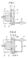
- Fig. 2 is a schematic sectional view showing a discharge restoring device for a recording head of an ink jet recording apparatus according to a first embodiment of the present invention;
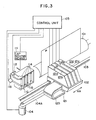
- Fig. 3 is a schematic constructural view showing an ink jet recording apparatus according to a second embodiment of the present invention; and
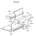
- Fig. 4 is a perspective view of an ink jet recording apparatus according to a third embodiment of the present invention.
- The present invention will now be fully and concretely explained in connection with embodiments shown in the drawings. However, it should be noted that the present invention is not limited to such embodiments, but various modifications may be adopted.
- First of all, a first embodiment shown in Fig. 2 will be explained.
- A cap member 11 is provided with a main suction port or
communication port 12 communicating with an upper portion of a space orcavity 8 of the cap member, and a second suction port orcommunication port 13 communicating with a lower portion of thecavity 8. Thecommudnication ports pump 14 through communication conduits orsuction paths cavity 8 through both of thecommunication ports suction path 12A is larger than that of thesuction path 13A. The suction paths i.e.,communication conduits communication conduit 12A is smaller than that of thecommunication conduit 13A. Alternatively, the channel resistances of the communication conduits may be differentiated as above, for example, by changing the dimensions of the suction port and/or making walls of the conduits with different rough surfaces. - With the construction mentioned above, when a
recording head 2 is moved to a home position in order to perform initial introduction of the recording liquid into acommon chamber 5 andliquid passages 6 of the head, the cap member 11 is shifted to cover adischarge face 3A of afront plate 3 of therecording head 2, then the air is sucked from thecavity 8 by thesuction pump 14, thereby decreasing the pressure in thecavity 8, with the result that the recording liquid is introduced from thecommon liquid chamber 5 andliquid passages 6 and then introduced into thecavity 8 throughdischarge openings 4. - In the illustrated first embodiment, during the suction operation, if the recording liquid is introduced in the manner shown in Fig. 1 to leave an air space or unfilled area in upper portions of the
chamber 5 andcavity 8, since the air is continuously sucked through themain communication port 12 by thesuction pump 14, thechamber 5,liquid passages 6 andcavity 8 are completely filled with the recording liquid as shown by a hatched portion in Fig. 2 for an extremely short time with less power, without leaving the air in the cavity as in the conventional device. Thereafter, by switching the pump to cooperate with thesecond communication conduit 13A, the recording liquid in thecavity 8 is completely drawn through the secondlower communication port 13, thus emptying the cavity so that the cap member 11 can be separated from therecording head 2 without contamination of the recording apparatus. - Next, a second embodiment of the present invention will be explained with reference to Fig. 3.
- Fig. 3 shows an ink jet recording apparatus according to the second embodiment of the present invention.
- In this ink jet recording apparatus, recording
head platen roller 101 as a conveying means. Therecording heads shiftable carriage 102 guided along aguide bar 103, so that the heads can be moved to perform a scanning operation. Thecarriage 102 is drive by adriving motor 104 through abelt 104A.Ink supply conduits 121 for supplying a predetermined inks to the corresponding recording heads are fixed to a conventionalflexible cable 120 to move together with it and are connected to corresponding ink tanks (not shown). - When the discharge restoring operation is performed, the
recording heads 121a-121d positioned in the home position are covered by acap member 110. The cap member includes cavities associated with the corresponding recording heads. The suction system of this embodiment is substantially the same as that of the first embodiment described above, except that avent valve 112 is provided in the communication conduit in its half way for communicating the corresponding cavity with the atmosphere. - That is to say, in operation, first of all, the
cap member 110 is shifted to cover the discharge openings of the recording heads by a shifting means 111. Thereafter, when a signal for initiating the restoring operation is inputted to acontrol unit 105, thecontrol unit 105 switches the three-way valves 112 to connectpumps 113 tocorresponding communication ports 114, then energizes thepump 113 to create the pressure difference between the cap member and the atmosphere, thus sucking the ink and/or air from the discharge openings of therecording heads 121a-121d through thecommunication ports cap member 110. - After a predetermined period of time is elapsed, the
control unit 105 switches the three-way valves 112 to vent the cavities of thecap member 110 to the atmosphere, thus sucking the inks filling the corresponding cavities through thelower communication ports 115 to empty the cavities and introduce the air into the cavities through thevalves 112. - In this way, according to this second embodiment, it is possible to maintain the discharge openings in a good condition and exhaust the inks in the
cap member 110 positively. While the three-way valve 112 and thepump 113 were shown only in association with therecording head 121a, theseelements - Further, each of the recording heads may include the ink tank therein and may be removably mounted on the carriage individually.
- Lastly, a third embodiment of the present invention will be explained with reference to Fig. 4 showing an ink jet recording apparatus of full-line type according to the third embodiment of the present invention.
- The recording apparatus includes a
recording head 212 which can perform the recording operation in stationary with respect to a recording medium P, and aroller 201 for conveying the recording medium P. - A
cap 210 is so constructed as to move and coverdischarge openings 212A of therecording head 212 in inoperative condition. Thecap 210 includescommunication ports suction pump 213 throughcorresponding communication conduits cap 210 with thesuction pump 213. Thecommunication port 215 is positioned in confronting relation to the leftmost (Fig. 4)discharge opening 212A, whereas thecommunication port 214 is positioned in confronting relation to therightmost discharge openings 212A. - In this way, according to this third embodiment, since the cap is communicated with the suction generating souce, at plural points, preferably, at both ends of the cap, it is possible to decrease the difference in suction forces for the respective discharge openings and to perform the effective restoring (suction) operation even in the recording head of full-line type.
- In the recording heads illustrated in the above-mentioned embodiments, it is preferably to adopt a method of producing images with a recording liquid that utilizes thermal energy for forming drops of the recording liquid. And, it is desirable to provide electrical-thermal converters in correspondence to the respective discharge openings to generate the thermal energy.
- Such recording head can preferably be used since it is easy to form multi-orifice construction.
- In the present invention the communication ports communicating with the interior if the cap member are provided at the upper portion of the cap member, "the upper portion" is defined to be above a position respective to a center, or a center in the direction of the gravity, of an array of discharging openings in respective recording heads or more preferably above a position corresponding to the uppermost discharge opening (Fig. 2).
- As mentioned above, according to the illustrated embodiments of the invention, since the communication port communicating with the suction means is arranged at least upper portion of a sealed space defined by mounting the cap member against the discharge face of the recording head, during the restoring operation for the recording head, the air is sucked from the sealed cavity through the upper portion thereof, whereby the recording liquid can be introduced into the cavity through all of the discharge openings including the upper ones, thus completely filling the liquid chamber and all of the liquid passages with the recording liquid. Further, by providing a plurality of communication ports and associated communication conduits communicating with the sealed cavity of the cap member, it is possible to perform the more effective initial introduction of the recording liquid and to facilitate the ejection of the recording liquid from the cavity of the cap member.
Claims (17)
a cap member for covering a plurality of discharge openings for discharging ink;
suction means for sucking the ink and/or air from said plurality of discharge openings through said cap member; and
a communication port provided at an upper portion of said cap member for communicating said suction means with the interior of said cap member.
a cap member for covering a plurality of discharge openings for discharging ink;
at least one suction means for sucking the ink and/or air from said plurality of discharge openings through said cap member; and
a plurality of communication ports provided in said cap member and communicating with said suction means,
wherein the ink and/or air are sucked through said communication ports.
a recording head having a plurality of discharge openings provided along an up standing direction for discharging ink;
a discharge recovery device as claimed in any preceding claim;
moving means for moving said cap member to a position where said cap member covers said plurality of discharge openings; and
drive means for driving said suction means in a state that said plurality of discharge openings are covered by said cap member by said moving means.
Priority Applications (1)
| Application Number | Priority Date | Filing Date | Title |
|---|---|---|---|
| EP93201119A EP0559296B1 (en) | 1987-11-17 | 1988-11-15 | Ink jet recording apparatus and discharge recovery device used with the same |
Applications Claiming Priority (4)
| Application Number | Priority Date | Filing Date | Title |
|---|---|---|---|
| JP28843387 | 1987-11-17 | ||
| JP288433/87 | 1987-11-17 | ||
| JP63285865A JP2817924B2 (en) | 1987-11-17 | 1988-11-14 | Ink jet recording device |
| JP285865/88 | 1988-11-14 |
Related Child Applications (2)
| Application Number | Title | Priority Date | Filing Date |
|---|---|---|---|
| EP93201119A Division EP0559296B1 (en) | 1987-11-17 | 1988-11-15 | Ink jet recording apparatus and discharge recovery device used with the same |
| EP93201119.0 Division-Into | 1993-04-17 |
Publications (3)
| Publication Number | Publication Date |
|---|---|
| EP0317267A2 true EP0317267A2 (en) | 1989-05-24 |
| EP0317267A3 EP0317267A3 (en) | 1989-11-15 |
| EP0317267B1 EP0317267B1 (en) | 1994-04-27 |
Family
ID=26556054
Family Applications (2)
| Application Number | Title | Priority Date | Filing Date |
|---|---|---|---|
| EP93201119A Expired - Lifetime EP0559296B1 (en) | 1987-11-17 | 1988-11-15 | Ink jet recording apparatus and discharge recovery device used with the same |
| EP88310777A Expired - Lifetime EP0317267B1 (en) | 1987-11-17 | 1988-11-15 | Ink jet recording apparatus and discharge recovery device used with the same |
Family Applications Before (1)
| Application Number | Title | Priority Date | Filing Date |
|---|---|---|---|
| EP93201119A Expired - Lifetime EP0559296B1 (en) | 1987-11-17 | 1988-11-15 | Ink jet recording apparatus and discharge recovery device used with the same |
Country Status (4)
| Country | Link |
|---|---|
| US (1) | US4952947A (en) |
| EP (2) | EP0559296B1 (en) |
| JP (1) | JP2817924B2 (en) |
| DE (2) | DE3889298T2 (en) |
Cited By (8)
| Publication number | Priority date | Publication date | Assignee | Title |
|---|---|---|---|---|
| EP0398347A2 (en) * | 1989-05-18 | 1990-11-22 | Canon Kabushiki Kaisha | An ink jet recording apparatus |
| EP0442483A2 (en) * | 1990-02-13 | 1991-08-21 | Canon Kabushiki Kaisha | Recovery system and ink jet recording apparatus provided with said recovery system |
| WO1993017867A1 (en) * | 1992-03-12 | 1993-09-16 | Willett International Limited | Method for flushing an ink flow system |
| EP0578822A1 (en) | 1991-03-29 | 1994-01-19 | Nippon Zeon Co., Ltd. | Thermoplastic saturated norbornene resin sheet and production thereof |
| US5670997A (en) * | 1992-07-24 | 1997-09-23 | Canon Kabushiki Kaisha | Recording means for enhancing removal of ink deposited on an ejection side surface thereof, ink jet recording apparatus having said recording means, and recovery method |
| EP1291183A1 (en) * | 2001-09-06 | 2003-03-12 | Canon Kabushiki Kaisha | Ink jet recording apparatus |
| US6722757B2 (en) * | 2001-09-07 | 2004-04-20 | Canon Kabushiki Kaisha | Ejection recovery device in ink jet printing apparatus, and ink jet printing apparatus |
| WO2005102708A1 (en) * | 2004-04-27 | 2005-11-03 | Matsushita Electric Industrial Co., Ltd. | Ink jet recorder and ink filling method |
Families Citing this family (20)
| Publication number | Priority date | Publication date | Assignee | Title |
|---|---|---|---|---|
| EP0444654B1 (en) * | 1990-02-28 | 1997-07-23 | Canon Kabushiki Kaisha | An ink jet apparatus |
| US5717444A (en) * | 1990-04-11 | 1998-02-10 | Canon Kabushiki Kaisha | Suction recovery device and ink jet recording apparatus using the device |
| US5051761A (en) * | 1990-05-09 | 1991-09-24 | Xerox Corporation | Ink jet printer having a paper handling and maintenance station assembly |
| EP0482775B1 (en) * | 1990-10-03 | 1996-04-10 | Canon Kabushiki Kaisha | Ink jet recording apparatus |
| US6007184A (en) * | 1990-10-03 | 1999-12-28 | Canon Kabushiki Kaisha | Ink jet recording head mounting and positioning arrangement |
| US5185614A (en) * | 1991-04-17 | 1993-02-09 | Hewlett-Packard Company | Priming apparatus and process for multi-color ink-jet pens |
| US5250962A (en) * | 1991-10-16 | 1993-10-05 | Xerox Corporation | Movable ink jet priming station |
| JP3021149B2 (en) * | 1991-12-19 | 2000-03-15 | キヤノン株式会社 | Ink jet recording means |
| JP3161155B2 (en) * | 1993-04-19 | 2001-04-25 | 富士ゼロックス株式会社 | Discharge performance maintenance device for color ink jet recording device |
| US6137504A (en) * | 1993-05-20 | 2000-10-24 | Canon Kabushiki Kaisha | Wiping and recovery of an ink jet head with inclined discharge port surface |
| US5532720A (en) * | 1993-09-15 | 1996-07-02 | Quad/Tech, Inc. | Solvent recovery system for ink jet printer |
| US5572243A (en) * | 1994-02-23 | 1996-11-05 | Xerox Corporation | Ink jet printer priming element |
| US5572245A (en) * | 1994-03-10 | 1996-11-05 | Hewlett-Packard Company | Protective cover apparatus for an ink-jet pen |
| US5682186A (en) * | 1994-03-10 | 1997-10-28 | Hewlett-Packard Company | Protective capping apparatus for an ink-jet pen |
| JPH07290724A (en) * | 1994-04-21 | 1995-11-07 | Fujitsu Ltd | Cleaning method and device of ink jet head |
| GB0011918D0 (en) * | 2000-05-17 | 2000-07-05 | Cambridge Consultants | Printing |
| US7465015B2 (en) * | 2004-12-06 | 2008-12-16 | Silverbrook Research Pty Ltd | Capping system for inkjet printhead assembly |
| JP2006192679A (en) * | 2005-01-13 | 2006-07-27 | Seiko Epson Corp | Liquid jetting apparatus and liquid suction device for liquid jetting apparatus |
| JP4844035B2 (en) * | 2005-07-27 | 2011-12-21 | 株式会社トヨトミ | humidifier |
| US7841686B2 (en) * | 2006-05-01 | 2010-11-30 | Canon Kabushiki Kaisha | Cartridge, recording apparatus, and method for determining amount of recording liquid remainder |
Citations (4)
| Publication number | Priority date | Publication date | Assignee | Title |
|---|---|---|---|---|
| US4510510A (en) * | 1982-04-13 | 1985-04-09 | Canon Kabushiki Kaisha | Inkjet printer |
| US4543589A (en) * | 1981-10-08 | 1985-09-24 | Canon Kabushiki Kaisha | Capping device for ink jet nozzle |
| US4684963A (en) * | 1984-06-08 | 1987-08-04 | Seiko Epson Kabushiki Kaisha | Nozzle cover assembly for an ink-on-demand type ink jet printer |
| EP0273362A1 (en) * | 1986-12-25 | 1988-07-06 | Canon Kabushiki Kaisha | Ink jet recording apparatus |
Family Cites Families (13)
| Publication number | Priority date | Publication date | Assignee | Title |
|---|---|---|---|---|
| DE3040055A1 (en) * | 1979-10-23 | 1981-05-14 | Canon K.K., Tokyo | INK PENS |
| US4383263A (en) * | 1980-05-20 | 1983-05-10 | Canon Kabushiki Kaisha | Liquid ejecting apparatus having a suction mechanism |
| JPS571769A (en) * | 1980-06-03 | 1982-01-06 | Canon Inc | For cleaning apparatus head of ink jet recorder |
| US4394669A (en) * | 1980-07-22 | 1983-07-19 | Canon Kabushiki Kaisha | Liquid jet recording apparatus |
| US4559543A (en) * | 1981-10-13 | 1985-12-17 | Canon Kabushiki Kaisha | Ink jet recording device modular frame |
| JPS58194568A (en) * | 1982-05-11 | 1983-11-12 | Canon Inc | Suction restoring apparatus |
| US4628333A (en) * | 1983-12-29 | 1986-12-09 | Canon Kabushiki Kaisha | Ink jet recording head and ink jet recorder |
| JPS60159057A (en) * | 1984-01-31 | 1985-08-20 | Canon Inc | Suction recovery device |
| DE3637991A1 (en) * | 1985-11-08 | 1987-05-14 | Canon Kk | INK-JET RECORDING DEVICE AND REGENERATION METHOD HERE |
| JPS62113559A (en) * | 1985-11-14 | 1987-05-25 | Canon Inc | Ink jet recorder |
| JPS62212155A (en) * | 1986-03-14 | 1987-09-18 | Hitachi Ltd | Printing apparatus |
| JP2528635B2 (en) * | 1986-04-09 | 1996-08-28 | キヤノン株式会社 | Inkjet device |
| JPS6475250A (en) * | 1987-09-17 | 1989-03-20 | Alps Electric Co Ltd | Suction recovery device of ink jet recorder |
-
1988
- 1988-11-14 JP JP63285865A patent/JP2817924B2/en not_active Expired - Fee Related
- 1988-11-15 DE DE3889298T patent/DE3889298T2/en not_active Expired - Fee Related
- 1988-11-15 US US07/271,312 patent/US4952947A/en not_active Expired - Lifetime
- 1988-11-15 DE DE3855082T patent/DE3855082T2/en not_active Expired - Fee Related
- 1988-11-15 EP EP93201119A patent/EP0559296B1/en not_active Expired - Lifetime
- 1988-11-15 EP EP88310777A patent/EP0317267B1/en not_active Expired - Lifetime
Patent Citations (4)
| Publication number | Priority date | Publication date | Assignee | Title |
|---|---|---|---|---|
| US4543589A (en) * | 1981-10-08 | 1985-09-24 | Canon Kabushiki Kaisha | Capping device for ink jet nozzle |
| US4510510A (en) * | 1982-04-13 | 1985-04-09 | Canon Kabushiki Kaisha | Inkjet printer |
| US4684963A (en) * | 1984-06-08 | 1987-08-04 | Seiko Epson Kabushiki Kaisha | Nozzle cover assembly for an ink-on-demand type ink jet printer |
| EP0273362A1 (en) * | 1986-12-25 | 1988-07-06 | Canon Kabushiki Kaisha | Ink jet recording apparatus |
Cited By (17)
| Publication number | Priority date | Publication date | Assignee | Title |
|---|---|---|---|---|
| EP0398347A3 (en) * | 1989-05-18 | 1991-05-08 | Canon Kabushiki Kaisha | An ink jet recording apparatus |
| US5963227A (en) * | 1989-05-18 | 1999-10-05 | Canon Kabushiki Kaisha | Ink jet recording apparatus |
| EP0398347A2 (en) * | 1989-05-18 | 1990-11-22 | Canon Kabushiki Kaisha | An ink jet recording apparatus |
| US5495271A (en) * | 1989-05-18 | 1996-02-27 | Canon Kabushiki Kaisha | Ink jet recording apparatus that individually controls ink ejection from plural recording heads during a non-recording operation |
| EP0442483B1 (en) * | 1990-02-13 | 1997-01-22 | Canon Kabushiki Kaisha | Recovery system and ink jet recording apparatus provided with said recovery system |
| EP0442483A2 (en) * | 1990-02-13 | 1991-08-21 | Canon Kabushiki Kaisha | Recovery system and ink jet recording apparatus provided with said recovery system |
| US5481283A (en) * | 1990-02-13 | 1996-01-02 | Canon Kabushiki Kaisha | Recovery system and ink jet recording apparatus provided with said recovery system |
| EP0578822B1 (en) * | 1991-03-29 | 1997-07-23 | Nippon Zeon Co., Ltd. | Thermoplastic saturated norbornene resin sheet and production thereof |
| EP0578822A1 (en) | 1991-03-29 | 1994-01-19 | Nippon Zeon Co., Ltd. | Thermoplastic saturated norbornene resin sheet and production thereof |
| WO1993017867A1 (en) * | 1992-03-12 | 1993-09-16 | Willett International Limited | Method for flushing an ink flow system |
| US5670997A (en) * | 1992-07-24 | 1997-09-23 | Canon Kabushiki Kaisha | Recording means for enhancing removal of ink deposited on an ejection side surface thereof, ink jet recording apparatus having said recording means, and recovery method |
| EP1291183A1 (en) * | 2001-09-06 | 2003-03-12 | Canon Kabushiki Kaisha | Ink jet recording apparatus |
| US6712447B2 (en) | 2001-09-06 | 2004-03-30 | Canon Kabushiki Kaisha | Ink jet recording apparatus |
| US6722757B2 (en) * | 2001-09-07 | 2004-04-20 | Canon Kabushiki Kaisha | Ejection recovery device in ink jet printing apparatus, and ink jet printing apparatus |
| WO2005102708A1 (en) * | 2004-04-27 | 2005-11-03 | Matsushita Electric Industrial Co., Ltd. | Ink jet recorder and ink filling method |
| US7490926B2 (en) | 2004-04-27 | 2009-02-17 | Panasonic Corporation | Ink jet recorder and ink filling method |
| US8147042B2 (en) | 2004-04-27 | 2012-04-03 | Miyakoshi Printing Machinery Co., Ltd. | Ink jet recorder and ink filling method |
Also Published As
| Publication number | Publication date |
|---|---|
| EP0559296B1 (en) | 1996-03-06 |
| EP0317267A3 (en) | 1989-11-15 |
| JPH02524A (en) | 1990-01-05 |
| US4952947A (en) | 1990-08-28 |
| JP2817924B2 (en) | 1998-10-30 |
| DE3889298D1 (en) | 1994-06-01 |
| EP0559296A3 (en) | 1993-09-15 |
| EP0317267B1 (en) | 1994-04-27 |
| DE3855082D1 (en) | 1996-04-11 |
| DE3889298T2 (en) | 1994-09-01 |
| DE3855082T2 (en) | 1996-09-19 |
| EP0559296A2 (en) | 1993-09-08 |
Similar Documents
| Publication | Publication Date | Title |
|---|---|---|
| EP0317267A2 (en) | Ink jet recording apparatus and discharge recovery device used with the same | |
| KR100346533B1 (en) | Ink Tank Cartridges for Ink-Jet Recording Devices | |
| US4965596A (en) | Ink jet recording apparatus with waste ink distribution paths to plural cartridges | |
| EP1876023B1 (en) | Inkjet printing apparatus and method of operation | |
| JPH0545424B2 (en) | ||
| US5185614A (en) | Priming apparatus and process for multi-color ink-jet pens | |
| US7794044B2 (en) | Ink jet printing apparatus | |
| EP0967083A2 (en) | Ink injection method, ink injection device, and ink-jet recording apparatus provided with the same | |
| US6247782B1 (en) | Ink jet recording device capable of reliably discharging air bubble during purging operations | |
| JPH0611542B2 (en) | Liquid jet recording head and liquid jet apparatus using the same | |
| JP4944296B2 (en) | Ink jet recording apparatus and discharge recovery method | |
| JPS58205773A (en) | Ink jet printer | |
| US6193356B1 (en) | Ink jet recording device capable of reliably discharging air bubble during purging operations | |
| JP2004291242A (en) | Inkjet recording device | |
| JP3058616B2 (en) | Ink jet recording device | |
| GB2315462A (en) | Ink cartridge having tapered bore | |
| JPH03142249A (en) | Multicolor ink-jet apparatus | |
| JPS63224957A (en) | Ink jet recorder | |
| JP4758571B2 (en) | Image recording device | |
| JPH09136437A (en) | Ink jet recording device, and ink recovery method for recording head | |
| JPS6277941A (en) | Operation method of ink jet recorder | |
| US10611160B2 (en) | Inkjet recording apparatus capable of smoothly supplying ink to first damper chamber and second damper chamber | |
| JPH1067117A (en) | Ink jet recorder | |
| JPH11115203A (en) | Ink jet recorder | |
| JPH08300677A (en) | Ink jet recording apparatus |
Legal Events
| Date | Code | Title | Description |
|---|---|---|---|
| PUAI | Public reference made under article 153(3) epc to a published international application that has entered the european phase |
Free format text: ORIGINAL CODE: 0009012 |
|
| AK | Designated contracting states |
Kind code of ref document: A2 Designated state(s): DE FR GB IT |
|
| PUAL | Search report despatched |
Free format text: ORIGINAL CODE: 0009013 |
|
| AK | Designated contracting states |
Kind code of ref document: A3 Designated state(s): DE FR GB IT |
|
| 17P | Request for examination filed |
Effective date: 19900405 |
|
| 17Q | First examination report despatched |
Effective date: 19911122 |
|
| GRAA | (expected) grant |
Free format text: ORIGINAL CODE: 0009210 |
|
| AK | Designated contracting states |
Kind code of ref document: B1 Designated state(s): DE FR GB IT |
|
| REF | Corresponds to: |
Ref document number: 3889298 Country of ref document: DE Date of ref document: 19940601 |
|
| ITF | It: translation for a ep patent filed |
Owner name: SOCIETA' ITALIANA BREVETTI S.P.A. |
|
| ET | Fr: translation filed | ||
| PLBE | No opposition filed within time limit |
Free format text: ORIGINAL CODE: 0009261 |
|
| STAA | Information on the status of an ep patent application or granted ep patent |
Free format text: STATUS: NO OPPOSITION FILED WITHIN TIME LIMIT |
|
| 26N | No opposition filed | ||
| REG | Reference to a national code |
Ref country code: GB Ref legal event code: IF02 |
|
| PGFP | Annual fee paid to national office [announced via postgrant information from national office to epo] |
Ref country code: GB Payment date: 20041101 Year of fee payment: 17 |
|
| PGFP | Annual fee paid to national office [announced via postgrant information from national office to epo] |
Ref country code: FR Payment date: 20041126 Year of fee payment: 17 |
|
| PGFP | Annual fee paid to national office [announced via postgrant information from national office to epo] |
Ref country code: DE Payment date: 20050121 Year of fee payment: 17 |
|
| PG25 | Lapsed in a contracting state [announced via postgrant information from national office to epo] |
Ref country code: IT Free format text: LAPSE BECAUSE OF NON-PAYMENT OF DUE FEES;WARNING: LAPSES OF ITALIAN PATENTS WITH EFFECTIVE DATE BEFORE 2007 MAY HAVE OCCURRED AT ANY TIME BEFORE 2007. THE CORRECT EFFECTIVE DATE MAY BE DIFFERENT FROM THE ONE RECORDED. Effective date: 20051115 Ref country code: GB Free format text: LAPSE BECAUSE OF NON-PAYMENT OF DUE FEES Effective date: 20051115 |
|
| PG25 | Lapsed in a contracting state [announced via postgrant information from national office to epo] |
Ref country code: DE Free format text: LAPSE BECAUSE OF NON-PAYMENT OF DUE FEES Effective date: 20060601 |
|
| GBPC | Gb: european patent ceased through non-payment of renewal fee |
Effective date: 20051115 |
|
| PG25 | Lapsed in a contracting state [announced via postgrant information from national office to epo] |
Ref country code: FR Free format text: LAPSE BECAUSE OF NON-PAYMENT OF DUE FEES Effective date: 20060731 |
|
| REG | Reference to a national code |
Ref country code: FR Ref legal event code: ST Effective date: 20060731 |