EP0315384B1 - Feed for thermal printing ribbon - Google Patents
Feed for thermal printing ribbon Download PDFInfo
- Publication number
- EP0315384B1 EP0315384B1 EP88310170A EP88310170A EP0315384B1 EP 0315384 B1 EP0315384 B1 EP 0315384B1 EP 88310170 A EP88310170 A EP 88310170A EP 88310170 A EP88310170 A EP 88310170A EP 0315384 B1 EP0315384 B1 EP 0315384B1
- Authority
- EP
- European Patent Office
- Prior art keywords
- ribbon
- item
- print head
- feeding
- length
- Prior art date
- Legal status (The legal status is an assumption and is not a legal conclusion. Google has not performed a legal analysis and makes no representation as to the accuracy of the status listed.)
- Expired - Lifetime
Links
Images

Classifications
-
- G—PHYSICS
- G07—CHECKING-DEVICES
- G07B—TICKET-ISSUING APPARATUS; FARE-REGISTERING APPARATUS; FRANKING APPARATUS
- G07B17/00—Franking apparatus
- G07B17/00459—Details relating to mailpieces in a franking system
- G07B17/00467—Transporting mailpieces
-
- B—PERFORMING OPERATIONS; TRANSPORTING
- B41—PRINTING; LINING MACHINES; TYPEWRITERS; STAMPS
- B41J—TYPEWRITERS; SELECTIVE PRINTING MECHANISMS, i.e. MECHANISMS PRINTING OTHERWISE THAN FROM A FORME; CORRECTION OF TYPOGRAPHICAL ERRORS
- B41J33/00—Apparatus or arrangements for feeding ink ribbons or like character-size impression-transfer material
- B41J33/14—Ribbon-feed devices or mechanisms
- B41J33/36—Ribbon-feed devices or mechanisms with means for adjusting feeding rate
-
- G—PHYSICS
- G07—CHECKING-DEVICES
- G07B—TICKET-ISSUING APPARATUS; FARE-REGISTERING APPARATUS; FRANKING APPARATUS
- G07B17/00—Franking apparatus
- G07B17/00185—Details internally of apparatus in a franking system, e.g. franking machine at customer or apparatus at post office
- G07B17/00193—Constructional details of apparatus in a franking system
- G07B2017/0025—Storage of, e.g. ribbon
-
- G—PHYSICS
- G07—CHECKING-DEVICES
- G07B—TICKET-ISSUING APPARATUS; FARE-REGISTERING APPARATUS; FRANKING APPARATUS
- G07B17/00—Franking apparatus
- G07B17/00459—Details relating to mailpieces in a franking system
- G07B17/00508—Printing or attaching on mailpieces
- G07B2017/00516—Details of printing apparatus
- G07B2017/00524—Printheads
- G07B2017/0054—Thermal printhead
Definitions
- This invention relates to the feeding of ribbons carrying ink for printing and in particular to the feeding of thermal transfer printing ribbons.
- Ribbons are utilised to carry a supply of ink to a printing station at which printing elements cause ink to be transferred from the ribbon to the surface of an article upon which printing is to be effected.
- the ink is carried in a layer on the surface of a ribbon substrate and the ink is transferred from the ribbon to the surface of the article by the application of heat to the ribbon.
- thermal transfer ribbons With commonly available thermal transfer ribbons, a total transfer of ink occurs at each printing operation so that the ribbon can be used only once. If printing is effected in a serial manner in which the article is moved past the printing elements and the required print impression is built up in a series of printing operations, the ribbon is fed with and at the same speed as the feeding of the article past the printing station.
- the ribbon is also held stationery during the printing operation and is fed during the interval between consecutive printing operations. In each case, the ribbon is fed by approximately the length of print impression for each printing operation. Because the ink corresponding to the pattern of the print impression is totally removed from the ribbon during a print operation the ribbon cannot be re-used because areas of the ribbon from which ink has been totally removed may coincide with areas of the ribbon required for printing a subsequent impression. If such a ribbon was re-used the printing would be defective and unreliable.
- the ribbon is usually contained on a reel or spool from which it is unwound in use and rewound onto another reel or spool.
- thermal transfer ribbons need to be fed in the same direction as the article on which printing is to be effected, it is not practicable to reverse the direction of feed of the ribbon for each successive transit of the ribbon. Consequently, when the end of the ribbon is reached, subsequent printing operations are delayed by the time taken to rewind the ribbon. A further difficulty arises from the flimsy nature of the ribbon substrate. The substrate tends to become distorted during printing operations and it is difficult to achieve satisfactory rewinding of the ribbon without damage occurring to the substrate of the ribbon.
- the specification of DE 36 35 779 discloses a thermal printing device in which a print head traverses a platen and prints bi-directionally.
- a thermal ribbon is carried by a print head carriage and during each printing traverse by the print head, the ribbon is fed so as to be stationery relative to a sheet being printed and hence as the print head traverses the platen and prints alternately in opposite directions the thermal ribbon is fed alternately in opposite directions.
- a portion of the thermal ribbon is used a number of times in a series of traverses of the print head.
- the length of ribbon fed in each direction is determined by the length of traverse of the print head.
- the print head Periodically the print head is moved to a home position at which the ribbon is fed to bring into use a new unused length of ribbon which is then used a number of times in a plurality of bi-directional traverses of the print head.
- a length of ribbon is used a number of times in a series of traverses and then the ribbon is fed to remove the used ribbon from further use and to bring a new unused length of ribbon into use.
- IBM Technical Disclosure Bulletin Vol. 24 No. 1A June 1981 pages 401 - 403 discloses ribbon drive apparatus for a printer in which a ribbon is drawn from a supply reel onto a take-up reel. Steppers motors are coupled to the supply and take-up reels. When the take-up reel motor is enrgised, the motor coupled to the supply reel acts as a pulse generator to detect when the end of the ribbon is reached and to control reversal of feed of the ribbon.
- a thermal printing device including a thermal print head operable to print on a surface of an item by selective application of heat to a thermal transfer ribbon to transfer selected areas of ink from the ribbon to the surface of the item; a thermal transfer ribbon wound upon a supply spool; ribbon feeding means operative to feed a length of said ribbon from the supply spool between the print head and the item for each printing operation is characterised in that during printing on each item first ribbon feeding means feeds the ribbon only in a first direction and in that second ribbon feeding means including a rewind motor is operated during intervals between printing on successive items to drive the supply spool to rewind the ribbon onto the supply spool and thereby to feed the ribbon in a second direction opposite to said first direction by an item together with a first length of said ribbon in a first direction past the print head and in that during an interval following printing on an item said control means operates said actuating means to move the impression means away from the print head to release the ribbon and the item and operates the rewind motor to drive the supply the supply
- a franking machine including a thermal print head operable by print signals; means to guide a thermal transfer inked ribbon past the thermal print head; feeding means to feed a mail item in a first direction past the thermal print head with the thermal transfer ribbon interposed between the mail item and the print head; pressure means actuable to press the mail item toward the print head into engagement with the ribbon, said engagement being effective to feed the ribbon with the mail item in said first direction is characterised by the provision of rewind means operable to feed the ribbon in a second direction opposite to said first direction; accounting and control means operable to actuate the pressure means and to generate print signals to selectively heat elements of the print head to cause transfer of ink from the ribbon to the mail item to form a franking impression thereon during feeding of the mail item together with a first length of the ribbon past the print head; the accounting and control means being operative to terminate actuation of the pressure means to release the mail item and the ribbon; sensor means operative to generate signals indicative of the length of ribbon fed in said first and
- a method of printing using a thermal print head selectively operable to transfer ink from a thermal transfer inked ribbon to the surface of an item in which the ribbon is made available a plurality of times for ink transfer including the steps of causing relative motion between an item together with the inked ribbon and the print head with the item in ink transfer engagement with the ribbon is characterised by the steps of feeding a first length of ribbon from ribbon supply means together with a first item in a first direction past the print head; selectively operating the print head to transfer ink from the first length of ribbon to the surface of the item to form a print impression on said first item; releasing the first item from engagement with the ribbon; feeding the ribbon in a second direction opposite to said first direction by an amount related to said first length; feeding a second item together with the inked ribbon past the print head with the second item in ink transfer engagement with the ribbon and selectively operating the print head to effect further transfer of ink from at least a part of said first length of ribbon to the second item.
- a method of printing using a thermal print head selectively operable to transfer ink from a thermal transfer inked ribbon to the surface of items, the ribbon being made available a plurality of times for ink transfer is characterised by successively performing a group of steps comprising the steps of feeding a first length of the inked ribbon in a first direction from ribbon supply means to ribbon take up means; feeding an item past the print head in a second direction opposite to said first direction; feeding a second length of the inked ribbon in said second direction from said ribbon take up means to said ribbon supply means and in ink transfer relationship with said item during the feeding of said item past the print head, the first and second lengths of said ribbon being of predetermined relationship so that the second length of ribbon fed in one group of steps includes a part of the second length of ribbon fed in a preceding group of steps; selectively operating the print head to transfer ink from the second length of the ribbon including transfer of ink from said part of the second length in a preceding group of steps to said item to form a print
- a printing device has a thermal print head 10 containing a plurality of print elements 10a which can be selectively heated by the passage of electric current therethrough.
- thermal print heads are well known and it is believed to be un-necessary to describe the construction and operation thereof.
- Items 11 upon which printing is to be effected are fed past the print head 10 in the direction of arrow 12 by means of feed rollers 13, of which one is shown in Figures 2 and 3, and a co-operating impression roller 14.
- the feed rollers 13 are positioned on each side of the print head 10 and the impression roller 14 is of greater width than the print head and is urged resiliently toward the print head and the feed rollers.
- the feed rollers are driven by an electric motor (not shown).
- the print elements 10a in the present embodiment are disposed along a line extending transverse to the direction of feeding aligned substantially with a line along which the impression roller 14 presses toward the head.
- a thermal transfer ribbon 15 wound on a rotatable supply spool 16 passes from the spool 16 along the face of the print head 10 and thence to a rotatable take up spool 17.
- Ribbon guides 18 are provided at each end of the print head.
- the ribbon is a multi-strike ribbon in which only a portion of the ink is removed from areas corresponding to selected printing elements in a single printing operation.
- Multi-strike ribbons may contain the ink in a plurality of layers. Accordingly the ribbon can be used a number of times until the ink has been reduced to a level at which printing is expected to be unreliable.
- the feeding of the ribbon is controlled in such a manner as to result in repeated use of the ribbon during a single passage of the total length of the ribbon from the supply spool to the take up spool.
- the impression roller 14 is mounted in such a manner that it may be moved toward and away from the print head and feed rollers 13.
- it may be rotatably mounted on a pair of pivotable arms 24 and an electro-mechanical driver 25, mechanically connected to the arms 24 by suitable drive means, is provided to move the impression roller toward the print head to effect feeding of the item during printing on the item.
- the electromechanical driver 25 is actuated to move the impression roller 14 away from the print head to allow the item to continue moving in the direction of arrow 12 without drawing further ribbon from the spool 16. This also releases the ribbon from constraint and allows the ribbon to be partially rewound onto the supply spool 16 while also allowing the item 11 to be fed away from the print head in the direction of arrow 12.
- spring means may be provided to urge the impression roller toward the print head and the electro-mechanical driver is arranged to move the impression roller away from the print head against the action of the spring means
- An encoder disc 20 is secured to the shaft of the supply spool 16 and rotates with the supply spool.
- a sensor 21 responds to rotation of the encoder disc and generates electrical signals indicative of the amount of rotation of the supply spool 16.
- a rewind motor 22 is coupled to the shaft of the supply spool and is operable to withdraw the ribbon from the take up spool and to rewind it on the supply spool.
- a microprocessor 23 receives the signals from the sensor 21 and controls the operation of the rewind motor such as to rewind a proportion of the length of ribbon used during the immediately preceding printing operation. This may be accomplished by programming the microprocessor to count electrical pulses from the sensor as the encoder disc rotates during withdrawal of the ribbon from the supply spool and from this count to generate a value equal to a predetermined fraction of the count. During energisation of the rewind motor to rewind the ribbon onto the supply spool, the microprocessor is programmed to count pulses from the sensor and to compare this count with the fraction of count generated during unwinding of the ribbon. When these values are equal, energisation of the rewind motor is terminated.
- the positions of the supply and take up spools are interchanged.
- a short length of unused ribbon initially is wound onto the take up spool.
- the take up spool is driven by the rewind motor to wind a length of ribbon onto the take up spool which is greater than the length of ribbon withdrawn during printing.
- the length of ribbon fed in the interval between printing operations is a fraction, greater than unity, of the length of ribbon fed during each printing operation.
- the encoder disc is described as being mounted to rotate with the supply spool, if desired, the encoder disc may be mounted on the shaft of the take up spool so as to rotate with the take up spool. Alternatively, the encoder disc need not be coupled to one of the spools but may be coupled to an additional roller contacting the ribbon so as to be rotated by feeding of the ribbon.
- the electronic circuitry for the franking machine includes the microprocessor 23, a keyboard 26 for entering data and commands into the microprocessor and a display device 27 for displaying data and instruction information to a user of the machine.
- the circuitry also includes memories 28 and 29 for storing accounting data relating to the use of the franking machine in franking operations.
- the data stored in memory 28 is replicated in memory 29 in order to ensure integrity of the stored data.
- a sensor 30 is mounted, upstream of the drive and pressure rollers 13, 14 ( Figure 2), adjacent the feed path of the items 11 to detect the leading edge of an item 11 being fed to the print head 10.
- An electrical signal from the sensor 30 indicating detection of an item is input to the microprocessor 23 and in response the microprocessor actuates the electro-mechanical driver 25 to move the pressure roller toward the feed roller 13 and print head 10.
- the delays in the system are such that the leading end of the item is between the pressure and feed rollers as the former is moved toward the feed rollers.
- the microprocessor After a predetermined time period from sensing of the leading edge of the item, the microprocessor outputs print signals to the print elements 10a of the print head via print head driver circuits 31 to cause the print elements to effect transfer of ink from the ribbon to the surface of the item as the item together with the ribbon is fed past the print elements.
- Pulse signals from the sensor 21 resulting from rotation of the reel 16 are input to the microprocessor.
- these pulse signals are accumulated in a register 31 to provide a count representing the length of ribbon used.
- the microprocessor actuates the electro-mechanical driver to move the pressure roller 14 away from the feed roller 13.
- the microprocessor reads the count stored in the register 31, calculates a predetermined fraction of the count and then actuates the rewind motor 22 to rewind the ribbon until pulse signals from the sensor 21 during rewinding equal the value of the calculated fraction.
- the electrical pulse signals from the sensor 21 may be utilised to initiate an end of ribbon warning.
- a register 32 in or connected to the microprocessor 23 is set to store a value representing the amount of rotation of the spool needed to unwind the ribbon to near the end of the ribbon.
- the supply spool will be wound with a substantially uniform number of turns of ribbon.
- the value stored in the register 32 is a constant which may be set automatically by a signal generated upon installation of a ribbon. This signal may be generated by an input on the keyboard by the user of the machine upon installation of a new ribbon or if desired the signal could be generated by means responsive to the installation of a ribbon.
- Signals from the sensor 21 during unwinding of the ribbon from the supply spool cause the microprocessor to decrement the value in the register 32 whereas signals from the sensor during rewinding of the ribbon cause the value in the register to be incremented.
- a predetermined limit for example zero
- an end of ribbon warning is initiated and this may be displayed to the user on the display device 27.
- the print head comprises a single line of print elements extending transversely to the direction of feeding of the item 11 and printing is effected serially as the item is moved past the print heads.
- the print head may comprise print elements operable at the same time to print the entire impression.
- the printing device described hereinbefore is particularly suitable for use in a postal franking machine in which the print head is controlled by the franking meter of the machine to print franking impressions and other information on mail items such as envelopes or labels. While it is preferred to partially rewind the ribbon after printing has been completed on an item, if desired the rewinding may be performed less frequently for example after each second or third item of a series of items. Thus a printing operation may consist of printing on a group of one or more items in succession and the partial rewinding is effected in intervals between printing on groups of items.
Description
- This invention relates to the feeding of ribbons carrying ink for printing and in particular to the feeding of thermal transfer printing ribbons.
- Ribbons are utilised to carry a supply of ink to a printing station at which printing elements cause ink to be transferred from the ribbon to the surface of an article upon which printing is to be effected. In thermal transfer printing processes, the ink is carried in a layer on the surface of a ribbon substrate and the ink is transferred from the ribbon to the surface of the article by the application of heat to the ribbon. With commonly available thermal transfer ribbons, a total transfer of ink occurs at each printing operation so that the ribbon can be used only once. If printing is effected in a serial manner in which the article is moved past the printing elements and the required print impression is built up in a series of printing operations, the ribbon is fed with and at the same speed as the feeding of the article past the printing station. On the other hand if the required impression is printed in a single printing operation in which the article is held stationery at a printing station, the ribbon is also held stationery during the printing operation and is fed during the interval between consecutive printing operations. In each case, the ribbon is fed by approximately the length of print impression for each printing operation. Because the ink corresponding to the pattern of the print impression is totally removed from the ribbon during a print operation the ribbon cannot be re-used because areas of the ribbon from which ink has been totally removed may coincide with areas of the ribbon required for printing a subsequent impression. If such a ribbon was re-used the printing would be defective and unreliable. The ribbon is usually contained on a reel or spool from which it is unwound in use and rewound onto another reel or spool. When the total length of the ribbon has been used, it is necessary to replace the ribbon with a new unused ribbon and this results in interruption in the use of the printing device. In order to allow a ribbon to be used for a larger number of printing operations multi-strike ribbons are being developed. In one form of these multi-strike ribbons the ink is contained in a plurality of layers. Only a portion of the ink, for example one layer, is removed in the course of a printing operation whereby the length of ribbon may be used a number of times. However while this provides a saving in terms of replacing the ribbon, after each transit of the length of the ribbon past the printing station the ribbon needs to be rewound prior to the next transit of the ribbon. It will be appreciated that because thermal transfer ribbons need to be fed in the same direction as the article on which printing is to be effected, it is not practicable to reverse the direction of feed of the ribbon for each successive transit of the ribbon. Consequently, when the end of the ribbon is reached, subsequent printing operations are delayed by the time taken to rewind the ribbon. A further difficulty arises from the flimsy nature of the ribbon substrate. The substrate tends to become distorted during printing operations and it is difficult to achieve satisfactory rewinding of the ribbon without damage occurring to the substrate of the ribbon.
- The specification of DE 36 35 779 discloses a thermal printing device in which a print head traverses a platen and prints bi-directionally. A thermal ribbon is carried by a print head carriage and during each printing traverse by the print head, the ribbon is fed so as to be stationery relative to a sheet being printed and hence as the print head traverses the platen and prints alternately in opposite directions the thermal ribbon is fed alternately in opposite directions. As a result a portion of the thermal ribbon is used a number of times in a series of traverses of the print head. The length of ribbon fed in each direction is determined by the length of traverse of the print head. Periodically the print head is moved to a home position at which the ribbon is fed to bring into use a new unused length of ribbon which is then used a number of times in a plurality of bi-directional traverses of the print head. Thus a length of ribbon is used a number of times in a series of traverses and then the ribbon is fed to remove the used ribbon from further use and to bring a new unused length of ribbon into use.
- IBM Technical Disclosure Bulletin Vol. 24 No. 1A June 1981 pages 401 - 403 discloses ribbon drive apparatus for a printer in which a ribbon is drawn from a supply reel onto a take-up reel. Steppers motors are coupled to the supply and take-up reels. When the take-up reel motor is enrgised, the motor coupled to the supply reel acts as a pulse generator to detect when the end of the ribbon is reached and to control reversal of feed of the ribbon.
- According to one aspect of the invention a thermal printing device including a thermal print head operable to print on a surface of an item by selective application of heat to a thermal transfer ribbon to transfer selected areas of ink from the ribbon to the surface of the item; a thermal transfer ribbon wound upon a supply spool; ribbon feeding means operative to feed a length of said ribbon from the supply spool between the print head and the item for each printing operation is characterised in that during printing on each item first ribbon feeding means feeds the ribbon only in a first direction and in that second ribbon feeding means including a rewind motor is operated during intervals between printing on successive items to drive the supply spool to rewind the ribbon onto the supply spool and thereby to feed the ribbon in a second direction opposite to said first direction by an item together with a first length of said ribbon in a first direction past the print head and in that during an interval following printing on an item said control means operates said actuating means to move the impression means away from the print head to release the ribbon and the item and operates the rewind motor to drive the supply spool to feed the ribbon in a second direction opposite to said first direction by a second length equal to a predetermined fraction of said first length whereby each part of said ribbon is fed past the print head in the first direction a plurality of times for printing on a succession of items.
- According to a second aspect of the invention a franking machine including a thermal print head operable by print signals; means to guide a thermal transfer inked ribbon past the thermal print head; feeding means to feed a mail item in a first direction past the thermal print head with the thermal transfer ribbon interposed between the mail item and the print head; pressure means actuable to press the mail item toward the print head into engagement with the ribbon, said engagement being effective to feed the ribbon with the mail item in said first direction is characterised by the provision of rewind means operable to feed the ribbon in a second direction opposite to said first direction; accounting and control means operable to actuate the pressure means and to generate print signals to selectively heat elements of the print head to cause transfer of ink from the ribbon to the mail item to form a franking impression thereon during feeding of the mail item together with a first length of the ribbon past the print head; the accounting and control means being operative to terminate actuation of the pressure means to release the mail item and the ribbon; sensor means operative to generate signals indicative of the length of ribbon fed in said first and second directions; said accounting and control means being responsive to said sensor means to actuate the rewind means after completion of printing the franking impression to feed a second length of the ribbon in the second direction, said second length being a fraction of said first length.
- According to a third aspect of the invention a method of printing using a thermal print head selectively operable to transfer ink from a thermal transfer inked ribbon to the surface of an item in which the ribbon is made available a plurality of times for ink transfer including the steps of causing relative motion between an item together with the inked ribbon and the print head with the item in ink transfer engagement with the ribbon is characterised by the steps of feeding a first length of ribbon from ribbon supply means together with a first item in a first direction past the print head; selectively operating the print head to transfer ink from the first length of ribbon to the surface of the item to form a print impression on said first item; releasing the first item from engagement with the ribbon; feeding the ribbon in a second direction opposite to said first direction by an amount related to said first length; feeding a second item together with the inked ribbon past the print head with the second item in ink transfer engagement with the ribbon and selectively operating the print head to effect further transfer of ink from at least a part of said first length of ribbon to the second item.
- According to a fourth aspect of the invention a method of printing using a thermal print head selectively operable to transfer ink from a thermal transfer inked ribbon to the surface of items, the ribbon being made available a plurality of times for ink transfer, is characterised by successively performing a group of steps comprising the steps of feeding a first length of the inked ribbon in a first direction from ribbon supply means to ribbon take up means; feeding an item past the print head in a second direction opposite to said first direction; feeding a second length of the inked ribbon in said second direction from said ribbon take up means to said ribbon supply means and in ink transfer relationship with said item during the feeding of said item past the print head, the first and second lengths of said ribbon being of predetermined relationship so that the second length of ribbon fed in one group of steps includes a part of the second length of ribbon fed in a preceding group of steps; selectively operating the print head to transfer ink from the second length of the ribbon including transfer of ink from said part of the second length in a preceding group of steps to said item to form a print impression on said item; and releasing said item from engagement with the ribbon after forming the print impression thereon.
- An embodiment of the invention will now be described by way of example with reference to the drawings in which:-
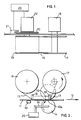
- Figure 1 is a plan view of a printing device incorporating a ribbon feed
- Figure 2 is a front elevation of the printing device
- Figure 3 is a front elevation similar to that shown in Figure 2 showing the printing device during rewinding of the ribbon, and
- Figure 4 is a block diagram of the electronic circuitry of a franking machine incorporating the printing device of Figures 1 and 2.
- Referring to the drawings, in particular Figures 1 and 2, a printing device has a
thermal print head 10 containing a plurality ofprint elements 10a which can be selectively heated by the passage of electric current therethrough. Such thermal print heads are well known and it is believed to be un-necessary to describe the construction and operation thereof.Items 11 upon which printing is to be effected are fed past theprint head 10 in the direction ofarrow 12 by means offeed rollers 13, of which one is shown in Figures 2 and 3, and aco-operating impression roller 14. Thefeed rollers 13 are positioned on each side of theprint head 10 and theimpression roller 14 is of greater width than the print head and is urged resiliently toward the print head and the feed rollers. The feed rollers are driven by an electric motor (not shown). Theprint elements 10a in the present embodiment are disposed along a line extending transverse to the direction of feeding aligned substantially with a line along which theimpression roller 14 presses toward the head. - A
thermal transfer ribbon 15 wound on arotatable supply spool 16 passes from thespool 16 along the face of theprint head 10 and thence to a rotatable take upspool 17.Ribbon guides 18 are provided at each end of the print head. As anitem 11 is fed past the print head by thefeed rollers 13 and co-operatingimpression roller 14, theribbon 15 is pulled, due to frictional contact with the item, from thesupply spool 16 so as to be fed between the print head and the item at the same speed as that of the item. Repeated selection and heating of the selectedprint elements 10a results in heating of selected dot areas of the ribbon and transfer of ink from those dot areas to the surface of the item. Thus as the item is fed past the line of print elements dots are printed whereby the required printed characters and patterns are built up serially on the surface of the item. Amotor 19 applies a torque to the shaft of the take upspool 17 so as to wind the used ribbon onto thespool 17. The ribbon is a multi-strike ribbon in which only a portion of the ink is removed from areas corresponding to selected printing elements in a single printing operation. Multi-strike ribbons may contain the ink in a plurality of layers. Accordingly the ribbon can be used a number of times until the ink has been reduced to a level at which printing is expected to be unreliable. In order to overcome the disadvantage of needing to rewind and reload the ribbon after each time the full length of ribbon has been unwound from the supply spool the feeding of the ribbon is controlled in such a manner as to result in repeated use of the ribbon during a single passage of the total length of the ribbon from the supply spool to the take up spool. - The
impression roller 14 is mounted in such a manner that it may be moved toward and away from the print head andfeed rollers 13. For example it may be rotatably mounted on a pair ofpivotable arms 24 and an electro-mechanical driver 25, mechanically connected to thearms 24 by suitable drive means, is provided to move the impression roller toward the print head to effect feeding of the item during printing on the item. After printing upon the item has been completed, theelectromechanical driver 25 is actuated to move theimpression roller 14 away from the print head to allow the item to continue moving in the direction ofarrow 12 without drawing further ribbon from thespool 16. This also releases the ribbon from constraint and allows the ribbon to be partially rewound onto thesupply spool 16 while also allowing theitem 11 to be fed away from the print head in the direction ofarrow 12. Alternatively if desired, spring means may be provided to urge the impression roller toward the print head and the electro-mechanical driver is arranged to move the impression roller away from the print head against the action of the spring means Anencoder disc 20 is secured to the shaft of thesupply spool 16 and rotates with the supply spool. Asensor 21 responds to rotation of the encoder disc and generates electrical signals indicative of the amount of rotation of thesupply spool 16. Arewind motor 22 is coupled to the shaft of the supply spool and is operable to withdraw the ribbon from the take up spool and to rewind it on the supply spool. Amicroprocessor 23 receives the signals from thesensor 21 and controls the operation of the rewind motor such as to rewind a proportion of the length of ribbon used during the immediately preceding printing operation. This may be accomplished by programming the microprocessor to count electrical pulses from the sensor as the encoder disc rotates during withdrawal of the ribbon from the supply spool and from this count to generate a value equal to a predetermined fraction of the count. During energisation of the rewind motor to rewind the ribbon onto the supply spool, the microprocessor is programmed to count pulses from the sensor and to compare this count with the fraction of count generated during unwinding of the ribbon. When these values are equal, energisation of the rewind motor is terminated. - It will be appreciated that the amount of rotation of the supply spool during a printing operation, assuming the length of the print impression is constant, will increase as the length of ribbon remaining on the spool decreases. The effect of this is that for successive printing operations the count from the sensor increases and similarly the value of the fraction of the count increases in proportion.
- In a modification, the positions of the supply and take up spools are interchanged. A short length of unused ribbon initially is wound onto the take up spool. After printing of each item, during which a length of ribbon is withdrawn from the take up spool, the take up spool is driven by the rewind motor to wind a length of ribbon onto the take up spool which is greater than the length of ribbon withdrawn during printing. Thus in this modification the length of ribbon fed in the interval between printing operations is a fraction, greater than unity, of the length of ribbon fed during each printing operation.
- Although the encoder disc is described as being mounted to rotate with the supply spool, if desired, the encoder disc may be mounted on the shaft of the take up spool so as to rotate with the take up spool. Alternatively, the encoder disc need not be coupled to one of the spools but may be coupled to an additional roller contacting the ribbon so as to be rotated by feeding of the ribbon.
- Referring now to Figure 4, the electronic circuitry for the franking machine includes the
microprocessor 23, akeyboard 26 for entering data and commands into the microprocessor and adisplay device 27 for displaying data and instruction information to a user of the machine. The circuitry also includesmemories memory 28 is replicated inmemory 29 in order to ensure integrity of the stored data. Asensor 30 is mounted, upstream of the drive andpressure rollers 13, 14 (Figure 2), adjacent the feed path of theitems 11 to detect the leading edge of anitem 11 being fed to theprint head 10. An electrical signal from thesensor 30 indicating detection of an item is input to themicroprocessor 23 and in response the microprocessor actuates the electro-mechanical driver 25 to move the pressure roller toward thefeed roller 13 andprint head 10. The delays in the system are such that the leading end of the item is between the pressure and feed rollers as the former is moved toward the feed rollers. After a predetermined time period from sensing of the leading edge of the item, the microprocessor outputs print signals to theprint elements 10a of the print head via printhead driver circuits 31 to cause the print elements to effect transfer of ink from the ribbon to the surface of the item as the item together with the ribbon is fed past the print elements. Pulse signals from thesensor 21 resulting from rotation of thereel 16 are input to the microprocessor. During feeding of the ribbon during a printing operation, these pulse signals are accumulated in aregister 31 to provide a count representing the length of ribbon used. Upon completion of the printing operation on the item currently being fed past the print head, the microprocessor actuates the electro-mechanical driver to move thepressure roller 14 away from thefeed roller 13. The microprocessor reads the count stored in theregister 31, calculates a predetermined fraction of the count and then actuates therewind motor 22 to rewind the ribbon until pulse signals from thesensor 21 during rewinding equal the value of the calculated fraction. - The electrical pulse signals from the
sensor 21 may be utilised to initiate an end of ribbon warning. When an unused ribbon is installed in the printing device aregister 32 in or connected to themicroprocessor 23 is set to store a value representing the amount of rotation of the spool needed to unwind the ribbon to near the end of the ribbon. During manufacture of the ribbon the supply spool will be wound with a substantially uniform number of turns of ribbon. Accordingly the value stored in theregister 32 is a constant which may be set automatically by a signal generated upon installation of a ribbon. This signal may be generated by an input on the keyboard by the user of the machine upon installation of a new ribbon or if desired the signal could be generated by means responsive to the installation of a ribbon. Signals from thesensor 21 during unwinding of the ribbon from the supply spool cause the microprocessor to decrement the value in theregister 32 whereas signals from the sensor during rewinding of the ribbon cause the value in the register to be incremented. When the value in the register is decremented to a predetermined limit, for example zero, an end of ribbon warning is initiated and this may be displayed to the user on thedisplay device 27. - In the embodiment described hereinbefore, the print head comprises a single line of print elements extending transversely to the direction of feeding of the
item 11 and printing is effected serially as the item is moved past the print heads. However if desired the print head may comprise print elements operable at the same time to print the entire impression. With such a print head the item is fed to a printing position confronting the print head and the ribbon is drawn by the feeding of the item to the printing position. The item and ribbon are then held stationery and pressed toward the print head by an impression pad while the printing operation is effected. After the printing operation the impression pad is moved away from the print head to release the item and the ribbon. The item is fed in the direction ofarrow 12 away from the printing position and the ribbon is partially rewound as hereinbefore described. - The printing device described hereinbefore is particularly suitable for use in a postal franking machine in which the print head is controlled by the franking meter of the machine to print franking impressions and other information on mail items such as envelopes or labels. While it is preferred to partially rewind the ribbon after printing has been completed on an item, if desired the rewinding may be performed less frequently for example after each second or third item of a series of items. Thus a printing operation may consist of printing on a group of one or more items in succession and the partial rewinding is effected in intervals between printing on groups of items.
Claims (12)
- A thermal printing device including a thermal print head (10) operable in a print operation to print on a surface of an item (11) by selective application of heat to a thermal transfer ribbon to transfer selected areas of ink from the ribbon to the surface of the item; a thermal transfer ribbon (15) wound upon a supply spool (16); ribbon feeding means (13, 14) operative to feed said ribbon between the print head (10) and the item (11)
characterised in that the ribbon feeding means includes impression means (14) movable toward and away from the print head by actuating means (25), a rewind motor (22) operable to drive the supply spool to rewind the ribbon thereon and control means (23) operative during printing on each item to operate the actuating means (25) to urge the impression means toward the print head to bring the item into engagement with the ribbon and to feed the item together with a first length of said ribbon in a first direction (12) past the print head and in that during an interval following printing on an item said control means operates said actuating means to move the impression means (14) away from the print head to release the ribbon and the item and operates the rewind motor (22) to drive the supply spool (16) to feed the ribbon in a second direction opposite to said first direction by a second length equal to a predetermined fraction of said first length whereby each part of said ribbon is fed past the print head in the first direction a plurality of times for printing on a succession of items. - A thermal printing device as claimed in claim 1 further characterised by sensing means (20, 21) responsive to feeding of the ribbon in the first and second directions to generate electrical signals; and control means (23, 31) operative in response to said electrical signals to control feeding of said ribbon in said second direction by the second ribbon feeding means.
- A thermal printing device as claimed in claim 2 further characterised in that the sensing means (20, 21) is responsive to feeding of the ribbon in the first direction to generate first signals representing an extent to which the ribbon (15) is fed in the first direction (12) and is responsive to feeding of the ribbon in the second direction to generate second signals representing an extent to which the ribbon is fed in the second direction; and in that
control means (23) is responsive to said first signals and operative after completion of formation of the print impression to operate the second ribbon feed means (22) to feed the ribbon in said second direction until said second signals have a predetermined relationship to said first signals. - A thermal printing device as claimed in claim 1 or 2 further characterised by an encoder disc (20) mounted to rotate with the supply spool (16) and a sensor (21) operative in response to rotation of the encoder disc to generate electrical signals indicative of the amount of rotation of the disc and supply spool.
- A thermal printing device as claimed in claim 4 including a register (31) operative in response to the electrical signals generated due to rotation of the supply spool to register a count value related to the length of the ribbon fed in the printing operation.
- A thermal printing device as claimed in any preceding claim further characterised in that the impression means comprises an impression roller (14).
- A franking machine including a thermal print head (10) operable by print signals; means (18) to guide a thermal transfer inked ribbon (15) past the thermal print head; feeding means (13, 14) to feed a mail item in a first direction (12) past the thermal print head (10) with the thermal transfer ribbon (15) interposed between the mail item and the print head; pressure means (14) actuable to press the mail item toward the print head into engagement with the ribbon, said engagement being effective to feed the ribbon with the mail item in said first direction characterised by the provision of rewind means (22) operable to feed the ribbon in a second direction opposite to said first direction; accounting and control means (23) operable to actuate the pressure means (14) and to generate print signals to selectively heat elements (10a) of the print head (10) to cause transfer of ink from the ribbon to the mail item to form a franking impression thereon during feeding of the mail item together with a first length of the ribbon past the print head; the accounting and control means being operative to terminate actuation of the pressure means to release the mail item and the ribbon; sensor means (20, 21) operative to generate signals indicative of the length of ribbon fed in said first and second directions; said accounting and control means being responsive to said sensor means to actuate the rewind means after completion of printing the franking impression to feed a second length of the ribbon in the second direction, said second length being a fraction of said first length.
- A method of printing using a thermal print head (10) selectively operable to transfer ink from a thermal transfer inked ribbon (15) to the surface of an item (11) in which the ribbon is made available a plurality of times for ink transfer including the steps of causing relative motion between an item together with the inked ribbon and the print head with the item in ink transfer engagement with the ribbon characterised by the steps of
feeding a first length of ribbon (15) from ribbon supply means (16) together with a first item (11) in a first direction past the print head (10);
selectively operating the print head (10) to transfer ink from the first length of ribbon (15) to the surface of the item (11) to form a print impression on said first item;
releasing the first item from engagement with the ribbon;
feeding the ribbon (15) in a second direction opposite to said first direction by an amount related to said first length;
feeding a second item (11) together with the inked ribbon (15) past the print head (10) with the second item in ink transfer engagement with the ribbon and selectively operating the print head to effect further transfer of ink from at least a part of said-first length of ribbon to the second item. - A method as claimed in claim 8 further characterised in that, during feeding of the ribbon, the ribbon (15) is wound upon or withdrawn from a spool (16) including the steps of:-
sensing rotation of the spool (16) resulting from feeding of the ribbon (15) from the spool in said first direction with the item to generate a first indication when the first length of ribbon has been fed;
calculating a fraction of said first indication;
sensing rotation of the spool during rewinding of the ribbon on the spool resulting from feeding of the ribbon in the second direction to generate a second indication; and
terminating feeding of the ribbon (15) in the second direction when the second indication is equal to said fraction of the first indication. - A method of printing using a thermal print head (10) selectively operable to transfer ink from a thermal transfer inked ribbon (15) to the surface of items (11), the ribbon being made available a plurality of times for ink transfer, characterised by successively performing a group of steps comprising the steps of feeding a first length of the inked ribbon (15) in a first direction from ribbon supply means (16) to ribbon take up means (17);
feeding an item (11) past the print head (10) in a second direction opposite to said first direction;
feeding a second length of the inked ribbon (15) in said second direction from said ribbon take up means (17) to said ribbon supply means (16) and in ink transfer relationship with said item (11) during the feeding of said item past the print head, the first and second lengths of said ribbon being of predetermined relationship so that the second length of ribbon fed in one group of steps includes a part of the second length of ribbon fed in a preceding group of steps;
selectively operating the print head (10) to transfer ink from the second length of the ribbon (15) including transfer of ink from said part of the second length in a preceding group of steps to said item to form a print impression on said item; and
releasing said item from engagement with the ribbon after forming the print impression thereon. - A method as claimed in claim 10 further characterised in that, during feeding of the ribbon, the ribbon (15) is wound upon or withdrawn from a spool (16) including the steps of:-
sensing rotation of the spool (16) resulting from feeding of the ribbon (15) from the spool in said second direction with the item to generate a first indication when the second length of ribbon has been fed;
calculating a fraction of said first indication;
sensing rotation of the spool during rewinding of the ribbon on the spool resulting from feeding of the ribbon in the first direction to generate a second indication; and
terminating feeding of the ribbon (15) in the first direction when the second indication is equal to said fraction of the first indication. - A method as claimed in claim 9 or 11 further characterised by the steps of accumulating the first indications and generating an end of ribbon signal in response to accumulation of said first indications reaching a predetermined value.
Applications Claiming Priority (2)
| Application Number | Priority Date | Filing Date | Title |
|---|---|---|---|
| GB878725619A GB8725619D0 (en) | 1987-11-02 | 1987-11-02 | Feed for thermal printing ribbon |
| GB8725619 | 1987-11-02 |
Publications (3)
| Publication Number | Publication Date |
|---|---|
| EP0315384A2 EP0315384A2 (en) | 1989-05-10 |
| EP0315384A3 EP0315384A3 (en) | 1989-11-02 |
| EP0315384B1 true EP0315384B1 (en) | 1994-07-20 |
Family
ID=10626285
Family Applications (1)
| Application Number | Title | Priority Date | Filing Date |
|---|---|---|---|
| EP88310170A Expired - Lifetime EP0315384B1 (en) | 1987-11-02 | 1988-10-28 | Feed for thermal printing ribbon |
Country Status (4)
| Country | Link |
|---|---|
| US (1) | US4924240A (en) |
| EP (1) | EP0315384B1 (en) |
| DE (1) | DE3850741T2 (en) |
| GB (1) | GB8725619D0 (en) |
Cited By (1)
| Publication number | Priority date | Publication date | Assignee | Title |
|---|---|---|---|---|
| CN104626769A (en) * | 2015-02-13 | 2015-05-20 | 深圳市速普特智能科技有限公司 | Printing ribbon driving device |
Families Citing this family (54)
| Publication number | Priority date | Publication date | Assignee | Title |
|---|---|---|---|---|
| GB2223455A (en) * | 1988-08-12 | 1990-04-11 | Scient Generics Ltd | Thermal printing |
| EP0354815B1 (en) * | 1988-08-12 | 1994-04-20 | Esselte Meto International Produktions Gmbh | Improvements relating to printing systems |
| US5027702A (en) * | 1989-10-10 | 1991-07-02 | Unisys Corp. | Print drum with alignment marks |
| JPH03176175A (en) * | 1989-12-06 | 1991-07-31 | Canon Inc | Thermal transfer recording apparatus |
| GB9020596D0 (en) * | 1990-09-21 | 1990-10-31 | Alcatel Business Systems | Data transmission method and apparatus |
| US5293319A (en) * | 1990-12-24 | 1994-03-08 | Pitney Bowes Inc. | Postage meter system |
| GB2251217B (en) * | 1990-12-31 | 1994-10-05 | Alcatel Business Systems | Ink ribbon feed |
| JP2893220B2 (en) * | 1991-04-24 | 1999-05-17 | 武藤工業株式会社 | Roll paper take-up control method for paper-burning plotter |
| US5309176A (en) * | 1992-08-25 | 1994-05-03 | Sci Systems, Inc. | Airline ticket printer with stepper motor for selectively engaging print head and platen |
| DE4228765C2 (en) * | 1992-08-28 | 1998-04-09 | Francotyp Postalia Gmbh | Pressure device for a franking machine with an electrothermal printing device |
| US5318368A (en) * | 1992-09-24 | 1994-06-07 | Pitney Bowes Inc. | Thermal transfer ribbon having ribbon follower |
| US5339280A (en) * | 1992-09-24 | 1994-08-16 | Pitney Bowes Inc. | Platen roller and pressure roller assemblies for thermal postage meter |
| US5555012A (en) * | 1994-06-01 | 1996-09-10 | Eastman Kodak Company | Method and apparatus for improved use of thermal donor media |
| GB9501734D0 (en) * | 1995-01-30 | 1995-03-22 | Neopost Ltd | franking apparatus and printing means therefor |
| DE19509683C2 (en) * | 1995-03-07 | 2000-06-21 | Francotyp Postalia Gmbh | Thermal transfer printing process and arrangement for carrying out the process with a multi-use ribbon cassette |
| DE19549376A1 (en) * | 1995-03-07 | 1996-09-26 | Francotyp Postalia Gmbh | System for thermotransfer printing procedure |
| GB2298821A (en) * | 1995-03-15 | 1996-09-18 | Prestek Ltd | A ribbon winding mechanism |
| JPH11348395A (en) * | 1998-06-04 | 1999-12-21 | Fuji Photo Film Co Ltd | Printer, and method for preventing adhesion of dust to ink ribbon thereof |
| US6256865B1 (en) | 1999-06-07 | 2001-07-10 | General Electric Company | Continuous winding process and apparatus for electrical transformers |
| JP2001010138A (en) * | 1999-06-28 | 2001-01-16 | Seiko Precision Inc | Printer |
| ES2330154T5 (en) * | 2000-09-11 | 2017-10-25 | Videojet Technologies, Inc. | Tape drive and printing device |
| GB2391514B (en) * | 2002-08-06 | 2006-03-22 | Markem Tech Ltd | Printing apparatus and methods |
| US20070172130A1 (en) * | 2006-01-25 | 2007-07-26 | Konstantin Zuev | Structural description of a document, a method of describing the structure of graphical objects and methods of object recognition. |
| JP2007510557A (en) * | 2003-09-12 | 2007-04-26 | ファーゴ・エレクトロニクス・インコーポレーテッド | Reverse image ID card printer |
| JP4867528B2 (en) * | 2006-08-29 | 2012-02-01 | セイコーエプソン株式会社 | Paper bundle printer and paper bundle printing system |
| GB2448302B (en) * | 2007-03-07 | 2009-04-08 | Zipher Ltd | Tape drive |
| GB2448303B (en) * | 2007-03-07 | 2009-03-11 | Zipher Ltd | Tape drive |
| GB2448305B (en) * | 2007-03-07 | 2009-03-11 | Zipher Ltd | Tape drive |
| GB2448304B (en) * | 2007-03-07 | 2009-03-11 | Zipher Ltd | Tape drive |
| GB2448301B (en) * | 2007-03-07 | 2009-03-11 | Zipher Ltd | Tape drive |
| WO2008119927A1 (en) * | 2007-03-31 | 2008-10-09 | Zipher Limited | Tape drive |
| BRPI0915131A2 (en) * | 2008-06-13 | 2016-02-16 | Brady Worldwide Inc | Method and system for monitoring and determining the amount of ribbon in a feed roll on a printer |
| CN102497991B (en) | 2009-09-18 | 2014-07-30 | Hid环球公司 | Credential substrate feeding device and method in a credential processing device |
| EP2716026A4 (en) | 2011-05-23 | 2014-12-24 | Datamax O Neil Corp | Sensing apparatus for detecting and determining the width of media along a feed path |
| WO2012170525A1 (en) | 2011-06-06 | 2012-12-13 | Source Technologies, Llc | Printing ribbon security apparatus and method |
| WO2012177998A1 (en) | 2011-06-23 | 2012-12-27 | Source Technologies, Llc | Print station |
| WO2012177978A1 (en) | 2011-06-24 | 2012-12-27 | Source Technologies, Llc | Apparatus and method for determining and adjusting printhead pressure |
| US8730287B2 (en) | 2011-06-24 | 2014-05-20 | Datamax-O'neil Corporation | Ribbon drive assembly |
| EP2731797A4 (en) | 2011-07-14 | 2015-04-08 | Datamax O Neil Corp | Automatically adjusting printing parameters using media identification |
| US8842143B2 (en) | 2011-08-05 | 2014-09-23 | Datamax-O'neil Corporation | Printing system |
| EP2739480A4 (en) | 2011-08-05 | 2016-02-24 | Datamax O Neil Corp | Print station system |
| GB2493541A (en) | 2011-08-10 | 2013-02-13 | Markem Imaje Ltd | Motor control system using position or torque as dominant control parameter |
| WO2013025750A1 (en) * | 2011-08-15 | 2013-02-21 | Videojet Technologies Inc. | Thermal transfer printer |
| EP2768672B1 (en) | 2011-10-20 | 2018-07-11 | Datamax-O'Neil Corporation | Top of form sensor |
| US9193552B2 (en) | 2011-11-22 | 2015-11-24 | Datamax-O'neil Corporation | Synchronized media hanger/guide |
| US8791585B2 (en) * | 2011-12-14 | 2014-07-29 | Grant Howard Calverley | Power systems |
| EP2794278B1 (en) | 2011-12-22 | 2019-07-24 | Datamax-O'Neil Corporation | Media detection apparatus and method |
| GB2507771B (en) | 2012-11-09 | 2020-03-04 | Dover Europe Sarl | Tape drive and method of operation of a tape drive |
| US9061527B2 (en) | 2012-12-07 | 2015-06-23 | Datamax-O'neil Corporation | Thermal printer with single latch, adjustable media storage and centering assemblies and print assembly |
| GB2536772B (en) | 2013-02-12 | 2017-07-05 | Dover Europe Sàrl | Tape drive and method of operation |
| GB2510834B (en) | 2013-02-13 | 2017-01-18 | Dover Europe Sarl | Printing apparatus and method of operating a printing apparatus |
| GB2510832B (en) * | 2013-02-13 | 2020-02-26 | Dover Europe Sarl | Tape drive and method of operation of a tape drive |
| EP2927005B1 (en) | 2014-03-27 | 2019-08-28 | Datamax-O'Neil Corporation | Systems and methods for automatic printer configuration |
| JP6298713B2 (en) * | 2014-05-23 | 2018-03-20 | キヤノンファインテックニスカ株式会社 | Printing device |
Family Cites Families (6)
| Publication number | Priority date | Publication date | Assignee | Title |
|---|---|---|---|---|
| US3954167A (en) * | 1974-10-17 | 1976-05-04 | Extel Corporation | High speed printer |
| DE2717721A1 (en) * | 1977-04-21 | 1978-10-26 | Postalia Gmbh | POSTAGE PLANNING SYSTEM |
| JPS5957761A (en) * | 1982-09-29 | 1984-04-03 | Toshiba Corp | Printing method |
| GB2144081B (en) * | 1983-07-23 | 1987-10-28 | Pa Consulting Services | Postal franking machines |
| JPS61160267A (en) * | 1985-01-08 | 1986-07-19 | Toshiba Corp | Image forming apparatus |
| US4760405A (en) * | 1985-10-22 | 1988-07-26 | Canon Kabushiki Kaisha | Method and apparatus for recording an image |
-
1987
- 1987-11-02 GB GB878725619A patent/GB8725619D0/en active Pending
-
1988
- 1988-10-28 DE DE3850741T patent/DE3850741T2/en not_active Expired - Fee Related
- 1988-10-28 EP EP88310170A patent/EP0315384B1/en not_active Expired - Lifetime
- 1988-10-31 US US07/264,832 patent/US4924240A/en not_active Expired - Lifetime
Cited By (2)
| Publication number | Priority date | Publication date | Assignee | Title |
|---|---|---|---|---|
| CN104626769A (en) * | 2015-02-13 | 2015-05-20 | 深圳市速普特智能科技有限公司 | Printing ribbon driving device |
| CN104626769B (en) * | 2015-02-13 | 2017-04-26 | 深圳市速普特智能科技有限公司 | Printing ribbon driving device |
Also Published As
| Publication number | Publication date |
|---|---|
| EP0315384A3 (en) | 1989-11-02 |
| DE3850741T2 (en) | 1995-03-16 |
| EP0315384A2 (en) | 1989-05-10 |
| US4924240A (en) | 1990-05-08 |
| GB8725619D0 (en) | 1987-12-09 |
| DE3850741D1 (en) | 1994-08-25 |
Similar Documents
| Publication | Publication Date | Title |
|---|---|---|
| EP0315384B1 (en) | Feed for thermal printing ribbon | |
| EP0493942B1 (en) | Ink ribbon feed | |
| CA1276834C (en) | Thermal transfer ribbon mechanism and recording method | |
| US5846002A (en) | Method of printing | |
| EP2121335B1 (en) | Tape drive | |
| EP0724234A2 (en) | Franking apparatus and mail conveying system therefor | |
| EP0493944B1 (en) | Ink ribbon feed | |
| CA2106737C (en) | Thermal ribbon cassette tension control for a thermal postage meter | |
| WO2008107646A1 (en) | Tape drive | |
| EP0434340B1 (en) | Thermal transfer printing | |
| EP0724232B1 (en) | Franking apparatus and printing means thereof | |
| EP0787592B1 (en) | Thermal printing apparatus | |
| EP0165601B1 (en) | Thermal printer and postal meter having thermal printer | |
| EP0550227B1 (en) | Multi-strike ink ribbon feed control | |
| EP0604142B1 (en) | Thermal ribbon cassette suitable for housing a polymer or wax based transfer ribbon for use in combination with a thermal printing apparatus | |
| EP0589715B1 (en) | Thermal ribbon cassette tension control for a thermal printing postage meter | |
| US4926193A (en) | Thermal transfer ribbon cartridge including ribbon perforating means | |
| US5853253A (en) | Printer and method adapted to precisely position a dye receiver portion | |
| JP3085883B2 (en) | Ticket processing device | |
| JPH04275175A (en) | Printing apparatus | |
| GB2297293A (en) | Controlling thermal printing parameters in postage meters in response to coded ink-ribbon cassettes | |
| JPH02209285A (en) | Printer | |
| JPS6251474A (en) | Printer | |
| JPH05258136A (en) | Ticket issuing device | |
| JPH06328819A (en) | Ink ribbon feeder |
Legal Events
| Date | Code | Title | Description |
|---|---|---|---|
| PUAI | Public reference made under article 153(3) epc to a published international application that has entered the european phase |
Free format text: ORIGINAL CODE: 0009012 |
|
| AK | Designated contracting states |
Kind code of ref document: A2 Designated state(s): DE FR GB |
|
| PUAL | Search report despatched |
Free format text: ORIGINAL CODE: 0009013 |
|
| AK | Designated contracting states |
Kind code of ref document: A3 Designated state(s): DE FR GB |
|
| 17P | Request for examination filed |
Effective date: 19900501 |
|
| 17Q | First examination report despatched |
Effective date: 19910821 |
|
| RAP1 | Party data changed (applicant data changed or rights of an application transferred) |
Owner name: NEOPOST LIMITED |
|
| GRAA | (expected) grant |
Free format text: ORIGINAL CODE: 0009210 |
|
| AK | Designated contracting states |
Kind code of ref document: B1 Designated state(s): DE FR GB |
|
| REF | Corresponds to: |
Ref document number: 3850741 Country of ref document: DE Date of ref document: 19940825 |
|
| ET | Fr: translation filed | ||
| PLBE | No opposition filed within time limit |
Free format text: ORIGINAL CODE: 0009261 |
|
| STAA | Information on the status of an ep patent application or granted ep patent |
Free format text: STATUS: NO OPPOSITION FILED WITHIN TIME LIMIT |
|
| 26N | No opposition filed | ||
| REG | Reference to a national code |
Ref country code: GB Ref legal event code: IF02 |
|
| PGFP | Annual fee paid to national office [announced via postgrant information from national office to epo] |
Ref country code: GB Payment date: 20051007 Year of fee payment: 18 |
|
| PGFP | Annual fee paid to national office [announced via postgrant information from national office to epo] |
Ref country code: DE Payment date: 20051014 Year of fee payment: 18 |
|
| PGFP | Annual fee paid to national office [announced via postgrant information from national office to epo] |
Ref country code: FR Payment date: 20051027 Year of fee payment: 18 |
|
| PG25 | Lapsed in a contracting state [announced via postgrant information from national office to epo] |
Ref country code: DE Free format text: LAPSE BECAUSE OF NON-PAYMENT OF DUE FEES Effective date: 20070501 |
|
| GBPC | Gb: european patent ceased through non-payment of renewal fee |
Effective date: 20061028 |
|
| REG | Reference to a national code |
Ref country code: FR Ref legal event code: ST Effective date: 20070629 |
|
| PG25 | Lapsed in a contracting state [announced via postgrant information from national office to epo] |
Ref country code: GB Free format text: LAPSE BECAUSE OF NON-PAYMENT OF DUE FEES Effective date: 20061028 |
|
| PG25 | Lapsed in a contracting state [announced via postgrant information from national office to epo] |
Ref country code: FR Free format text: LAPSE BECAUSE OF NON-PAYMENT OF DUE FEES Effective date: 20061031 |