EP0314143A2 - Keyless entry system for automotive vehicles, with locking device for the ignition key - Google Patents
Keyless entry system for automotive vehicles, with locking device for the ignition key Download PDFInfo
- Publication number
- EP0314143A2 EP0314143A2 EP19880117945 EP88117945A EP0314143A2 EP 0314143 A2 EP0314143 A2 EP 0314143A2 EP 19880117945 EP19880117945 EP 19880117945 EP 88117945 A EP88117945 A EP 88117945A EP 0314143 A2 EP0314143 A2 EP 0314143A2
- Authority
- EP
- European Patent Office
- Prior art keywords
- key
- keyless entry
- entry system
- identification code
- signal
- Prior art date
- Legal status (The legal status is an assumption and is not a legal conclusion. Google has not performed a legal analysis and makes no representation as to the accuracy of the status listed.)
- Granted
Links
Images


Classifications
-
- B—PERFORMING OPERATIONS; TRANSPORTING
- B60—VEHICLES IN GENERAL
- B60R—VEHICLES, VEHICLE FITTINGS, OR VEHICLE PARTS, NOT OTHERWISE PROVIDED FOR
- B60R25/00—Fittings or systems for preventing or indicating unauthorised use or theft of vehicles
- B60R25/20—Means to switch the anti-theft system on or off
- B60R25/23—Means to switch the anti-theft system on or off using manual input of alphanumerical codes
-
- B—PERFORMING OPERATIONS; TRANSPORTING
- B60—VEHICLES IN GENERAL
- B60R—VEHICLES, VEHICLE FITTINGS, OR VEHICLE PARTS, NOT OTHERWISE PROVIDED FOR
- B60R25/00—Fittings or systems for preventing or indicating unauthorised use or theft of vehicles
- B60R25/20—Means to switch the anti-theft system on or off
- B60R25/24—Means to switch the anti-theft system on or off using electronic identifiers containing a code not memorised by the user
- B60R25/248—Electronic key extraction prevention
-
- G—PHYSICS
- G07—CHECKING-DEVICES
- G07C—TIME OR ATTENDANCE REGISTERS; REGISTERING OR INDICATING THE WORKING OF MACHINES; GENERATING RANDOM NUMBERS; VOTING OR LOTTERY APPARATUS; ARRANGEMENTS, SYSTEMS OR APPARATUS FOR CHECKING NOT PROVIDED FOR ELSEWHERE
- G07C9/00—Individual registration on entry or exit
- G07C9/00174—Electronically operated locks; Circuits therefor; Nonmechanical keys therefor, e.g. passive or active electrical keys or other data carriers without mechanical keys
- G07C9/00309—Electronically operated locks; Circuits therefor; Nonmechanical keys therefor, e.g. passive or active electrical keys or other data carriers without mechanical keys operated with bidirectional data transmission between data carrier and locks
-
- G—PHYSICS
- G07—CHECKING-DEVICES
- G07C—TIME OR ATTENDANCE REGISTERS; REGISTERING OR INDICATING THE WORKING OF MACHINES; GENERATING RANDOM NUMBERS; VOTING OR LOTTERY APPARATUS; ARRANGEMENTS, SYSTEMS OR APPARATUS FOR CHECKING NOT PROVIDED FOR ELSEWHERE
- G07C9/00—Individual registration on entry or exit
- G07C9/00174—Electronically operated locks; Circuits therefor; Nonmechanical keys therefor, e.g. passive or active electrical keys or other data carriers without mechanical keys
- G07C9/00658—Electronically operated locks; Circuits therefor; Nonmechanical keys therefor, e.g. passive or active electrical keys or other data carriers without mechanical keys operated by passive electrical keys
- G07C9/00674—Electronically operated locks; Circuits therefor; Nonmechanical keys therefor, e.g. passive or active electrical keys or other data carriers without mechanical keys operated by passive electrical keys with switch-buttons
- G07C9/0069—Electronically operated locks; Circuits therefor; Nonmechanical keys therefor, e.g. passive or active electrical keys or other data carriers without mechanical keys operated by passive electrical keys with switch-buttons actuated in a predetermined sequence
-
- G—PHYSICS
- G07—CHECKING-DEVICES
- G07C—TIME OR ATTENDANCE REGISTERS; REGISTERING OR INDICATING THE WORKING OF MACHINES; GENERATING RANDOM NUMBERS; VOTING OR LOTTERY APPARATUS; ARRANGEMENTS, SYSTEMS OR APPARATUS FOR CHECKING NOT PROVIDED FOR ELSEWHERE
- G07C9/00—Individual registration on entry or exit
- G07C9/00174—Electronically operated locks; Circuits therefor; Nonmechanical keys therefor, e.g. passive or active electrical keys or other data carriers without mechanical keys
- G07C9/00309—Electronically operated locks; Circuits therefor; Nonmechanical keys therefor, e.g. passive or active electrical keys or other data carriers without mechanical keys operated with bidirectional data transmission between data carrier and locks
- G07C2009/00388—Electronically operated locks; Circuits therefor; Nonmechanical keys therefor, e.g. passive or active electrical keys or other data carriers without mechanical keys operated with bidirectional data transmission between data carrier and locks code verification carried out according to the challenge/response method
- G07C2009/00404—Electronically operated locks; Circuits therefor; Nonmechanical keys therefor, e.g. passive or active electrical keys or other data carriers without mechanical keys operated with bidirectional data transmission between data carrier and locks code verification carried out according to the challenge/response method starting with prompting the lock
-
- G—PHYSICS
- G07—CHECKING-DEVICES
- G07C—TIME OR ATTENDANCE REGISTERS; REGISTERING OR INDICATING THE WORKING OF MACHINES; GENERATING RANDOM NUMBERS; VOTING OR LOTTERY APPARATUS; ARRANGEMENTS, SYSTEMS OR APPARATUS FOR CHECKING NOT PROVIDED FOR ELSEWHERE
- G07C9/00—Individual registration on entry or exit
- G07C9/00174—Electronically operated locks; Circuits therefor; Nonmechanical keys therefor, e.g. passive or active electrical keys or other data carriers without mechanical keys
- G07C2009/00753—Electronically operated locks; Circuits therefor; Nonmechanical keys therefor, e.g. passive or active electrical keys or other data carriers without mechanical keys operated by active electrical keys
- G07C2009/00769—Electronically operated locks; Circuits therefor; Nonmechanical keys therefor, e.g. passive or active electrical keys or other data carriers without mechanical keys operated by active electrical keys with data transmission performed by wireless means
- G07C2009/00793—Electronically operated locks; Circuits therefor; Nonmechanical keys therefor, e.g. passive or active electrical keys or other data carriers without mechanical keys operated by active electrical keys with data transmission performed by wireless means by Hertzian waves
-
- Y—GENERAL TAGGING OF NEW TECHNOLOGICAL DEVELOPMENTS; GENERAL TAGGING OF CROSS-SECTIONAL TECHNOLOGIES SPANNING OVER SEVERAL SECTIONS OF THE IPC; TECHNICAL SUBJECTS COVERED BY FORMER USPC CROSS-REFERENCE ART COLLECTIONS [XRACs] AND DIGESTS
- Y10—TECHNICAL SUBJECTS COVERED BY FORMER USPC
- Y10T—TECHNICAL SUBJECTS COVERED BY FORMER US CLASSIFICATION
- Y10T70/00—Locks
- Y10T70/50—Special application
- Y10T70/5889—For automotive vehicles
- Y10T70/5973—Remote control
- Y10T70/5978—With switch
-
- Y—GENERAL TAGGING OF NEW TECHNOLOGICAL DEVELOPMENTS; GENERAL TAGGING OF CROSS-SECTIONAL TECHNOLOGIES SPANNING OVER SEVERAL SECTIONS OF THE IPC; TECHNICAL SUBJECTS COVERED BY FORMER USPC CROSS-REFERENCE ART COLLECTIONS [XRACs] AND DIGESTS
- Y10—TECHNICAL SUBJECTS COVERED BY FORMER USPC
- Y10T—TECHNICAL SUBJECTS COVERED BY FORMER US CLASSIFICATION
- Y10T70/00—Locks
- Y10T70/70—Operating mechanism
- Y10T70/7051—Using a powered device [e.g., motor]
- Y10T70/7062—Electrical type [e.g., solenoid]
- Y10T70/7068—Actuated after correct combination recognized [e.g., numerical, alphabetical, or magnet[s] pattern]
-
- Y—GENERAL TAGGING OF NEW TECHNOLOGICAL DEVELOPMENTS; GENERAL TAGGING OF CROSS-SECTIONAL TECHNOLOGIES SPANNING OVER SEVERAL SECTIONS OF THE IPC; TECHNICAL SUBJECTS COVERED BY FORMER USPC CROSS-REFERENCE ART COLLECTIONS [XRACs] AND DIGESTS
- Y10—TECHNICAL SUBJECTS COVERED BY FORMER USPC
- Y10T—TECHNICAL SUBJECTS COVERED BY FORMER US CLASSIFICATION
- Y10T70/00—Locks
- Y10T70/70—Operating mechanism
- Y10T70/7441—Key
- Y10T70/7768—Key-removal preventing
Definitions
- the present invention relates generally to a keyless entry system for operating vehicular devices. More specifically, the invention relates to a keyless entry system which operates so as to lock or unlock an ignition switch inserted into the predetermined key storing means provided in the vehicular cabin.
- such keyless entry systems function so as to operate a plurality of vehicular devices, such as a door lock device, a steering lock device, trunk opener, power window or the like.
- the user transmits a unique digital code signal from a pocketable transmitter to a discrimination circuit disposed in the vehicular cabin, or the user, knowlegeable of the preset digital code, operates a digital keyboard mounted on the instrument panel of the vehicle.
- the vehicular devices can operate only when the unique code from the user matches the preset digital code of the discrimination circuit.
- Another object of the invention is to provide a keyless entry system in which only a user having a pocket portable wireless transmitter can unlock the key inserted into a key storing means.
- Further object of the invention is to provide a keyless entry system in which only a user knowledgeable of the unique digital code can unlock the key through the operation of a keyboard located in the vehicle.
- a keyless entry system for automobiles comprises input means for inputting a unique identification code signal, control means having a code memory, the control means which, when the unique identification code signal matches with a preset identification code signal stored in the memory, outputs a coincidence signal, locking key holder means disposed in the vehicular cabin for safely keeping a key, the locking key holder means which, only when receiving the coincidence signal from the control means, allows the key to be removed.
- the input means includes a portable transmitter or a plurality of manually operable keyboard switches.
- the locking key holder means includes a key receiving hole defining an internal space for receiving the key, a key lock pin normally biased in such a manner that the pin projects into the key receiving hole, and an actuator for releasing the key lock pin, said locking key holder means located in an instrument panel, an ignition key cylinder, or other mechanical key cylinders in the vehicular cabin.
- the locking key holder means includes a LED segment for illuminating the key.
- a keyless entry system for automobiles comprises a portable transmitter, receiving means for receiving a unique identification code signal from the portable transmitter, discriminating means for discriminating the unique identification code signal from a preset identification code signal, the discriminating means outputting a coincidence signal when these identification codes match each other, key storing means disposed in the vehicular cabin for receiving a key, key lock means for locking the key in an internal space defined by the key storing means, key lock releasing means for unlocking the key lock means in response to the coincidence signal from the discriminating means.
- the receiving means comprises a pair of directional antennas, each of which is designed to receive and transmit radio signals to and from the transmitter, the directivity of the pair of antennas being at right angles to each other.
- the discriminating means includes a CPU for wholly controlling the keyless entry system and a code memory storing the preset identification code.
- a keyless entry system for automobiles comprises a portable transmitter for inputting a unique identification code signal, control means having a code memory, the control means which, when the unique identification code signal matches with a preset identification code signal stored in the memory, outputs a coincidence signal, a request switch connected to the control means so that the control means outputs a request signal to the transmitter only when the request switch is manually operated, the portable transmitter transmitting the unique identification code signal in response to the request signal, locking key holder means disposed in the vehicular cabin for safely keeping a key, the locking key holder means which, only when receiving the coincidence signal from the control means, allows the key to be operated or to be removed.
- the request switch is mounted on an outer door handle and/or an instrument panel.
- the locking key holder means is located in an instrument panel, an ignition key cylinder, or other mechanical key cylinders in the vehicular cabin.
- a keyless entry system for automobiles comprises input means for manually inputting a unique identification code signal, discriminating means for discriminating the unique identification code signal from a preset identification code signal, the discriminating means outputting a coincidence signal when these identification codes match each other, key storing means disposed in the vehicular cabin for receiving a key, key lock means for locking the key in an internal space defined by the key storing means, key lock releasing means for unlocking the key lock means in response to the coincidence signal from the discriminating means.
- the input means comprises a plurality of keyboard switches.
- the discriminating means includes a comparator for comparing the unique identification code with the preset identification code and a code memory storing the preset identification code.
- the plurality of keyboard switches are mounted on an outer door handle and/or an instrument panel.
- a request switch 2 which is a manually operable push-button-switch, is provided on outer door handle 1 and serves as an escutcheon trimming around a key cylinder 3.
- a request switch 2 which is a manually operable push-button-switch, is provided on outer door handle 1 and serves as an escutcheon trimming around a key cylinder 3.
- transmitted is a unique identification code signal from a card type portable wireless transmitter 10.
- a locking key holder assembly 32 for holding an ignition key is disposed near a steering cover 31 of a steering column.
- the locking key holder assembly 32 functions so as to lock or unlock the ignition key as clearly shown in Fig. 3.
- the locking key holder assembly 32 consists of a key receiving hole 321 for receiving the key, a lock pin 322 actuable so as to project into the key receiving hole 321, an actuator 323 for actuating the lock pin 322, and a LED segment 324 as an illumination source.
- the portable wireless transmitter 10 includes an antenna 11 which is so designed as to transmit and receive radio signals to and from the transmitter 10, a modem 12 which demodulates received request signals and generates output signals to be transmitted on the basis of the unique identification code, a detector 13 which detects the request signal demodulated in the modem 12, a signal generator 15 which derives the unique identification code from a code storage memory 14 and generates the unique identification code signal after detecting the request signal, and a carrier oscillator 16 for outputting a carrier signal during transmission of the unique identification signal through the transmitter 10.
- a controller 20 provided in the vehicle includes a pair of directional antennas 21a and 21b each of which is designed to receive and transmit radio signals to and from the transmitter 10 the directivity of said pair being at right angles to each other.
- the pair of antennas 21a and 21b are formed in a door mirror.
- the controller 20 includes a modem 22 which demodulates received signals and generates output signals to be transmitted to the transmitter 10 on the basis of the request signal, a carrier oscillator 23 for outputting a carrier signal, a CPU 24 for wholly controlling a keyless entry system, a code storage memory 25 storing a preset identification code which is unique to the individual vehicle, a transistor Tr 1 which is turned on when a match between the unique identification code and the preset identification code is determined by the CPU, and a relay 26 excited by the transistor Tr 1 turned on.
- a modem 22 which demodulates received signals and generates output signals to be transmitted to the transmitter 10 on the basis of the request signal
- a carrier oscillator 23 for outputting a carrier signal
- a CPU 24 for wholly controlling a keyless entry system
- a code storage memory 25 storing a preset identification code which is unique to the individual vehicle
- a transistor Tr 1 which is turned on when a match between the unique identification code and the preset identification code is determined by the CPU
- the relay 26 is connected to a plurality of vehicular devices, such as a coil 41c of an actuator for releasing a door lock provided in the driver seat side, a coil 42c of an actuator for releasing a door lock provided in the assistant seat side, a coil 323c of an actuator 323 for releasing the lock pin 322, and a LED segment 324 for illuminating the ignition key, respectively. Therefore, when the relay 26 is energized, the door locks are released and the lock pin 322 disappears from the inserting hole 321 of the ignition key and the LED segment 324 is activated.
- the input terminal of the CPU 24 is connected to the request switch 2.
- Reference numeral R1 is a pull-up resistance provided so that the CPU 24 can discriminate the trailing edge of the input signal caused when the request switch 2 is turned on.
- Step 1 the request signal is transmitted from the antennas 21a and 21b to the antenna 11 of the portable wireless transmitter 10.
- Step 2 the request signal is received by the antenna 11 of the portable transmitter 10 and thus the request signal is detected by the detector 13 and simultaneously the unique identification code is read from the code memory 14 to the code signal generator 15.
- the unique code signal is outputted from the code signal generator 15 to the modem 12.
- the modem 12 receives a carrier wave which is generated by the carrier oscillator 16, and superimposes the unique code signal on the carrier wave to form a radio signal in which the unique identification code signal rides on the carrier wave.
- the modem 12 transmits the unique identification code via the antennas 11 to the antennas 21a and 21b.
- the procedure is advanced to Step 3.
- Step 3 the preset identification code is read out from the code memory 25 to the CPU 24.
- Step 4 the CPU 24 collates the unique identification code signal from the transmitter 10 through the pair of antennas 21a and 21b with the preset identification code signal.
- the procedure is advanced to the next Step 5 in which the transistor Tr 1 is turned on.
- the relay 26 is excited, the electric current flows through the coils 41c, 42c, 323c and LED segment 324.
- the door lock is released and the lock pin 322 is retracted from the key receiving hole 321 and then the LED segment 324 emits light. In this condition, the ignition key plate can be pulled out.
- Step 6 a timer is activated and counts a predetermined time, for example, approximately 30 sec.
- Step 7 the transistor Tr 1 is turned off by the timer as soon as the predetermined time has elapsed. Thereafter, the aforementioned actuators and the LED segment 324 are deactivated. If in Step 4, the CPU 24 determines that the identification codes do not match, the process returns to the initial step.
- the unique identification code is compared with the preset identification code of the controller 20 in the vehicle. If these identification codes match each other, the door locks are released and the lock pin 322 is retracted from the key receiving hole 321 in the locking key holder assembly 32 disposed in the instrument panel and simultaneously the LED segment 324 emits light for lighting the key hole of locking key holder assembly. The ignition key in the receiving hole 321 may then be pulled out. Thereafter, the steering lock can be released and the engine starter can be driven, by rotating the ignition key inserted into the key cylinder.
- the transistor Tr 1 is turned on after the predetermined time has elapsed. As a result, the doors are locked and the key lock pin 322 projects again into the receiving hole 321 and the LED segment 324 turns off.
- the key is pulled out of the key cylinder.
- the lock pin 322 is pushed upward by the key.
- the lock pin 322 is normally biased in such a manner that the pin projects into the key receiving hole 321, the lock pin is finally biased into a circular opening bored in the center portion of the key plate and thus the ignition key is locked into the locking key holder assembly 32.
- this modification features an another request switch 51 in addition to the request switch 2 shown in Fig. 1A and an another antenna 21c provided in the vehicular cabin. Therefore, the user may operate the request switch 51 while seated in the driver's seat, whereafter the ignition key can be easily pulled out or inserted into the locking key holder assembly 32 in the vehicular cabin.
- the request switch 51 is disposed in the instrument panel.
- the antenna 21c is built in the steering handle 52.
- the request switch 51 is connected to the input terminal of the CPU 24.
- the antenna 21c is also connected to the modem 22.
- the bases of two transistors Tr 11 and Tr 12 are connected to the respective output terminals of the CPU 24.
- One transistor Tr 11 is provided to release the door locks.
- the other transistor Tr 12 is provided to release the lock pin 322.
- the collector of transistor Tr 11 is connected to an exciting coil of a relay 27 through which the collector is connected to a collector bias supply Vcc.
- the emitter of transistor Tr 11 is grounded.
- One end of the coils 41c and 42c of actuators for releasing the door locks is connected to the collector bias supply Vcc and the other end is grounded through the relay 27.
- transistor Tr 11 when transistor Tr 11 is turned on, the coil of the relay 27 is excited and electric current flows through the coils 41c and 42c and the door locks are released.
- the collector of transistor Tr 12 is connected to an exciting coil of a relay 28 through which the collector is connected to the collector bias supply Vcc.
- the emitter of transistor Tr 11 is grounded.
- One lead of the coil 323c of actuator for releasing the key lock pin and the LED segment 324 are connected to the collector bias supply Vcc and the other leads are grounded through the relay 28. Therefore, when transistor Tr 12 is turned on, the coil of the relay 28 is excited and electric current flows through the coil 323c and the LED segment 324.
- the door locks are released by operating the first request switch 2 and subsequently the key lock pin 322 is released and the LED segment 324 emits light by operating the second request switch 51.
- the operation of the modification of first embodiment is different from that of the first embodiment in that the first request switch operates only the door locks and the second request switch operates only the actuator for releasing the key lock pin and LED segment.
- the keyless entry system of the first embodiment according to the invention will operate as follows:
- the unique identification code signal from a card-type portable wireless transmitter 100 outputs to a receiving means 200;
- a discriminating means 300 collates the unique identification signal with the preset identification signal
- the discriminating means 300 When the unique identification signal matches the preset identification signal, the discriminating means 300 outputs an output signal and a key lock releasing means 800 is operated and a key lock means 700 is released. As a result, an ignition key 500 can be pulled out of a key storing means 600. In this manner, the ignition key 500 can be safely kept in the key storing means 600. Therefore, the user is freed from the necessity of carrying the key.
- the second embodiment is different from the first embodiment in that input keyboard switches 1a to 1e are provided on the outer door handle 1 by which the unique identification code is manually inputted by the authorized user.
- the input keyboard switches 1a to 1e are identified as numerals (1,2), (3,4), (5,6), (7,8), and (9,0), respectively.
- a unique identification code comprised of five figure number for example may be inputted by the operation of the five keyboard switches.
- the locking key holder assembly 32 is the same as that shown in Figs. 2A and 3.
- Fig. 8 illustrates a controller 70 of a keyless entry system including a plurality of keyboard switches 1a, 1b, 1c, 1d, and 1e for inputting the unique identification code, a binary coded decimal convertor (BCD convertor) 72 for converting outputted signals generated by the operation of keyboard switches into binary coded decimals, an OR-gate circuit 73 for producting a logical sum of the input signals from the BCD convertor 72, an address counter 74 for outputting address signals of "1" to "5" in response to the output signals from the BCD convertor 72, and a memory 75 consisting of a programmable read only memory (PROM) or a random access memory (RAM).
- PROM programmable read only memory
- RAM random access memory
- the controller 70 comprises a comparator 76 which compares each output signal representative of figures from the BCD convertor 72 with each output signal representative of figures from the memory 75 and then outputs a high-level logic signal when the output signal from the BCD convertor matches with the output from the output signal from the memory, a quinary counter 77 which counts the high-level logic signal from the comparator 76 for each figure number and outputs a high-level logic signal when the count reaches "5", a RS flip-flop circuit 78 which is set by the output signal supplied from the quinary counter 77 and outputs a coincidence signal for a predetermined time. Transistor 79 is then turned on and simultaneously a timer 80 starts clocking in accordance with the output signal from the flip-flop circuit 78. As soon as the elapse of the predetermined time is determined by the timer 80, a one shot multi-vibrator 31 is triggered and the RS flip-flop is reset with the result that the transistor 79 is turned off.
- a comparator 76 which compare
- the controller 70 includes a retrigger multi-vibrator 82 which is triggered in response to the output signal of the OR-gate 73 and a one-shot multi-vibrator 83 which outputs a pulse signal for the predetermined time on the trailing edge of output signal of the retrigger multi-vibrator 82.
- the one-shot multi-vibrator 83 resets the quinary counter 77 through the OR-gate 73 when the predetermined time has elapsed.
- the controller 70 includes an AND-gate circuit 85 which generates a logical product, a delay circuit 86 which delays the output signal of the AND-gate 85 for the predetermined time, and an OR-gate 84 which generates a logical sum from the output of the one-shot multi-vibrator 83 and the output of the delay circuit 86.
- the AND-gate 85 when the address counter 74 outputs an address signal indicative of the binary numeral "101" which corresponds to a decimal "5", the AND-gate 85 outputs a high-level logic signal. The high-level logic signal goes to the delay circuit 86 and goes to the OR-gate 84 after the elapse of the predetermined time. The output signal from the OR-gate 84 resets the quinary counter 77.
- the output signals from the switches are converted into a binary coded decimal by the BCD convertor 72 and then sent to the comparator 76 and also through the OR-gate 73 to the address counter 74.
- the address counter 74 takes one step at every operation of the keyboard switch. Therefore, since the address counter 74 outputs an address signal "1" to the memory 75 in response to the first operation of input keyboard switch, the preset identification code stored in the first address of the memory 75 is outputted to the comparator 76.
- the comparator 76 compares the unique identification code signal from the BCD convertor 72 with the preset identification code signal from the memory 75 for every numeral of the identification code. If the unique code matches with the preset code, the comparator 76 outputs a binary signal "1". The quinary counter 77 counts these binary signal from comparator 76. If the unique code inputted from keyboard switch matches with the preset code from the memory 75 five times, the comparator 76 outputs the binary signal "1" five times, and the quinary counter 77 outputs a coincidence signal to the RS flip-flop circuit 78 after counting the binary signal "1" five times. On the basis of this coincidence signal, the RS flip-flop 78 is set.
- the flip-flop 78 outputs a high-level signal through its Q terminal to the base of the transistor 79, and the transistor 79 is turned on with the result that the relay 87 is excited and subsequently electric current flows into the coils 41c, 42c, 323c, and LED segment 324.
- the door locks are released and the key lock pin is retracted from the key receiving hole and the LED segment is turned on.
- the doors are locked and the lock pin projects into the key receiving hole and the LED segment is put off, after the timer 80 counting the predetermined time (approximately 30 sec).
- the construction of the controller 20 of the first embodiment is different from that of the controller 70 of the second embodiment, but the function of both keyless entry systems is entirely equal.
- this modification comprises another input keyboard switches 61a to 61e disposed in the instrument panel in addition to the input keyboard switches 1a to 1e shown in Fig. 1B. Therefore, the user may operate the keyboard switches 61a to 61e in accordance with the unique identification code while seated in the driver's seat, so that the ignition key can be pulled out of the locking key holder assembly 32 in the vehicular cabin.
- the keyboard switches 61a to 61e are connected to an OR-gate circuit 63 which is connected to the S terminal of a RS flip-flop circuit 64.
- the flip-flop 64 is set by the output signal from the OR-gate.
- the bases of two transistors 81 and 82 are connected to the output terminals of the AND-gate 65 and 66, respectively.
- Transistor 81 functions to release the door locks.
- Transistor 82 functions to release the lock pin 322 and to activate the LED segment 324.
- the collectors of transistors 81 and 82 are connected to the respective exciting coils of relays 67 and 68 through which each collector is connected to a collector bias supply Vcc, while the emitters of the transistors 81 and 82 are grounded.
- each of the respective coils 41c and 42c of actuators for releasing the door locks is connected to the collector bias supply Vcc and the other lead is grounded through the relay 67.
- one lead of the coil 323c and the LED segment 324 respectively is connected to the collector bias supply Vcc and the other is grounded through the relay 68.
- the two input terminals of the AND gate 65 are also connected to the output terminal Q of the flip-flop 78 and the inverted output terminal Q of the flip-flop 64.
- the two input terminals of the AND-gate 66 are connected to the respective output terminals Q of the flip-flop circuits 64 and 78.
- the high-level signals are simultaneously outputted from the respective output terminals Q and Q of the flip-flop 78 and 64 to the AND-gate 65.
- the AND-gate outputs an output signal to the transistor 81. Therefore, the transistor 81 is turned on with the result that the relay 67 is magnetized and the door locks are released.
- one input terminal of AND-gate 66 receives the low-level logical signal from the output terminal Q of the flip-flop 64. Therefore, the actuator of key lock pin 322 remains deactivated.
- the two input terminals of AND-gate 66 receives the high-level logical signals from the respective output terminals Q of the flip-flop 64 and 78, and while one input terminal of AND-gate 65 receives the low-level logical signal from the inverted output terminal Q of the flip-flop 64.
- the AND-gate 66 outputs an output signal to the transistor 82 with the result that the key lock pin 322 retracts from the key receiving hole 321 and the LED segment 324 emits light.
- the modification of the second embodiment is different in that manual operation of input keyboard switches 1a to 1e unlocks only the doors and manual operation of input keyboard switches 61a to 61e unlocks only the locking key holder.
- the keyless entry system of the second embodiment according to the invention will operate as follows:
- the unique identification code from an input means 100B is output to a discriminating means 300B;
- the discriminating means 300B collates the unique identification signal with the preset identification signal
- the first and second request switches, or the first and second keyboard switches respectively may have mutually separate controllers.
- the key lock hole assembly may be slidable.
- a mechanical key cylinder such as an ignition key cylinder, a glove box key cylinder or the like may function as the locking key holder device.
- the key when the locking key holder device is activated, the key may be removed from the mechanical key cylinder or be operated in the mechanical key cylinder.
Abstract
Description
- The present invention relates generally to a keyless entry system for operating vehicular devices. More specifically, the invention relates to a keyless entry system which operates so as to lock or unlock an ignition switch inserted into the predetermined key storing means provided in the vehicular cabin.
- Recently, there have been proposed and developed various systems for unlocking the vehicular devices without using the mechanical keys, such as ignition keys.
- Conventionally, such keyless entry systems function so as to operate a plurality of vehicular devices, such as a door lock device, a steering lock device, trunk opener, power window or the like. In such keyless entry system, the user transmits a unique digital code signal from a pocketable transmitter to a discrimination circuit disposed in the vehicular cabin, or the user, knowlegeable of the preset digital code, operates a digital keyboard mounted on the instrument panel of the vehicle. In these systems, the vehicular devices can operate only when the unique code from the user matches the preset digital code of the discrimination circuit.
- One such keyless entry system has been disclosed in the Japanese Patent First Publication (Tokkai Showa) 61-237777, 59-185270. This and other conventional keyless entry systems are used for easily and quickly actuating only the aforementioned vehicular devices without using the mechanical key. Although the keyless entry systems operate various vehicular devices, the starter of engine is still operated by using the ignition key because otherwise accidents may happen due to malfunction of such electronic systems. For example, if the steering handle were to become locked by its lock device due to a malfunction while the vehicle is driven, the driver may be exposed to serious danger. Similarly, if the engine starter is driven unintentionally, the driver may be exposed to great danger. Therefore, the particular functions usually performed by the ignition key, such as releasing the steering lock and starting the engine, are preferably using the mechanical key. As a result, it is necessary for the user to carry the mechanical key. This is troublesome.
- In order to overcome the problems in the prior art and allow convenient use of the keyless entry systems, there has been proposed an improved keyless entry system which never requires carrying the ignition key.
- Therefore, it is a principle object of the present invention to provide a keyless entry system in which an ignition key itself is locked or unlocked in a predetermined key hole provided in a vehicular cabin, and in which the carrying of the key by the user is not necessary.
- Another object of the invention is to provide a keyless entry system in which only a user having a pocket portable wireless transmitter can unlock the key inserted into a key storing means.
- Further object of the invention is to provide a keyless entry system in which only a user knowledgeable of the unique digital code can unlock the key through the operation of a keyboard located in the vehicle.
- In order to accomplish the aforementioned and other objects, a keyless entry system for automobiles according to the present invention, comprises input means for inputting a unique identification code signal, control means having a code memory, the control means which, when the unique identification code signal matches with a preset identification code signal stored in the memory, outputs a coincidence signal, locking key holder means disposed in the vehicular cabin for safely keeping a key, the locking key holder means which, only when receiving the coincidence signal from the control means, allows the key to be removed. The input means includes a portable transmitter or a plurality of manually operable keyboard switches. The locking key holder means includes a key receiving hole defining an internal space for receiving the key, a key lock pin normally biased in such a manner that the pin projects into the key receiving hole, and an actuator for releasing the key lock pin, said locking key holder means located in an instrument panel, an ignition key cylinder, or other mechanical key cylinders in the vehicular cabin. In the preferred embodiment, the locking key holder means includes a LED segment for illuminating the key.
- According to another aspect of the invention, a keyless entry system for automobiles comprises a portable transmitter, receiving means for receiving a unique identification code signal from the portable transmitter, discriminating means for discriminating the unique identification code signal from a preset identification code signal, the discriminating means outputting a coincidence signal when these identification codes match each other, key storing means disposed in the vehicular cabin for receiving a key, key lock means for locking the key in an internal space defined by the key storing means, key lock releasing means for unlocking the key lock means in response to the coincidence signal from the discriminating means. The receiving means comprises a pair of directional antennas, each of which is designed to receive and transmit radio signals to and from the transmitter, the directivity of the pair of antennas being at right angles to each other. The discriminating means includes a CPU for wholly controlling the keyless entry system and a code memory storing the preset identification code.
- According to further aspect of the invention, a keyless entry system for automobiles comprises a portable transmitter for inputting a unique identification code signal, control means having a code memory, the control means which, when the unique identification code signal matches with a preset identification code signal stored in the memory, outputs a coincidence signal, a request switch connected to the control means so that the control means outputs a request signal to the transmitter only when the request switch is manually operated, the portable transmitter transmitting the unique identification code signal in response to the request signal, locking key holder means disposed in the vehicular cabin for safely keeping a key, the locking key holder means which, only when receiving the coincidence signal from the control means, allows the key to be operated or to be removed. The request switch is mounted on an outer door handle and/or an instrument panel. The locking key holder means is located in an instrument panel, an ignition key cylinder, or other mechanical key cylinders in the vehicular cabin.
- According to still further aspect of the invention, a keyless entry system for automobiles comprises input means for manually inputting a unique identification code signal, discriminating means for discriminating the unique identification code signal from a preset identification code signal, the discriminating means outputting a coincidence signal when these identification codes match each other, key storing means disposed in the vehicular cabin for receiving a key, key lock means for locking the key in an internal space defined by the key storing means, key lock releasing means for unlocking the key lock means in response to the coincidence signal from the discriminating means. The input means comprises a plurality of keyboard switches. The discriminating means includes a comparator for comparing the unique identification code with the preset identification code and a code memory storing the preset identification code. The plurality of keyboard switches are mounted on an outer door handle and/or an instrument panel.
- The present invention will be understood more fully from the detailed description given herebelow and from the accompanying drawing of the preferred embodiment of the invention, which, however, should not be taken to limit the invention to the specific embodiment, but are for explanation and understanding only.
- In the drawings:
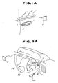
- Fig. 1A is a perspective view showing a request switch of the first embodiment mounted on an outside door handle portion.
- Fig. 1B is a perspective view showing a keyboard assembly of the second embodiment mounted on the outside door handle portion.
- Fig. 2A is a perspective view showing an instrument panel having a key storing means and the request switch of the first embodiment in accordance with the invention.
- Fig. 2B is a perspective view showing the instrument panel having the key storing means and the keyboard assembly of the second embodiment in accordance with the invention.
- Fig. 3 is a sectional view illustrating the key storing means according to the invention.
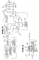
- Fig. 4 is a block diagram illustrating a control circuitry of vehicular devices of the first embodiment in accordance with the invention.
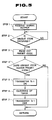
- Fig. 5 is a flow chart showing the order for releasing the key inserted into the key storing means through a radio signal from a portable transmitter.
- Fig. 6 is a block diagram illustrating a modification of the control circuitry of vehicular devices of the first embodiment shown in Fig. 4.
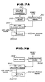
- Fig. 7A is a plan view illustrating an essential portion of a keyless entry system of the first embodiment according to the present invention.
- Fig. 7B is a plan view illustrating an essential portion of a keyless entry system of the second embodiment according to the present invention.
- Fig. 8 is a block diagram illustrating the control circuitry of the vehicular devices of the second embodiment according to the invention.
- Fig. 9 is a block diagram illustrating the modification of the control circuitry of the second embodiment shown in Fig. 8.
- Referring now to the drawings, particularly to Fig. 1A, a
request switch 2 which is a manually operable push-button-switch, is provided onouter door handle 1 and serves as an escutcheon trimming around akey cylinder 3. When the user pushes the request switch, transmitted is a unique identification code signal from a card type portablewireless transmitter 10. - In Fig. 2A, a locking
key holder assembly 32 for holding an ignition key is disposed near asteering cover 31 of a steering column. The lockingkey holder assembly 32 functions so as to lock or unlock the ignition key as clearly shown in Fig. 3. The lockingkey holder assembly 32 consists of akey receiving hole 321 for receiving the key, alock pin 322 actuable so as to project into thekey receiving hole 321, anactuator 323 for actuating thelock pin 322, and aLED segment 324 as an illumination source. - As shown in Fig. 4, the portable
wireless transmitter 10 includes anantenna 11 which is so designed as to transmit and receive radio signals to and from thetransmitter 10, amodem 12 which demodulates received request signals and generates output signals to be transmitted on the basis of the unique identification code, adetector 13 which detects the request signal demodulated in themodem 12, asignal generator 15 which derives the unique identification code from acode storage memory 14 and generates the unique identification code signal after detecting the request signal, and acarrier oscillator 16 for outputting a carrier signal during transmission of the unique identification signal through thetransmitter 10. - On the other hand, a
controller 20 provided in the vehicle, includes a pair ofdirectional antennas 21a and 21b each of which is designed to receive and transmit radio signals to and from thetransmitter 10 the directivity of said pair being at right angles to each other. The pair ofantennas 21a and 21b are formed in a door mirror. Further, thecontroller 20 includes amodem 22 which demodulates received signals and generates output signals to be transmitted to thetransmitter 10 on the basis of the request signal, acarrier oscillator 23 for outputting a carrier signal, aCPU 24 for wholly controlling a keyless entry system, acode storage memory 25 storing a preset identification code which is unique to the individual vehicle, atransistor Tr 1 which is turned on when a match between the unique identification code and the preset identification code is determined by the CPU, and arelay 26 excited by thetransistor Tr 1 turned on. Therelay 26 is connected to a plurality of vehicular devices, such as a coil 41c of an actuator for releasing a door lock provided in the driver seat side, acoil 42c of an actuator for releasing a door lock provided in the assistant seat side, acoil 323c of anactuator 323 for releasing thelock pin 322, and aLED segment 324 for illuminating the ignition key, respectively. Therefore, when therelay 26 is energized, the door locks are released and thelock pin 322 disappears from the insertinghole 321 of the ignition key and theLED segment 324 is activated. As clearly seen in Fig. 4, the input terminal of theCPU 24 is connected to therequest switch 2. Reference numeral R1 is a pull-up resistance provided so that theCPU 24 can discriminate the trailing edge of the input signal caused when therequest switch 2 is turned on. - The operation of the keyless entry system of the first embodiment will be described in detail in accordance with the procedure shown in Fig. 5:
- First, the
request switch 2 is operated; - In
Step 1, the request signal is transmitted from theantennas 21a and 21b to theantenna 11 of theportable wireless transmitter 10. - In
Step 2, the request signal is received by theantenna 11 of theportable transmitter 10 and thus the request signal is detected by thedetector 13 and simultaneously the unique identification code is read from thecode memory 14 to thecode signal generator 15. The unique code signal is outputted from thecode signal generator 15 to themodem 12. After this, themodem 12 receives a carrier wave which is generated by thecarrier oscillator 16, and superimposes the unique code signal on the carrier wave to form a radio signal in which the unique identification code signal rides on the carrier wave. Thus, themodem 12 transmits the unique identification code via theantennas 11 to theantennas 21a and 21b. As soon as theantennas 21a and 21b receive the unique identification code signal, the procedure is advanced toStep 3. - In
Step 3, the preset identification code is read out from thecode memory 25 to theCPU 24. - In
Step 4, theCPU 24 collates the unique identification code signal from thetransmitter 10 through the pair ofantennas 21a and 21b with the preset identification code signal. When these identification code signals match with each other, the procedure is advanced to thenext Step 5 in which thetransistor Tr 1 is turned on. As a result, as set forth above, therelay 26 is excited, the electric current flows through thecoils LED segment 324. As a result, the door lock is released and thelock pin 322 is retracted from thekey receiving hole 321 and then theLED segment 324 emits light. In this condition, the ignition key plate can be pulled out. - In
Step 6, a timer is activated and counts a predetermined time, for example, approximately 30 sec. - In
Step 7, thetransistor Tr 1 is turned off by the timer as soon as the predetermined time has elapsed. Thereafter, the aforementioned actuators and theLED segment 324 are deactivated. If inStep 4, theCPU 24 determines that the identification codes do not match, the process returns to the initial step. - The sequential operation of the keyless entry system according to first embodiment is as follows:
- In getting into a vehicle, upon operation of the
request switch 2 provided near theouter door handle 1 by the user carrying theportable transmitter card 10, the unique identification code is compared with the preset identification code of thecontroller 20 in the vehicle. If these identification codes match each other, the door locks are released and thelock pin 322 is retracted from thekey receiving hole 321 in the lockingkey holder assembly 32 disposed in the instrument panel and simultaneously theLED segment 324 emits light for lighting the key hole of locking key holder assembly. The ignition key in the receivinghole 321 may then be pulled out. Thereafter, the steering lock can be released and the engine starter can be driven, by rotating the ignition key inserted into the key cylinder. On the other hand, since the timer is activated on releasing the door locks, thetransistor Tr 1 is turned on after the predetermined time has elapsed. As a result, the doors are locked and thekey lock pin 322 projects again into the receivinghole 321 and theLED segment 324 turns off. Conversely, in getting out of a vehicle, after the engine is turned off and the steering is locked by rotating the ignition key, the key is pulled out of the key cylinder. When the key plate is inserted into the receivinghole 321, thelock pin 322 is pushed upward by the key. As thelock pin 322 is normally biased in such a manner that the pin projects into thekey receiving hole 321, the lock pin is finally biased into a circular opening bored in the center portion of the key plate and thus the ignition key is locked into the lockingkey holder assembly 32. - The modification of the first embodiment of the invention will be described hereinbelow.
- As shown in Fig. 2A, this modification features an another
request switch 51 in addition to therequest switch 2 shown in Fig. 1A and an anotherantenna 21c provided in the vehicular cabin. Therefore, the user may operate therequest switch 51 while seated in the driver's seat, whereafter the ignition key can be easily pulled out or inserted into the lockingkey holder assembly 32 in the vehicular cabin. Therequest switch 51 is disposed in the instrument panel. Theantenna 21c is built in thesteering handle 52. - As shown in Fig. 6, the
request switch 51 is connected to the input terminal of theCPU 24. Theantenna 21c is also connected to themodem 22. Further, the bases of twotransistors Tr 11 andTr 12 are connected to the respective output terminals of theCPU 24. Onetransistor Tr 11 is provided to release the door locks. Theother transistor Tr 12 is provided to release thelock pin 322. The collector oftransistor Tr 11 is connected to an exciting coil of arelay 27 through which the collector is connected to a collector bias supply Vcc. The emitter oftransistor Tr 11 is grounded. One end of thecoils 41c and 42c of actuators for releasing the door locks is connected to the collector bias supply Vcc and the other end is grounded through therelay 27. Therefore, whentransistor Tr 11 is turned on, the coil of therelay 27 is excited and electric current flows through thecoils 41c and 42c and the door locks are released. On the other hand, the collector oftransistor Tr 12 is connected to an exciting coil of arelay 28 through which the collector is connected to the collector bias supply Vcc. The emitter oftransistor Tr 11 is grounded. One lead of thecoil 323c of actuator for releasing the key lock pin and theLED segment 324 are connected to the collector bias supply Vcc and the other leads are grounded through therelay 28. Therefore, whentransistor Tr 12 is turned on, the coil of therelay 28 is excited and electric current flows through thecoil 323c and theLED segment 324. As will be appreciated from the above, in the modification of the first embodiment of the invention, the door locks are released by operating thefirst request switch 2 and subsequently thekey lock pin 322 is released and theLED segment 324 emits light by operating thesecond request switch 51. Thus, the operation of the modification of first embodiment is different from that of the first embodiment in that the first request switch operates only the door locks and the second request switch operates only the actuator for releasing the key lock pin and LED segment. - As shown in Fig. 7A, the keyless entry system of the first embodiment according to the invention will operate as follows:
- The unique identification code signal from a card-type portable wireless transmitter 100 outputs to a receiving means 200;
- Next, a discriminating means 300 collates the unique identification signal with the preset identification signal;
- When the unique identification signal matches the preset identification signal, the discriminating means 300 outputs an output signal and a key
lock releasing means 800 is operated and a key lock means 700 is released. As a result, anignition key 500 can be pulled out of a key storing means 600. In this manner, theignition key 500 can be safely kept in the key storing means 600. Therefore, the user is freed from the necessity of carrying the key. - The same reference numerals used in the first embodiment will be applied to the corresponding elements used in the second embodiment for the purpose of comparison between the first and second embodiments.
- As shown in Fig. 1B, the second embodiment is different from the first embodiment in that input keyboard switches 1a to 1e are provided on the
outer door handle 1 by which the unique identification code is manually inputted by the authorized user. The input keyboard switches 1a to 1e are identified as numerals (1,2), (3,4), (5,6), (7,8), and (9,0), respectively. A unique identification code comprised of five figure number for example may be inputted by the operation of the five keyboard switches. - As shown in Fig. 2B, the locking
key holder assembly 32 is the same as that shown in Figs. 2A and 3. - Fig. 8 illustrates a
controller 70 of a keyless entry system including a plurality of keyboard switches 1a, 1b, 1c, 1d, and 1e for inputting the unique identification code, a binary coded decimal convertor (BCD convertor) 72 for converting outputted signals generated by the operation of keyboard switches into binary coded decimals, anOR-gate circuit 73 for producting a logical sum of the input signals from theBCD convertor 72, anaddress counter 74 for outputting address signals of "1" to "5" in response to the output signals from theBCD convertor 72, and amemory 75 consisting of a programmable read only memory (PROM) or a random access memory (RAM). Further, thecontroller 70 comprises acomparator 76 which compares each output signal representative of figures from theBCD convertor 72 with each output signal representative of figures from thememory 75 and then outputs a high-level logic signal when the output signal from the BCD convertor matches with the output from the output signal from the memory, aquinary counter 77 which counts the high-level logic signal from thecomparator 76 for each figure number and outputs a high-level logic signal when the count reaches "5", a RS flip-flop circuit 78 which is set by the output signal supplied from thequinary counter 77 and outputs a coincidence signal for a predetermined time.Transistor 79 is then turned on and simultaneously atimer 80 starts clocking in accordance with the output signal from the flip-flop circuit 78. As soon as the elapse of the predetermined time is determined by thetimer 80, a oneshot multi-vibrator 31 is triggered and the RS flip-flop is reset with the result that thetransistor 79 is turned off. - Furthermore, the
controller 70 includes aretrigger multi-vibrator 82 which is triggered in response to the output signal of the OR-gate 73 and a one-shot multi-vibrator 83 which outputs a pulse signal for the predetermined time on the trailing edge of output signal of theretrigger multi-vibrator 82. The one-shot multi-vibrator 83 resets thequinary counter 77 through the OR-gate 73 when the predetermined time has elapsed. Moreover, thecontroller 70 includes anAND-gate circuit 85 which generates a logical product, adelay circuit 86 which delays the output signal of the AND-gate 85 for the predetermined time, and an OR-gate 84 which generates a logical sum from the output of the one-shot multi-vibrator 83 and the output of thedelay circuit 86. In this construction, when theaddress counter 74 outputs an address signal indicative of the binary numeral "101" which corresponds to a decimal "5", the AND-gate 85 outputs a high-level logic signal. The high-level logic signal goes to thedelay circuit 86 and goes to the OR-gate 84 after the elapse of the predetermined time. The output signal from the OR-gate 84 resets thequinary counter 77. - When the
transistor 79 is turned on in response to the output signal from the RS flip-flop circuit 78, electric current flows into thecoils LED segment 324 through arelay 87. In this manner, door lock actuators and key lock pin actuator is activated and the LED segment emits a light. As clearly seen in Figs. 8 and 4, the activating circuit of the coils and LED illustrated in Fig. 8 is the same as that illustrated in Fig. 4. - The sequential operation of the keyless entry system according to second embodiment is as follows:
- In getting into the vehicle, when the user operates the input keyboard switches 1a to 1e provided near the
outer door handle 1 according to the predetermined unique identification code, the output signals from the switches are converted into a binary coded decimal by theBCD convertor 72 and then sent to thecomparator 76 and also through the OR-gate 73 to theaddress counter 74. Theaddress counter 74 takes one step at every operation of the keyboard switch. Therefore, since theaddress counter 74 outputs an address signal "1" to thememory 75 in response to the first operation of input keyboard switch, the preset identification code stored in the first address of thememory 75 is outputted to thecomparator 76. In this way, thecomparator 76 compares the unique identification code signal from theBCD convertor 72 with the preset identification code signal from thememory 75 for every numeral of the identification code. If the unique code matches with the preset code, thecomparator 76 outputs a binary signal "1". Thequinary counter 77 counts these binary signal fromcomparator 76. If the unique code inputted from keyboard switch matches with the preset code from thememory 75 five times, thecomparator 76 outputs the binary signal "1" five times, and thequinary counter 77 outputs a coincidence signal to the RS flip-flop circuit 78 after counting the binary signal "1" five times. On the basis of this coincidence signal, the RS flip-flop 78 is set. As a result, the flip-flop 78 outputs a high-level signal through its Q terminal to the base of thetransistor 79, and thetransistor 79 is turned on with the result that therelay 87 is excited and subsequently electric current flows into thecoils LED segment 324. After this, the door locks are released and the key lock pin is retracted from the key receiving hole and the LED segment is turned on. The doors are locked and the lock pin projects into the key receiving hole and the LED segment is put off, after thetimer 80 counting the predetermined time (approximately 30 sec). - When getting out of the vehicle, the operation of keyless entry system of the second embodiment shown in Fig. 8 is identical with that of the first keyless entry system shown in Fig. 4
- As will be appreciated from the above, the construction of the
controller 20 of the first embodiment is different from that of thecontroller 70 of the second embodiment, but the function of both keyless entry systems is entirely equal. - A modification of the second embodiment of the invention will be described hereinbelow.
- As shown in Fig. 2B, this modification comprises another input keyboard switches 61a to 61e disposed in the instrument panel in addition to the input keyboard switches 1a to 1e shown in Fig. 1B. Therefore, the user may operate the keyboard switches 61a to 61e in accordance with the unique identification code while seated in the driver's seat, so that the ignition key can be pulled out of the locking
key holder assembly 32 in the vehicular cabin. - As shown in Fig. 9, the keyboard switches 61a to 61e are connected to an
OR-gate circuit 63 which is connected to the S terminal of a RS flip-flop circuit 64. The flip-flop 64 is set by the output signal from the OR-gate. Further, the bases of twotransistors Transistor 81 functions to release the door locks.Transistor 82 functions to release thelock pin 322 and to activate theLED segment 324. The collectors oftransistors relays transistors respective coils 41c and 42c of actuators for releasing the door locks is connected to the collector bias supply Vcc and the other lead is grounded through therelay 67. On the other hand, one lead of thecoil 323c and theLED segment 324 respectively is connected to the collector bias supply Vcc and the other is grounded through therelay 68. - The two input terminals of the AND
gate 65 are also connected to the output terminal Q of the flip-flop 78 and the inverted output terminalQ of the flip-flop 64. On the other hand, the two input terminals of the AND-gate 66 are connected to the respective output terminals Q of the flip-flop circuits - When the the unique identification code matches with the preset identification code in response to the operation of the input keyboard switches 1a to 1e, the high-level signals are simultaneously outputted from the respective output terminals Q and
Q of the flip-flop transistor 81. Therefore, thetransistor 81 is turned on with the result that therelay 67 is magnetized and the door locks are released. On the other hand, one input terminal ofAND-gate 66 receives the low-level logical signal from the output terminal Q of the flip-flop 64. Therefore, the actuator ofkey lock pin 322 remains deactivated. - Next, when the user operates the input keyboard switches 61a to 61e while seated in the driver's seat and the unique identification code matches the preset identification code, the two input terminals of
AND-gate 66 receives the high-level logical signals from the respective output terminals Q of the flip-flop AND-gate 65 receives the low-level logical signal from the inverted output terminalQ of the flip-flop 64. As a result, only the AND-gate 66 outputs an output signal to thetransistor 82 with the result that thekey lock pin 322 retracts from thekey receiving hole 321 and theLED segment 324 emits light. - Thus, the modification of the second embodiment is different in that manual operation of input keyboard switches 1a to 1e unlocks only the doors and manual operation of input keyboard switches 61a to 61e unlocks only the locking key holder.
- As shown in Fig. 7B, the keyless entry system of the second embodiment according to the invention will operate as follows:
- The unique identification code from an input means 100B is output to a discriminating means 300B;
- Next, the discriminating means 300B collates the unique identification signal with the preset identification signal;
- The subsequent operation is equal to that shown in Fig. 7A.
- While the essential elements a single controller are shared by the respective terminals of the modified embodiments. The first and second request switches, or the first and second keyboard switches respectively may have mutually separate controllers.
- While the locking key holder assembly of the present embodiment is fixed in the instrument panel of vehicles, the key lock hole assembly may be slidable.
- Moreover, although the locking key holder assembly of the instant embodiment is fixed in the instrument panel, a mechanical key cylinder, such as an ignition key cylinder, a glove box key cylinder or the like may function as the locking key holder device. In such construction, when the locking key holder device is activated, the key may be removed from the mechanical key cylinder or be operated in the mechanical key cylinder.
- Although the present invention has been disclosed in terms of keyless entry systems for automobiles, it is not intended to limit the scope of the invention to such keyless entry systems. The invention may be embodied in other specific forms without departing from the spirit or essential characteristics thereof. Therefore, the invention should be understood in all respects as defined by the appended claims rather than by the foregoing description and all modifications which come within the meaning and range of equivalency of the claims are therefore intended to be embraced therein.
Claims (19)
input means (10) for inputting a unique identification code signal:
control means (20) having a code memory (25), said control means which, when said unique identification code signal matches with a preset identification code signal stored in said memory, outputs a coincidence signal;
locking key holder means (32) disposed in the vehicular cabin for safely keeping a key, said locking key holder means which, only when receiving said coincidence signal from said control means, allows the key to be operated or to be removed.
a portable transmitter (10);
receiving means (20) for receiving a unique identification code signal from said portable transmitter;
discriminating means (22-25) for discriminating said unique identification code signal from a preset identification code signal, said discriminating means outputting a coincidence signal when these identification codes match each other;
key storing means (321) disposed in the vehicular cabin for receiving a key;
key lock means (321) for locking said key in an internal space defined by said key storing means;
key lock releasing means (323) for unlocking said key lock means in response to said coincidence signal from said discriminating means.
a portable transmitter (10) for inputting a unique identification code signal;
control means (20) having a code memory, said control means which, when said unique identification code signal matches with a preset identification code signal stored in said memory, outputs a coincidence signal;
a request switch (2) connected to said control means so that said control means outputs a request signal to said transmitter only when said request switch is manually operated;
said portable transmitter transmitting said unique identification code signal in response to said request signal;
locking key holder means (32) disposed in the vehicular cabin for safely keeping a key, said locking key holder means which, only when receiving said coincidence signal from said control means, allows the key to be operated or to be removed.
input means (1a-1e; 61a-61e) for manually inputting a unique identification code signal;
discriminating means (22-25) for discriminating said unique identification code signal from a preset identification code signal, said discriminating means outputting a coincidence signal when these identification codes match each other;
key storing means (32) disposed in the vehicular cabin for receiving a key;
key lock means (322) for locking said key in an internal space defined by said key storing means;
key lock releasing means (323) for unlocking said key lock means in response to said coincidence signal from said discriminating means.
Applications Claiming Priority (4)
| Application Number | Priority Date | Filing Date | Title |
|---|---|---|---|
| JP62272395A JPH01116179A (en) | 1987-10-28 | 1987-10-28 | Keyless load actuator for car |
| JP272394/87 | 1987-10-28 | ||
| JP27239487A JP2574335B2 (en) | 1987-10-28 | 1987-10-28 | Keyless load actuator for vehicles |
| JP272395/87 | 1987-10-28 |
Publications (3)
| Publication Number | Publication Date |
|---|---|
| EP0314143A2 true EP0314143A2 (en) | 1989-05-03 |
| EP0314143A3 EP0314143A3 (en) | 1990-03-28 |
| EP0314143B1 EP0314143B1 (en) | 1993-12-15 |
Family
ID=26550177
Family Applications (1)
| Application Number | Title | Priority Date | Filing Date |
|---|---|---|---|
| EP88117945A Expired - Lifetime EP0314143B1 (en) | 1987-10-28 | 1988-10-27 | Keyless entry system for automotive vehicles, with locking device for the ignition key |
Country Status (3)
| Country | Link |
|---|---|
| US (1) | US4898010A (en) |
| EP (1) | EP0314143B1 (en) |
| DE (1) | DE3886348T2 (en) |
Cited By (17)
| Publication number | Priority date | Publication date | Assignee | Title |
|---|---|---|---|---|
| EP0521547A1 (en) * | 1991-07-01 | 1993-01-07 | Medardo Reggiani | Passive action antitheft device |
| EP0610902A2 (en) * | 1993-02-08 | 1994-08-17 | Winner International | Anti-theft device especially for motor vehicles |
| FR2726846A1 (en) * | 1994-11-14 | 1996-05-15 | Valeo Securite Habitacle | Opening and closing system for central locking of vehicle doors |
| EP0769434A1 (en) * | 1995-10-20 | 1997-04-23 | Renault | Steering locking apparatus |
| GB2308405A (en) * | 1995-12-21 | 1997-06-25 | Denso Corp | Anti-theft device |
| US5679984A (en) * | 1994-02-17 | 1997-10-21 | Rover Group Limited | Vehicle security system |
| EP0834841A2 (en) * | 1996-10-02 | 1998-04-08 | Identec Limited | Communication system for vehicles |
| FR2783222A1 (en) * | 1998-09-15 | 2000-03-17 | Siemens Automotive Sa | Starting and security assembly for motor vehicle, includes system to start and stop vehicle engine using bistable button formed in key support |
| WO2001042599A1 (en) * | 1999-12-10 | 2001-06-14 | Siemens Automotive S.A. | Device for locking in position a motor vehicle electronic key |
| FR2805399A1 (en) * | 2000-02-18 | 2001-08-24 | Valeo Electronique | Hands free car starting system with antenna steering wheel held and search unit attached and limited zone coverage finding identifier detected/starter motor. |
| FR2813910A1 (en) * | 2000-09-11 | 2002-03-15 | Siemens Automotive Sa | Electronic key for motor vehicle starter has support with stop to retain key during use of vehicle |
| FR2814416A1 (en) * | 2000-09-27 | 2002-03-29 | Valeo Securite Habitacle | IMPROVED ASSEMBLY FOR A MOTOR VEHICLE FOR EXCHANGING DATA, SOME OF WHICH ARE REPRESENTATIVE OF AT LEAST ONE AUTHORIZED VEHICLE USER |
| WO2002045030A1 (en) * | 2000-12-01 | 2002-06-06 | Valeo Electronique | Device for detecting presence of a user for motor vehicle |
| FR2841392A1 (en) * | 2002-06-24 | 2003-12-26 | Johnson Contr Automotive Elect | RADIO TRANSMISSION DEVICE HAVING A CENTRALIZED MANAGEMENT UNIT AND A PLURALITY OF REMOTE TRANSMISSION ANTENNAS |
| US8429095B1 (en) | 1995-03-10 | 2013-04-23 | Michael C. Ryan | Fluid delivery control nozzle |
| CN103942862A (en) * | 2014-04-11 | 2014-07-23 | 马要武 | Password key starting device |
| CN105015653A (en) * | 2015-07-07 | 2015-11-04 | 镇江港龙机电有限公司 | Key chip secondary locking mechanism anti-theft lock and locking method thereof |
Families Citing this family (50)
| Publication number | Priority date | Publication date | Assignee | Title |
|---|---|---|---|---|
| US5209089A (en) * | 1990-01-26 | 1993-05-11 | Nelson Linden D | Key holder |
| US5412378A (en) * | 1990-06-13 | 1995-05-02 | Clemens; Jon K. | Antitheft protection of devices |
| US5255547A (en) * | 1992-08-19 | 1993-10-26 | General Motors Corporation | Ignition lock with dual unlocking modes |
| DE4315758C1 (en) * | 1993-05-11 | 1994-10-06 | Carton Angela | Security system |
| DE19517728C2 (en) * | 1995-05-15 | 1998-12-03 | Keso Gmbh | Locking device |
| JP3124229B2 (en) * | 1996-06-28 | 2001-01-15 | 富士通株式会社 | Wireless base station in WLL system using PHS, operation method thereof, and interface converter |
| US6164219A (en) * | 1996-10-25 | 2000-12-26 | John Richard Green | Security vault |
| US5778805A (en) * | 1996-10-25 | 1998-07-14 | Green; John Richard | Vehicle security vault with electronic lock |
| US6031465A (en) * | 1998-04-16 | 2000-02-29 | Burgess; James P. | Keyless entry system for vehicles in particular |
| US7106171B1 (en) | 1998-04-16 | 2006-09-12 | Burgess James P | Keyless command system for vehicles and other applications |
| DE19839347C1 (en) * | 1998-08-28 | 1999-12-02 | Daimler Chrysler Ag | Ignition lock system for motor vehicle developed to enable reliable detection of manipulation of the system |
| US6084317A (en) * | 1998-12-10 | 2000-07-04 | Trw Inc. | Keyless access control system with wireless, induction-powered keypad module and methods |
| US6617961B1 (en) | 1999-11-15 | 2003-09-09 | Strattec Security Corporation | Security system for a vehicle and method of operating same |
| US20040240679A1 (en) * | 2000-03-07 | 2004-12-02 | Kennedy James D. | Public address system and method for an urban transit vehicle |
| DE10147031B4 (en) * | 2000-09-27 | 2012-11-29 | Marquardt Gmbh | Ignition lock for a motor vehicle |
| US6516640B2 (en) | 2000-12-05 | 2003-02-11 | Strattec Security Corporation | Steering column lock apparatus and method |
| US6571587B2 (en) * | 2001-01-09 | 2003-06-03 | Strattec Security Corporation | Steering column lock apparatus and method |
| US6854870B2 (en) * | 2001-06-30 | 2005-02-15 | Donnelly Corporation | Vehicle handle assembly |
| US20030216817A1 (en) * | 2002-05-16 | 2003-11-20 | Richard Pudney | Vehicle access system with sensor |
| JP4248214B2 (en) * | 2002-09-26 | 2009-04-02 | 本田技研工業株式会社 | Anti-theft device for motorcycles |
| JP2004278050A (en) * | 2003-03-13 | 2004-10-07 | Alps Electric Co Ltd | Passive keyless entry device and method |
| JP4195842B2 (en) * | 2003-07-28 | 2008-12-17 | 株式会社東海理化電機製作所 | Engine start / stop control system |
| US7140213B2 (en) * | 2004-02-21 | 2006-11-28 | Strattec Security Corporation | Steering column lock apparatus and method |
| US7911321B2 (en) * | 2004-10-26 | 2011-03-22 | Adac Plastics, Inc. | Keyless entry system incorporating concealable keypad |
| US7576631B1 (en) | 2004-10-26 | 2009-08-18 | Adac Plastics, Inc. | Vehicular keyless entry system incorporating textual representation of the vehicle or user of the vehicle |
| US20060266089A1 (en) * | 2005-05-26 | 2006-11-30 | Dimig Steven J | Hybrid key |
| US20070210600A1 (en) * | 2006-03-09 | 2007-09-13 | Young John S | Keyless entry pickup truck toolbox |
| US7592714B2 (en) * | 2006-05-09 | 2009-09-22 | Safe Stop International, Llc | Ignition bypass system |
| US7334441B1 (en) * | 2007-01-16 | 2008-02-26 | Lear Corporation | Electronic vehicle key and housing assembly |
| JP4971084B2 (en) * | 2007-09-12 | 2012-07-11 | 株式会社東海理化電機製作所 | Bullet key storage device |
| JP4971083B2 (en) * | 2007-09-12 | 2012-07-11 | 株式会社東海理化電機製作所 | Bullet key storage device |
| JP5038238B2 (en) * | 2008-06-12 | 2012-10-03 | 株式会社東海理化電機製作所 | Vehicle function restriction system |
| US11469789B2 (en) | 2008-07-09 | 2022-10-11 | Secureall Corporation | Methods and systems for comprehensive security-lockdown |
| US9642089B2 (en) | 2008-07-09 | 2017-05-02 | Secureall Corporation | Method and system for planar, multi-function, multi-power sourced, long battery life radio communication appliance |
| US10128893B2 (en) | 2008-07-09 | 2018-11-13 | Secureall Corporation | Method and system for planar, multi-function, multi-power sourced, long battery life radio communication appliance |
| US10447334B2 (en) | 2008-07-09 | 2019-10-15 | Secureall Corporation | Methods and systems for comprehensive security-lockdown |
| US8487743B2 (en) * | 2008-08-18 | 2013-07-16 | GM Global Technology Operations LLC | Valet keyfob system |
| JP5296470B2 (en) * | 2008-09-24 | 2013-09-25 | 株式会社東海理化電機製作所 | In-vehicle auxiliary key key holding device |
| JP5426857B2 (en) * | 2008-09-24 | 2014-02-26 | 株式会社東海理化電機製作所 | Key slot device for in-vehicle auxiliary key |
| US20100088855A1 (en) * | 2008-10-14 | 2010-04-15 | Magna Mirrors Of America, Inc. | Vehicle door handle assembly |
| KR100986462B1 (en) * | 2008-11-28 | 2010-10-08 | 기아자동차주식회사 | Key inter lock of automobile |
| US8482382B2 (en) * | 2009-03-12 | 2013-07-09 | Honda Motor Co., Ltd. | Systems and methods for controlling a smart communication system for a vehicle |
| US8786401B2 (en) | 2009-12-23 | 2014-07-22 | Magna Mirrors Of America, Inc. | Extendable flush door handle for vehicle |
| US8712648B2 (en) | 2011-03-08 | 2014-04-29 | Gm Global Technology Operations | Passive charge cord release system for an electric vehicle |
| US8690591B2 (en) | 2011-06-09 | 2014-04-08 | GM Global Technology Operations LLC | Electric vehicle with secondary charge cord release mechanism |
| CN102529888A (en) * | 2012-03-13 | 2012-07-04 | 鸿富锦精密工业(深圳)有限公司 | Automobile use permission control system and method |
| WO2013138791A1 (en) * | 2012-03-16 | 2013-09-19 | Secureall Corporation | Non-contact electronic door locks having specialized radio frequency beam formation |
| KR101856336B1 (en) * | 2016-07-14 | 2018-05-11 | 현대자동차주식회사 | Tray device for vehicle |
| FR3069943B1 (en) * | 2017-08-02 | 2020-10-02 | Valeo Comfort & Driving Assistance | HANDS-FREE ACCESS FOR MOTOR VEHICLES |
| CN113844406B (en) * | 2021-09-30 | 2023-09-22 | 重庆长安汽车股份有限公司 | Vehicle keyless starting method and system and vehicle |
Citations (4)
| Publication number | Priority date | Publication date | Assignee | Title |
|---|---|---|---|---|
| US3851505A (en) * | 1973-05-01 | 1974-12-03 | L Wilkinson | Card holder for vehicles |
| EP0088490A1 (en) * | 1982-02-15 | 1983-09-14 | Nissan Motor Co., Ltd. | Keyless device actuating system for an automotive vehicle |
| DE3627493A1 (en) * | 1986-08-13 | 1988-02-25 | Yannikos Sibylle | Key with a code |
| EP0158354B1 (en) * | 1984-04-12 | 1988-12-28 | Nissan Motor Co., Ltd. | Keyless entry system for automotive devices with compact, portable wireles code transmitter, and feature for preventing users from locking transmitter in vehicle |
Family Cites Families (7)
| Publication number | Priority date | Publication date | Assignee | Title |
|---|---|---|---|---|
| JPS519218B1 (en) * | 1969-11-24 | 1976-03-25 | ||
| JPS59185270A (en) * | 1983-04-05 | 1984-10-20 | 日産自動車株式会社 | Keyless load operation apparatus for vehicle |
| US4719460A (en) * | 1983-09-19 | 1988-01-12 | Nissan Motor Company, Limited | Keyless entry system for automotive vehicle devices with theft-prevention feature |
| US4672375A (en) * | 1983-11-29 | 1987-06-09 | Nissan Motor Company, Limited | Keyless entry system for automotive devices with compact, portable wireless code transmitter, and feature for preventing users from locking transmitter in vehicle |
| JPS61237777A (en) * | 1985-04-11 | 1986-10-23 | 日産自動車株式会社 | Key apparatus |
| US4641509A (en) * | 1985-10-16 | 1987-02-10 | Batchelor Ronnie K | Master keyboard |
| JPH0625503B2 (en) * | 1986-06-20 | 1994-04-06 | 日産自動車株式会社 | Unlock control device |
-
1988
- 1988-10-25 US US07/261,899 patent/US4898010A/en not_active Expired - Lifetime
- 1988-10-27 DE DE19883886348 patent/DE3886348T2/en not_active Expired - Fee Related
- 1988-10-27 EP EP88117945A patent/EP0314143B1/en not_active Expired - Lifetime
Patent Citations (4)
| Publication number | Priority date | Publication date | Assignee | Title |
|---|---|---|---|---|
| US3851505A (en) * | 1973-05-01 | 1974-12-03 | L Wilkinson | Card holder for vehicles |
| EP0088490A1 (en) * | 1982-02-15 | 1983-09-14 | Nissan Motor Co., Ltd. | Keyless device actuating system for an automotive vehicle |
| EP0158354B1 (en) * | 1984-04-12 | 1988-12-28 | Nissan Motor Co., Ltd. | Keyless entry system for automotive devices with compact, portable wireles code transmitter, and feature for preventing users from locking transmitter in vehicle |
| DE3627493A1 (en) * | 1986-08-13 | 1988-02-25 | Yannikos Sibylle | Key with a code |
Cited By (31)
| Publication number | Priority date | Publication date | Assignee | Title |
|---|---|---|---|---|
| US5280267A (en) * | 1991-07-01 | 1994-01-18 | Medardo Reggiani | Passive action antitheft device |
| EP0521547A1 (en) * | 1991-07-01 | 1993-01-07 | Medardo Reggiani | Passive action antitheft device |
| EP0610902A2 (en) * | 1993-02-08 | 1994-08-17 | Winner International | Anti-theft device especially for motor vehicles |
| EP0610902A3 (en) * | 1993-02-08 | 1995-07-05 | Winner Int | Anti-theft device especially for motor vehicles. |
| EP1380479A2 (en) * | 1993-02-08 | 2004-01-14 | Winner International Royalty LLC | Anti-theft device especially for motor vehicles |
| EP1380479A3 (en) * | 1993-02-08 | 2004-01-21 | Winner International Royalty LLC | Anti-theft device especially for motor vehicles |
| US5679984A (en) * | 1994-02-17 | 1997-10-21 | Rover Group Limited | Vehicle security system |
| FR2726846A1 (en) * | 1994-11-14 | 1996-05-15 | Valeo Securite Habitacle | Opening and closing system for central locking of vehicle doors |
| US8429095B1 (en) | 1995-03-10 | 2013-04-23 | Michael C. Ryan | Fluid delivery control nozzle |
| FR2740087A1 (en) * | 1995-10-20 | 1997-04-25 | Renault | STEERING COLUMN LOCKING DEVICE |
| EP0769434A1 (en) * | 1995-10-20 | 1997-04-23 | Renault | Steering locking apparatus |
| GB2308405B (en) * | 1995-12-21 | 1999-11-03 | Denso Corp | Anti-theft device having excellent identification code overwriting capabilities |
| US5982295A (en) * | 1995-12-21 | 1999-11-09 | Denso Corporation | Anti-theft device having excellent identification code overwriting capabilities |
| GB2308405A (en) * | 1995-12-21 | 1997-06-25 | Denso Corp | Anti-theft device |
| EP0834841A2 (en) * | 1996-10-02 | 1998-04-08 | Identec Limited | Communication system for vehicles |
| US6434983B1 (en) | 1998-09-15 | 2002-08-20 | Siemens Vdo Automotive S.A.S. | Starting and locking/unlocking device for motor vehicle |
| FR2783222A1 (en) * | 1998-09-15 | 2000-03-17 | Siemens Automotive Sa | Starting and security assembly for motor vehicle, includes system to start and stop vehicle engine using bistable button formed in key support |
| WO2000015476A1 (en) * | 1998-09-15 | 2000-03-23 | Siemens Automotive S.A. | Starting and locking/unlocking device for motor vehicle |
| WO2001042599A1 (en) * | 1999-12-10 | 2001-06-14 | Siemens Automotive S.A. | Device for locking in position a motor vehicle electronic key |
| FR2802235A1 (en) * | 1999-12-10 | 2001-06-15 | Siemens Automotive Sa | DEVICE FOR LOCKING THE POSITION OF AN ELECTRONIC KEY OF A MOTOR VEHICLE |
| FR2805399A1 (en) * | 2000-02-18 | 2001-08-24 | Valeo Electronique | Hands free car starting system with antenna steering wheel held and search unit attached and limited zone coverage finding identifier detected/starter motor. |
| FR2813910A1 (en) * | 2000-09-11 | 2002-03-15 | Siemens Automotive Sa | Electronic key for motor vehicle starter has support with stop to retain key during use of vehicle |
| EP1193145A1 (en) * | 2000-09-27 | 2002-04-03 | Valeo Securité Habitacle | Device for exchanging data, some of which is representative of at least one authorized user of an automotive vehicle |
| FR2814416A1 (en) * | 2000-09-27 | 2002-03-29 | Valeo Securite Habitacle | IMPROVED ASSEMBLY FOR A MOTOR VEHICLE FOR EXCHANGING DATA, SOME OF WHICH ARE REPRESENTATIVE OF AT LEAST ONE AUTHORIZED VEHICLE USER |
| WO2002045030A1 (en) * | 2000-12-01 | 2002-06-06 | Valeo Electronique | Device for detecting presence of a user for motor vehicle |
| US7190089B2 (en) | 2000-12-01 | 2007-03-13 | Valeo Electronique | Device for detecting presence of a user for motor vehicle |
| WO2004001681A1 (en) * | 2002-06-24 | 2003-12-31 | Johnson Controls Technology Company | Radio transmission device having a centralized management unit and a plurality of remote transmission antennae |
| FR2841392A1 (en) * | 2002-06-24 | 2003-12-26 | Johnson Contr Automotive Elect | RADIO TRANSMISSION DEVICE HAVING A CENTRALIZED MANAGEMENT UNIT AND A PLURALITY OF REMOTE TRANSMISSION ANTENNAS |
| CN103942862A (en) * | 2014-04-11 | 2014-07-23 | 马要武 | Password key starting device |
| WO2015154699A1 (en) * | 2014-04-11 | 2015-10-15 | 马要武 | Vehicle key apparatus |
| CN105015653A (en) * | 2015-07-07 | 2015-11-04 | 镇江港龙机电有限公司 | Key chip secondary locking mechanism anti-theft lock and locking method thereof |
Also Published As
| Publication number | Publication date |
|---|---|
| DE3886348T2 (en) | 1994-06-30 |
| EP0314143A3 (en) | 1990-03-28 |
| DE3886348D1 (en) | 1994-01-27 |
| US4898010A (en) | 1990-02-06 |
| EP0314143B1 (en) | 1993-12-15 |
Similar Documents
| Publication | Publication Date | Title |
|---|---|---|
| US4898010A (en) | Keyless entry system for automotive vehicles | |
| US4670746A (en) | Keyless entry system for automotive devices with feature for giving caution for locking wireless code transmitter in vehicle | |
| US5113182A (en) | Vehicle door locking system detecting that all doors are closed | |
| US5864297A (en) | Reprogrammable remote keyless entry system | |
| US4652860A (en) | Security installation | |
| US5109221A (en) | Remote control system for door locks | |
| US5252966A (en) | Transmitter for remote control system for door locks | |
| US5736935A (en) | Keyless vehicle entry and engine starting system | |
| EP1659543B1 (en) | Security system and portable device usable therein | |
| US4719460A (en) | Keyless entry system for automotive vehicle devices with theft-prevention feature | |
| US4881148A (en) | Remote control system for door locks | |
| US6724322B2 (en) | Remote system for providing vehicle information to a user | |
| US7511602B2 (en) | Keyless entry module and method | |
| KR100248458B1 (en) | Portable transceiver for keyless vehicle entry system having phase delay | |
| JP3142508B2 (en) | Vehicle electronic key device | |
| EP0292217A2 (en) | Remote control system for door locks | |
| EP1090198B1 (en) | Remote control transmitter broadcasting rf signals conveying plural information components | |
| US6335576B1 (en) | Remote keyless entry receiver having correctly matched transmitters | |
| KR100608224B1 (en) | Personal identification card system for controlling vehicles | |
| US5969596A (en) | Security system with automatic door locking/unlocking function | |
| JP2001130381A (en) | Electronic key device for vehicle | |
| EP0084352B1 (en) | Electronic door locking system for an automotive vehicle | |
| US6480095B1 (en) | Vehicle control system including multi-digit control switch and associated methods | |
| JP3667272B2 (en) | Smart entry system for vehicle and control method thereof | |
| JP2001115707A (en) | Smart entry system for vehicle and its control method |
Legal Events
| Date | Code | Title | Description |
|---|---|---|---|
| PUAI | Public reference made under article 153(3) epc to a published international application that has entered the european phase |
Free format text: ORIGINAL CODE: 0009012 |
|
| 17P | Request for examination filed |
Effective date: 19881027 |
|
| AK | Designated contracting states |
Kind code of ref document: A2 Designated state(s): DE GB |
|
| PUAL | Search report despatched |
Free format text: ORIGINAL CODE: 0009013 |
|
| AK | Designated contracting states |
Kind code of ref document: A3 Designated state(s): DE GB |
|
| 17Q | First examination report despatched |
Effective date: 19920602 |
|
| GRAA | (expected) grant |
Free format text: ORIGINAL CODE: 0009210 |
|
| AK | Designated contracting states |
Kind code of ref document: B1 Designated state(s): DE GB |
|
| REF | Corresponds to: |
Ref document number: 3886348 Country of ref document: DE Date of ref document: 19940127 |
|
| PLBE | No opposition filed within time limit |
Free format text: ORIGINAL CODE: 0009261 |
|
| STAA | Information on the status of an ep patent application or granted ep patent |
Free format text: STATUS: NO OPPOSITION FILED WITHIN TIME LIMIT |
|
| 26N | No opposition filed | ||
| REG | Reference to a national code |
Ref country code: GB Ref legal event code: IF02 |
|
| PGFP | Annual fee paid to national office [announced via postgrant information from national office to epo] |
Ref country code: DE Payment date: 20051020 Year of fee payment: 18 |
|
| PGFP | Annual fee paid to national office [announced via postgrant information from national office to epo] |
Ref country code: GB Payment date: 20051026 Year of fee payment: 18 |
|
| PG25 | Lapsed in a contracting state [announced via postgrant information from national office to epo] |
Ref country code: DE Free format text: LAPSE BECAUSE OF NON-PAYMENT OF DUE FEES Effective date: 20070501 |
|
| GBPC | Gb: european patent ceased through non-payment of renewal fee |
Effective date: 20061027 |
|
| PG25 | Lapsed in a contracting state [announced via postgrant information from national office to epo] |
Ref country code: GB Free format text: LAPSE BECAUSE OF NON-PAYMENT OF DUE FEES Effective date: 20061027 |