EP0309458B1 - Flame incubating and propagating apparatus for a fuel combustion system - Google Patents
Flame incubating and propagating apparatus for a fuel combustion system Download PDFInfo
- Publication number
- EP0309458B1 EP0309458B1 EP87903175A EP87903175A EP0309458B1 EP 0309458 B1 EP0309458 B1 EP 0309458B1 EP 87903175 A EP87903175 A EP 87903175A EP 87903175 A EP87903175 A EP 87903175A EP 0309458 B1 EP0309458 B1 EP 0309458B1
- Authority
- EP
- European Patent Office
- Prior art keywords
- fuel
- baffle
- ignition
- combustion chamber
- flame
- Prior art date
- Legal status (The legal status is an assumption and is not a legal conclusion. Google has not performed a legal analysis and makes no representation as to the accuracy of the status listed.)
- Expired - Lifetime
Links
Images


Classifications
-
- F—MECHANICAL ENGINEERING; LIGHTING; HEATING; WEAPONS; BLASTING
- F02—COMBUSTION ENGINES; HOT-GAS OR COMBUSTION-PRODUCT ENGINE PLANTS
- F02B—INTERNAL-COMBUSTION PISTON ENGINES; COMBUSTION ENGINES IN GENERAL
- F02B23/00—Other engines characterised by special shape or construction of combustion chambers to improve operation
- F02B23/08—Other engines characterised by special shape or construction of combustion chambers to improve operation with positive ignition
- F02B23/10—Other engines characterised by special shape or construction of combustion chambers to improve operation with positive ignition with separate admission of air and fuel into cylinder
- F02B23/101—Other engines characterised by special shape or construction of combustion chambers to improve operation with positive ignition with separate admission of air and fuel into cylinder the injector being placed on or close to the cylinder centre axis, e.g. with mixture formation using spray guided concepts
-
- F—MECHANICAL ENGINEERING; LIGHTING; HEATING; WEAPONS; BLASTING
- F02—COMBUSTION ENGINES; HOT-GAS OR COMBUSTION-PRODUCT ENGINE PLANTS
- F02B—INTERNAL-COMBUSTION PISTON ENGINES; COMBUSTION ENGINES IN GENERAL
- F02B23/00—Other engines characterised by special shape or construction of combustion chambers to improve operation
- F02B23/02—Other engines characterised by special shape or construction of combustion chambers to improve operation with compression ignition
- F02B23/06—Other engines characterised by special shape or construction of combustion chambers to improve operation with compression ignition the combustion space being arranged in working piston
- F02B23/0645—Details related to the fuel injector or the fuel spray
- F02B23/0654—Thermal treatments, e.g. with heating elements or local cooling
- F02B23/0657—Thermal treatments, e.g. with heating elements or local cooling the spray interacting with one or more glow plugs
-
- F—MECHANICAL ENGINEERING; LIGHTING; HEATING; WEAPONS; BLASTING
- F02—COMBUSTION ENGINES; HOT-GAS OR COMBUSTION-PRODUCT ENGINE PLANTS
- F02B—INTERNAL-COMBUSTION PISTON ENGINES; COMBUSTION ENGINES IN GENERAL
- F02B23/00—Other engines characterised by special shape or construction of combustion chambers to improve operation
- F02B23/02—Other engines characterised by special shape or construction of combustion chambers to improve operation with compression ignition
- F02B23/06—Other engines characterised by special shape or construction of combustion chambers to improve operation with compression ignition the combustion space being arranged in working piston
- F02B23/0696—W-piston bowl, i.e. the combustion space having a central projection pointing towards the cylinder head and the surrounding wall being inclined towards the cylinder wall
-
- F—MECHANICAL ENGINEERING; LIGHTING; HEATING; WEAPONS; BLASTING
- F02—COMBUSTION ENGINES; HOT-GAS OR COMBUSTION-PRODUCT ENGINE PLANTS
- F02B—INTERNAL-COMBUSTION PISTON ENGINES; COMBUSTION ENGINES IN GENERAL
- F02B23/00—Other engines characterised by special shape or construction of combustion chambers to improve operation
- F02B23/08—Other engines characterised by special shape or construction of combustion chambers to improve operation with positive ignition
- F02B23/10—Other engines characterised by special shape or construction of combustion chambers to improve operation with positive ignition with separate admission of air and fuel into cylinder
- F02B2023/103—Other engines characterised by special shape or construction of combustion chambers to improve operation with positive ignition with separate admission of air and fuel into cylinder the injector having a multi-hole nozzle for generating multiple sprays
-
- F—MECHANICAL ENGINEERING; LIGHTING; HEATING; WEAPONS; BLASTING
- F02—COMBUSTION ENGINES; HOT-GAS OR COMBUSTION-PRODUCT ENGINE PLANTS
- F02B—INTERNAL-COMBUSTION PISTON ENGINES; COMBUSTION ENGINES IN GENERAL
- F02B23/00—Other engines characterised by special shape or construction of combustion chambers to improve operation
- F02B23/08—Other engines characterised by special shape or construction of combustion chambers to improve operation with positive ignition
- F02B23/10—Other engines characterised by special shape or construction of combustion chambers to improve operation with positive ignition with separate admission of air and fuel into cylinder
- F02B2023/108—Swirl flow, i.e. the axis of rotation of the main charge flow motion is vertical
-
- F—MECHANICAL ENGINEERING; LIGHTING; HEATING; WEAPONS; BLASTING
- F02—COMBUSTION ENGINES; HOT-GAS OR COMBUSTION-PRODUCT ENGINE PLANTS
- F02B—INTERNAL-COMBUSTION PISTON ENGINES; COMBUSTION ENGINES IN GENERAL
- F02B75/00—Other engines
- F02B75/12—Other methods of operation
- F02B2075/125—Direct injection in the combustion chamber for spark ignition engines, i.e. not in pre-combustion chamber
-
- F—MECHANICAL ENGINEERING; LIGHTING; HEATING; WEAPONS; BLASTING
- F02—COMBUSTION ENGINES; HOT-GAS OR COMBUSTION-PRODUCT ENGINE PLANTS
- F02B—INTERNAL-COMBUSTION PISTON ENGINES; COMBUSTION ENGINES IN GENERAL
- F02B2275/00—Other engines, components or details, not provided for in other groups of this subclass
- F02B2275/14—Direct injection into combustion chamber
-
- F—MECHANICAL ENGINEERING; LIGHTING; HEATING; WEAPONS; BLASTING
- F05—INDEXING SCHEMES RELATING TO ENGINES OR PUMPS IN VARIOUS SUBCLASSES OF CLASSES F01-F04
- F05C—INDEXING SCHEME RELATING TO MATERIALS, MATERIAL PROPERTIES OR MATERIAL CHARACTERISTICS FOR MACHINES, ENGINES OR PUMPS OTHER THAN NON-POSITIVE-DISPLACEMENT MACHINES OR ENGINES
- F05C2201/00—Metals
- F05C2201/04—Heavy metals
- F05C2201/0433—Iron group; Ferrous alloys, e.g. steel
- F05C2201/0448—Steel
- F05C2201/046—Stainless steel or inox, e.g. 18-8
-
- Y—GENERAL TAGGING OF NEW TECHNOLOGICAL DEVELOPMENTS; GENERAL TAGGING OF CROSS-SECTIONAL TECHNOLOGIES SPANNING OVER SEVERAL SECTIONS OF THE IPC; TECHNICAL SUBJECTS COVERED BY FORMER USPC CROSS-REFERENCE ART COLLECTIONS [XRACs] AND DIGESTS
- Y02—TECHNOLOGIES OR APPLICATIONS FOR MITIGATION OR ADAPTATION AGAINST CLIMATE CHANGE
- Y02T—CLIMATE CHANGE MITIGATION TECHNOLOGIES RELATED TO TRANSPORTATION
- Y02T10/00—Road transport of goods or passengers
- Y02T10/10—Internal combustion engine [ICE] based vehicles
- Y02T10/12—Improving ICE efficiencies
Definitions
- This invention relates to a fuel combustion system in a direct-injection internal combustion engine and, more particularly, to such a fuel combustion system adapted to efficiently ignite and burn non-autoignitable fuels such as ethanol or methanol as well as autoignitable fuels such as traditional diesel fuel.
- these alternative fuels are characterized by a cetane number of ignition value on the order of about 0-10 whereas traditional diesel fuels, such as Grade 2-D diesel fuel, are characterized by a cetane number of at least 40. Consequently, unlike traditional diesel fuels, these relatively lower-cetane-number alternative fuels do not readily autoignite under normal compression ratios and temperatures of about 538°C (1000°F), in an open combustion chamber of a compression-ignition engine, merely by contacting and mixing with intake air which has been compressed and thereby heated by a piston.
- Such relatively lower-cetane-number alternative fuels can be locally ignited with the aid of an electrically-energized glow plug or spark plug which directly heats a nearby air/fuel mixture to a sufficiently elevated temperature of about 1000°C (1832°F).
- an electrically-energized glow plug or spark plug which directly heats a nearby air/fuel mixture to a sufficiently elevated temperature of about 1000°C (1832°F).
- another major problem exists of completely igniting and burning all of the alternative fuel that is directly injected into the open combustion chamber. This problem is due to the way fuel has been typically directly injected into the open combustion chamber of a modern compression-ignition engine.
- a conventional open combustion chamber of a direct-injection compression-ignition engine typically includes a relatively high-pressure fuel injector having a plurality of very small fuel spray orifices. These orifices periodically and simultaneously spray a plurality of distinct and evenly spaced high pressure fuel streams towards various peripheral portions of the open combustion chamber which is already filled with fresh intake air.
- This pattern of relatively concentrated conical fuel streams separated by sectors of fuel-deficient intake air, similar to the radial spokes of a wheel, is desirable for modern direct-injection engines to provide each fuel stream without enough kinetic energy so that it can quickly and adequately penetrate, atomize, mix, and combust with the required larger amounts of intake air before each cyclic power stroke of the open combustion chamber has substantially begun.
- a glow plug or sprak plug is electrically-energized to produce a localized elevated temperature of about 1000°C (1832°F) and is positioned in close enough proximity to one of the mutually-spaced fuel streams of relatively lower-cetane-number alternative fuel, usually only that one fuel stream and other sufficiently close fuel streams will ignite.
- the fuel-deficient sectors of air separating each of the other remotely spaced fuel streams will prevent the flame from propagating to those other fuel streams. Consequently, the fuel streams which are not ignited, or are only partially burned, are exhausted from the open combustion chamber as either wasted raw fuel or incompletely combusted fuel.
- a fuel combustion system including a multiple-orifice fuel injector, a fuel ignition-initiating means, a secondary fuel spray orifice, and an impingement surface element having a deflecting face spaced from the facing that secondary orifice.
- this arrangement effectively generates an auxiliary cloud of atomized fuel which interconnectedly bridges other mutually-spaced fuel streams so a flame can be rapidly propagated without depending on the existence of swirling gas flow.
- non-oxygenated fuels such as diesel fuel or unleaded gasoline, respectivey.
- the size of the secondary orifice is usually chosen in accordance with ensuring satisfactory engine operation at light engine loads and therefor the size of the secondary orifice may be somewhat too large for spraying non-oxygenated fuels when the engine is operated at heavy loads. Consequently, at heavy engine loads, too much non-oxygenated fuel may be sprayed through the secondary orifice such that the fuel is unable adequately to mix and combust with air. Furthermore, the above arrangement may require special modifications to standard off-the-shelf fuel injectors and/or pistons which add to the cost of the engine.
- DE-A-1 804 383 discloses a direct-injection internal combustion engine having a fuel combustion system which includes a combustion chamber; a plurality of fuel spray orifices each having a centreline axis directed outwardly into the combustion chamber; a fuel ignition-initiating means projecting directly into the combustion chamber and spaced a distance from at least one of the fuel spray orifices and also spaced from the centreline axis of this one fuel spray orifice; baffle means to intercept a portion of the fuel stream sprayed from the one spray orifice during engine operation, so that the intercepted fuel flows onto a surface of the baffle means, the surface facing the place where an initially localized flame of burning fuel is started by the fuel ignition-initiating means; and, according to the invention, such an engine is characterised in that the surface provides a line of sight to all the other fuel streams thereby controllably directing the resulting expanding flame of burning fuel to all of the other fuel streams sprayed from the other fuel spray orifices.
- the baffle means helps start a localized flame of burning fuel and then controlledly directs the resultant expanding flame of burning fuel to all of the other fuel streams sprayed from the fuel injector so that they are interconnectedly bridged with the flame and thereby positively ignited, to ensure complete and rapid combustion during each relatively brief combustion stroke.
- the baffle means also helps prevent fuel or gases from undesirably cooling the fuel ignition-initiating means during engine operation.
- an improved fuel combustion system 10 is shown as incorporated in a direct-injection internal combustion engine 14 (Fig. 1).
- the engine 14 may have originally been a conventional compression-ignition engine which has been inexpensively and easily modified as described below.
- the fuel combustion system 10 includes an open combustion chamber 18; only a single fuel injector 22; a fuel ignition-initiating means or device 26 for initiating localized ignition and flaming of fuel injected into the open combustion chamber 18; and a unique baffle means 30 for intercepting a preselected portion 34, 38 (Fig.
- the open combustion chamber 18 incorporates no flow restrictions that are sufficiently small to cause large differences in gas pressure between the different parts of the open combustion chamber during the combustion process.
- the open combustion chamber 18 is defined mainly by, for example, a conventional Mexican-hat-shaped crater wall 46 (Fig. 1) of an axially-reciprocable piston 50, shown at about the top dead center position of its periodic compression stroke, a stationary cylinder liner 54 having a cylindrical bore 58 in which the piston 50 reciprocates, and a bottom deck 62 of a cylinder head 66 which clamps the cylinder liner 54 to an engine block 70.
- the open combustion chamber 18 is of the quiescent type so that the motion of gases therein is substantially random instead of being unidirectional or otherwise ordered.
- the quiescent type of open combustion chamber is preferably chosen because it provides a minimal level of turbulence and heat transfer which helps achieve low specific fuel consumption.
- the reference numbers 74 in Fig. 3 indicate fresh intake air which is periodically admitted into the open combustion chamber by one of more intake poppet valves 78 and, following combustion, is discharged by one or more exhaust poppet valves 80.
- the fuel injector 22 may be, for example, a conventional fuel injection nozzle or a unit fuel pump injector and includes an elongated injector body 82 (Figs. 1-2) extending through a bore in the cylinder head 66.
- the fuel injector 22 may be accurately secured to the cylinder head 66, for example, by a clamping arrangement as described in US-A-4,206,725.
- Connected to one end portion of the injector body 82 is a partly semi-spherical nozzle tip 86 (Figs. 1-3) which preferably projects directly into a central portion of the open combustion chamber 18.
- the nozzle tip 86 includes a plurality of evenly spaced fuel spray orifices 90, 94, 98 (Fig. 3), positioned circumferentially in a common horizontal plane, which are adapted during engine operation to simultaneously spray distinct and evenly spaced conical fuel streams 102, 106, 110 generally radially outwardly towards outer peripheral portions of the open combustion chamber 18.
- the plurality of fuel spray orifices preferably total at least five and, for example, total nine evenly-space fuel spray orifices in Fig. 3.
- each of the fuel streams 102,106, 110 has an imaginary centerline axis, coincident with the centerline axis of each respective fuel spray orifice, and all of the fuel streams are mutually separated by fuel-deficient sectors 74 of the intake air.
- the fuel ignition-initiating means 26 is shown, for example, as mainly including an elongated and electrically-energizable glow plug 114 which is directly and threadedly connected inside a generally cylindrical and hollow adapter 118 that is threadedly connected to or otherwise supported in another bore of the cylinder head 66.
- the adapter 118 extends completely through the cylinder head 66 and is seated against an annular seal 122 disposed in a counterbore 126 of the bottom deck 62.
- the adapter 118 and the seal 122 which, for example, may be made of stainless steel and copper- bronze alloy, respectively, function to protect the glow plug 114 from directly contacting liquid coolant which is circulated during engine operation through internal chambers 130 of the cylinder head 66.
- the cylinder head 66 may be provided with a cast-in or otherwise integral boss havig a bore directly through which the glow plug 114 extends to seat against the seal 122.
- an electrical resistance element 134 (Figs. 2-3) of, for example, circular or generally rectangular cross-section which also projects directly into the central portion of the open combustion chamber 18 so that it is unobstructively spaced a preselected distance L, (Fig. 3) from at least one, and preferably a pair of, selected fuel spray orifices 90,94 of the nozzle tip 86.
- the fuel ignition-initiating means 26 is positioned in spaced relation between the centerline axes of the pathways of the respective pair of adjacent fuel streams 102, 106 in order to avoid cooling of the electrical resistance element 134 and to avoid cracking of fuel caused by direct surface impingement thereon of the relatively dense portions of those fuel streams 102, 106.
- the fuel ignition-initiating means 26 may mainly include, instead of the glow plug 114, an electrically-energizable spark plug or some other high energy device which, during engine operation, can be continuously or intermittently energized to locally heat the nearby fuel to a predetermined and elevated fuel igniting temperature that is sufficient to start ignition of the relatively lower-cetane-number alternative fuel. If a spark plug is substituted for the glow plug 114, the reference number 134 would refer to an electrode element of the spark plug.
- the baffle means 30 is preferably a rigid baffle 138 (Figs. 3, 4, 6, 7) which, for example, is formed as an integral extension of one end portion of the adapter 118.
- the baffle 138 may be formed as an integral extension of the body of the glow plug 114 when an integral boss of the cylinder head 66 is used to directly mount the glow plug 114 in lieu of the adapter 118.
- the baffle 138 may be formed as an integral extension of the seal 122 whether or not the adapter 118 is used.
- the baffle 138 may be connected to the bottom deck 62 of the cylinder head 66.
- the baffle 138 projects directly into the open combustion chamber 18 and preferably includes a tubular and beveled end portion 142 positioned in generally concentrically spaced relation partially around the electrical resistance element 134.
- the interior of the beveled end portion 142 defines an imperforate and generally semicylindrical concave surface 146.
- the concave surface 146 generally faces and is spaced from the selected pair of adjacent fuel spray orifices 90, 94 according to a second preselected distance L 2 which is greater than the first preselected distance L, so that the fuel ignition-initiating means 26 is positioned in spaced relation directly between the selected pair of adjacent fuel spray orifices 90, 94 of the fuel injector 22 and the concave surface 146 of the baffle 138.
- the free end of the beveled end portion 142 forms an angle, A,, relative to a longitudinal axis of the baffle 138 in order to define a single and generally elongate opening 150.
- the size and orientation of the opening 150 is chosen so that it is sufficiently large enough to expose the concave surface 146 generally towards both the selected pair of fuel spray orifices 90, 94 and all of the pathways of the other fuel streams 110 sprayed from the fuel injector 22 during engine operation.
- the magnitude of the angle, A" will decrease as the orientation of the longitudinal axis of the electrical resistance element 134 is chosen to be more vertical relative to the horizontal plane of the fuel spray orifices 90, 94, 98.
- the magnitude of the angle, A" will increase as the orientation of the longitudinal axis of the electrical resistance element 134 is chosen to be more horizontal relative to the horizontal plane of the fuel spray orifices.
- the maximum size of the concave surface 146 is chosen so that the concave surface intercepts less than one half, and preferably about one third, of the total stoichiometric volume of air/fuel mixture of each of the selected pair of adjacent fuel streams 102, 106 sprayed from the selected pair of fuel spray orifices 90, 94 during engine operation.
- the minimum outer surface area of the beveled end portion 142 is preferably chosen so that the beveled end portion can partially shield the fuel ignition-initiating means 26 from being cooled during engine operation by gases 74 moving randomly in the open combustion chamber 18.
- the end portion of the adapter 118 opposite to the beveled end portion 142 is preferably provided with a reference mark (not shown) to visually verify, during assembly, proper alignment between the concave surface 146 of the baffle 138 and the selected fuel spray orifices 90, 94 of the fuel injector 22.
- a reference mark (not shown) to visually verify, during assembly, proper alignment between the concave surface 146 of the baffle 138 and the selected fuel spray orifices 90, 94 of the fuel injector 22.
- a complementary tongue and groove arrangement may be formed between the seal 122 and the counterbore 126 of the bottom deck 62 for ensuring proper alignment of the concave surface 146.
- a localized flame 42 of burning fuel initiated by the fuel ignition-initiating means 26 is rapidly and completely propagated to all of the fuel which is directly injected into the open combustion chamber 18.
- a preselected outer portion 34, 38 of each respective fuel stream 102, 106 sprayed from the selected fuel spray orifices 90, 94 is intercepted by the concave surface 146 of the baffle 138.
- An outer portion of each respective fuel stream 102,106 is chosen to be intercepted by the concave surface 146 because each outer portion exhibits stoichiometric proportions of well-mixed fuel and air 74.
- the concave surface 146 controlledly deflects the intercepted portions 34, 38 of fuel to intercept or collide with one another in the otherwise stagnated semi-annular space between the fuel ignition-initiating means 26 and the concave surface 146.
- the concave surface 146 of the baffle 138 in cooperation with the respective pair of adjacent fuel streams 102, 106 and the fuel ignition-initiating means 26, temporarily confines and maintains those intercepted portions 34, 38 of fuel as a stagnated atmosphere within ignitable proximity to the fuel ignition-initiating means 26.
- the fuel ignition-initiating means 26 is either intermittently or continuously energized during engine operation. If the fuel ignition-initiating means 26 includes a glow plug 114, the glow plug is electrically energized and its electrical resistance element 134 is thereby heated to a preselected elevated temperature.
- the electrical resistance element 134 positively ignites the intercepted and temporarily confined portions 34, 38 of well-atomized fuel without being significantly cooled by direct surface impingement of the relatively dense fuel streams 102, 106 or random gas motion.
- the volume of the semi-annular space is preferably chosen only large enough to accumulate enough intercepted air/fuel mixture so that the resultant flame 42 of burning fuel will expand, for example, by about 50 to 500 times that volume depending upon engine load.
- the expanding flame 42 is controlledly reflected by the concave surface 146 and/or directed through the oblong opening 150 of the baffle 138 to all of the other fuel streams 110 so that they are interconnectedly bridged with the flame 42 and thereby positively and rapidly ignited.
- the baffle means 30 is easily and inexpensively manufactured as an integral extension of the adapter 118, or the fuel ignition-initiating means 26, or the seal 122. Another advantage of providing the baffle means 30 is that it helps prolong the life of the fuel ignition-initiating means 26 when a glow plug 114 is used. That is because the glow plug requires, for example, about one ampere less of electrical current to maintain a sufficiently elevated fuel igniting temperature when the glow plug is partially shielded by the baffle means 30 from gas cooling. Moreover, direct fuel impingement upon the fuel ignition-initiating means for ignition is avoided which prevents undesirable cracking of fuel and resultant excessive smoke and noxious emissions, particularly with non-oxygenated hydrocarbon fuels.
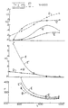
- Figs. 8 and 9 represent approximate results of actual laboratory tests on modified and unmodified Caterpillar 3300 Series turbocharged engines.
- Figs. 8 and 9 compare the rate of fuel consumption and amounts of noxious emissions produced by the embodiment illustrated in Figs. 1-7 of the present invention, burning 100 percent ethanol (E') or unleaded gasoline (G'), with a conventional fuel combustion system burning traditional Grade 2-D diesel fuel (D), and also with a fuel combustion system illustrated in Figs. 1-3 of U.S. Patent No. 4,548,172 burning 100 percent ethanol (E).
- All of the engines had a cylinder bore diameter of about 121 millimeters (4.75 inches) and a piston stroke of about 152 millimeters (6.00 inches); however, the engine tests burning diesel fuel (D) utilized an in-line six cylinder engine whereas all the other engine tests burning ethanol (E, E') or unleaded gasoline (G') utilized a single-cylinder engine.
- the conventional fuel combustion chamber burning diesel fuel basically differed from the illustrated embodiment of the present invention in that it had neither a fuel ignition-initiating means 26 nor a baffle means 30.
- the amounts of brake specific nitrogen oxide (NO), brake specific hydrocarbons (HC), and brake specific fuel consumption (F) are plotted as a function of varying engine load (L) at an approximately constant engine speed (N).
- the amounts of nitrogen oxide (NO) and hydrocarbons (HC) produced by the engines are measured in units of parts per million divided by one thousand (1000).
- the amount of brake specific fuel consumption (F) is measured in units of grams per kilowatt-hour; however, the fuel consumption results (F) for ethanol (E, E') and unleaded gasoline (G') are downwardly adjusted as if the energy content per gram of these fuels were the same as the actually higher energy content per gram of diesel fuel (D).
- the amount of varying engine load (L) is measured in terms of brake means effective pressure and is expressed in units of kilopascals.
- L The amount of varying engine load (L) is measured in terms of brake means effective pressure and is expressed in units of kilopascals.
- N constant engine speed
- rpm revolutions per minute
- N constant engine speed
- the amount of smoke-associated particulates produced by alcohols such as ethanol are naturally expected to be practically nonexistent as compared to the amount of smoke-associated particlates produced by diesel fuels (D).
- D diesel fuels
- the baseline diesel engine produced the lowest amounts of hydrocarbon (HC) emissions.
Abstract
Description
- This invention relates to a fuel combustion system in a direct-injection internal combustion engine and, more particularly, to such a fuel combustion system adapted to efficiently ignite and burn non-autoignitable fuels such as ethanol or methanol as well as autoignitable fuels such as traditional diesel fuel.
- In view of dwindling supplies of traditional diesel fuels, it would be very advantageous if conventional compression-ignition engines, more particularly direct-fuel-injection types, could be easily and inexpensively adapted to burn not only such diesel fuels but also alternative fuels such as 100 percent methanol or ethanol. Such alternative fuels are regarded as attractive substitutes for traditional diesel fuels because methanol can be feasibly synthesized from a wide variety of substances such as coal, natural gas, wood or animal waste. Moreover, ethanol can be feasibly produced by fermentation of starch derived from widely grown plants such as sugar cane or corn. Furthermore, the amounts of nitrogen oxides and smoke-associated particulates are inherently lower and practically nonexistent, respectively, when burning such alcohol fuels as compared to burning traditional diesel fuels.
- However, these alternative fuels are characterized by a cetane number of ignition value on the order of about 0-10 whereas traditional diesel fuels, such as Grade 2-D diesel fuel, are characterized by a cetane number of at least 40. Consequently, unlike traditional diesel fuels, these relatively lower-cetane-number alternative fuels do not readily autoignite under normal compression ratios and temperatures of about 538°C (1000°F), in an open combustion chamber of a compression-ignition engine, merely by contacting and mixing with intake air which has been compressed and thereby heated by a piston.
- Such relatively lower-cetane-number alternative fuels can be locally ignited with the aid of an electrically-energized glow plug or spark plug which directly heats a nearby air/fuel mixture to a sufficiently elevated temperature of about 1000°C (1832°F). However, another major problem exists of completely igniting and burning all of the alternative fuel that is directly injected into the open combustion chamber. This problem is due to the way fuel has been typically directly injected into the open combustion chamber of a modern compression-ignition engine.
- As shown in US-A-4,275,844, a conventional open combustion chamber of a direct-injection compression-ignition engine typically includes a relatively high-pressure fuel injector having a plurality of very small fuel spray orifices. These orifices periodically and simultaneously spray a plurality of distinct and evenly spaced high pressure fuel streams towards various peripheral portions of the open combustion chamber which is already filled with fresh intake air. This pattern of relatively concentrated conical fuel streams separated by sectors of fuel-deficient intake air, similar to the radial spokes of a wheel, is desirable for modern direct-injection engines to provide each fuel stream without enough kinetic energy so that it can quickly and adequately penetrate, atomize, mix, and combust with the required larger amounts of intake air before each cyclic power stroke of the open combustion chamber has substantially begun.
- If a glow plug or sprak plug is electrically-energized to produce a localized elevated temperature of about 1000°C (1832°F) and is positioned in close enough proximity to one of the mutually-spaced fuel streams of relatively lower-cetane-number alternative fuel, usually only that one fuel stream and other sufficiently close fuel streams will ignite. However, the fuel-deficient sectors of air separating each of the other remotely spaced fuel streams will prevent the flame from propagating to those other fuel streams. Consequently, the fuel streams which are not ignited, or are only partially burned, are exhausted from the open combustion chamber as either wasted raw fuel or incompletely combusted fuel. This, of course, significantly and undesirably reduces the fuel economy and power output of the engine and raises the level of noxious emissions, particularly hydrocarbons, exhausted from the open combustion chamber. Only at high engine loads is the combustion system less dependent on flame propagation for complete ignition because, under such conditions, the initial pressure rise and associated temperature rise may be sufficiently high to force autoignition of the remote fuel streams.
- In US-A-3,244,159, there is disclosed a fuel combustion system fashioned in such a way that an intensive swirling or unidirectional gas flow results in the combustion chamber during engine operation. A localized flame of burning fuel is started on a fuel stream injected adjacent to an igniting element and the flame and air/fuel mixture is moved along by that intensive swirling gas flow so that the flame contacts and ignites other injected fuel streams. However, the complete dependence upon swirling gas flow to achieve propagation of a flame through a non-autoignitable fuel carries the penalty of lower fuel economy due to increase heat rejection (i.e., the swirling gas flow disrupts the insulating gas boundary layer on the combustion chamber walls). Moreover, modifications, for example, to the air intake port(s) or to the air intake valve(s) for inducing intensive swirling gas flow also undesirably create gas flow restrictions which increase pumping losses of the engine and thereby further lower fuel economy.
- In US-A-4,548,172, there is shown a fuel combustion system including a multiple-orifice fuel injector, a fuel ignition-initiating means, a secondary fuel spray orifice, and an impingement surface element having a deflecting face spaced from the facing that secondary orifice. During engine operation, this arrangement effectively generates an auxiliary cloud of atomized fuel which interconnectedly bridges other mutually-spaced fuel streams so a flame can be rapidly propagated without depending on the existence of swirling gas flow. However, at above about one quarter to one half engine loads, such an arrangement may produce excessive smoke when burning non-oxygenated fuels such as diesel fuel or unleaded gasoline, respectivey. That is because the size of the secondary orifice is usually chosen in accordance with ensuring satisfactory engine operation at light engine loads and therefor the size of the secondary orifice may be somewhat too large for spraying non-oxygenated fuels when the engine is operated at heavy loads. Consequently, at heavy engine loads, too much non-oxygenated fuel may be sprayed through the secondary orifice such that the fuel is unable adequately to mix and combust with air. Furthermore, the above arrangement may require special modifications to standard off-the-shelf fuel injectors and/or pistons which add to the cost of the engine.
- DE-A-1 804 383 discloses a direct-injection internal combustion engine having a fuel combustion system which includes a combustion chamber; a plurality of fuel spray orifices each having a centreline axis directed outwardly into the combustion chamber; a fuel ignition-initiating means projecting directly into the combustion chamber and spaced a distance from at least one of the fuel spray orifices and also spaced from the centreline axis of this one fuel spray orifice; baffle means to intercept a portion of the fuel stream sprayed from the one spray orifice during engine operation, so that the intercepted fuel flows onto a surface of the baffle means, the surface facing the place where an initially localized flame of burning fuel is started by the fuel ignition-initiating means; and, according to the invention, such an engine is characterised in that the surface provides a line of sight to all the other fuel streams thereby controllably directing the resulting expanding flame of burning fuel to all of the other fuel streams sprayed from the other fuel spray orifices.
- With this construction the baffle means helps start a localized flame of burning fuel and then controlledly directs the resultant expanding flame of burning fuel to all of the other fuel streams sprayed from the fuel injector so that they are interconnectedly bridged with the flame and thereby positively ignited, to ensure complete and rapid combustion during each relatively brief combustion stroke. The baffle means also helps prevent fuel or gases from undesirably cooling the fuel ignition-initiating means during engine operation.
- The results of actual tests in direct-injection compression-ignition engines show that this improved fuel combustion system burning such alternative fuels exhibits about the same or even lower adjusted rate of fuel consumption as the conventional open combustion system burning traditional diesel fuel. Moreover, when this improved fuel combustion system burned 100 percent alternative fuels under most engine operating conditions, it produced about the same or even a lower level of nitrogen oxide emissions than that produced by a conventional open combustion system burning traditional diesel fuel.
- In the accompanying drawings:
- Fig. 1 is a diagrammatic partial cross-sectional side elevational view of one embodiment of the improved fuel combustion system as incorporated in a direct-injection internal combustion engine viewed from the rear end portion;
- Fig. 2 is a diagrammatic enlarged partial view of Fig. 1 taken within the area encircled by line II of Fig. 1;
- Fig. 3 is a diagrammatic partial view taken along line 111-111 of Fig. 1;
- Fig. 4 is a diagrammatic enlarged view of an adapter shown in Figs. 1 and 2;
- Fig. 5 is a diagrammatic plan view taken along line V-V of Fig. 4;
- Fig. 6 is a diagrammatic cross-sectional view taken along line VI-VI of Fig. 5;
- Fig. 7 is a diagrammatic enlarged partial view taken along line VII-VII of Fig. 4;
- Fig. 8 is a graph which approximately shows the comparative results of actual laboratory engine tests which measure the amounts of noxious emissions and adjusted fuel consumption as a function of varying engine load. These tests were run at a constant engine speed of about 1400 revolutions per minute (rpm); and
- Fig. 9 is a graph similar to Fig. 8 but approximately showing the results of similar tests run at a higher constant engine speed of about 2200 rpm.
- Referring to Figs. 1-7 wherein similar references characters designate similar elements or features throughout those figures, there is shown one embodiment of the improved fuel combustion system of the present invention.
- In Figs. 1-3, an improved
fuel combustion system 10 is shown as incorporated in a direct-injection internal combustion engine 14 (Fig. 1). For example, theengine 14 may have originally been a conventional compression-ignition engine which has been inexpensively and easily modified as described below. Thefuel combustion system 10 includes anopen combustion chamber 18; only asingle fuel injector 22; a fuel ignition-initiating means ordevice 26 for initiating localized ignition and flaming of fuel injected into theopen combustion chamber 18; and a unique baffle means 30 for intercepting a preselectedportion 34, 38 (Fig. 3) of such injected fuel, for temporarily maintaining that interceptedportion flame 42 of burning fuel, and for controlledly reflecting and directing the resultant expandingflame 42 of burning fuel to all of the other portion(s) of the injected fuel so that it is interconnectedly bridged with the flame and thereby positively ignited. - As defined herein, the
open combustion chamber 18 incorporates no flow restrictions that are sufficiently small to cause large differences in gas pressure between the different parts of the open combustion chamber during the combustion process. Theopen combustion chamber 18 is defined mainly by, for example, a conventional Mexican-hat-shaped crater wall 46 (Fig. 1) of an axially-reciprocable piston 50, shown at about the top dead center position of its periodic compression stroke, astationary cylinder liner 54 having acylindrical bore 58 in which thepiston 50 reciprocates, and abottom deck 62 of acylinder head 66 which clamps thecylinder liner 54 to anengine block 70. Preferably, theopen combustion chamber 18 is of the quiescent type so that the motion of gases therein is substantially random instead of being unidirectional or otherwise ordered. The quiescent type of open combustion chamber is preferably chosen because it provides a minimal level of turbulence and heat transfer which helps achieve low specific fuel consumption. Thereference numbers 74 in Fig. 3 indicate fresh intake air which is periodically admitted into the open combustion chamber by one of more intake poppet valves 78 and, following combustion, is discharged by one or more exhaust poppet valves 80. - The
fuel injector 22 may be, for example, a conventional fuel injection nozzle or a unit fuel pump injector and includes an elongated injector body 82 (Figs. 1-2) extending through a bore in thecylinder head 66. For properly orienting the directions of its fuel injection sprays, thefuel injector 22 may be accurately secured to thecylinder head 66, for example, by a clamping arrangement as described in US-A-4,206,725. Connected to one end portion of theinjector body 82 is a partly semi-spherical nozzle tip 86 (Figs. 1-3) which preferably projects directly into a central portion of theopen combustion chamber 18. Thenozzle tip 86 includes a plurality of evenly spacedfuel spray orifices 90, 94, 98 (Fig. 3), positioned circumferentially in a common horizontal plane, which are adapted during engine operation to simultaneously spray distinct and evenly spacedconical fuel streams open combustion chamber 18. For a quiescent open combustion chamber, the plurality of fuel spray orifices preferably total at least five and, for example, total nine evenly-space fuel spray orifices in Fig. 3. As apparent from Fig. 3, each of the fuel streams 102,106, 110 has an imaginary centerline axis, coincident with the centerline axis of each respective fuel spray orifice, and all of the fuel streams are mutually separated by fuel-deficient sectors 74 of the intake air. - In Figs. 1-3, the fuel ignition-initiating means 26 is shown, for example, as mainly including an elongated and electrically-
energizable glow plug 114 which is directly and threadedly connected inside a generally cylindrical andhollow adapter 118 that is threadedly connected to or otherwise supported in another bore of thecylinder head 66. As shown in Fig. 1, theadapter 118 extends completely through thecylinder head 66 and is seated against an annular seal 122 disposed in acounterbore 126 of thebottom deck 62. Theadapter 118 and the seal 122 which, for example, may be made of stainless steel and copper- bronze alloy, respectively, function to protect theglow plug 114 from directly contacting liquid coolant which is circulated during engine operation throughinternal chambers 130 of thecylinder head 66. Alternatively, in lieu of providing theadaptor 118, thecylinder head 66 may be provided with a cast-in or otherwise integral boss havig a bore directly through which theglow plug 114 extends to seat against the seal 122. - At a free end of the
glow plug 114 is an electrical resistance element 134 (Figs. 2-3) of, for example, circular or generally rectangular cross-section which also projects directly into the central portion of theopen combustion chamber 18 so that it is unobstructively spaced a preselected distance L, (Fig. 3) from at least one, and preferably a pair of, selectedfuel spray orifices 90,94 of thenozzle tip 86. Moreover, the fuel ignition-initiating means 26 is positioned in spaced relation between the centerline axes of the pathways of the respective pair ofadjacent fuel streams electrical resistance element 134 and to avoid cracking of fuel caused by direct surface impingement thereon of the relatively dense portions of thosefuel streams - Alternatively, the fuel ignition-initiating
means 26 may mainly include, instead of theglow plug 114, an electrically-energizable spark plug or some other high energy device which, during engine operation, can be continuously or intermittently energized to locally heat the nearby fuel to a predetermined and elevated fuel igniting temperature that is sufficient to start ignition of the relatively lower-cetane-number alternative fuel. If a spark plug is substituted for theglow plug 114, thereference number 134 would refer to an electrode element of the spark plug. - The baffle means 30 is preferably a rigid baffle 138 (Figs. 3, 4, 6, 7) which, for example, is formed as an integral extension of one end portion of the
adapter 118. Alternatively, thebaffle 138 may be formed as an integral extension of the body of theglow plug 114 when an integral boss of thecylinder head 66 is used to directly mount theglow plug 114 in lieu of theadapter 118. As another alternative, thebaffle 138 may be formed as an integral extension of the seal 122 whether or not theadapter 118 is used. As another alternative, thebaffle 138 may be connected to thebottom deck 62 of thecylinder head 66. Thebaffle 138 projects directly into theopen combustion chamber 18 and preferably includes a tubular andbeveled end portion 142 positioned in generally concentrically spaced relation partially around theelectrical resistance element 134. The interior of thebeveled end portion 142 defines an imperforate and generally semicylindricalconcave surface 146. Theconcave surface 146 generally faces and is spaced from the selected pair of adjacentfuel spray orifices 90, 94 according to a second preselected distance L2 which is greater than the first preselected distance L, so that the fuel ignition-initiatingmeans 26 is positioned in spaced relation directly between the selected pair of adjacentfuel spray orifices 90, 94 of thefuel injector 22 and theconcave surface 146 of thebaffle 138. - As shown in Fig. 5, the free end of the
beveled end portion 142 forms an angle, A,, relative to a longitudinal axis of thebaffle 138 in order to define a single and generallyelongate opening 150. The size and orientation of theopening 150 is chosen so that it is sufficiently large enough to expose theconcave surface 146 generally towards both the selected pair offuel spray orifices 90, 94 and all of the pathways of theother fuel streams 110 sprayed from thefuel injector 22 during engine operation. Generally, for a given fuel stream pattern and inside diameter of the beveled end portion as illustrated, the magnitude of the angle, A" will decrease as the orientation of the longitudinal axis of theelectrical resistance element 134 is chosen to be more vertical relative to the horizontal plane of thefuel spray orifices electrical resistance element 134 is chosen to be more horizontal relative to the horizontal plane of the fuel spray orifices. The maximum size of theconcave surface 146 is chosen so that the concave surface intercepts less than one half, and preferably about one third, of the total stoichiometric volume of air/fuel mixture of each of the selected pair ofadjacent fuel streams fuel spray orifices 90, 94 during engine operation. The minimum outer surface area of thebeveled end portion 142 is preferably chosen so that the beveled end portion can partially shield the fuel ignition-initiatingmeans 26 from being cooled during engine operation bygases 74 moving randomly in theopen combustion chamber 18. - The end portion of the
adapter 118 opposite to thebeveled end portion 142 is preferably provided with a reference mark (not shown) to visually verify, during assembly, proper alignment between theconcave surface 146 of thebaffle 138 and the selectedfuel spray orifices 90, 94 of thefuel injector 22. If thebaffle 138 is, alternatively, formed as an integral extension of the seal 122, a complementary tongue and groove arrangement may be formed between the seal 122 and thecounterbore 126 of thebottom deck 62 for ensuring proper alignment of theconcave surface 146. - By provision of the improved
fuel combustion system 10 of the present invention, alocalized flame 42 of burning fuel initiated by the fuel ignition-initiatingmeans 26 is rapidly and completely propagated to all of the fuel which is directly injected into theopen combustion chamber 18. - Periodically, as the
reciprocating piston 50 approaches the top dead center position of its compression stroke, relatively high pressure fuel is simultaneously injected generally radially outwardly into theopen combustion chamber 18 through all of thefuel spray orifices fuel injector 22. The injected fuel sprayed from thefuel spray orifices quiescent intake air 74. The extent of penetration by the fuel streams directly varies with the amount of engine load so that, at about full engine load, the fuel streams 102, 106, 110 generally reach the outer peripheral portions of theopen combustion chamber 18 as illustrated in Fig. 3. - A preselected
outer portion respective fuel stream fuel spray orifices 90, 94 is intercepted by theconcave surface 146 of thebaffle 138. An outer portion of each respective fuel stream 102,106 is chosen to be intercepted by theconcave surface 146 because each outer portion exhibits stoichiometric proportions of well-mixed fuel andair 74. Theconcave surface 146 controlledly deflects the interceptedportions means 26 and theconcave surface 146. Theconcave surface 146 of thebaffle 138, in cooperation with the respective pair ofadjacent fuel streams means 26, temporarily confines and maintains those interceptedportions means 26. - The fuel ignition-initiating
means 26 is either intermittently or continuously energized during engine operation. If the fuel ignition-initiatingmeans 26 includes aglow plug 114, the glow plug is electrically energized and itselectrical resistance element 134 is thereby heated to a preselected elevated temperature. Theelectrical resistance element 134 positively ignites the intercepted and temporarily confinedportions dense fuel streams resultant flame 42 of burning fuel will expand, for example, by about 50 to 500 times that volume depending upon engine load. Consequently, the expandingflame 42 is controlledly reflected by theconcave surface 146 and/or directed through theoblong opening 150 of thebaffle 138 to all of theother fuel streams 110 so that they are interconnectedly bridged with theflame 42 and thereby positively and rapidly ignited. - The baffle means 30 is easily and inexpensively manufactured as an integral extension of the
adapter 118, or the fuel ignition-initiatingmeans 26, or the seal 122. Another advantage of providing the baffle means 30 is that it helps prolong the life of the fuel ignition-initiatingmeans 26 when aglow plug 114 is used. That is because the glow plug requires, for example, about one ampere less of electrical current to maintain a sufficiently elevated fuel igniting temperature when the glow plug is partially shielded by the baffle means 30 from gas cooling. Moreover, direct fuel impingement upon the fuel ignition-initiating means for ignition is avoided which prevents undesirable cracking of fuel and resultant excessive smoke and noxious emissions, particularly with non-oxygenated hydrocarbon fuels. - Figs. 8 and 9 represent approximate results of actual laboratory tests on modified and unmodified Caterpillar 3300 Series turbocharged engines. Figs. 8 and 9 compare the rate of fuel consumption and amounts of noxious emissions produced by the embodiment illustrated in Figs. 1-7 of the present invention, burning 100 percent ethanol (E') or unleaded gasoline (G'), with a conventional fuel combustion system burning traditional Grade 2-D diesel fuel (D), and also with a fuel combustion system illustrated in Figs. 1-3 of U.S. Patent No. 4,548,172 burning 100 percent ethanol (E). All of the engines had a cylinder bore diameter of about 121 millimeters (4.75 inches) and a piston stroke of about 152 millimeters (6.00 inches); however, the engine tests burning diesel fuel (D) utilized an in-line six cylinder engine whereas all the other engine tests burning ethanol (E, E') or unleaded gasoline (G') utilized a single-cylinder engine. The conventional fuel combustion chamber burning diesel fuel basically differed from the illustrated embodiment of the present invention in that it had neither a fuel ignition-initiating
means 26 nor a baffle means 30. - Various exemplary parameters of the illustrated and actually tested embodiment of the present invention for burning 100 percent ethanol or unleaded gasoline were approximately as follows (in some cases the parameters varied over an approximate range according to engine load):

- In both Figs. 8 and 9, the amounts of brake specific nitrogen oxide (NO), brake specific hydrocarbons (HC), and brake specific fuel consumption (F) are plotted as a function of varying engine load (L) at an approximately constant engine speed (N). The amounts of nitrogen oxide (NO) and hydrocarbons (HC) produced by the engines are measured in units of parts per million divided by one thousand (1000). The amount of brake specific fuel consumption (F) is measured in units of grams per kilowatt-hour; however, the fuel consumption results (F) for ethanol (E, E') and unleaded gasoline (G') are downwardly adjusted as if the energy content per gram of these fuels were the same as the actually higher energy content per gram of diesel fuel (D). The amount of varying engine load (L) is measured in terms of brake means effective pressure and is expressed in units of kilopascals. In Fig. 8, the tests were run at a constant engine speed (N) of about 1400 revolutions per minute (rpm) which represents the peak torque speed of the engines whereas the tests of Fig. 9 were run at a constant engine speed (N) of about 2200 rpm which represents the rated speed of the engines.
- From Figs. 8 and 9, it is observed that the
fuel combustion system 10 of the present invention burning 100 percent ethanol (E') or unleaded gasoline (G') efficiently combusts such fuel at about the same or even a lower adjusted rate of fuel consumption per kilowatt-hour produced as the conventional fuel combustion chamber engine burning diesel fuel (D). Of course, generally in any fuel combustion system, the amount of nitrogen oxide (NO) produced by alcohols such as ethanol are naturally expected to be advantageously lower than that produced by diesel fuels (D). Similarly, while not illustrated in either Figs. 8 or 9, generally in any fuel combustion system, the amount of smoke-associated particulates produced by alcohols such as ethanol are naturally expected to be practically nonexistent as compared to the amount of smoke-associated particlates produced by diesel fuels (D). At low engine loads, the baseline diesel engine produced the lowest amounts of hydrocarbon (HC) emissions. - The low level of nitrogen oxide emissions and generally excellent level of fuel consumption for a given power output, particularly at higher engine loads, highlights the effectiveness of the present invention. Without the addition of the fuel ignition-initiating
means 26 and the baffle means 30, a significant amount of such alternative fuel injected into a conventional open combustion chamber would not be ignited or would not burn completely, resulting in either much less engine power output, higher fuel consumption, and higher noxious hydrocarbon (HC) emissions or even total inoperability of the engine.
Claims (10)
Applications Claiming Priority (2)
| Application Number | Priority Date | Filing Date | Title |
|---|---|---|---|
| US870266 | 1986-06-03 | ||
| US06/870,266 US4721081A (en) | 1986-06-03 | 1986-06-03 | Flame incubating and propagating apparatus for a fuel combustion system |
Publications (2)
| Publication Number | Publication Date |
|---|---|
| EP0309458A1 EP0309458A1 (en) | 1989-04-05 |
| EP0309458B1 true EP0309458B1 (en) | 1991-01-09 |
Family
ID=25355047
Family Applications (1)
| Application Number | Title | Priority Date | Filing Date |
|---|---|---|---|
| EP87903175A Expired - Lifetime EP0309458B1 (en) | 1986-06-03 | 1987-04-30 | Flame incubating and propagating apparatus for a fuel combustion system |
Country Status (8)
| Country | Link |
|---|---|
| US (1) | US4721081A (en) |
| EP (1) | EP0309458B1 (en) |
| JP (1) | JP2590170B2 (en) |
| BR (1) | BR8707722A (en) |
| CA (1) | CA1283585C (en) |
| DE (1) | DE3767307D1 (en) |
| WO (1) | WO1987007678A1 (en) |
| ZA (1) | ZA873547B (en) |
Families Citing this family (44)
| Publication number | Priority date | Publication date | Assignee | Title |
|---|---|---|---|---|
| US4925385A (en) * | 1989-07-31 | 1990-05-15 | Mccord Jr Harry C | Fuel igniter |
| US5075536A (en) * | 1990-05-17 | 1991-12-24 | Caterpillar Inc. | Heating element assembly for glow plug |
| US5084606A (en) * | 1990-05-17 | 1992-01-28 | Caterpillar Inc. | Encapsulated heating filament for glow plug |
| US5499615A (en) * | 1994-10-28 | 1996-03-19 | Caterpillar Inc. | Direct injection propane fuel system for diesel engine applications |
| US5601061A (en) * | 1996-05-16 | 1997-02-11 | Caterpillar Inc. | Engine intake air deflector |
| US5676100A (en) * | 1996-08-30 | 1997-10-14 | Caterpillar Inc. | Glow plug assembly |
| US5693874A (en) * | 1996-10-11 | 1997-12-02 | Southwest Research Institute | Test apparatus and method for determining deposit formation characteristics of fuels |
| US5771857A (en) * | 1996-11-06 | 1998-06-30 | Caterpillar Inc. | Direct injected gas engine with variable gas pressure control apparatus and method of operation |
| JPH10288131A (en) * | 1997-04-11 | 1998-10-27 | Yanmar Diesel Engine Co Ltd | Injection nozzle of diesel engine |
| US6138637A (en) * | 1997-09-18 | 2000-10-31 | Daimlerchrysler Ag | Internal combustion engine with direct fuel injection |
| DE19743060A1 (en) * | 1997-09-30 | 1999-04-01 | Bosch Gmbh Robert | Method for operating an internal combustion engine and fuel injection system for carrying out the method |
| JPH11182249A (en) * | 1997-12-18 | 1999-07-06 | Nissan Motor Co Ltd | Direct injection spark-ignition type internal combustion engine |
| FR2807103B1 (en) * | 2000-04-04 | 2003-02-07 | Peugeot Citroen Automobiles Sa | COMBUSTION CHAMBER FOR DIRECT IGNITION AND DIRECT INJECTION ENGINE |
| DE10026321A1 (en) | 2000-05-26 | 2001-11-29 | Bosch Gmbh Robert | Fuel injection system and method for injection |
| DE10048608C2 (en) * | 2000-09-30 | 2003-04-03 | Bosch Gmbh Robert | Method and computer program for operating an internal combustion engine and internal combustion engine |
| US6460512B1 (en) * | 2000-10-16 | 2002-10-08 | International Engine Intellectual Property Company, L.L.C. | Combustion gasket having dual material structures |
| WO2002033236A2 (en) * | 2000-10-22 | 2002-04-25 | Westport Germany Gmbh | Internal combustion engine with injection of gaseous fuel |
| US7040281B2 (en) * | 2000-10-22 | 2006-05-09 | Westport Research Inc. | Method of injecting a gaseous fuel into an internal combustion engine |
| US7281515B2 (en) * | 2000-10-22 | 2007-10-16 | Westport Power Inc. | Method of injecting a gaseous fuel into an internal combustion engine |
| FR2830570B1 (en) * | 2001-10-10 | 2004-02-13 | Peugeot Citroen Automobiles Sa | INTERNAL COMBUSTION ENGINE, DIRECT IGNITION, AND DIRECT FUEL INJECTION, COMPRISING A DIRECT INJECTION SYSTEM WITH VERY HIGH PRESSURE |
| CA2412571A1 (en) * | 2002-11-15 | 2004-05-15 | Westport Research Inc. | Direct injection gaseous fuel engine with ignition assist |
| DE602004002108T2 (en) | 2003-04-16 | 2006-12-21 | Westport Research Inc., Vancouver | INTERNAL COMBUSTION ENGINE WITH GAS INJECTION |
| US6918243B2 (en) * | 2003-05-19 | 2005-07-19 | The Boeing Company | Bi-propellant injector with flame-holding zone igniter |
| DE10331267A1 (en) * | 2003-07-10 | 2005-02-03 | Robert Bosch Gmbh | fuel injection system |
| JP4135926B2 (en) * | 2003-10-14 | 2008-08-20 | 株式会社日立製作所 | Fuel injection valve for internal combustion engine and internal combustion engine |
| JP4103858B2 (en) * | 2004-07-07 | 2008-06-18 | いすゞ自動車株式会社 | Fuel injection / ignition assistance device and fuel injection / ignition assistance method for in-cylinder injection internal combustion engine |
| US7314033B2 (en) | 2004-11-18 | 2008-01-01 | Massachusetts Institute Of Technology | Fuel management system for variable ethanol octane enhancement of gasoline engines |
| US8082735B2 (en) | 2005-04-06 | 2011-12-27 | Massachusetts Institute Of Technology | Optimized fuel management system for direct injection ethanol enhancement of gasoline engines |
| US8353269B2 (en) * | 2004-11-18 | 2013-01-15 | Massachusetts Institute Of Technology | Spark ignition engine that uses intake port injection of alcohol to extend knock limits |
| US20080060627A1 (en) * | 2004-11-18 | 2008-03-13 | Massachusetts Institute Of Technology | Optimized fuel management system for direct injection ethanol enhancement of gasoline engines |
| US7640913B2 (en) * | 2006-03-08 | 2010-01-05 | Ethanol Boosting Systems, Llc | Single nozzle injection of gasoline and anti-knock fuel |
| WO2007106416A2 (en) * | 2006-03-10 | 2007-09-20 | Ethanol Boosting Systems, Llc. | Fuel tank system for direct ethanol injection octane boosted gasoline engine |
| US8122703B2 (en) | 2006-04-28 | 2012-02-28 | United Technologies Corporation | Coaxial ignition assembly |
| WO2008014265A2 (en) * | 2006-07-24 | 2008-01-31 | Ethanol Boosting Systems, Llc | Single nozzle direct injection system for rapidly variable gasoline/anti-knock agent mixtures |
| KR101319491B1 (en) * | 2006-09-21 | 2013-10-17 | 삼성전자주식회사 | Apparatus and method for setting up domain information |
| US7753025B2 (en) * | 2008-04-11 | 2010-07-13 | Southwest Research Institute | Surface ignition mechanism for diesel engines |
| WO2010003001A1 (en) * | 2008-07-03 | 2010-01-07 | Dow Global Technologies Inc. | Improved method of operating a compression ignition internal combustion engine |
| US8522758B2 (en) | 2008-09-12 | 2013-09-03 | Ethanol Boosting Systems, Llc | Minimizing alcohol use in high efficiency alcohol boosted gasoline engines |
| US20110209683A1 (en) * | 2008-11-20 | 2011-09-01 | Simmons Brandon M | Method of operating a spark ignition internal combustion engine |
| US8813713B2 (en) | 2010-12-22 | 2014-08-26 | Caterpillar Inc. | Piston with cylindrical wall |
| US20130073183A1 (en) | 2011-09-16 | 2013-03-21 | Ethanol Boosting Systems Llc | Open-valve Port Fuel Injection Of Alcohol In Multiple Injector Engines |
| US8291884B2 (en) * | 2011-09-29 | 2012-10-23 | Ford Global Technologies, Llc | Multi-zone gaseous fuel high efficiency engine |
| KR102072703B1 (en) * | 2013-04-29 | 2020-02-03 | 대동공업주식회사 | Direct injection type combustion engine |
| CN103993956A (en) * | 2014-05-26 | 2014-08-20 | 运城常运动力机械有限公司 | Methyl alcohol internal combustion engine |
Citations (2)
| Publication number | Priority date | Publication date | Assignee | Title |
|---|---|---|---|---|
| US324415A (en) * | 1885-08-18 | lewis c | ||
| US4548172A (en) * | 1983-06-22 | 1985-10-22 | Caterpillar Tractor Co. | Ignition-assisted fuel combustion system |
Family Cites Families (19)
| Publication number | Priority date | Publication date | Assignee | Title |
|---|---|---|---|---|
| US920989A (en) * | 1904-10-15 | 1909-05-11 | William M Power | Combustion-engine. |
| US971954A (en) * | 1909-07-28 | 1910-10-04 | Leon Wygodsky | Liquid-fuel internal-combustion engine. |
| US1341478A (en) * | 1919-02-12 | 1920-05-25 | Joseph Reid Gas Engine Company | Internal-combustion engine |
| US1362210A (en) * | 1919-05-15 | 1920-12-14 | Wheeler Thomas | Fuel-injector for engines |
| US2058487A (en) * | 1931-01-26 | 1936-10-27 | Bendix Res Corp | Internal combustion engine |
| DE1804383U (en) | 1957-11-09 | 1960-01-21 | Westinghouse Electric Corp | LIQUID COOLING FOR ELECTRIC MACHINERY. |
| GB966534A (en) * | 1962-03-03 | 1964-08-12 | Maschf Augsburg Nuernberg Ag | Improvements in and relating to internal combustion engines |
| GB1062174A (en) * | 1962-09-13 | 1967-03-15 | Augsberg Nuernberg A G Maschf | Improvements in and relating to internal combustion engines |
| FR1334129A (en) * | 1962-09-20 | 1963-08-02 | Maschf Augsburg Nuernberg Ag | Ignition device for internal combustion engines with injection |
| DE1804383A1 (en) * | 1968-10-22 | 1970-07-02 | Daimler Benz Ag | Air-compressing, externally ignited internal combustion engine |
| US4091774A (en) * | 1973-12-05 | 1978-05-30 | Minoru Kamiya | Stratified combustion type engine |
| US4187825A (en) * | 1977-10-17 | 1980-02-12 | Curtiss-Wright Corporation | Pilot fuel ignited stratified charge rotary combustion engine and fuel injector therefor |
| WO1980001189A1 (en) * | 1978-11-29 | 1980-06-12 | Caterpillar Tractor Co | Injection nozzle clamp |
| US4286557A (en) * | 1979-09-21 | 1981-09-01 | General Motors Corporation | Target injection stratified charge spark ignition engine |
| US4275844A (en) * | 1979-11-30 | 1981-06-30 | Caterpillar Tractor Co. | Fuel injection nozzle |
| DE2951029A1 (en) * | 1979-12-19 | 1981-06-25 | Robert Bosch Gmbh, 7000 Stuttgart | EXTERNAL COMBUSTION ENGINE WITH ONE MAIN COMBUSTION CHAMBER PER CYLINDER AND ONE IGNITION CHAMBER |
| US4444166A (en) * | 1981-06-16 | 1984-04-24 | Kovacs Research Center, Inc. | Method and apparatus for reducing the operating compression ratios of compression ignition engines |
| JPS58120870A (en) * | 1982-01-06 | 1983-07-18 | 中平 智丈 | Apparatus for cutting continuously knitted sock fabric |
| JPS5979031A (en) * | 1982-10-29 | 1984-05-08 | Isuzu Motors Ltd | Direct-injection type diesel engine |
-
1986
- 1986-06-03 US US06/870,266 patent/US4721081A/en not_active Expired - Lifetime
-
1987
- 1987-04-30 EP EP87903175A patent/EP0309458B1/en not_active Expired - Lifetime
- 1987-04-30 DE DE8787903175T patent/DE3767307D1/en not_active Expired - Fee Related
- 1987-04-30 BR BR8707722A patent/BR8707722A/en unknown
- 1987-04-30 WO PCT/US1987/000963 patent/WO1987007678A1/en active IP Right Grant
- 1987-04-30 JP JP62502869A patent/JP2590170B2/en not_active Expired - Lifetime
- 1987-05-18 ZA ZA873547A patent/ZA873547B/en unknown
- 1987-06-02 CA CA000538624A patent/CA1283585C/en not_active Expired - Fee Related
Patent Citations (2)
| Publication number | Priority date | Publication date | Assignee | Title |
|---|---|---|---|---|
| US324415A (en) * | 1885-08-18 | lewis c | ||
| US4548172A (en) * | 1983-06-22 | 1985-10-22 | Caterpillar Tractor Co. | Ignition-assisted fuel combustion system |
Also Published As
| Publication number | Publication date |
|---|---|
| BR8707722A (en) | 1989-08-15 |
| WO1987007678A1 (en) | 1987-12-17 |
| DE3767307D1 (en) | 1991-02-14 |
| EP0309458A1 (en) | 1989-04-05 |
| CA1283585C (en) | 1991-04-30 |
| JP2590170B2 (en) | 1997-03-12 |
| JPH01502765A (en) | 1989-09-21 |
| US4721081A (en) | 1988-01-26 |
| ZA873547B (en) | 1988-03-30 |
Similar Documents
| Publication | Publication Date | Title |
|---|---|---|
| EP0309458B1 (en) | Flame incubating and propagating apparatus for a fuel combustion system | |
| AU561979B2 (en) | Ignition-assisted fuel combustion system | |
| US5522357A (en) | Apparatus and method of fuel injection and ignition of internal combustion engine | |
| US6845746B2 (en) | Internal combustion engine with injection of gaseous fuel | |
| US4966103A (en) | Combustion system for dual fuel engine | |
| CA2046602A1 (en) | Piston and process for achieving controlled ignition | |
| EP0025298B1 (en) | Catalytic combustion engines | |
| JPH0579331A (en) | Air compression and valve operating type internal combustion engine | |
| US4126106A (en) | Mixed cycle internal combustion engine | |
| JP2574239B2 (en) | Apparatus and method for generating agitated flow in an internal combustion engine | |
| KR100306600B1 (en) | Piston for direct injection type gasoline engine | |
| JP3695011B2 (en) | Sub-chamber engine | |
| JP2778846B2 (en) | Methanol engine | |
| JPH09268916A (en) | Diesel engine with fuel of heavy oil | |
| JPH09317470A (en) | Diesel engine for low volatile fuel | |
| JPH09317471A (en) | Diesel engine using low quality fuel | |
| JPH0755295Y2 (en) | Combustion chamber of internal combustion engine | |
| JP2521914B2 (en) | Internal combustion engine | |
| JPS6140414A (en) | Injection timing for injection device of internal-combustion engine | |
| JPH07259567A (en) | Direct-injection type compression ignition internal combustion engine | |
| KR20180068191A (en) | Cylinder head structure | |
| KR19990003807A (en) | Combustion chamber of direct injection diesel engine | |
| JPH08218876A (en) | Direct injection type diesel engine | |
| JP2012172677A (en) | Premixed flame ignition engine | |
| JPH051826U (en) | In-cylinder direct injection engine combustion chamber |
Legal Events
| Date | Code | Title | Description |
|---|---|---|---|
| PUAI | Public reference made under article 153(3) epc to a published international application that has entered the european phase |
Free format text: ORIGINAL CODE: 0009012 |
|
| 17P | Request for examination filed |
Effective date: 19881201 |
|
| AK | Designated contracting states |
Kind code of ref document: A1 Designated state(s): DE FR GB |
|
| 17Q | First examination report despatched |
Effective date: 19900307 |
|
| GRAA | (expected) grant |
Free format text: ORIGINAL CODE: 0009210 |
|
| AK | Designated contracting states |
Kind code of ref document: B1 Designated state(s): DE FR GB |
|
| REF | Corresponds to: |
Ref document number: 3767307 Country of ref document: DE Date of ref document: 19910214 |
|
| ET | Fr: translation filed | ||
| PLBE | No opposition filed within time limit |
Free format text: ORIGINAL CODE: 0009261 |
|
| STAA | Information on the status of an ep patent application or granted ep patent |
Free format text: STATUS: NO OPPOSITION FILED WITHIN TIME LIMIT |
|
| 26N | No opposition filed | ||
| PGFP | Annual fee paid to national office [announced via postgrant information from national office to epo] |
Ref country code: GB Payment date: 19990225 Year of fee payment: 13 Ref country code: DE Payment date: 19990225 Year of fee payment: 13 |
|
| PGFP | Annual fee paid to national office [announced via postgrant information from national office to epo] |
Ref country code: FR Payment date: 19990331 Year of fee payment: 13 |
|
| PG25 | Lapsed in a contracting state [announced via postgrant information from national office to epo] |
Ref country code: GB Free format text: LAPSE BECAUSE OF NON-PAYMENT OF DUE FEES Effective date: 20000430 |
|
| GBPC | Gb: european patent ceased through non-payment of renewal fee |
Effective date: 20000430 |
|
| PG25 | Lapsed in a contracting state [announced via postgrant information from national office to epo] |
Ref country code: FR Free format text: LAPSE BECAUSE OF NON-PAYMENT OF DUE FEES Effective date: 20001229 |
|
| PG25 | Lapsed in a contracting state [announced via postgrant information from national office to epo] |
Ref country code: DE Free format text: LAPSE BECAUSE OF NON-PAYMENT OF DUE FEES Effective date: 20010201 |
|
| REG | Reference to a national code |
Ref country code: FR Ref legal event code: ST |