EP0307251A2 - Ink jet recording apparatus and method of preventing dewing therefor - Google Patents
Ink jet recording apparatus and method of preventing dewing therefor Download PDFInfo
- Publication number
- EP0307251A2 EP0307251A2 EP88308408A EP88308408A EP0307251A2 EP 0307251 A2 EP0307251 A2 EP 0307251A2 EP 88308408 A EP88308408 A EP 88308408A EP 88308408 A EP88308408 A EP 88308408A EP 0307251 A2 EP0307251 A2 EP 0307251A2
- Authority
- EP
- European Patent Office
- Prior art keywords
- humidity
- ink jet
- recording apparatus
- jet recording
- temperature
- Prior art date
- Legal status (The legal status is an assumption and is not a legal conclusion. Google has not performed a legal analysis and makes no representation as to the accuracy of the status listed.)
- Granted
Links
Images


Classifications
-
- B—PERFORMING OPERATIONS; TRANSPORTING
- B41—PRINTING; LINING MACHINES; TYPEWRITERS; STAMPS
- B41J—TYPEWRITERS; SELECTIVE PRINTING MECHANISMS, i.e. MECHANISMS PRINTING OTHERWISE THAN FROM A FORME; CORRECTION OF TYPOGRAPHICAL ERRORS
- B41J2/00—Typewriters or selective printing mechanisms characterised by the printing or marking process for which they are designed
- B41J2/005—Typewriters or selective printing mechanisms characterised by the printing or marking process for which they are designed characterised by bringing liquid or particles selectively into contact with a printing material
- B41J2/01—Ink jet
- B41J2/17—Ink jet characterised by ink handling
- B41J2/20—Ink jet characterised by ink handling for preventing or detecting contamination of compounds
-
- B—PERFORMING OPERATIONS; TRANSPORTING
- B41—PRINTING; LINING MACHINES; TYPEWRITERS; STAMPS
- B41J—TYPEWRITERS; SELECTIVE PRINTING MECHANISMS, i.e. MECHANISMS PRINTING OTHERWISE THAN FROM A FORME; CORRECTION OF TYPOGRAPHICAL ERRORS
- B41J11/00—Devices or arrangements of selective printing mechanisms, e.g. ink-jet printers or thermal printers, for supporting or handling copy material in sheet or web form
- B41J11/0015—Devices or arrangements of selective printing mechanisms, e.g. ink-jet printers or thermal printers, for supporting or handling copy material in sheet or web form for treating before, during or after printing or for uniform coating or laminating the copy material before or after printing
- B41J11/002—Curing or drying the ink on the copy materials, e.g. by heating or irradiating
- B41J11/0024—Curing or drying the ink on the copy materials, e.g. by heating or irradiating using conduction means, e.g. by using a heated platen
Definitions
- the present invention relates to an ink jet recording apparatus, and more particularly to an ink jet recording apparatus provided with a fixing heater for accelerating fixation of the ink deposited as a recorded image on a recording medium.
- the ink jet recording apparatus are attaching increasing attention in the field of recording apparatus, because of various advantages such as very low noise level at the recording and capability of a high density recording.
- the ink jet recording apparatus have an advantage that it can use plain paper as the recording medium, but the fixation of the ink on a recording paper may be difficult depending on the combination of the recording sheet to be employed and the ink. Since the ink jet recording apparatus employs liquid ink as the recording material, the ink may not penetrate rapidly into the recording medium and remain in liquid state thereon if the recording medium shows insufficient absorption to the ink.
- the deterioration of the recorded image quality may also be caused by dewing in the ink jet recording apparatus. Under certain circumferential conditions the moisture condensed by dewing in the apparatus may adhere to the recording medium, causing ink blotting. Such problems resulting from dewing cannot be prevented by the use of a fixing heater.
- the present inventors have noticed, in a different technical area, the electrophotographic technology, and have considered application of a dew-preventing device employed in electrophotographic copying machines to the ink jet recording apparatus. For example, they tried a method of controlling a heating operation of plurality of heaters provided respectively for plurality of temperature sensors, single humidity sensor, paper feeding section, optical unit and fixing unit as described in Japanese Patent-Laid-Open No.55-35390, and a method of removing moisture by blower as described Japanese Patent Laid Open No.56-80061 in addition to the above described heat control method.
- the recording head is maintained at 20° to 40°C in consideration of parameter influencing the stability of ink emission such as ink viscosity.
- This temperature is lower than the circumferential temperature.
- emission surface the face of the ink emission orifices of the recording head
- dewing because a high humidity atmosphere is created around the recording, particularly in the vicinity of the emission surface, due to water evaporation from the recording medium and from the ink by heating for fixing.
- the ink droplet In the ink jet recording, it is generally important that the ink droplet is deposited at a desired position, in order to improve the image quality, and, for this purpose, it is required that the ink droplets for use in recording have constant flying direction and speed of emission with a uniform size.
- an object of the present invention is to provide a method of preventing dewing in the ink jet recording apparatus, which minimizes the dewing on the emission surface and thus stabilizes the direction and speed of emission of ink droplets and the size thereof, thereby preventing deterioration of the recorded image quality, and an ink jet recording apparatus achieving such method.
- Another object of the present invention is to provide an ink jet recording apparatus provided with a recording head for emitting ink for image recording on a recording medium; heater means for heating the recording medium; humidity detector means for detecting the humidity in a recording zone formed by the recording head and the recording medium; and control means for controlling the temperature of the heater means according to the humidity detected by the humidity detector means.
- Still another object of the present invention is to provide an ink jet recording apparatus provided with first heater means for preheating recorded area of the recording medium prior to image recording; second heater means for heating the recording medium after recording thereby fixing the recorded image; humidity detector means for detecting the humidity in the vicinity of the zone of the recording medium is subjected to image recording; and control means for controlling the temperatures of the first and second heater means according to the humidity detected by the humidity detector means.
- Still another object of the present invention is to provide an ink jet recording apparatus with heater means for heating the recording medium for fixing the recorded image, provided with first humidity detector means for detecting the humidity of a zone in which the recording medium is subjected to image recording; second humidity detector means for detecting the ambient humidity outside the ink jet recording apparatus; and control means for controlling the temperature of the heater means according to the humidities detected by the first and second humidity detector means.
- the ink jet recording apparatus is equipped with at least one humidity detector means and at least one fixing heater means, wherein heating temperature of said heater means is varied according to the humidity detected by said humidity detector means. It is also preferred to suitably vary the temperature of the recording head itself. More specifically, (1) if a high humidity is detected by the humidity detector means, the heating by the heater means is interrupted or adjusted to a temperature lower than the normal fixing temperature, thereby preventing rapid humidity rise and thus avoiding dewing; or (2) in such situation temperature of the recording head itself is brought to a temperature higher than the normal heating temperature, thereby reducing dewing tendency thereon. Besides, the combination of the above-mentioned methods (1) and (2) reduces the temperature difference between temperature of the recording head and temperature of the atmosphere therearound, thus preventing the dewing on the recording head or reducing it so that substantially no adverse effect would be caused.
- the preferred temperature range for the heating means is not exceeding 80°C, more preferably from 60° to 80°C, and that temperature region the recording head itself is suitably selected according to a kind and property of ink to be used, 20° to 40°C is desirable for the region.
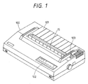
- Fig. 1 is a schematic external perspective view of an ink jet recording apparatus (hereinafter briefly called ink jet printer or printer) embodying the present invention, wherein shown are a main body 100; a sheet discharge guide member 15 constituting a part of a sheet discharge exit formed in the center of an upper cover of the printer 100; and a sheet discharge tray 101 formed in continuation to said discharge guide 15 and constituting a part of the upper cover, whereby a recording medium or sheet after image recording is discharged from the main body 100 while being guided by said discharge guide 15 and is placed on the tray 101.
- ink jet printer ink jet printer
- An operation panel 102 formed in a part of the upper cover is provided with input keys for various operations to be explained later and indicator lamps for indicating the operation status of the printer.
- a sheet set lever 103 emerging through an aperture at an end of the upper cover actuates a sheet feeding mechanism to be explained in relation to Figs. 2 and 3, for facilitating the sheet loading.
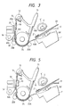
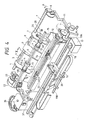
- Fig. 2 is a schematic perspective view of the printer shown in Fig. 1, without the outer casing.
- Fig. 3 is a schematic cross-sectional side view along a line X-X in Fig. 2.
- sliders, 1, 1′ constituting a part of a recording medium storing unit are slidably provided on a slider shaft 7, and are regulated in position corresponding to the width of the recording medium 33.
- Separating claws 2, 2′ respectively provided on sliders 1, 1′ separate the recording media 33 one by one in cooperation with separating rollers 4, 4′.
- Pressure plates 3, 3′, constituting the bottom of the recording medium storing unit are rotatably supported at an end thereof by shafts 1A respectively provided on the sliders 1, 1′, and are biased upwards by push-up springs 3A,3A′ about said shafts 1A,1A′,thereby enabling appropriate engagement of a separating roller shaft to be explained later and the recording media 33, regardless of the quantity thereof.
- separating roller 4 link member 5 and connecting members 5A, 5B are integrally combined and are rendered slidable along the slider shaft 7 and the separating roller shaft 6.
- the separating roller 4′, link members 5′ and connecting members 5A′, 5B′ are similarly integrated.
- a lever 8 is provided at an end of the slider shaft 7 for rotating the same.
- Pressure plate pressing arms 9, 9′ are fixed on the slider shaft 7 for respective engagement with the pressure plates 3, 3′, and rotate said pressure plates 3, 3′ anticlockwise about the shafts 1A in response to rotation in a direction A′ of the slider shaft 7.
- the lever 8 is rotated in a direction A′ by the actuation of the sheet set lever 103 mentioned above, whereby the arms 9, 9′ depress the pressure plates 3, 3′ against the biasing force of the springs 3A, 3A′. Consequently the pressure plates 3, 3′ are respectively disengaged from the separating claws 2, 2′, thereby facilitating the loading of the recording media 33.
- An automatic sheet feed (ASF) motor 22 is coupled with an end of the separating roller shaft 6 through a transmission mechanism 23.
- the rotation of said ASF motor 22 is transmitted, through the transmission mechanism 23, to the separating roller shaft 6, whereby the separating rollers 4, 4′ are rotated clockwise to separate and forward the recording media 33 one by one toward the sheet path in cooperation with the separating claws 2, 2′.
- a sheet feed roller 24 is provided at a suitable position to which the recording media 33 is supplied by the separating rollers 4, 4′.
- Sheet guide members 10A, 10B are positioned substantially along the periphery of the sheet feed roller 24, with a gap therebetween, from an entrance position of the recording medium from the sliders 1 to a platen 12, and the gap formed by said sheet guide members 10A, 10B constitutes the path for the recording medium 33.
- a sheet press member 10C defines the movement of the recording medium 33 and maintains it in contact with the platen 12.
- Pinch rollers 25A, 25B are positioned in two points around the periphery of the sheet feed roller 24 and are maintained in contact with the sheet feed roller 24 through apertures provided in the sheet guide members 10A, 10B. They are biased by unrepresented springs and press the recording medium 33, supported inside the sheet guide members 10A, 10B, toward the sheet feed roller 24.
- a sheet feed motor 11 is coupled to an end of the sheet feed roller 24 through a transmission mechanism 27.
- the rotation of said motor is transmitted through the transmission mechanism 27 to the sheet feed roller 24 which is thus rotated to advance the recording medium 33.
- a fixing heater 50 is mounted on a face of the platen 12 opposite to the face thereof contacting the recording medium 33.
- the fixing heater 50 heats the platen 12, of which heat is transmitted to the recording medium 33 thereby drying the recording medium 33 itself or the ink thereon after recording.
- a recording head 20 is provided with nozzles, constituting ink emitting orifices, in opposed position to the recording face of the recording medium 33 defined in position by the platen 12.
- nozzles constituting ink emitting orifices
- electrothermal converting elements for generating thermal energy or electromechanical converting elements for generating mechanical vibration energy.
- thermal energy is applied to the ink in response to the drive signals, thereby causing a state change in the ink and inducing ink emission from the orifices at the end of the ink paths.
- Such recording head there is preferred the use of such recording head.
- a recording head which is integral with an ink tank and is detachably mounted on the carriage, or a full-line recording head having the width of a line.
- a carriage 16, supporting the recording head 20, is fixed to a driving belt 18 and is rendered slidable on two guide shafts 19A, 19B positioned parallel to the platen 12, whereby the recording head 20 can reciprocate over the entire width of the recording sheet 33.
- a head driving motor 17 is provided in the vicinity of an end of the reciprocating path of the recording head 20 and is provided with a driving pulley 17A. Another pulley 17B is positioned at the other end of the reciprocating path of the head 20, and the belt 18 is supported by said pulleys 17A, 17B. The rotation of the head driving motor 17 is converted into linear motion by the belt 18 and is transmitted to the carriage 16 coupled with said belt 18, whereby the recording head 20 can reciprocate in the transversal direction of the recording medium 33.
- a head recovery device 26 is provided at an end of the moving path of the recording head 20 outside the recording range, for example at a home position, and can perform a capping operation for protecting the recording head 20 with a cap member 26A, and an operation of retracting said cap member from the moving path of the recording head 20, in response to the function of the ASF motor 22, through a suitable structure of the transmission mechanism 23. Simultaneous with the capping of the recording head 20 with the head recovery device 26, there can be conducted an emission recovering operation, for example by forced removal of the viscous ink from the nozzles, by means of ink suction with suitable suction provided in the head recovery device 26 or ink pressurizing with suitable pressurizing means provided in the ink paths to the recording head 20. Also at the end of the recording operation, the recording head can be protected by said capping.
- a wiper member 21 composed of a silicone rubber blade is provided on a lateral face of the head recovery device 26 so as to be engageable with the emission surface of the recording head 20, and engages with or is disengaged from the recording head 20 in response to the function of the ASF motor 22, again through a suitable structure of the transmission mechanism 23.
- said blade 31 is made to protrude in the moving path of the recording head 20, thus wiping off the ink overflowing from the nozzles, in the course of reciprocating motion of the recording head 20.
- the mechanism for separating and feeding the recording media 33, the structure of the transmission mechanism 23 for effecting the capping and wiping operation with a single motor 22, and the structure for effecting the separating and feeding of recording media and the driving of a pump provided as suction means for generating a negative pressure in the head recovery device 26 by means of a single motor, can relay on the structure disclosed by the present application for example in the Japanese Patent Applications 61-81637 and 61-197201.
- a humidity sensor 30, for detecting the humidity in the recording zone at the upstream side of the recording head in the sheet path, is provided on the sheet guide 10B extended to below the platen 12, in the vicinity of the recording zone.
- Figs. 4 and 5 are respectively a schematic perspective view and a schematic cross-sectional views of a printer in which the humidity sensor is positioned on a part of the platen in the vicinity of the recording zone, wherein same components as those in Figs. 2 and 3 are represented by same numbers and will not be explained further according to second preferred embodiment.
- the humidity sensor 30 is embedded in the platen 12, at a position corresponding to the orifices of the recording head.
- Fig. 6 is a schematic perspective view of a printer in which the humidity sensor is provided on the carriage, as a part of the recording zone.
- same components as those in Fig. 2 are represented by same numbers and will not be explained further.
- the humidity sensor 30 is not limited in its position but can be located at any position where the humidity can be detected. However, it is preferable for further excellent embodiment, as explained in the foregoing example, to place said sensor in the vicinity of the recording zone where the emitted ink is deposited on the recording medium.
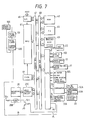
- Fig. 7 is a block diagram of a control system for use in the printer of each embodiment shown in Figs. 1 to 6.
- a microprocessing unit (MPU) 61 for controlling the entire printer; a read-only memory (ROM) 62 for storing control sequences of the printer, including those shown in Figs. 11 to 14; a random access memory (RAM) 63 having a buffer area for temporarily storing the image information to be recorded, a work area for control, and a flag area to be explained later; a character generator (CG) 64 for storing characters corresponding to character data; an input/output interface (I/O) 65 for data exchange with a host computer; an input/output interface (I/O) for data exchange with various sensors, motors and with the operation panel; a timer 69 for generating various timing signals such as those for the motors employed in the printer; and a head control circuit 20C for controlling the function of the recording head 20.
- the above-mentioned components 62 - 66, 69 and 20C are connected to the MPU 61 through an address bus 67, and are mutually connected by a data bus
- sensors 105 for detecting, for example, absence of sheets, absence of ink, width of recording sheet, presence of the recording head 20 at the home position etc.; a fixing heater thermistor 50A for detecting the temperature of the fixing heater 50; a head thermistor 20A for detecting the temperature of the recording head 20; and a comparator 70 for converting the temperature data from said thermistors 50A, 20A into binary signals utilizing predetermined temperatures as the threshold values.
- a humidity detecting circuit 30A is connected to the humidity sensor 30 for detecting the humidity of the recording zone, and has two signal line l2, l3 connected to the I/O 66.
- a transistor Trl is turned on by the logic level "1" of a signal line l4 connected to the I/O 66 to supply a positive temperature property thermistor 20B of positive characteristic with a current, thereby elevating the temperature of the recording head 20.
- a fixing heater control circuit 50B is controlled by the logic signal on a signal line l1 connected with the I/O 66, whereby the temperature of the fixing heater 50 is controlled by the power from an AC power source 106.
- the I/O 66 is connected, through signal lines other than the above-mentioned ones l1 - l4, with the ASF motor 22, operation panel 102, head driving motor 17, sheet feed motor 11, sensors 105 and comparator 70.
- Fig. 8 shows the details of the humidity detecting circuit shown in Fig. 7, wherein provided are an oscillator H1, a capacitor HC, a reference resistor HR, an amplifier H2, a rectifier H3, and comparators H4, H5.
- the aforementioned humidity sensor 30 varies the resistance according to the humidity.
- An AC voltage generated by the oscillator HL and the capacitor HC is applied to a serial circuit of the reference resistor HR and the humidity sensor 30, and the voltage divided by the reference resistor HR is amplified and converted into a DC voltage by the amplifier H2 and the rectifier H3. Said DC voltage is compared with predetermined voltages in the comparator H4 or H5, and varies the logic signals in the signal lines l2, l3.
- the resistances connected to the circuit are suitable selected in such a manner that the signal in the line l2 assumes a level “1” or “0” respectively when the humidity detected by the humidity sensor 30 is above or below a predetermined value, for example 80%, and that the signal in the line l3 assumes a level “1” or “0” respectively when the detected humidity is above or below, for example, 50%.
- a logic level “1" of the line l2 indicates a high humidity
- a logic level “0" of the line l3 indicates a low humidity
- Fig. 9 shows the details of the fixing heater control circuit shown in Fig. 7, wherein provided are a transistor Tr2, a photocoupler T1, a bidirectional three-terminal thyristor T3, and a fixing heater 50 mentioned above.
- the signal line l1 assumes a logic level "1" under the control of the MPU 61 through the I/O 66
- the transistor Tr2 is turned on to emit light from the light-emitting element of the photocoupler T1, whereby the photosensor thereof generates a current which is supplied to the gate electrode of the bidirectional three-terminal thyristor T3.
- Fig. 10 is a circuit diagram of a dew detecting circuit constituting one of humidity detecting means, wherein shown are a dew sensor 30′, and comparators K1, K2. A voltage obtained by dividing a reference voltage Vcc with the resistance of the dew sensor 30′ is supplied to terminals of the comparators K1, K2.
- the dew sensor 30′ is a kind of humidity sensor, and rapidly increases the resistance thereof when the relative humidity approaches to 100%. For example it shows a switching-like change in resistance at a relative humidity 94%.
- Divided voltages of the reference voltage, supplied to the other terminals of the comparators K1, K2 are suitably selected with resistances in such a manner that the comparator K1 releases a logic signal "1" to the signal line l2, when the relative humidity is close to 100%, namely when the dewing is going to occur.
- the dew sensor may be employed instead of the humidity sensor 30 explained before.
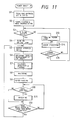
- Fig. 11 is a flow chart showing the sequence of function or processing various parts of the aboveexplained printer.
- a step S1 executes initializing and checking of the printer 100, including the clearing of the flags and counters in the RAM 63, and the checking of I/O ports. Then a step S2 turns on the head thermistor 20B and the fixing heater control circuit thereby heating the fixing heater 50 and the recording head 20.
- a step S3 discriminates whether a recording medium 33 is present in the recording range. If not, the sequence proceeds to a step S13 to turn on a paper lamp on the operation panel 102, thereby giving a warning for the absence of recording sheet. Then a step S14 executes an error process such as the feeding of recording media 33 or transportation of the recording medium 33 to the recording zone, and a step S15 discriminates whether the error of absence of recording sheet has been resolved. If resolved, the sequence returns to the step S3.
- a step S4 makes an on-line state with the host computer, and turns on an on-line lamp on the operation panel 102. Then a step S5 releases a signal to shift the Busy signal to a logic level "0" thereby enabling data reception from the host computer.
- a next step S6 receives the image data to be recorded and develops a dot image of each scanning line in the RAM 63.
- a step S7 executes a process of humidity detection and control of the present invention, which will be explained later in relation to Fig. 12.
- a step S8 activates the heat drive motor 17 and the energy generating means of the recording head 20, thereby effecting start of the carriage 16 from the home position, recording in a predetermined range, returning of the carriage 16 to the home position, and stopping at a predetermined position.
- a step S9 advances the recording medium 33.
- steps S10 and S11 may receive the image data from the host computer.
- a step S12 then discriminates whether the head drive motor 17 and the sheet feed motor 11 have been stopped. Recording of a line is completed through the above-explained sequence.
- the above-explained steps execute the recording of a scanning line and the related processes, and the sequence returns to the step S5 when the discrimination in the step S12 turns out affirmative.
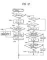
- Fig. 12 is a flow chart showing the details of humidity detection and control, shown in the step S7 in Fig. 11.
- a step S701 discriminates whether the recording zone is in a high humidity state, for example exceeding 80%, by checking the logic level of the signal line l2, and, if it is "1" indicating the high humidity state, the sequence proceeds to a step S702 to shift the logic level of the signal line l1 to "0" thereby terminating the heating of the fixing heater 50.
- a step S703 discriminates whether the recording head 20 has been adjusted to a high temperature for the high humidity state, and, if not, a step S704-1 shifts the signal line l4 to a logic level "1", thereby turning on the thermistor 20B of positive characteristics and heating the recording head 20.
- the dewing of the head 20 is thus prevented by terminating the heating of the heater 50 thereby reducing the water evaporation from the recording medium and lowering the humidity, and by elevating the temperature of the recording head 20 thereby reducing the temperature difference.
- the recording head 20 has an upper limit temperature for the ink emission etc.
- the sequence proceeds to a step S704 to shift the signal line l4 to a logic level "0", thereby turning off the thermistor 208 and terminating the heating of the head 20.
- the sequence proceeds to a step S705 to set a flag to "1", indicating that a high humidity state has existed at least immediately before in the recoridng zone. The routine of humidity detection and control is thus terminated.
- a step S706 discriminates if the flag is in a state "1". If it is "1", indicating the presence of a high humidity state immediately before, a step S707 discriminates whether the humidity has been lowered, by checking the state of the signal line l3. If it is "1", indicating that a predetermined humidity, for example less than 50%, has not been reached, the sequence proceeds to the step S703 to effect the above-explained process for lowering the humidity under the temperature control of the head, and the routine of humidity detection and control is thus terminated.
- step S707 determines whether the discrimination in the step S707 turns out negative, indicating a low humidity state in the recording zone. If the discrimination in the step S707 turns out negative, indicating a low humidity state in the recording zone, the sequence proceeds to a step S708 for resetting the flag to "0" and to a step S709 for entering the normal operation. Also if the discrimination in the step S706 turns out negative, indicating the absence of the high humidity state immediately before, the sequence proceeds to the step S709.
- steps S709 and S710 or S709 and S711 execute ordinary heater temperature setting. More specifically, the step S709 discriminates whether the heater temperature is higher or lower than a predetermined temperature, for example 75°C, and, if lower, the step S710 shifts the signal line l1 to a logic level "1" to activate the fixing heater 50, or, if higher, the step S711 shifts the signal line l1 to "0" thereby deactivating the fixing heater 50.
- a predetermined temperature for example 75°C
- steps S712 and S713 or S714 execute ordinary temperature control of the recording head.
- the step S712 discriminates whether the temperature of the head 20 is higher or lower than a predetermined temperature, for example 30°C, and, if higher, the step S713 shifts the signal line l4 to "0" to terminate the heating of the head 20, or, if lower, the step S714 shifts the signal line l4 to "1" to turn on the thermistor 20B thereby heating the head 20. In this manner the routine of humidity detection and control is terminated.
- a predetermined temperature for example 30°C
- Fig. 13 is a flow chart for the dew detection and control in the step S7 in Fig. 11, in case the dew sensor shown in Fig. 10 is employed.
- the signal line l2 for sending the high humidity signal is replaced by a signal line l2′ for sending a signal representing a dew state.
- a step S801 discriminates whether the head 20 is in a dewing state by checking the state of said signal line l2′, and, if it is in a logic level "1" indicating that the head 20 is already in a dewing state or close to such state, a step S802 shifts the signal line l1 to a logic state "0" to deactivate the fixing heater 50. Then a step S803 discriminates whether the recording head 20 has been regulated to a predetermined high temperature in the dew state, and, if not, a step S804-1 shifts the signal line l4 to a logic level "1" thereby heating the recording head 20.
- the dewing of the head 20 is reduced by lowering the temperature of the heater 50 thereby reducing the moisture evaporation from the recording medium and reducing the humidity, and by elevating the temperature of the head 20.
- the recording head 20 has an upper limit temperature for ink emission. Therefore, when the high predetermined temperature is reached, the signal line l4 is shifted to a logic level "0" to turn off the thermistor 20B, thereby terminating the heating of the head 20.
- a sequence starting from a step S805 executes ordinary temperature setting of the heater 50 and the recording head 20.
- steps S805 and S806 or S807 execute ordinary heater temperature setting.
- the step S805 discriminates whether the heater 50 is higher or lower than a predetermined temperature, and, if lower, the step S806 shifts the signal line l1 to a logic level "1" to activate the fixing heater 50, or, if higher, the step S807 shifts said signal line l1 to "0" thereby deactivating the fixing heater 50.
- steps S808 and S809 or S810 execute ordinary temperature control for the recording head 20.
- the step S808 discriminates whether the temperature of the head 20 is higher or lower than a predetermined temperature, and, if higher, the step S809 shifts the signal line l4 to a logic level "0" thereby terminating the heating of the head 20, or, if lower, the step S810 shifts the signal line l4 to a logic level "1" to turn on the thermistor 20B, thereby heating the head 20. In this manner the routine of dew detection and control is terminated.
- Fig. 14 is a flow chart in which the routine of humidity detection and control is included, as a step S23, in the recording of a scanning line shown by the setp S8 in Fig. 11.
- a step S21 activates the head driving motor 17, and a step S22 awaits the movement of the recording head 20 to the recording position.
- a step S23 executes the above-mentioned routine of humidity detection and control, and a step S24 simultaneously executes recording by releasing the dot image from the buffer area of the RAM 63.
- the sequence is terminated upon detection, in a step S25, of the movement of the head 20 to a recording end position.
- Fig. 15 is a flow chart showing humidity detection and control different from the process shown in Fig. 12.
- a step S903 discriminates whether the temperature of the fixing heater 50 is higher or lower than a predetermined low temperature, and, if higher, a step S904 deactivates the heater 50, or, if lower, a step S905 activates the heater 50.
- the low temperature state of the heater 50 may be controlled in plural levels according to the result of detection by the sensor.
- a fourth embodiment of the present invention which is same, in the basic structure, as the first to third embodiment, except for the use of plural fixing heaters and a circuit for suitably driving said plural fixing heaters as shown in Fig. 16, in which same components as those in Fig. 3 will be omitted from the following explanation.
- fixing heaters 51, 52 are mounted on a face of the platen 12, made of metal, rubber or plastics, opposite to the face contacting the recording sheet 33. Said fixing heaters 51, 52 heat the platen 12, of which heat is transmitted to the recording medium 31 for drying said medium itself or the ink thereon.
- the heater 52 is designed to heat the recording medium 33 prior to recording, and the heater 51 is designed to heat it after recording.
- the position of the humidity sensor is not limited also in the present fourth embodiment so far as the object of the present invention is achieved, but it is preferably positioned in the vicinity of the recording zone as in the first to third embodiments.
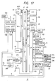
- Fig. 17 is a block diagram of the control system in the fourth embodiment, which is in basic structure similar to that shown in Fig. 7.
- FIG. 17 there are shown fixing heater thermistors 51A, 52A for detecting the temperatures of fixing heaters 51, 52; a head thermistor 20A for detecting the temperature of the recording head 20; and a comparator 70 for converting the temperature data from said thermistors 51A, 52A into binary signals, utilizing predetermined temperatures as threshold values.
- Fixing heater control circuits 51B, 52B to be explained later in relation to Fig. 18 are controlled by the logic signal of a signal line l1 connected to the I/O 66, whereby the temperatures of the fixing heaters 51, 52 are controlled under the power supply from the AC power source 106.
- the I/O 66 is connected, through signal lines other than l1 - l4 and l7, to the ASF motor 22, operation panel 102, head drive motor 17, sheet feed motor 11, sensors 105 and comparator 70.
- Fig. 18 shows the details of the fixing heater control circuit shown in Fig. 17, which is basically similar to that shown in Fig. 9.
- a transistor Tr2 a photocoupler T1 a bidirectional three-terminal thyristor T3, and fixing heater 51 (52) explained above.
- the signal line l1 (l7) is brought to a logic level "1" under the control of the MPU 61 through the I/O 66, the transistor Tr2 is turned on to emit light from the light-emitting element of the photocoupler T1, whereby the photosensor of the photo- coupler T1 sends a current to the gate electrode of the bidirectional three-terminal thyristor T3.
- the thyristor T3 transmits the AC power to the fixing heater 51 (52) to raise the temperature thereof.
- the humidity detecting circuit or the dew detecting circuit can be similar to that shown in Fig. 8 or 10, and will not, therefore, be explained further.
- step S2 drives plural fixing heaters. More specifically the step S2 turns on the thermistor 20B for the head 20 and the fixing heater control circuits 51B, 52B, thereby heating the fixing heaters 51, 52 and the recording head 20.
- Fig. 19 is a flow chart showing the details of the routine of humidity detection and control in the fourth embodiment, corresponding to the step S7 in Fig. 11.
- a step S1701 discriminates whether the recording zone is in a high humidity state, by checking the logic level of the signal line l2, and, if it is "1" indicating the high humidity state, for example higher than 80%, the sequence proceeds to a step S1702 to shift the logic level of the signal line l1 to "0" thereby terminating the heating of the fixing heater 52. In this manner the moisture evaporation from the recording medium prior to recording is reduced, and the humidity in the recording zone is lowered.
- a step S1703 sets the flag to "1", indicating that a high humidity state has existed at least immediately before in the recording zone. Then a step S1704 discriminates the lapse of a predetermined period. If the high humidity state continues for the predetermined period, a next step S1705 shifts the signal line l7 to a logic level "0" thereby deactivating the heater 51. Thus the moisture evaporation from the recording medium is furhter lowered by the deactivation of the heater 51, in addition to the heater 52.
- the routine of humidity detection and control is terminated after the process of the step S1705, or if the discrimination of the step S1704 turns out negative.
- step S1701 If the discrimination of the step S1701 turns out negative, indicating the absence of the high humidity state in the recording zone, the sequence proceeds to a step S1706 for discriminating the state of the flag. If it is "1", indicating the presence of high humidity state immediately before, a step S1707 checks the logic level of the signal line l3, thereby discriminating whether a low humidity state has been reached. If it is "1", indicating that a predetermined humidity, for example 50%, has not yet been reached, the routine of humidity detection and control is terminated in order to await the lowering of the humidity.
- step S1707 If the discrimination of the step S1707 turns out negative, indicating a low humidity state in the recording zone, a step S1708 resets the flag to "0", and the sequence proceeds to a step S1709. Also if the discrimination in the step S1706 is negative, indicating the absence of the high humidity state immediately before, the sequence proceeds likewise to the step S1707.
- steps S1709 and S1710 or S1711 execute ordinary temperature setting for the heater 52.
- the step S1709 discriminates whether the temperature of the heater 52 is higher or lower than a predetermined ordinary temperature, and, if higher, the step S1711 shifts the signal line l1 to a logic level "0", thereby deactivating the heater 52, or, if lower, the step S1710 shifts said signal line to a logic level "1" thereby activating the heater 52.
- steps S1712 and S1713 or S1714 execute ordinary temperature setting for the heater 51 in a similar manner as in the heater 52, and the routine of humidity detection and control is terminated.
- Fig. 20 is a flow chart for the dew detection and control in the step S7 in Fig. 11, in case the humidity sensor in the fourth embodiment is replaced by a dew sensor as shown in Fig. 10.
- the signal line l2 for sending the high humidity signal is replaced by a signal line l2′ for sending a signal representing a dewing state.
- a step S1801 discriminates whether the head 20 is in a dewing state by checking the state of said signal line l2′, and, if it is in a logic level "1" indicating that the head 20 is already in a dewing state or close to such state, a step S1802 shifts the signal line l1, as the step S702 shown in Fig. 19, to a logic state "0" to deactivate the heater 52. Then steps S1803 and S1804 execute a process similar to the steps S1704 and S1705 shown in Fig. 19.
- step S1801 If the discrimination in the step S1801 turns out negative, indicating the absence of dewing, the sequence proceeds to steps S1805 to S1810 for executing a process similar to that in the steps S1709 - S1714 shown in Fig. 19, for ordinary temperature setting for the heaters 52 and 51.
- the ordinary temperature setting of the heater 52 causes moisture evaporation from the recording medium prior to recording, thereby improving the image fixation thereon and reducing the amount of moisture evaporation in the recording zone, thus lowering the humidity therein.
- Fig. 21 is a flow chart showing an example of humidity detection and control of the process different from one shown in Fig. 19.
- steps S1903 to S1908 control the heater 51 is similar manner.
- the low temperature state of the heaters 51, 52 may be controlled in plural levels according to the result of detection by the sensor.
- a fifth embodiment of the present invention which is same, in the basic structure, as the first, second or third embodiment but is different in the use of a humidity sensor for detecting the humidity outside the apparatus, in addition of the humidity sensor in the foregoing embodiments.
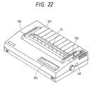
- Fig. 22 shows the external view of the printer
- Fig. 23 shows the principal structure thereof.
- an external humidity sensor 40 is provided on a lateral face of the main body 100, for the temperature control of the fixing device according to the present invnetion will be explained later.
- the sensor 40 is not limited in its position, and may be provided in another position, for example in the front face or the rear face of the apparatus.
- Fig. 24 is a block diagram of the control system of the printer of the present embodiment, which is same, in basic structure, as than shown in Fig. 7.
- Humidity detecting circuits 30A, 40A are respectively connected to the humidity sensor 30 for detecting the humidity of the recording zone and a humidity sensor 40 for detecting the external humidity, and respectively have signal lines l2, l3 and l5, l6 connected to the I/O 66.
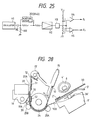
- Fig. 25 shows the details of the humidity detecting circuit shown in Fig. 24, wherein provided are an oscillator H1; a capacitor HC; a reference resistor HR; an amplifier H2; a rectifier H3; comparators H4, H5; and above-mentioned humidity sensors 30, 40 varying the resistance according to the humidity.
- An AC voltage generated by the oscillator H1 and the capacitor HC is supplied to a serial circuit composed of the reference resistor HR and the humidity sensor 30 (40), and the voltage divided by the reference resistor HR is amplified and converted into a DC voltage by the amplifier H2 and the rectifier H3.
- the obtained DC voltage is compared with a predetermined voltage with the comparator H4 or H5, and varies the logic signal of the signal line l2 or l5 or l3 or l6.
- the resistances connected to the circuits are suitably selected in such a manner that the signal lines l2, l5 assume a logic level “1” or “0” respectively when the humidity detected by the sensor 30 or 40 is above or below a predetermiend value, for example 80%, and that the signal lines l3, l6 assume a logic level "1” or "0” respectively when the detected humidity is above or below, for example, 50%.
- a circuit shown in Fig. 9 may be employed as the fixing heater control circuit. Also the control sequence for various components of the printer can be same as that shown in Fig. 11.
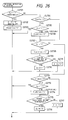
- Fig. 26 is a flow chart showing the details of the process of humidity detection and control shown in the step S7 in Fig. 11.
- a step S2701 discriminates whether the recording zone is in a high humidity state, by checking the logic level of the signal line l2, and, if it is "1" indicating the high humidity state, for example higher than 80%, the sequence proceeds to a step S2702 to shift the logic level of the signal line l1 to "0" thereby terminating the heating of the fixing heater 50 and reducing the moisture evaporation from the recording medium. Then a step S2703 sets a flag FLAG1 to "1", indicating that a high humidity state has existed at least immediately before in the recording zone. The routine of humidity detection and control is thus terminated.
- a step S2704 discriminates if the flag FLAG1 is in a state "1′. If it is "1", indicating the presence of a high humidity state immediately before, a step S2705 discriminates whether the humidity has been lowered, by checking the state of the signal line l3. If it is "1", indicating that a predetermined humidity, for example 50% or less, has not been reached, the above-explained flow for reducing the humidity is continued, and the process of humidity detection and control is terminated.
- step S2705 determines whether the discrimination in the step S2705 turns out negative, indicating a low humidity state in the recording zone. If the discrimination in the step S2704 turns out negative, indicating the absence of high humidity state immediately before in the recording zone, the sequence likewise proceeds to the step S2707.
- the step S2707 discriminates whether the external atmosphere of the printer 100 is in a high humidity state, for example 80%, by checking the logic level of the signal line l2. If it is "1", indicating the high humidity state of the external atmosphere, a step S2708 sets a falg FLAG2 to "1", indicating the presence of a high humidity state of external atmosphere at least immediately before, as in the flag FLAG1.
- steps S2709 and S2710 or S2711 execute a process for setting the heater 50 at a temperature higher than the ordinary set temperature.
- the step S2709 discriminates whether the heater temperature is higher or lower than the predetermined high temperature, and, if lower, a step S2710 activates the heater 50, or, if higher, a step S2711 deactivates the heater 50.
- the step S2707 identifies a high external humidity, the temperature of the heater 50 is selected higher than in the ordinary state, in order to accelerate the fixation of the recorded image.
- a step S2712 discriminates the state of the flag FLAG2. If it is "1”, a step S2713 discriminates whether the external humidity has been lowered to a predetermined humidity, by checking the logic level of the signal line l6. If it is "1", indicating that the external humidity has not yet been lowered to the predetermined humidity level, the routine of humidity detection and control is terminated, in order to wait for the lowering of the external humidity.
- step S2715 if the external atmosphere is in a low humidity state, below a predetermined level, the flag FLAG2 is reset to "0", and the sequence proceeds to a step S2715. Also if the discrimination in the step S2712 turns out negative, the sequence proceeds to the step S2715.
- Steps S2715 and S2716 or S2717 execute a process of setting the heater 50 at an ordinary set temperature.
- the step S2715 discriminates whether the temperature of the heater 50 is higher or lower than the ordinary set temperature, and, if higher, the step S2716 deactivates the heater 50, or, if lower, the step S2717 activates the heater 50.
- the routine of humidity detection and control is terminated in this manner.
- the above-explained routine for humidity detection and control is conducted for each recording of a scanning line, as shown in Fig. 10, thus controlling the temperature of the heater 50 according to the humidity in the external atmosphere and in the internal recording zone. In this manner the recorded image can be appropriately fixed, while the recording head is maintained in a dew-free state.
- the above-explained routine for humidity detection and control may be included in the recording operation of a scanning line, as shown in Fig. 14.
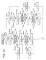
- Fig. 27 is a flow chart showing embodiment of the process for humidity detection and control different from shown in Fig. 26.
- a step S2803 discriminates whether the temperature of the fixing heater 50 is higher or lower than a predertermined low temperature, and, if higher, a step S2804 deactivates the heater 50, or, if lower, a step S2805 activates the heater 50.
- the low temperature state of the heater 50 may be controlled in plural levels according to the result of detection by the sensors.
- Fig. 28 schematically shows side sectional view of an ink jet recording apparatus of a seventh embodiment of the presetn invention, which is same, in basic structure, as the foregoing embodiments but is different in that the recording head is integrally constructed with an ink tank and is rendered detachable from the carriage, and in the use of two humidity sensors and two fixing heaters, namely a first humidity sensor for detecting the humidity in the apparatus, a second humidity sensor for detecting the humidity in the external atmosphere, a first heater for heating the recording medium prior to recording, and a second heater for heating said medium after recording, for achieving finer control.
- two humidity sensors and two fixing heaters namely a first humidity sensor for detecting the humidity in the apparatus, a second humidity sensor for detecting the humidity in the external atmosphere, a first heater for heating the recording medium prior to recording, and a second heater for heating said medium after recording, for achieving finer control.
- the control function in the present embodiment is summarized in the following table: 1st humidity sensor high humid. high humid. low humid. low humid. low humid 2nd humidity sensor high humid. low humid. high humid. low humid. 1st heater stop or low temp. stop low or high temp. stop or low temp. 2nd heater stop or low temp. Low temp. high temp. Low or high temp. recording head high temp. high temp. low temp. low temp.
- the blade 31 shown in Fig. 2 is suitable for wiping off the overflowing ink from the orifices, caused for example in the suction form the orifices with the head recovery device 26 or by the vibration of head 20 at the end of the reciprocating stroke thereof, or the water drops generated by dewing, but repeated bladings may damage the emission surface, giving rise to an undesirable effect on the ink droplet emission.
- Such situation becomes a particular problem when the recording head 20 is formed by combining plurality of members made of different materials and is subjected to a liquid-repellent treatment for obtaining uniform wetting on the emission surface (as disclosed by the present applicant in the Japanese Patent Applications 61-268493 - 61-248500).
- the dewing on the emission surface is eliminated or significantly reduced, so that the wiping operations can be dispensed with or at least reduced in number.
- the present invention is to control the temperatures of the recording head and the fixing heater, according to the humidity in the vicinity of the recording zone.
- the present invention enables separate heating of the recording medium prior to and after the recording, under suitable temperature control.
- the image fixation can be accelerated as the moisture in the recording medium can be evaporated prior to the image recording.
- the present invention further enables appropriate temperature control of the fixing heater, depending on the humidity in the recording zone and in the external atmosphere.
Abstract
a recording head (20) for image recording by ink emission into a recording medium (33);
heater means (50) for heating said recording medium;
humidity detector means (30) for detecting the humidity in the vicinity of a recording zone formed by said recording head and said recording medium; and
control means for controlling the heating temperature of said heater means according to the humidity detected by said humidity detector means.
Description
- The present invention relates to an ink jet recording apparatus, and more particularly to an ink jet recording apparatus provided with a fixing heater for accelerating fixation of the ink deposited as a recorded image on a recording medium.
- The ink jet recording apparatus are attaching increasing attention in the field of recording apparatus, because of various advantages such as very low noise level at the recording and capability of a high density recording.
- Also the ink jet recording apparatus have an advantage that it can use plain paper as the recording medium, but the fixation of the ink on a recording paper may be difficult depending on the combination of the recording sheet to be employed and the ink. Since the ink jet recording apparatus employs liquid ink as the recording material, the ink may not penetrate rapidly into the recording medium and remain in liquid state thereon if the recording medium shows insufficient absorption to the ink.
- In such situation there may result smear of the transport members such as rollers, and said smear may be transferred to the succeeding recording medium, thereby significantly deteriorating the quality of recording. Also, in case of using a recorded sheet on which the ink is not sufficiently fixed, not only a problem of smearing hands of the operator but also a problem of ink spreading of ink due to erroneously rubbing the image would be caused. Thus, the image quality is deteriorated. Such drawback of smearing and spreading may also occur due to the mutual friction of the recorded media in case that the recorded media are stacked on a discharge tray.
- In order to prevent such drawbacks and to facilitate the fixation of ink to the recording medium, there has been proposed to heat the recording medium with a heater, thereby accelerating the evaporation of water contained in the ink and rapidly drying the ink on the recording medium. For the purpose of shortening the transport path of the recording medium and preventing the smear on the transport members, such fixing heater is provided in the vicinity of the recording position of the recording head, for example in a platen for supporting the recording medium so that its recording surface would be flat in front of the recording head. Also said heater may be positioned at the upstream side of said recording position in the transport path for pre-heating the recording medium, since the ink absorption is enhanced if the recording medium is dried in advance.
- The deterioration of the recorded image quality may also be caused by dewing in the ink jet recording apparatus. Under certain circumferential conditions the moisture condensed by dewing in the apparatus may adhere to the recording medium, causing ink blotting. Such problems resulting from dewing cannot be prevented by the use of a fixing heater.
- In order to prevent such dewing, the present inventors have noticed, in a different technical area, the electrophotographic technology, and have considered application of a dew-preventing device employed in electrophotographic copying machines to the ink jet recording apparatus. For example, they tried a method of controlling a heating operation of plurality of heaters provided respectively for plurality of temperature sensors, single humidity sensor, paper feeding section, optical unit and fixing unit as described in Japanese Patent-Laid-Open No.55-35390, and a method of removing moisture by blower as described Japanese Patent Laid Open No.56-80061 in addition to the above described heat control method.
- However, these methods involve certain obstacles to be simply applied to the ink jet recording apparatus, such as 1) that the apparatus inevitably becomes bulky because of the user of plural antidewing heaters in addition to the fixing heater, and 2) the viscosity of the ink is influenced by the heat from the antidewing heaters so that stability of recording property is lowered. Besides the experiments of the present inventors have revealed the cause and influence of dewing in the ink jet recording apparatus in the following manner.
- In the ink jet recording apparatus, rapid and satisfactory fixation without warping in the recording medium is generally achieved, according to the experiments of the present inventors, in a temperature range of the recording medium of 80° to 60°C.
- On the other hand, the recording head is maintained at 20° to 40°C in consideration of parameter influencing the stability of ink emission such as ink viscosity. This temperature is lower than the circumferential temperature.
- Under such conditions, the face of the ink emission orifices of the recording head (hereinafter called emission surface) may cause dewing, because a high humidity atmosphere is created around the recording, particularly in the vicinity of the emission surface, due to water evaporation from the recording medium and from the ink by heating for fixing.
- In the ink jet recording, it is generally important that the ink droplet is deposited at a desired position, in order to improve the image quality, and, for this purpose, it is required that the ink droplets for use in recording have constant flying direction and speed of emission with a uniform size.
- The dewing on the emisison surface, in particular, peripheral of emission orifice generates uneven water drops thereon at the peripheral of orifices, exerting random attraction to the ink droplets leaving the ink orifices and thus causing fluctuation in the direction and speed of emission of the ink droplets and in the size thereof. These facts lead to deterioration of the recorded image quality. Also the wet emission surface induces deposition of paper dusts and other dusts, which leads to the deterioration of recorded image quality.
- It has therefore been clarified that the dewing in the ink jet recording apparatus could only be resolved in careful consideration of the fixing temperature, temperature of recording head etc., considering result of extensive time of experiments.
- In consideration of the foregoing, an object of the present invention is to provide a method of preventing dewing in the ink jet recording apparatus, which minimizes the dewing on the emission surface and thus stabilizes the direction and speed of emission of ink droplets and the size thereof, thereby preventing deterioration of the recorded image quality, and an ink jet recording apparatus achieving such method.
- Another object of the present invention is to provide an ink jet recording apparatus provided with a recording head for emitting ink for image recording on a recording medium; heater means for heating the recording medium; humidity detector means for detecting the humidity in a recording zone formed by the recording head and the recording medium; and control means for controlling the temperature of the heater means according to the humidity detected by the humidity detector means.
- Still another object of the present invention is to provide an ink jet recording apparatus provided with first heater means for preheating recorded area of the recording medium prior to image recording; second heater means for heating the recording medium after recording thereby fixing the recorded image; humidity detector means for detecting the humidity in the vicinity of the zone of the recording medium is subjected to image recording; and control means for controlling the temperatures of the first and second heater means according to the humidity detected by the humidity detector means.
- Still another object of the present invention is to provide an ink jet recording apparatus with heater means for heating the recording medium for fixing the recorded image, provided with first humidity detector means for detecting the humidity of a zone in which the recording medium is subjected to image recording; second humidity detector means for detecting the ambient humidity outside the ink jet recording apparatus; and control means for controlling the temperature of the heater means according to the humidities detected by the first and second humidity detector means.
- In the above-mentioned structure it is rendered possible to control the heating temperatures of the recording head and the heating means for fixing at optimum level for the ink jet recording apparatus according to the humidity in the vicinity of recording zone, thereby preventing dewing, without additional dew preventing device.
- It is also possible to achieve image fixation without dewing, by appropriate temperature control of the recording medium before and after image recording.
- It is furthermore possible to achieve appropriate temperature control of the fixing heater without dewing, in response to the humidity levels in the recording zone and in the ambient atmosphere.
-
- Fig. 1 is a schematic perspective external view of an ink jet recording apparatus one preferred embodiment of the present invention;
- Figs. 2 and 3 are respectively schematic perspective and cross-sectional side views of the ink jet recording apparatus of Fig. 1, without outer casing;
- Figs. 4 and 5 are respectively schematic perspective and cross-sectional views of an ink jet printer in which a humidity sensor, shown in Figs. 1, 2, and 3, is provided on the platen of another preferred embodiment of the present invention;
- Fig. 6 is a schematic perspective view of ink jet printer in which the humidity sensor, shown in Figs. 1, 2 and 3, is provided instead on the carriage according to still another embodiment of the present invention;
- Fig. 7 is a block diagram of a control system of the ink jet printer of the present invention as shown in Figs. 1 - 6;
- Fig. 8 is a circuit diagram showing an example of a temperature detecting circuit to be employed in the present invention;
- Fig. 9 is a circuit diagram showing an example of a fixing heater control circuit to be employed in the present invention;
- Fig. 10 is a circuit diagram showing an example of a dew detecting circuit to be employed in the present invention;
- Fig. 11 is a flow chart showing an example of recording and ancillary processes of the ink jet printer of the present invention;
- Fig. 12 is a flow chart of an another example of humidity detection and control process of the present invention;
- Fig. 13 is a flow chart of an another example of dew detection and control process of the present invention;
- Fig. 14 is a flow chart in case the process shown in Fig. 11 is conducted during a recording operation;
- Fig. 15 is a flow chart showing humidity detection and control of the ink jet printer;
- Fig. 16 is a schematic cross-sectional view of the ink jet recording apparatus constituting another embodiment of the present invention;
- Fig. 17 is a block diagram of the control system the ink jet printer as shown in Fig. 16;
- Fig. 18 is a circuit diagram showing an example of the fixing heater control circuit to be employed in the ink jet printer as shown in Fig. 16;
- Fig. 19 is a flow chart showing an example of humidity detection and control process in the ink jet printer as shown in Fig. 16;
- Fig. 20 is a flow chart showing an example of dew detection and control process in the apparatus as shown in Fig. 16;
- Fig. 21 is a flow chart showing another example of humidity detection and control process of apparatus as shown in Fig. 16;
- Fig. 22 is a schematic external perspective view of an ink jet recording apparatus relating to still another embodiment of the present invention;
- Fig. 23 is a schematic perspective view of the ink jet recording apparatus shown in Fig. 22, without outer casing;
- Fig. 24 is a block diagram showing an exmaple of the control system for use in the ink jet recording apparatus as shown in Figs. 21 and 22;
- Fig. 25 is a circuit diagram showing an example of the humidity detecting circuit shown in Fig. 24;
- Fig. 26 is a flow chart showing an exmaple of humidity detection and control process as shown in Figs. 21 and 22;
- Fig. 27 is a flow chart showing an example of the process of humidity detection and control of apparatus as shown in Figs. 21 and 22; and
- Fig. 28 is a schematic cross-sectional side view of an ink jet recording apparatus constituting a sixth embodiment.
- In one of preferred embodiments of the present invention, the ink jet recording apparatus is equipped with at least one humidity detector means and at least one fixing heater means, wherein heating temperature of said heater means is varied according to the humidity detected by said humidity detector means. It is also preferred to suitably vary the temperature of the recording head itself. More specifically, (1) if a high humidity is detected by the humidity detector means, the heating by the heater means is interrupted or adjusted to a temperature lower than the normal fixing temperature, thereby preventing rapid humidity rise and thus avoiding dewing; or (2) in such situation temperature of the recording head itself is brought to a temperature higher than the normal heating temperature, thereby reducing dewing tendency thereon. Besides, the combination of the above-mentioned methods (1) and (2) reduces the temperature difference between temperature of the recording head and temperature of the atmosphere therearound, thus preventing the dewing on the recording head or reducing it so that substantially no adverse effect would be caused.
- The preferred temperature range for the heating means is not exceeding 80°C, more preferably from 60° to 80°C, and that temperature region the recording head itself is suitably selected according to a kind and property of ink to be used, 20° to 40°C is desirable for the region.
- Though a temperature higher or lower than the above-mentioned ranges may be suitably selected, the temperature selection within said ranges is nevertheless desirable.
- The present invention will now be clarified in greater detail by embodiments thereof shown in the attached drawings.
- Fig. 1 is a schematic external perspective view of an ink jet recording apparatus (hereinafter briefly called ink jet printer or printer) embodying the present invention, wherein shown are a
main body 100; a sheetdischarge guide member 15 constituting a part of a sheet discharge exit formed in the center of an upper cover of theprinter 100; and asheet discharge tray 101 formed in continuation to saiddischarge guide 15 and constituting a part of the upper cover, whereby a recording medium or sheet after image recording is discharged from themain body 100 while being guided by saiddischarge guide 15 and is placed on thetray 101. - An
operation panel 102 formed in a part of the upper cover is provided with input keys for various operations to be explained later and indicator lamps for indicating the operation status of the printer. A sheet setlever 103 emerging through an aperture at an end of the upper cover actuates a sheet feeding mechanism to be explained in relation to Figs. 2 and 3, for facilitating the sheet loading. - Fig. 2 is a schematic perspective view of the printer shown in Fig. 1, without the outer casing.
- Fig. 3 is a schematic cross-sectional side view along a line X-X in Fig. 2.
- In Figs. 2 and 3, sliders, 1, 1′ constituting a part of a recording medium storing unit are slidably provided on a
slider shaft 7, and are regulated in position corresponding to the width of therecording medium 33. Separatingclaws sliders recording media 33 one by one in cooperation with separatingrollers Pressure plates sliders springs recording media 33, regardless of the quantity thereof. -
Link members roller shaft 6, respectively support separatingrollers members sliders - Thus the separating
roller 4,link member 5 and connectingmembers slider shaft 7 and the separatingroller shaft 6. The separatingroller 4′,link members 5′ and connectingmembers 5A′, 5B′ are similarly integrated. - In the above-explained structure, when the
sliders recording medium 33, the separatingrollers roller shaft 6. Also thepressure plates claws sliders sliders - A
lever 8 is provided at an end of theslider shaft 7 for rotating the same. Pressureplate pressing arms slider shaft 7 for respective engagement with thepressure plates pressure plates slider shaft 7. Thelever 8 is rotated in a direction A′ by the actuation of the sheet setlever 103 mentioned above, whereby thearms pressure plates springs pressure plates claws recording media 33. - An automatic sheet feed (ASF)
motor 22 is coupled with an end of the separatingroller shaft 6 through atransmission mechanism 23. The rotation of saidASF motor 22 is transmitted, through thetransmission mechanism 23, to the separatingroller shaft 6, whereby the separatingrollers recording media 33 one by one toward the sheet path in cooperation with the separatingclaws - A
sheet feed roller 24 is provided at a suitable position to which therecording media 33 is supplied by the separatingrollers Sheet guide members sheet feed roller 24, with a gap therebetween, from an entrance position of the recording medium from thesliders 1 to aplaten 12, and the gap formed by saidsheet guide members recording medium 33. Asheet press member 10C defines the movement of therecording medium 33 and maintains it in contact with theplaten 12.Pinch rollers sheet feed roller 24 and are maintained in contact with thesheet feed roller 24 through apertures provided in thesheet guide members recording medium 33, supported inside thesheet guide members sheet feed roller 24. - A
sheet feed motor 11 is coupled to an end of thesheet feed roller 24 through atransmission mechanism 27. Thus the rotation of said motor is transmitted through thetransmission mechanism 27 to thesheet feed roller 24 which is thus rotated to advance therecording medium 33. - A
platen 12, defining a flat recording surface for the recording head, is positioned above thesheet feed roller 24 and is extended over the entire width of therecording medium 33. It is made of a metal but it can also be composed of rubber or plastics.Sheet discharge rollers platen 12 along the sheet path, andsheet sensors sheet discharge rollers recording medium 33. By means of the abovementioned structure of theplaten 12 and thedischarge rollers recording medium 33 after recording is discharged to the upper part of theprinter 100, and is guided onto thetray 101 throughsheet discharge guide 15. - A fixing
heater 50 is mounted on a face of theplaten 12 opposite to the face thereof contacting therecording medium 33. The fixingheater 50 heats theplaten 12, of which heat is transmitted to therecording medium 33 thereby drying therecording medium 33 itself or the ink thereon after recording. - A
recording head 20 is provided with nozzles, constituting ink emitting orifices, in opposed position to the recording face of therecording medium 33 defined in position by theplaten 12. In suitable positions in ink paths communicating with said nozzles, there are provided, as means for generating energy for ink emission, electrothermal converting elements for generating thermal energy or electromechanical converting elements for generating mechanical vibration energy. In the use of the former, thermal energy is applied to the ink in response to the drive signals, thereby causing a state change in the ink and inducing ink emission from the orifices at the end of the ink paths. - In the present embodiment there is preferred the use of such recording head. There may however be employed a recording head which is integral with an ink tank and is detachably mounted on the carriage, or a full-line recording head having the width of a line.
- A
carriage 16, supporting therecording head 20, is fixed to a drivingbelt 18 and is rendered slidable on twoguide shafts platen 12, whereby therecording head 20 can reciprocate over the entire width of therecording sheet 33. - A
head driving motor 17 is provided in the vicinity of an end of the reciprocating path of therecording head 20 and is provided with a drivingpulley 17A. Anotherpulley 17B is positioned at the other end of the reciprocating path of thehead 20, and thebelt 18 is supported by saidpulleys head driving motor 17 is converted into linear motion by thebelt 18 and is transmitted to thecarriage 16 coupled with saidbelt 18, whereby therecording head 20 can reciprocate in the transversal direction of therecording medium 33. - A
head recovery device 26 is provided at an end of the moving path of therecording head 20 outside the recording range, for example at a home position, and can perform a capping operation for protecting therecording head 20 with acap member 26A, and an operation of retracting said cap member from the moving path of therecording head 20, in response to the function of theASF motor 22, through a suitable structure of thetransmission mechanism 23. Simultaneous with the capping of therecording head 20 with thehead recovery device 26, there can be conducted an emission recovering operation, for example by forced removal of the viscous ink from the nozzles, by means of ink suction with suitable suction provided in thehead recovery device 26 or ink pressurizing with suitable pressurizing means provided in the ink paths to therecording head 20. Also at the end of the recording operation, the recording head can be protected by said capping. - A wiper member 21 composed of a silicone rubber blade is provided on a lateral face of the
head recovery device 26 so as to be engageable with the emission surface of therecording head 20, and engages with or is disengaged from therecording head 20 in response to the function of theASF motor 22, again through a suitable structure of thetransmission mechanism 23. Thus, at a suitable timing in the course of reciprocating motion of therecording head 20, or after the emission recovering process by thehead recovery device 26, saidblade 31 is made to protrude in the moving path of therecording head 20, thus wiping off the ink overflowing from the nozzles, in the course of reciprocating motion of therecording head 20. The mechanism for separating and feeding therecording media 33, the structure of thetransmission mechanism 23 for effecting the capping and wiping operation with asingle motor 22, and the structure for effecting the separating and feeding of recording media and the driving of a pump provided as suction means for generating a negative pressure in thehead recovery device 26 by means of a single motor, can relay on the structure disclosed by the present application for example in the Japanese Patent Applications 61-81637 and 61-197201. - A
humidity sensor 30, for detecting the humidity in the recording zone at the upstream side of the recording head in the sheet path, is provided on thesheet guide 10B extended to below theplaten 12, in the vicinity of the recording zone. - Figs. 4 and 5 are respectively a schematic perspective view and a schematic cross-sectional views of a printer in which the humidity sensor is positioned on a part of the platen in the vicinity of the recording zone, wherein same components as those in Figs. 2 and 3 are represented by same numbers and will not be explained further according to second preferred embodiment.
- As shown in Figs. 4 and 5, the
humidity sensor 30 is embedded in theplaten 12, at a position corresponding to the orifices of the recording head. - Fig. 6 is a schematic perspective view of a printer in which the humidity sensor is provided on the carriage, as a part of the recording zone. In Fig. 6, same components as those in Fig. 2 are represented by same numbers and will not be explained further.
- As explained in the foregoing exmaple, the
humidity sensor 30 is not limited in its position but can be located at any position where the humidity can be detected. However, it is preferable for further excellent embodiment, as explained in the foregoing example, to place said sensor in the vicinity of the recording zone where the emitted ink is deposited on the recording medium. - Fig. 7 is a block diagram of a control system for use in the printer of each embodiment shown in Figs. 1 to 6.
- In Fig. 7 there are shown a microprocessing unit (MPU) 61 for controlling the entire printer; a read-only memory (ROM) 62 for storing control sequences of the printer, including those shown in Figs. 11 to 14; a random access memory (RAM) 63 having a buffer area for temporarily storing the image information to be recorded, a work area for control, and a flag area to be explained later; a character generator (CG) 64 for storing characters corresponding to character data; an input/output interface (I/O) 65 for data exchange with a host computer; an input/output interface (I/O) for data exchange with various sensors, motors and with the operation panel; a
timer 69 for generating various timing signals such as those for the motors employed in the printer; and ahead control circuit 20C for controlling the function of therecording head 20. The above-mentioned components 62 - 66, 69 and 20C are connected to theMPU 61 through anaddress bus 67, and are mutually connected by adata bus 68. - There are further provided
sensors 105 for detecting, for example, absence of sheets, absence of ink, width of recording sheet, presence of therecording head 20 at the home position etc.; a fixingheater thermistor 50A for detecting the temperature of the fixingheater 50; ahead thermistor 20A for detecting the temperature of therecording head 20; and acomparator 70 for converting the temperature data from saidthermistors - A
humidity detecting circuit 30A, to be explained later in relation to Fig. 8, is connected to thehumidity sensor 30 for detecting the humidity of the recording zone, and has two signal line ℓ₂, ℓ₃ connected to the I/O 66. - A transistor Trl is turned on by the logic level "1" of a signal line ℓ₄ connected to the I/
O 66 to supply a positivetemperature property thermistor 20B of positive characteristic with a current, thereby elevating the temperature of therecording head 20. - A fixing
heater control circuit 50B, to be explained in relation to Fig. 9, is controlled by the logic signal on a signal line ℓ₁ connected with the I/O 66, whereby the temperature of the fixingheater 50 is controlled by the power from anAC power source 106. - The I/
O 66 is connected, through signal lines other than the above-mentioned ones ℓ₁ - ℓ₄, with theASF motor 22,operation panel 102,head driving motor 17,sheet feed motor 11,sensors 105 andcomparator 70. - Fig. 8 shows the details of the humidity detecting circuit shown in Fig. 7, wherein provided are an oscillator H1, a capacitor HC, a reference resistor HR, an amplifier H2, a rectifier H3, and comparators H4, H5. The
aforementioned humidity sensor 30 varies the resistance according to the humidity. - An AC voltage generated by the oscillator HL and the capacitor HC is applied to a serial circuit of the reference resistor HR and the
humidity sensor 30, and the voltage divided by the reference resistor HR is amplified and converted into a DC voltage by the amplifier H2 and the rectifier H3. Said DC voltage is compared with predetermined voltages in the comparator H4 or H5, and varies the logic signals in the signal lines ℓ₂, ℓ₃. More specifically, the resistances connected to the circuit are suitable selected in such a manner that the signal in the line ℓ₂ assumes a level "1" or "0" respectively when the humidity detected by thehumidity sensor 30 is above or below a predetermined value, for example 80%, and that the signal in the line ℓ₃ assumes a level "1" or "0" respectively when the detected humidity is above or below, for example, 50%. - Thus a logic level "1" of the line ℓ₂ indicates a high humidity, and a logic level "0" of the line ℓ₃ indicates a low humidity.
- Fig. 9 shows the details of the fixing heater control circuit shown in Fig. 7, wherein provided are a transistor Tr2, a photocoupler T1, a bidirectional three-terminal thyristor T3, and a fixing
heater 50 mentioned above. When the signal line ℓ₁ assumes a logic level "1" under the control of theMPU 61 through the I/O 66, the transistor Tr2 is turned on to emit light from the light-emitting element of the photocoupler T1, whereby the photosensor thereof generates a current which is supplied to the gate electrode of the bidirectional three-terminal thyristor T3. - During the presence of an input to the gate electrode, regardless of the polarity of said input, said thyristor T3 transmits the AC current to the fixing
heater 50 thereby elevating the temperature thereof. Fig. 10 is a circuit diagram of a dew detecting circuit constituting one of humidity detecting means, wherein shown are adew sensor 30′, and comparators K1, K2. A voltage obtained by dividing a reference voltage Vcc with the resistance of thedew sensor 30′ is supplied to terminals of the comparators K1, K2. Thedew sensor 30′ is a kind of humidity sensor, and rapidly increases the resistance thereof when the relative humidity approaches to 100%. For example it shows a switching-like change in resistance at a relative humidity 94%. Divided voltages of the reference voltage, supplied to the other terminals of the comparators K1, K2 are suitably selected with resistances in such a manner that the comparator K1 releases a logic signal "1" to the signal line ℓ₂, when the relative humidity is close to 100%, namely when the dewing is going to occur. - In this manner the dew sensor may be employed instead of the
humidity sensor 30 explained before. - Fig. 11 is a flow chart showing the sequence of function or processing various parts of the aboveexplained printer.
- When the power supply to the printer is turned on, a step S1 executes initializing and checking of the
printer 100, including the clearing of the flags and counters in theRAM 63, and the checking of I/O ports. Then a step S2 turns on thehead thermistor 20B and the fixing heater control circuit thereby heating the fixingheater 50 and therecording head 20. - A step S3 discriminates whether a
recording medium 33 is present in the recording range. If not, the sequence proceeds to a step S13 to turn on a paper lamp on theoperation panel 102, thereby giving a warning for the absence of recording sheet. Then a step S14 executes an error process such as the feeding ofrecording media 33 or transportation of therecording medium 33 to the recording zone, and a step S15 discriminates whether the error of absence of recording sheet has been resolved. If resolved, the sequence returns to the step S3. - If the discrimination in the step S3 turns out affirmative, a step S4 makes an on-line state with the host computer, and turns on an on-line lamp on the
operation panel 102. Then a step S5 releases a signal to shift the Busy signal to a logic level "0" thereby enabling data reception from the host computer. A next step S6 receives the image data to be recorded and develops a dot image of each scanning line in theRAM 63. - A step S7 executes a process of humidity detection and control of the present invention, which will be explained later in relation to Fig. 12. A step S8 activates the
heat drive motor 17 and the energy generating means of therecording head 20, thereby effecting start of thecarriage 16 from the home position, recording in a predetermined range, returning of thecarriage 16 to the home position, and stopping at a predetermined position. During the returning and stopping operations of thecarriage 16, a step S9 advances therecording medium 33. - Also during said operations, steps S10 and S11 may receive the image data from the host computer. A step S12 then discriminates whether the
head drive motor 17 and thesheet feed motor 11 have been stopped. Recording of a line is completed through the above-explained sequence. - The above-explained steps execute the recording of a scanning line and the related processes, and the sequence returns to the step S5 when the discrimination in the step S12 turns out affirmative.
- Fig. 12 is a flow chart showing the details of humidity detection and control, shown in the step S7 in Fig. 11.
- A step S701 discriminates whether the recording zone is in a high humidity state, for example exceeding 80%, by checking the logic level of the signal line ℓ₂, and, if it is "1" indicating the high humidity state, the sequence proceeds to a step S702 to shift the logic level of the signal line ℓ₁ to "0" thereby terminating the heating of the fixing
heater 50. - Then a step S703 discriminates whether the
recording head 20 has been adjusted to a high temperature for the high humidity state, and, if not, a step S704-1 shifts the signal line ℓ₄ to a logic level "1", thereby turning on thethermistor 20B of positive characteristics and heating therecording head 20. The dewing of thehead 20 is thus prevented by terminating the heating of theheater 50 thereby reducing the water evaporation from the recording medium and lowering the humidity, and by elevating the temperature of therecording head 20 thereby reducing the temperature difference. - The
recording head 20 has an upper limit temperature for the ink emission etc. Thus, when the predetermined high temperature is reached, the sequence proceeds to a step S704 to shift the signal line ℓ₄ to a logic level "0", thereby turning off the thermistor 208 and terminating the heating of thehead 20. Then the sequence proceeds to a step S705 to set a flag to "1", indicating that a high humidity state has existed at least immediately before in the recoridng zone. The routine of humidity detection and control is thus terminated. - If the discrimination in the step S701 turns out negative, indicating that the recording zone is not in the high humidity state, a step S706 discriminates if the flag is in a state "1". If it is "1", indicating the presence of a high humidity state immediately before, a step S707 discriminates whether the humidity has been lowered, by checking the state of the signal line ℓ₃. If it is "1", indicating that a predetermined humidity, for example less than 50%, has not been reached, the sequence proceeds to the step S703 to effect the above-explained process for lowering the humidity under the temperature control of the head, and the routine of humidity detection and control is thus terminated.
- On the other hand, if the discrimination in the step S707 turns out negative, indicating a low humidity state in the recording zone, the sequence proceeds to a step S708 for resetting the flag to "0" and to a step S709 for entering the normal operation. Also if the discrimination in the step S706 turns out negative, indicating the absence of the high humidity state immediately before, the sequence proceeds to the step S709.
- Then steps S709 and S710 or S709 and S711 execute ordinary heater temperature setting. More specifically, the step S709 discriminates whether the heater temperature is higher or lower than a predetermined temperature, for example 75°C, and, if lower, the step S710 shifts the signal line ℓ₁ to a logic level "1" to activate the fixing
heater 50, or, if higher, the step S711 shifts the signal line ℓ₁ to "0" thereby deactivating the fixingheater 50. - Then steps S712 and S713 or S714 execute ordinary temperature control of the recording head. The step S712 discriminates whether the temperature of the
head 20 is higher or lower than a predetermined temperature, for example 30°C, and, if higher, the step S713 shifts the signal line ℓ₄ to "0" to terminate the heating of thehead 20, or, if lower, the step S714 shifts the signal line ℓ₄ to "1" to turn on thethermistor 20B thereby heating thehead 20. In this manner the routine of humidity detection and control is terminated. - Fig. 13 is a flow chart for the dew detection and control in the step S7 in Fig. 11, in case the dew sensor shown in Fig. 10 is employed.
- In this case the signal line ℓ₂ for sending the high humidity signal is replaced by a signal line ℓ₂′ for sending a signal representing a dew state.
- A step S801 discriminates whether the
head 20 is in a dewing state by checking the state of said signal line ℓ₂′, and, if it is in a logic level "1" indicating that thehead 20 is already in a dewing state or close to such state, a step S802 shifts the signal line ℓ₁ to a logic state "0" to deactivate the fixingheater 50. Then a step S803 discriminates whether therecording head 20 has been regulated to a predetermined high temperature in the dew state, and, if not, a step S804-1 shifts the signal line ℓ₄ to a logic level "1" thereby heating therecording head 20. Thus the dewing of thehead 20 is reduced by lowering the temperature of theheater 50 thereby reducing the moisture evaporation from the recording medium and reducing the humidity, and by elevating the temperature of thehead 20. - The
recording head 20 has an upper limit temperature for ink emission. Therefore, when the high predetermined temperature is reached, the signal line ℓ₄ is shifted to a logic level "0" to turn off thethermistor 20B, thereby terminating the heating of thehead 20. - If the discrimination in the step S801 turns out negative, indicating the absence of dewing, a sequence starting from a step S805 executes ordinary temperature setting of the
heater 50 and therecording head 20. - More specifically, steps S805 and S806 or S807 execute ordinary heater temperature setting. The step S805 discriminates whether the
heater 50 is higher or lower than a predetermined temperature, and, if lower, the step S806 shifts the signal line ℓ₁ to a logic level "1" to activate the fixingheater 50, or, if higher, the step S807 shifts said signal line ℓ₁ to "0" thereby deactivating the fixingheater 50. - Then steps S808 and S809 or S810 execute ordinary temperature control for the
recording head 20. The step S808 discriminates whether the temperature of thehead 20 is higher or lower than a predetermined temperature, and, if higher, the step S809 shifts the signal line ℓ₄ to a logic level "0" thereby terminating the heating of thehead 20, or, if lower, the step S810 shifts the signal line ℓ₄ to a logic level "1" to turn on thethermistor 20B, thereby heating thehead 20. In this manner the routine of dew detection and control is terminated. - Fig. 14 is a flow chart in which the routine of humidity detection and control is included, as a step S23, in the recording of a scanning line shown by the setp S8 in Fig. 11.
- A step S21 activates the
head driving motor 17, and a step S22 awaits the movement of therecording head 20 to the recording position. When thehead 20 reaches the recording start position, a step S23 executes the above-mentioned routine of humidity detection and control, and a step S24 simultaneously executes recording by releasing the dot image from the buffer area of theRAM 63. The sequence is terminated upon detection, in a step S25, of the movement of thehead 20 to a recording end position. - Fig. 15 is a flow chart showing humidity detection and control different from the process shown in Fig. 12.
- It is different from the case shown in Fig. 12, in steps S903 to S905. When the recording zone is at a high humidity state, the process shown in Fig. 12 merely terminates the heating with the fixing
heater 50 in the step S702. In the case as shown in Fig. 15, at first a step S903 discriminates whether the temperature of the fixingheater 50 is higher or lower than a predetermined low temperature, and, if higher, a step S904 deactivates theheater 50, or, if lower, a step S905 activates theheater 50. - In this manner it is rendered possible to maintain a dew-free state while maintaining the fixing function by controlling the fixing
heater 50 at a temperature lower than the usual temperature, for example 75°C, so that more sophisticated antidewing can be achieved. - The process of the steps S903 to S905 can naturally be executed in the process shown in Fig. 13.
- Also the low temperature state of the
heater 50 may be controlled in plural levels according to the result of detection by the sensor. - In the following there will be explained a fourth embodiment of the present invention, which is same, in the basic structure, as the first to third embodiment, except for the use of plural fixing heaters and a circuit for suitably driving said plural fixing heaters as shown in Fig. 16, in which same components as those in Fig. 3 will be omitted from the following explanation.
- In Fig. 16, fixing
heaters platen 12, made of metal, rubber or plastics, opposite to the face contacting therecording sheet 33. Said fixingheaters platen 12, of which heat is transmitted to therecording medium 31 for drying said medium itself or the ink thereon. Theheater 52 is designed to heat therecording medium 33 prior to recording, and theheater 51 is designed to heat it after recording. - The position of the humidity sensor is not limited also in the present fourth embodiment so far as the object of the present invention is achieved, but it is preferably positioned in the vicinity of the recording zone as in the first to third embodiments.
- Fig. 17 is a block diagram of the control system in the fourth embodiment, which is in basic structure similar to that shown in Fig. 7.
- In Fig. 17 there are shown fixing
heater thermistors heaters head thermistor 20A for detecting the temperature of therecording head 20; and acomparator 70 for converting the temperature data from saidthermistors - Fixing
heater control circuits O 66, whereby the temperatures of the fixingheaters AC power source 106. - The I/
O 66 is connected, through signal lines other than ℓ₁ - ℓ₄ and ℓ₇, to theASF motor 22,operation panel 102,head drive motor 17,sheet feed motor 11,sensors 105 andcomparator 70. - Fig. 18 shows the details of the fixing heater control circuit shown in Fig. 17, which is basically similar to that shown in Fig. 9. There are provided a transistor Tr2, a photocoupler T1 a bidirectional three-terminal thyristor T3, and fixing heater 51 (52) explained above. When the signal line ℓ₁ (ℓ₇) is brought to a logic level "1" under the control of the
MPU 61 through the I/O 66, the transistor Tr2 is turned on to emit light from the light-emitting element of the photocoupler T1, whereby the photosensor of the photo- coupler T1 sends a current to the gate electrode of the bidirectional three-terminal thyristor T3. - During the presence of the input to the gate electrode, and regardless of the polarity of said input, the thyristor T3 transmits the AC power to the fixing heater 51 (52) to raise the temperature thereof.
- In the present fourth embodiment, the humidity detecting circuit or the dew detecting circuit can be similar to that shown in Fig. 8 or 10, and will not, therefore, be explained further.
- Also the basic control sequence for the components of the printer is same as that shown in Fig. 11, except that the step S2 drives plural fixing heaters. More specifically the step S2 turns on the
thermistor 20B for thehead 20 and the fixingheater control circuits heaters recording head 20. - Fig. 19 is a flow chart showing the details of the routine of humidity detection and control in the fourth embodiment, corresponding to the step S7 in Fig. 11.
- A step S1701 discriminates whether the recording zone is in a high humidity state, by checking the logic level of the signal line ℓ₂, and, if it is "1" indicating the high humidity state, for example higher than 80%, the sequence proceeds to a step S1702 to shift the logic level of the signal line ℓ₁ to "0" thereby terminating the heating of the fixing
heater 52. In this manner the moisture evaporation from the recording medium prior to recording is reduced, and the humidity in the recording zone is lowered. - Then a step S1703 sets the flag to "1", indicating that a high humidity state has existed at least immediately before in the recording zone. Then a step S1704 discriminates the lapse of a predetermined period. If the high humidity state continues for the predetermined period, a next step S1705 shifts the signal line ℓ₇ to a logic level "0" thereby deactivating the
heater 51. Thus the moisture evaporation from the recording medium is furhter lowered by the deactivation of theheater 51, in addition to theheater 52. - The routine of humidity detection and control is terminated after the process of the step S1705, or if the discrimination of the step S1704 turns out negative.
- If the discrimination of the step S1701 turns out negative, indicating the absence of the high humidity state in the recording zone, the sequence proceeds to a step S1706 for discriminating the state of the flag. If it is "1", indicating the presence of high humidity state immediately before, a step S1707 checks the logic level of the signal line ℓ₃, thereby discriminating whether a low humidity state has been reached. If it is "1", indicating that a predetermined humidity, for example 50%, has not yet been reached, the routine of humidity detection and control is terminated in order to await the lowering of the humidity.
- If the discrimination of the step S1707 turns out negative, indicating a low humidity state in the recording zone, a step S1708 resets the flag to "0", and the sequence proceeds to a step S1709. Also if the discrimination in the step S1706 is negative, indicating the absence of the high humidity state immediately before, the sequence proceeds likewise to the step S1707.
- Then steps S1709 and S1710 or S1711 execute ordinary temperature setting for the
heater 52. The step S1709 discriminates whether the temperature of theheater 52 is higher or lower than a predetermined ordinary temperature, and, if higher, the step S1711 shifts the signal line ℓ₁ to a logic level "0", thereby deactivating theheater 52, or, if lower, the step S1710 shifts said signal line to a logic level "1" thereby activating theheater 52. - Then steps S1712 and S1713 or S1714 execute ordinary temperature setting for the
heater 51 in a similar manner as in theheater 52, and the routine of humidity detection and control is terminated. - Fig. 20 is a flow chart for the dew detection and control in the step S7 in Fig. 11, in case the humidity sensor in the fourth embodiment is replaced by a dew sensor as shown in Fig. 10.
- In this case the signal line ℓ₂ for sending the high humidity signal is replaced by a signal line ℓ₂′ for sending a signal representing a dewing state.
- A step S1801 discriminates whether the
head 20 is in a dewing state by checking the state of said signal line ℓ₂′, and, if it is in a logic level "1" indicating that thehead 20 is already in a dewing state or close to such state, a step S1802 shifts the signal line ℓ₁, as the step S702 shown in Fig. 19, to a logic state "0" to deactivate theheater 52. Then steps S1803 and S1804 execute a process similar to the steps S1704 and S1705 shown in Fig. 19. - If the discrimination in the step S1801 turns out negative, indicating the absence of dewing, the sequence proceeds to steps S1805 to S1810 for executing a process similar to that in the steps S1709 - S1714 shown in Fig. 19, for ordinary temperature setting for the
heaters - The ordinary temperature setting of the
heater 52 causes moisture evaporation from the recording medium prior to recording, thereby improving the image fixation thereon and reducing the amount of moisture evaporation in the recording zone, thus lowering the humidity therein. - Also in the present embodiment, it is possible to include the above-explained routine of humidity detection and control in the recording operation of a scanning line, represented by the step S8 in Fig. 11. The process sequence in such case is similar to that shown in Fig. 14.
- Fig. 21 is a flow chart showing an example of humidity detection and control of the process different from one shown in Fig. 19.
- It is different from the process shown in Fig. 19, in steps S1903 to S1908. When the recording zone is at a high humidity state, for example higher than 80%, the process shown in Fig. 19 merely terminates the heating with the
heaters heater 52 is higher or lower than the predetermined low temperature, and, if higher, a step S1904 deactivates theheater 52, or, if lower, a step S1905 activates theheater 52. Then steps S1906 to S1908 control theheater 51 is similar manner. - In this manner it is rendered possible to maintain a dew-free state while maintaining the fixing function by controlling the fixing
heaters - The process of the steps S1903 to S1908 can naturally be executed in the process shown in Fig. 20.
- Also the low temperature state of the
heaters - In the following there will be explained a fifth embodiment of the present invention, which is same, in the basic structure, as the first, second or third embodiment but is different in the use of a humidity sensor for detecting the humidity outside the apparatus, in addition of the humidity sensor in the foregoing embodiments.
- In the following description, the structures same as those in the foregoing embodiments will be explained by the drawings already cited or will be omitted from the description, and only the different points will be explained.
- Fig. 22 shows the external view of the printer, and Fig. 23 shows the principal structure thereof.
- In Figs. 22 and 23, an
external humidity sensor 40 is provided on a lateral face of themain body 100, for the temperature control of the fixing device according to the present invnetion will be explained later. - The
sensor 40 is not limited in its position, and may be provided in another position, for example in the front face or the rear face of the apparatus. - Fig. 24 is a block diagram of the control system of the printer of the present embodiment, which is same, in basic structure, as than shown in Fig. 7.
-
Humidity detecting circuits humidity sensor 30 for detecting the humidity of the recording zone and ahumidity sensor 40 for detecting the external humidity, and respectively have signal lines ℓ₂, ℓ₃ and ℓ₅, ℓ₆ connected to the I/O 66. - Fig. 25 shows the details of the humidity detecting circuit shown in Fig. 24, wherein provided are an oscillator H1; a capacitor HC; a reference resistor HR; an amplifier H2; a rectifier H3; comparators H4, H5; and above-mentioned
humidity sensors - An AC voltage generated by the oscillator H1 and the capacitor HC is supplied to a serial circuit composed of the reference resistor HR and the humidity sensor 30 (40), and the voltage divided by the reference resistor HR is amplified and converted into a DC voltage by the amplifier H2 and the rectifier H3. The obtained DC voltage is compared with a predetermined voltage with the comparator H4 or H5, and varies the logic signal of the signal line ℓ₂ or ℓ₅ or ℓ₃ or ℓ₆. The resistances connected to the circuits are suitably selected in such a manner that the signal lines ℓ₂, ℓ₅ assume a logic level "1" or "0" respectively when the humidity detected by the
sensor - Thus the logic level "1" of the line ℓ₂ or ℓ₅ indicates a high humidity state, and the logic level "0" of the line ℓ₃ or ℓ₆ indicates a low humidity state.
- Also in the present embodiment, a circuit shown in Fig. 9 may be employed as the fixing heater control circuit. Also the control sequence for various components of the printer can be same as that shown in Fig. 11.
- Fig. 26 is a flow chart showing the details of the process of humidity detection and control shown in the step S7 in Fig. 11.
- A step S2701 discriminates whether the recording zone is in a high humidity state, by checking the logic level of the signal line ℓ₂, and, if it is "1" indicating the high humidity state, for example higher than 80%, the sequence proceeds to a step S2702 to shift the logic level of the signal line ℓ₁ to "0" thereby terminating the heating of the fixing
heater 50 and reducing the moisture evaporation from the recording medium. Then a step S2703 sets a flag FLAG1 to "1", indicating that a high humidity state has existed at least immediately before in the recording zone. The routine of humidity detection and control is thus terminated. - If the discrimination in the step S2701 turns out negative, indicating that the recording zone is not in the high humidity state, a step S2704 discriminates if the flag FLAG1 is in a state "1′. If it is "1", indicating the presence of a high humidity state immediately before, a step S2705 discriminates whether the humidity has been lowered, by checking the state of the signal line ℓ₃. If it is "1", indicating that a predetermined humidity, for example 50% or less, has not been reached, the above-explained flow for reducing the humidity is continued, and the process of humidity detection and control is terminated.
- On the other hand, if the discrimination in the step S2705 turns out negative, indicating a low humidity state in the recording zone, the sequence proceeds to a step S2706 for resetting the flag FLAG1 to "0" and then to a step S2707. If the discrimination in the step S2704 turns out negative, indicating the absence of high humidity state immediately before in the recording zone, the sequence likewise proceeds to the step S2707.
- The step S2707 discriminates whether the external atmosphere of the
printer 100 is in a high humidity state, for example 80%, by checking the logic level of the signal line ℓ₂. If it is "1", indicating the high humidity state of the external atmosphere, a step S2708 sets a falg FLAG2 to "1", indicating the presence of a high humidity state of external atmosphere at least immediately before, as in the flag FLAG1. - Then steps S2709 and S2710 or S2711 execute a process for setting the
heater 50 at a temperature higher than the ordinary set temperature. The step S2709 discriminates whether the heater temperature is higher or lower than the predetermined high temperature, and, if lower, a step S2710 activates theheater 50, or, if higher, a step S2711 deactivates theheater 50. As explained above, when the step S2707 identifies a high external humidity, the temperature of theheater 50 is selected higher than in the ordinary state, in order to accelerate the fixation of the recorded image. - The routine of humidity detection and control is terminated after the above-explained process.
- If the discrimination in the step S2707 turns out negative, indicating a low external humidity, a step S2712 discriminates the state of the flag FLAG2. If it is "1", a step S2713 discriminates whether the external humidity has been lowered to a predetermined humidity, by checking the logic level of the signal line ℓ₆. If it is "1", indicating that the external humidity has not yet been lowered to the predetermined humidity level, the routine of humidity detection and control is terminated, in order to wait for the lowering of the external humidity.
- On the other hand, if the external atmosphere is in a low humidity state, below a predetermined level, the flag FLAG2 is reset to "0", and the sequence proceeds to a step S2715. Also if the discrimination in the step S2712 turns out negative, the sequence proceeds to the step S2715.
- Steps S2715 and S2716 or S2717 execute a process of setting the
heater 50 at an ordinary set temperature. The step S2715 discriminates whether the temperature of theheater 50 is higher or lower than the ordinary set temperature, and, if higher, the step S2716 deactivates theheater 50, or, if lower, the step S2717 activates theheater 50. The routine of humidity detection and control is terminated in this manner. - The above-explained routine for humidity detection and control is conducted for each recording of a scanning line, as shown in Fig. 10, thus controlling the temperature of the
heater 50 according to the humidity in the external atmosphere and in the internal recording zone. In this manner the recorded image can be appropriately fixed, while the recording head is maintained in a dew-free state. - Also in the present embodiment, the above-explained routine for humidity detection and control may be included in the recording operation of a scanning line, as shown in Fig. 14.
- Fig. 27 is a flow chart showing embodiment of the process for humidity detection and control different from shown in Fig. 26.
- It is different from the process shown in Fig. 26, in steps S2803 to S2805. When the recording zone is at a high humidity state, for example higher than 80%, the process shown in Fig. 26 merely deactivates the fixing
heater 50, as represented by the step S2702. In the present embodiment, at first a step S2803 discriminates whether the temperature of the fixingheater 50 is higher or lower than a predertermined low temperature, and, if higher, a step S2804 deactivates theheater 50, or, if lower, a step S2805 activates theheater 50. - In this manner it is rendered possible to maintain a dew-free state while maintaining the fixing function by controlling the fixing
heater 50 at a temperature lower than the ordinary set temperature, for example 75°C, so that more sophisticated antidewing can be achieved. Also satisfactory fixing function can be realized even when the ambient conditions vary. - Also the low temperature state of the
heater 50 may be controlled in plural levels according to the result of detection by the sensors. - Fig. 28 schematically shows side sectional view of an ink jet recording apparatus of a seventh embodiment of the presetn invention, which is same, in basic structure, as the foregoing embodiments but is different in that the recording head is integrally constructed with an ink tank and is rendered detachable from the carriage, and in the use of two humidity sensors and two fixing heaters, namely a first humidity sensor for detecting the humidity in the apparatus, a second humidity sensor for detecting the humidity in the external atmosphere, a first heater for heating the recording medium prior to recording, and a second heater for heating said medium after recording, for achieving finer control.
- The control function in the present embodiment is summarized in the following table:
1st humidity sensor high humid. high humid. low humid. low humid 2nd humidity sensor high humid. low humid. high humid. low humid. 1st heater stop or low temp. stop low or high temp. stop or low temp. 2nd heater stop or low temp. Low temp. high temp. Low or high temp. recording head high temp. high temp. low temp. low temp. - In this manner the effective image fixation and prevention of dewing can be achieved under any humidity condition, in case of the seventh embodiment.
- The embodiments explained above can prevnet or significantly reduce the dewing on the emission surface on which orifice is provided, thus providing following advantages.
- The absence of uneven wetting on the emission surface stabilizes the direction and speed of emission of ink droplets from the orifices, thus enabling image recording of high quality. It is also rendered possible to prevent deposition of dusts or paper powder, which easily occurs when the emission surface is wetted by dewing.
- The
blade 31 shown in Fig. 2 is suitable for wiping off the overflowing ink from the orifices, caused for example in the suction form the orifices with thehead recovery device 26 or by the vibration ofhead 20 at the end of the reciprocating stroke thereof, or the water drops generated by dewing, but repeated bladings may damage the emission surface, giving rise to an undesirable effect on the ink droplet emission. Such situation becomes a particular problem when therecording head 20 is formed by combining plurality of members made of different materials and is subjected to a liquid-repellent treatment for obtaining uniform wetting on the emission surface (as disclosed by the present applicant in the Japanese Patent Applications 61-268493 - 61-248500). According to the present invention, the dewing on the emission surface is eliminated or significantly reduced, so that the wiping operations can be dispensed with or at least reduced in number. - As will be apparent from the foregoing description, the present invention is to control the temperatures of the recording head and the fixing heater, according to the humidity in the vicinity of the recording zone.
- It is therefore rendered possible to prevent or significantly reduce the condensation of moisture, generated by heating, on the emission surface of the recording head, thereby stabilizing the direction and speed of emission of the ink droplets and the particle size thereof, thus achieving image recording of high quality.
- In addition the present invention enables separate heating of the recording medium prior to and after the recording, under suitable temperature control.
- It is therefore rendered possible to prevent or significantly reduce the condensation of moisture, generated by heating, on the emission surface of the recording head, thereby stabilizing the direction and speed of emission of the ink droplets and the particle size thereof, thus achieving image recording of high quality.
- Also the image fixation can be accelerated as the moisture in the recording medium can be evaporated prior to the image recording.
- The present invention further enables appropriate temperature control of the fixing heater, depending on the humidity in the recording zone and in the external atmosphere.
- It is therefore rendered possible to prevnet or significantly reduce the condensation of moisture, generated by heating, on the emission surface of the recording head, thereby stabilizing the direction and speed of emission of the ink droplets and the particle size thereof, thus achieving image recording of high quality.
- Besides the image fixation is facilitated since the temperature of the fixing heater is varied according to the external humidity.
Claims (48)
a recording head for image recording by ink emission into a recording medium;
heater means for heating said recording medium;
humidity detector means for detecting the humidity in the vicinity of a recording zone formed by said recording head and said recording medium; and
control means for controlling the heating temperature of said heater means according to the humidity detected by said humidity detector means.
first heater means for preheating a recording medium prior to recording;
second heater means for heating said recording medium after recording thereby fixing the recorded image;
humidity detector means for detecting the humidity in the vicinity of a zone in which said recording medium is subjected to image recording; and
control means for controlling the heating temperatures of said first and second heater means according to the humidity detected by said humidity detector means.
first humidity detector means for detecting the humidity in the vicinity of a zone in which said recording medium is subjected to recording;
second humidity detector means for detecting the humidity in the atmosphere outside said ink jet recording apparatus; and
control means for controlling the heating temperature of said heater means according to the humidities detected by said first and second humidity detector means.
a recording head for emitting ink for image formation on a recording medium;
heater means for heating said recording head;
humidity detector means for detecting humidity; and
control means for controlling the heating temperature by said heater means according to the humidity detected by said humidity detector means.
reducing the temperature difference between said recording head and said second heater means according to the humidity detected by said humidity detector means, thereby preventing dewing.
Applications Claiming Priority (8)
| Application Number | Priority Date | Filing Date | Title |
|---|---|---|---|
| JP226626/87 | 1987-09-11 | ||
| JP226630/87 | 1987-09-11 | ||
| JP22662687 | 1987-09-11 | ||
| JP22662987 | 1987-09-11 | ||
| JP226629/87 | 1987-09-11 | ||
| JP22663087 | 1987-09-11 | ||
| JP224576/88 | 1988-09-09 | ||
| JP63224576A JP2771548B2 (en) | 1987-09-11 | 1988-09-09 | Ink jet recording device |
Publications (3)
| Publication Number | Publication Date |
|---|---|
| EP0307251A2 true EP0307251A2 (en) | 1989-03-15 |
| EP0307251A3 EP0307251A3 (en) | 1989-12-27 |
| EP0307251B1 EP0307251B1 (en) | 1995-07-12 |
Family
ID=27477136
Family Applications (1)
| Application Number | Title | Priority Date | Filing Date |
|---|---|---|---|
| EP88308408A Expired - Lifetime EP0307251B1 (en) | 1987-09-11 | 1988-09-12 | Ink jet recording apparatus and method of preventing dewing therefor |
Country Status (5)
| Country | Link |
|---|---|
| US (1) | US4933684A (en) |
| EP (1) | EP0307251B1 (en) |
| JP (1) | JP2771548B2 (en) |
| DE (1) | DE3854144T2 (en) |
| FR (1) | FR2621274A1 (en) |
Cited By (8)
| Publication number | Priority date | Publication date | Assignee | Title |
|---|---|---|---|---|
| EP0333507A2 (en) * | 1988-03-18 | 1989-09-20 | Canon Kabushiki Kaisha | Ink jet recording apparatus provided with fixating means |
| GB2254585A (en) * | 1988-08-30 | 1992-10-14 | Brother Ind Ltd | Heat-fixing of ink in selective printers. |
| EP1428667A2 (en) * | 2002-12-11 | 2004-06-16 | Konica Minolta Holdings, Inc. | Ink jet printer and image recording method |
| EP1336500A3 (en) * | 2002-02-14 | 2004-07-28 | Noritsu Koki Co., Ltd. | Image forming apparatus |
| EP1661722A1 (en) | 2004-11-25 | 2006-05-31 | Océ-Technologies B.V. | Printer with paper treatment system |
| US7210775B2 (en) * | 2002-08-29 | 2007-05-01 | Konica Corporation | Ink jet recording apparatus |
| US7891800B2 (en) | 2004-11-25 | 2011-02-22 | Oce-Technologies B.V. | Printer with a paper treatment system |
| CN104203580A (en) * | 2012-03-16 | 2014-12-10 | 株式会社御牧工程 | Inkjet printing device |
Families Citing this family (25)
| Publication number | Priority date | Publication date | Assignee | Title |
|---|---|---|---|---|
| JP2707259B2 (en) * | 1987-11-05 | 1998-01-28 | キヤノン株式会社 | Ink jet recording device |
| US5237344A (en) * | 1987-11-05 | 1993-08-17 | Canon Kabushiki Kaisha | Ink jet recording apparatus and method with dot thinning |
| DE4019543A1 (en) * | 1989-06-20 | 1991-01-10 | Canon Kk | Ink jet printing-plotting appts. - has heated fixing unit following printing stage to improve throughput |
| US5249062A (en) * | 1990-02-23 | 1993-09-28 | Canon Kabushiki Kaisha | Image communication using ink jet recorder with heat fusing device |
| CA2049571C (en) * | 1990-10-19 | 2004-01-13 | Kent D. Vincent | High definition thermal ink-jet printer |
| EP0488415B1 (en) * | 1990-11-30 | 1996-10-09 | Canon Kabushiki Kaisha | Fixing mechanism and ink jet recording apparatus using the fixing mechanism |
| US5723202A (en) * | 1992-05-01 | 1998-03-03 | Hewlett-Packard Co. | Transparent printer media with reflective strips for media sensing |
| US5287123A (en) * | 1992-05-01 | 1994-02-15 | Hewlett-Packard Company | Preheat roller for thermal ink-jet printer |
| DE69304774T2 (en) * | 1992-05-01 | 1997-02-20 | Hewlett Packard Co | Heater blower assembly in a color jet printer |
| US5304814A (en) * | 1993-02-26 | 1994-04-19 | Xerox Corporation | Sensor circuit and method for detecting the presence of a substance such as ink ejected from a thermal ink ejecting print head, or the like |
| WO2000062828A1 (en) * | 1996-04-30 | 2000-10-26 | Medtronic, Inc. | Autologous fibrin sealant and method for making the same |
| US6081280A (en) * | 1996-07-11 | 2000-06-27 | Lexmark International, Inc. | Method and apparatus for inhibiting electrically induced ink build-up on flexible, integrated circuit connecting leads, for thermal ink jet printer heads |
| US6109723A (en) * | 1998-03-12 | 2000-08-29 | Hewlett-Packard Company | Method and apparatus for determining an optimum print density for an ink jet printer |
| JP2000062974A (en) * | 1998-08-20 | 2000-02-29 | Canon Inc | Sheet material feeding device and recording device |
| US6626513B2 (en) | 2001-07-18 | 2003-09-30 | Lexmark International, Inc. | Ink detection circuit and sensor for an ink jet printer |
| US6866391B2 (en) * | 2001-11-14 | 2005-03-15 | Remote Sights, Ltd. | Thermal condensate reducer for optical devices |
| JP2005014363A (en) * | 2003-06-25 | 2005-01-20 | Konica Minolta Medical & Graphic Inc | Inkjet recording device |
| US7354146B2 (en) | 2004-07-02 | 2008-04-08 | Hewlett-Packard Development Company, L.P. | Dryer |
| US20060117771A1 (en) * | 2004-11-10 | 2006-06-08 | Akira Fujimori | Image forming apparatus and air intake and exhaust system |
| JP2006150961A (en) * | 2004-11-25 | 2006-06-15 | Oce Technol Bv | Method of handling image receiving sheet, and heat melting inkjet printer adopting the method |
| US20080165236A1 (en) * | 2007-01-04 | 2008-07-10 | Kabushiki Kaisha Toshiba | Method and apparatus for forming image |
| US8632157B2 (en) * | 2009-05-29 | 2014-01-21 | Konica Minolta Holdings, Inc. | Inkjet recording device |
| US20110026046A1 (en) | 2009-07-31 | 2011-02-03 | Silverbrook Research Pty Ltd | Wide format printer with scanner to align printhead assembly |
| US8845069B2 (en) * | 2013-01-28 | 2014-09-30 | Hewlett-Packard Development Company, L.P. | Control signaling using capacitive humidity sensor |
| JP6319556B2 (en) * | 2014-01-17 | 2018-05-09 | セイコーエプソン株式会社 | Liquid ejection device |
Citations (6)
| Publication number | Priority date | Publication date | Assignee | Title |
|---|---|---|---|---|
| EP0025878A1 (en) * | 1979-09-20 | 1981-04-01 | International Business Machines Corporation | Apparatus and method for drying ink printed on a print medium in a printing system |
| JPS5872460A (en) * | 1981-10-26 | 1983-04-30 | Fujitsu Ltd | Ink jet recorder |
| US4429321A (en) * | 1980-10-23 | 1984-01-31 | Canon Kabushiki Kaisha | Liquid jet recording device |
| JPS6076759A (en) * | 1983-10-04 | 1985-05-01 | Fuji Xerox Co Ltd | Dew condensation preventive device of electrophotographic copying machine |
| US4559543A (en) * | 1981-10-13 | 1985-12-17 | Canon Kabushiki Kaisha | Ink jet recording device modular frame |
| JPS62113563A (en) * | 1985-11-13 | 1987-05-25 | Canon Inc | Ink jet recorder |
Family Cites Families (5)
| Publication number | Priority date | Publication date | Assignee | Title |
|---|---|---|---|---|
| JPS549928A (en) * | 1977-06-25 | 1979-01-25 | Konishiroku Photo Ind Co Ltd | Ink jet recorder |
| US4469026A (en) * | 1979-09-20 | 1984-09-04 | Ibm Corporation | Method and apparatus for controlling drying and detaching of printed material |
| JPS5713445A (en) * | 1980-06-27 | 1982-01-23 | Canon Inc | Multicolor ink jet recorder |
| US4340893A (en) * | 1980-11-05 | 1982-07-20 | Xerox Corporation | Scanning dryer for ink jet printers |
| US4660056A (en) * | 1984-03-23 | 1987-04-21 | Canon Kabushiki Kaisha | Liquid jet recording head |
-
1988
- 1988-09-09 JP JP63224576A patent/JP2771548B2/en not_active Expired - Fee Related
- 1988-09-12 EP EP88308408A patent/EP0307251B1/en not_active Expired - Lifetime
- 1988-09-12 US US07/242,916 patent/US4933684A/en not_active Expired - Lifetime
- 1988-09-12 FR FR8811876A patent/FR2621274A1/en active Granted
- 1988-09-12 DE DE3854144T patent/DE3854144T2/en not_active Expired - Fee Related
Patent Citations (6)
| Publication number | Priority date | Publication date | Assignee | Title |
|---|---|---|---|---|
| EP0025878A1 (en) * | 1979-09-20 | 1981-04-01 | International Business Machines Corporation | Apparatus and method for drying ink printed on a print medium in a printing system |
| US4429321A (en) * | 1980-10-23 | 1984-01-31 | Canon Kabushiki Kaisha | Liquid jet recording device |
| US4559543A (en) * | 1981-10-13 | 1985-12-17 | Canon Kabushiki Kaisha | Ink jet recording device modular frame |
| JPS5872460A (en) * | 1981-10-26 | 1983-04-30 | Fujitsu Ltd | Ink jet recorder |
| JPS6076759A (en) * | 1983-10-04 | 1985-05-01 | Fuji Xerox Co Ltd | Dew condensation preventive device of electrophotographic copying machine |
| JPS62113563A (en) * | 1985-11-13 | 1987-05-25 | Canon Inc | Ink jet recorder |
Non-Patent Citations (3)
| Title |
|---|
| PATENT ABSTRACTS OF JAPAN, vol. 11, no. 330 (M-636)[2777], 28th October 1987; & JP-A-62 113 563 (Canon INC.) 25-05-1987 * |
| PATENT ABSTRACTS OF JAPAN, vol. 7, no. 165 (M-230)[1310], 20th July 1983; & JP-A-58 72 460 (FUJITSU K.K.) 30-04-1983 * |
| PATENT ABSTRACTS OF JAPAN, vol. 9, no. 217 (P-385)[1940], 4th September 1985; & JP-A-60 76 759 (FUJI XEROX K.K.) 01-05-1985 * |
Cited By (16)
| Publication number | Priority date | Publication date | Assignee | Title |
|---|---|---|---|---|
| EP0333507A2 (en) * | 1988-03-18 | 1989-09-20 | Canon Kabushiki Kaisha | Ink jet recording apparatus provided with fixating means |
| EP0333507A3 (en) * | 1988-03-18 | 1990-03-28 | Canon Kabushiki Kaisha | Ink jet recording apparatus provided with fixating means |
| US5502475A (en) * | 1988-03-18 | 1996-03-26 | Canon Kabushiki Kaisha | Ink jet recording apparatus provided with fixating means |
| GB2254585A (en) * | 1988-08-30 | 1992-10-14 | Brother Ind Ltd | Heat-fixing of ink in selective printers. |
| GB2254585B (en) * | 1988-08-30 | 1993-02-24 | Brother Ind Ltd | A recording device |
| US6893122B2 (en) | 2002-02-14 | 2005-05-17 | Noritsu Koki Co., Ltd. | Image forming apparatus |
| EP1336500A3 (en) * | 2002-02-14 | 2004-07-28 | Noritsu Koki Co., Ltd. | Image forming apparatus |
| US7210775B2 (en) * | 2002-08-29 | 2007-05-01 | Konica Corporation | Ink jet recording apparatus |
| EP1428667A3 (en) * | 2002-12-11 | 2004-11-10 | Konica Minolta Holdings, Inc. | Ink jet printer and image recording method |
| EP1428667A2 (en) * | 2002-12-11 | 2004-06-16 | Konica Minolta Holdings, Inc. | Ink jet printer and image recording method |
| US7213915B2 (en) | 2002-12-11 | 2007-05-08 | Konica Minolta Holdings, Inc. | Ink jet printer and image recording method |
| EP1661722A1 (en) | 2004-11-25 | 2006-05-31 | Océ-Technologies B.V. | Printer with paper treatment system |
| US7891800B2 (en) | 2004-11-25 | 2011-02-22 | Oce-Technologies B.V. | Printer with a paper treatment system |
| CN104203580A (en) * | 2012-03-16 | 2014-12-10 | 株式会社御牧工程 | Inkjet printing device |
| US9186914B2 (en) | 2012-03-16 | 2015-11-17 | Mimaki Engineering Co., Ltd. | Ink jet recording apparatus |
| CN104203580B (en) * | 2012-03-16 | 2016-04-13 | 株式会社御牧工程 | Ink-jet recording apparatus |
Also Published As
| Publication number | Publication date |
|---|---|
| JP2771548B2 (en) | 1998-07-02 |
| FR2621274A1 (en) | 1989-04-07 |
| DE3854144T2 (en) | 1995-11-16 |
| FR2621274B1 (en) | 1995-06-02 |
| EP0307251A3 (en) | 1989-12-27 |
| US4933684A (en) | 1990-06-12 |
| JPH01157859A (en) | 1989-06-21 |
| EP0307251B1 (en) | 1995-07-12 |
| DE3854144D1 (en) | 1995-08-17 |
Similar Documents
| Publication | Publication Date | Title |
|---|---|---|
| EP0307251B1 (en) | Ink jet recording apparatus and method of preventing dewing therefor | |
| EP0469619B1 (en) | Wiping apparatus and method of recording head of ink recording apparatus | |
| US7934791B2 (en) | Printing apparatus, ink mist collecting method, and printing method | |
| JP2832776B2 (en) | Ink jet recording device | |
| JP4086590B2 (en) | Recording apparatus and preliminary discharge control method | |
| JP3376148B2 (en) | Recording device having image reading function | |
| JPH08142321A (en) | Ink jet printing device | |
| US5343228A (en) | Suction recovery mechanism and ink jet recording apparatus using same | |
| JP2931386B2 (en) | Ink jet recording apparatus and method | |
| JPH0640027A (en) | Liquid injection equipment | |
| US20050190219A1 (en) | Recording apparatus and recovery control method | |
| JPS61206658A (en) | Ink jet recording apparatus | |
| JP2721352B2 (en) | Ink jet recording device | |
| JP2808362B2 (en) | Ink jet recording device | |
| JP2818015B2 (en) | Ink jet recording device | |
| JP2004090264A (en) | Inkjet recorder and its controlling method and program | |
| US20010024287A1 (en) | Printing apparatus and printing system | |
| JPS5872460A (en) | Ink jet recorder | |
| JPH04368877A (en) | Image forming apparatus | |
| JP2927365B2 (en) | Fixing device and image recording apparatus using the fixing device | |
| JP2755771B2 (en) | Ink jet recording device | |
| JP2814289B2 (en) | Head cap and ink jet recording apparatus using the head cap | |
| JPH0957990A (en) | Ink jet recorder | |
| JP3176170B2 (en) | Ink jet recording device | |
| JP2818026B2 (en) | Ink jet recording device |
Legal Events
| Date | Code | Title | Description |
|---|---|---|---|
| PUAI | Public reference made under article 153(3) epc to a published international application that has entered the european phase |
Free format text: ORIGINAL CODE: 0009012 |
|
| AK | Designated contracting states |
Kind code of ref document: A2 Designated state(s): DE GB |
|
| PUAL | Search report despatched |
Free format text: ORIGINAL CODE: 0009013 |
|
| AK | Designated contracting states |
Kind code of ref document: A3 Designated state(s): DE GB |
|
| 17P | Request for examination filed |
Effective date: 19900516 |
|
| 17Q | First examination report despatched |
Effective date: 19910807 |
|
| GRAA | (expected) grant |
Free format text: ORIGINAL CODE: 0009210 |
|
| AK | Designated contracting states |
Kind code of ref document: B1 Designated state(s): DE GB |
|
| REF | Corresponds to: |
Ref document number: 3854144 Country of ref document: DE Date of ref document: 19950817 |
|
| PLBE | No opposition filed within time limit |
Free format text: ORIGINAL CODE: 0009261 |
|
| STAA | Information on the status of an ep patent application or granted ep patent |
Free format text: STATUS: NO OPPOSITION FILED WITHIN TIME LIMIT |
|
| 26N | No opposition filed | ||
| REG | Reference to a national code |
Ref country code: GB Ref legal event code: IF02 |
|
| PGFP | Annual fee paid to national office [announced via postgrant information from national office to epo] |
Ref country code: GB Payment date: 20040831 Year of fee payment: 17 |
|
| PGFP | Annual fee paid to national office [announced via postgrant information from national office to epo] |
Ref country code: DE Payment date: 20041124 Year of fee payment: 17 |
|
| PG25 | Lapsed in a contracting state [announced via postgrant information from national office to epo] |
Ref country code: GB Free format text: LAPSE BECAUSE OF NON-PAYMENT OF DUE FEES Effective date: 20050912 |
|
| PG25 | Lapsed in a contracting state [announced via postgrant information from national office to epo] |
Ref country code: DE Free format text: LAPSE BECAUSE OF NON-PAYMENT OF DUE FEES Effective date: 20060401 |
|
| GBPC | Gb: european patent ceased through non-payment of renewal fee |
Effective date: 20050912 |