EP0306308A2 - Video display apparatus - Google Patents
Video display apparatus Download PDFInfo
- Publication number
- EP0306308A2 EP0306308A2 EP88308098A EP88308098A EP0306308A2 EP 0306308 A2 EP0306308 A2 EP 0306308A2 EP 88308098 A EP88308098 A EP 88308098A EP 88308098 A EP88308098 A EP 88308098A EP 0306308 A2 EP0306308 A2 EP 0306308A2
- Authority
- EP
- European Patent Office
- Prior art keywords
- electrodes
- conductive
- array
- video signals
- level
- Prior art date
- Legal status (The legal status is an assumption and is not a legal conclusion. Google has not performed a legal analysis and makes no representation as to the accuracy of the status listed.)
- Granted
Links
Images


Classifications
-
- G—PHYSICS
- G02—OPTICS
- G02B—OPTICAL ELEMENTS, SYSTEMS OR APPARATUS
- G02B26/00—Optical devices or arrangements for the control of light using movable or deformable optical elements
-
- G—PHYSICS
- G02—OPTICS
- G02B—OPTICAL ELEMENTS, SYSTEMS OR APPARATUS
- G02B26/00—Optical devices or arrangements for the control of light using movable or deformable optical elements
- G02B26/08—Optical devices or arrangements for the control of light using movable or deformable optical elements for controlling the direction of light
- G02B26/0808—Optical devices or arrangements for the control of light using movable or deformable optical elements for controlling the direction of light by means of one or more diffracting elements
-
- G—PHYSICS
- G02—OPTICS
- G02B—OPTICAL ELEMENTS, SYSTEMS OR APPARATUS
- G02B26/00—Optical devices or arrangements for the control of light using movable or deformable optical elements
- G02B26/08—Optical devices or arrangements for the control of light using movable or deformable optical elements for controlling the direction of light
- G02B26/0816—Optical devices or arrangements for the control of light using movable or deformable optical elements for controlling the direction of light by means of one or more reflecting elements
- G02B26/0833—Optical devices or arrangements for the control of light using movable or deformable optical elements for controlling the direction of light by means of one or more reflecting elements the reflecting element being a micromechanical device, e.g. a MEMS mirror, DMD
-
- H—ELECTRICITY
- H04—ELECTRIC COMMUNICATION TECHNIQUE
- H04N—PICTORIAL COMMUNICATION, e.g. TELEVISION
- H04N3/00—Scanning details of television systems; Combination thereof with generation of supply voltages
- H04N3/10—Scanning details of television systems; Combination thereof with generation of supply voltages by means not exclusively optical-mechanical
- H04N3/14—Scanning details of television systems; Combination thereof with generation of supply voltages by means not exclusively optical-mechanical by means of electrically scanned solid-state devices
Landscapes
- Physics & Mathematics (AREA)
- General Physics & Mathematics (AREA)
- Optics & Photonics (AREA)
- Engineering & Computer Science (AREA)
- Multimedia (AREA)
- Signal Processing (AREA)
- Mechanical Light Control Or Optical Switches (AREA)
- Semiconductor Memories (AREA)
- Transforming Electric Information Into Light Information (AREA)
Abstract
Description
- This invention relates to video display systems and, more particularly, to improvements in the type of video display which employs a deformable reflective surface having deformations that depend upon a stored charge pattern and an optical subsystem for converting the deformations into a viewable image.
- There have been previously set forth techniques for displaying video information by storing a charge pattern representative of a video frame in a frame store and utilizing the charge pattern to modify a characteristic of a material. The modified characteristic of the material is then used to obtain a viewable image. For example, in U.S. Patent No. 3,882,271 there is disclosed a system called a solid state light modulator wherein a charge pattern on a . special array of semiconductor devices is used to obtain deformations of a conductive reflective layer disposed over the array and spaced therefrom by an elastomer material such as silicone gel. An optical subsystem, such as a Schlieren optical system, can then be utilized to convert the pattern of deformations (or "ripples") in the reflective layer into a viewable image. The solid state light modulator is described further in U.S. Patent No.s 4,529,620, 4,626,920, 4,639,788, and 4,641,193.
- In U.S. Patent No.s 4,639,788 and 4,641,193 there is disclosed a solid state light modulator which includes an array of columns and rows of devices in a semiconductor substrate. The devices comprise field-effect transistors having spaced doped regions and a gate electrode disposed over an insulating layer that covers the area between the doped regions. A conductive so-called deflection electrode is coupled to one of the doped regions and has a top flat region which extends over its associated device and is spaced therefrom by an insulating material. The deflection electrodes are spaced from the conductive reflective layer by the elastomer, as mentioned above. The desired deformations of the conductive reflective layer are caused by the signals applied to the deflection electrodes. These signals are applied to the appropriate field effect devices, and the devices are switched on at the appropriate times by an addressing system.
- In the described system, as set forth in the above referenced patents, the electrostatic force between each deflection electrode and the overlying portion of the conductive/reflective layer depends upon the voltage difference between the particular deflection electrode and the conductive/reflective layer. This force results in deformation of the conductive/reflective layer which, in turn, is ultimately converted by the optical system into an element of an image. Accordingly, it will be understood that the number of deflection electrodes in the array will determine the grating line spacing of the light modulator and, accordingly, the resolution capability of the system.
- One method for increasing the number of deflection electrodes would be to increase the number of elements in the array, but it will be understood that this would increase the cost and difficulty of fabrication. In addition to the obviously greater cost of providing more transistors and associated addressing circuitry, if the packing density of devices is increased, there will be a concomitant increase in the difficulty of designing and fabricating the array.
- It is among the objects of the present invention to provide a device, of the general type described, which has improved resolution capability, but does not require a greatly increased number of switching devices in its array . or unduly complicate the addressing system.
- When making a solid state light modulator of the type described, one of the concerns is the intrusion of light from the imaging system onto the semiconductor devices of the array. The light to be reflected off the conductive/reflective layer of the solid state light modulator is very bright. The conductive/reflective layer cannot be too thick, since it must be deformable. Some of the intense light incident on the conductive/reflective layer is not reflected, and it passes through the conductive/reflective layer and the elastomer layer. Light that strikes certain regions of the semiconductor device can cause spurious switching and/or generation of signals that can degrade or ruin the image to be produced. In the above referenced U.S. Patent No.s 4,639,788 and 4,641,193, the deflection electrodes substantially cover their respective semiconductor devices, and provide a degree of protection against the incursion of light. Also, a pattern of isolation electrodes are shown as being disposed between the deflection electrodes.
- It is among the additional objects of the present invention to further improve the immunity of the solid state light modulator semiconductor devices against incursion of light from its optical system.
- Four aspects of the invention are provided as defined by
claims - The present invention is directed to an improved video display apparatus for generating images represented by input video signals. The apparatus includes an array of semiconductor devices having respective electrodes to which charge is applied in accordance with the input video signals. A layer of deformable material is disposed over the electrodes, and a conductive/reflective (i.e., conductive and reflective) layer is disposed over the deformable layer. Optical means, such a Schlieren optical system, are provided for converting deformations of the conductive/reflective layer into an image.
- In accordance with an embodiment of the invention, each electrode of the array has a plurality of spaced conductive regions having respective surfaces of relatively large area in a common plane. The plurality of conductive regions of each electrode are electrically connected in common by at least one conductor having, at most, a relatively small area in said plane. Reference conductive regions have further surfaces in said plane, the further surfaces being between, and separated from, the surfaces of the electrodes. At least some of the reference conductive regions are electrically coupled in common. Means are provided for applying input video signals to the electrodes of the array, and for applying at least one reference potential to the reference conductive regions.
- As described further hereinbelow, in accordance with a feature of the invention as set forth, the improved electrode and reference conductor configuration results in a finer grating line spacing without increase of the number of devices in the array.
- In accordance with a further embodiment of the invention, each conductive electrode has a first surface region at a first level above the semiconductor substrate and a plurality of further spaced apart surface regions at a second level above the first level. In this embodiment, reference conductive regions have surfaces at the second level which are disposed between the further surface regions of the electrodes and are separated therefrom. At least . some of the reference conductors are connected in common. An additional advantage of this embodiment is the presence of conductors at two separated levels of the structure (the levels preferably being separated by insulating material such as silicon dioxide), which can serve to provide further protection against light from the optical system passing through the upper portions of the structure and striking the transistor devices.
- In a still further embodiment of the invention, each electrode has a surface region at a first level above the semiconductor substrate. A plurality of reference conductive regions are located at a second level above said surface region of the electrode below, the levels again being separated by an insulating material. In this embodiment, however, the conductive regions at the second level are not coupled to the first level surface region of the electrode below. Rather, a reference potential is applied to the reference conductive regions. The reference conductive regions at the second level overlay only part of the electrode surface regions at the first level. As a result, each electrode is effectively divided into a plurality of portions which exert a force on the conductive/reflective layer (depending on the signal applied to the particular electrode) whereas, the reference conductive regions overlaying the regions between the stated portions exert a force on the conductive/reflective layer that depends on the reference potential applied to the reference conductive regions. This again results in an increase of the number of grating lines obtainable from an array of given number of electrodes. In a form of this embodiment, the conductive regions comprise a conductive layer at the second level, the conductive layer having a plurality of openings above each of the electrodes. The conductive layer can be divided into separate patterns above respective lines of the array, so that different reference potentials can be applied to different lines.
- In still another embodiment of the invention, electrodes of the array have at least three electrically connected fingers such that at least one of the fingers is interleaved with fingers of an electrode in a row above in said array and at least another of said fingers is interleaved with fingers of an electrode in a row below in said array. This electrode configuration permits application of input video signals and reference potential in a way which avoids a problem of undesired "memory" in the modulator structure (i.e. a persisting pattern in the conductive/reflective layer which can result in artifacts in the presented image) while maintaining the resolution of the displayed image.
- Further features and advantages of the invention will become more readily apparent from the following detailed description when taken in conjunction with the accompanying drawings.
- Fig. 1 is a simplified diagram of a type of prior art apparatus for displaying images, in which the improvements of the invention can be made.
- Fig. 2 is a block diagram, partially in schematic form, of a portion of a prior art apparatus.
- Fig. 3 shows further detail of the semiconductor devices of the prior art apparatus.
- Fig. 4 shows a cross sectional view of the prior art semiconductor devices of Fig. 3 as taken through the section defined by arrows 4-4 in Fig. 3.
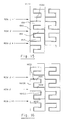
- Fig. 5 is a block diagram, partially in schematic form, of a portion of another prior art apparatus.
- Fig. 6 shows a plan view of an electrode pattern and reference conductors in accordance with an embodiment of the invention.
- Fig. 7 shows a variation of the Fig. 6 embodiment, with a different arrangement of reference conductors.
- Fig. 8 shows a cross-sectional view of the devices of an array in accordance with a further embodiment of the invention.
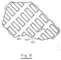
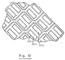
- Fig.s 9 and 10 show plan views of two arrangements of electrodes and reference conductive regions of the Fig. 8 embodiment.
- Fig. 11 shows a cross-sectional view of the devices of an array in accordance with a still further embodiment of the invention.
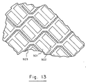
- Fig.s 12 and 13 show plan views of two arrangements of the reference conductive regions of the Fig. 11 embodiment.
- Fig.s 14, 14A, 15 and 16 show electrode configurations in accordance with further embodiments of the present invention.
- Referring to Fig. 1, there is shown a simplified schematic diagram of the type of
apparatus 10 in which the improvements of the invention are made. Asemiconductor substrate 11 has an array of devices formed in asurface 12 thereof, these devices serving as semiconductor controlled storage units. A layer of deformable material 13 (which may be, for example, an elastomer such as silicone gel) covers thesurface 12, and areflective layer 14 of conductive material is disposed over thedeformable layer 13. The semiconductor device array, and associatedcircuitry 80, to be described further hereinbelow, receives and samples a video signal, the samples ultimately being stored as a charge pattern on thesurface 12 ofsemiconductor 11. The electric field associated with the charge pattern results in a force with respect to thelayer 14 which deforms thedeformable material 13 andlayer 14 so that information is contained in thereflective layer 14 in the form of depressions or ripples which are similar to a phase diffraction grating. This information is then displayed on ascreen 15, such as by using a Schlieren type of optical system. - The optical system depicted in Fig. 1 can be generally of the type disclosed in U.S. Patent No.s 3,084,590, 3,882,271, and 4,641,193. In this
system arc electrodes 20 generate an intense light source that is directed by a curved mirror 21 over a masking system which includes a plurality of reflectingbars 23 separated by transparent areas or slits 24. Themasking system 22 is positioned so that the light reflected from thebars 23 is transmitted toward alens 25 where it is focused into parallel rays. These rays are incident on the deformedreflective surface 14 and are reflected back through thelens 25 toward the masking system. If, at a given instant, there were no depressions on thesurface 14 to divert the light rays, the rays effectively emanating from eachbar 23 would be focused bylens 25 on a bar and no light would be incident on thescreen 15. However, if there are depressions in thesurface 14 they will act as diffraction gratings and some light will be diffracted and ultimately pass through theslits 24. The portion of a light rays transmitted through a particular slit depends on the amplitude of the infinitesimal diffraction grating from which the ray was diffracted. Thus, an appropriate pattern of diffraction gratings, resulting from a selected charge pattern, will yield a desired image on thescreen 15. The charge pattern is stored by the array of semiconductor devices, to be described, in thesemiconductor substrate 11. In embodiments hereof, the array of semiconductor devices is arranged in a diagonal pattern, and the Schlieren bars are also oriented diagonally, as shown in Fig. 1. - Reference to prior art light modulator systems can be made to the abovereferenced U.S. Patent No. 3,882,271, and also to the U.S. Patent No. 4,441,791, which is of a different type in that it discloses a deformable mirror mounted on a grid over an array of semiconductor devices to form air-gap capacitors. Deformations of the mirror surface can be converted into an image by an optical system.
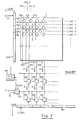
- Referring to Fig. 2, there is shown an array of devices in
semiconductor substrate 11. In the diagram of Fig. 2, each device orelement 100 is illustrated by itsdeflection region 300, which is shown as being a square in the prior system, the squares being oriented and arranged in a diagonal pattern; i.e., with the deflection electrodes of each row of the array being offset horizontally with respect to its adjacent rows. - In the Fig. 2 system, the lines of
elements 100 are numbered at the right of the Figure asline 1,line 2, etc., and illustrative elements from a central exemplary portion of the array are shown in Fig. 3 which shows a small portion of four consecutive lines designated using the generalized terminology of line j,line j+ 1,line j+ 2, andline j+ 3. In Fig. 2, the columns of the array are numbered ascolumn 1,column 2,column 3, etc., and in Fig. 3 the columns from a central exemplary portion of the array, are designated as column k, column k+1, column k+2, and column k+3. Each element of a column of the array is coupled in co:mmon, in a manner to be described, to acommon column conductor 150 for that line, as seen in Fig.s 2 and 3. As seen in Fig. 2, the respective column conductors are coupled to respective sides of capacitors Co, the other sides of which are coupled to ground reference potential. [These and other groups of capacitors can be considered as storage registers, and it is noted that suitable analog registers (or digital registers in conjunction with conversion circuitry), such as charge coupled device registers, could alternatively be employed.] The column conductors and respective capacitors Co are also coupled, viarespective switches 160, to respective sides of capacitors C1, the other sides of which are also coupled to ground reference potential. [Again, these capacitors can be considered as a storage register.] Theswitches 160 are simultaneously enabled by a signal derived from the horizontal sync signal, H. The capacitors C1 are also each coupled, viarespective switches 165, to the output of anotherswitch 170. Theswitches 165 are respectively enabled by signals on the output lines of respective stages of ashift register 180. Theregister 180 is loaded at one end (the right end in Fig. 2) with a logical "1" (high) level which is clocked through the register at a basic system element rate, from a clock, not shown. In the referenced U.S. patents,switch 170 is operative, under control of the output offlip flop 185, and the clock signal, to couple either the video input signal or ground reference potential to the inputs ofswitches 165. The vertical synchronizing signal, V, is utilized to set a different initial state of theflip flop 185 for the beginning of each scanline of a given field. In this manner, theswitch 170 is used to load a scanline of information into capacitors C1 (via switches 165), under control ofregister 180, with successive samples of input video information alternating with ground reference potential. - The
row conductors 330 are coupled to respective outputs ofshift register 220, the outputs ofregister 220 being used to selectively enable the row conductors in sequence. Theregister 220 is clocked by the horizontal synchronizing signal, and is synchronized by the vertical synchronizing signal, V. At the beginning of each field, a signal derived from V is used to load the first stage of theshift register 220 with a logical "1" (high) level. At each horizontal scanline of the field, the logical "1" level is shifted to the next position in the register so that the row conductors are sequentially enabled, one line at a time. - In operation of the system of Fig.s 2 and 3, and as described in the referenced patents, a scanline of sampled video information is read sequentially into the capacitors C1 in alternation with ground reference potential. At the end of the scanline, a signal derived from the horizontal sync signal H is used to enable
switches 160, so that the sampled video information (and gnd, as the case may be) in the capacitors C1 is coupled to respective capacitors Co and therespective column conductors 150. This substantially stores the sampled elemental signals in capacitors Co where they are applied, during the next scanline (and while the next line of video information is being read into the respective capacitors C1), to the respective column conductors. The signal derived from H is also operative, at this time, to shift theregister 220 so as to enable the next row conductor for the duration of the next line. The capacitors C1 and Co are charged (or discharged, as the case may be) through low impedances, so they can be charged in the relatively short durations during which their respective switches are enabled. - Each elemental signal can now be transferred into the
respective deflection electrodes 300, of the two successive lines whose common row conductor has been enabled by the output of theregister 220. Every other signal level entered in capacitors Co was at ground reference potential. Therefore, the video signal samples for the given scanline will be transferred into the respective deflection electrodes of one of the lines associated with the enabled row conductor, and ground reference potential will be transferred into each of the deflection electrodes of the other line which shares the energized row conductor. - During the transfer from the input capacitors Co to the respective deflection electrodes of the lines associated with the enabled row conductor, which occurs during approximately one scanline period, the next scanline of video information is being read into the capacitors C1 (again, in alternation with ground reference potential). In this manner, substantially a full scanline duration is available for transfer of the signal from the capacitors Co into the capacitance associated with the respective deflection electrodes. In particular, this capacitance comprises the capacitor formed by each
deflection electrode 300 and the common electrode 14 (e.g. Fig.s 1 and 3) disposed above the deformable material (which is shown at ground reference potential in this example, but which can be operated at a negative bias voltage, as described in the referenced patents), and stray capacitance. In copending U.S. Patent Application Serial No. 053,572, assigned to the same assignee as the present application, there is disclosed a technique wherein the impedance in each column conductor between the input capacitor and its associated deflection electrodes is caused to vary in accordance with the change in video signal level from frame to frame, so as to achieve video noise reduction. -
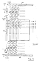
Fig.s devices 100 formed in the semiconductor substrate. The substrate is n-type silicon, and theregions regions 310 are coupled to associatedcolumn conductors 150. Theregions 320 are coupled to therespective deflection electrodes 300. Aninsulating region 325, typically a silicon dioxide layer, covers the semiconductor region betweendiffusions respective row conductors 330 are disposed aboveoxide layers 325, of the devices of their associated rows and serve as gates which, when energized or enabled, cause p-channel conduction between theregions deflection electrodes 300 of the devices on the enabled rows. Thedeflection electrodes 300 have top flat regions which extend over their associated devices and are spaced therefrom by insulating material such assilicon dioxide 329. The row switching, at the line rate of operation, permits use of polysilicon, while the faster column switching employs metal conductors in the present embodiments. - In the system of Fig.s 2-4, as set forth in the referenced patents, the system clock rate used to clock the sampled video signal into the storage capacitors (and ultimately into the array) is twice the rate at which video information is being entered, since half the time is being used to clock ground reference potential into every other horizontal element of a line. As described in the referenced patents, by using the system illustrated in Fig. 5, a clock rate can be used which is the same as the rate at which information is entered into the array. The device display electrodes of Fig. 5 are shown as being in the same general configuration as in Fig. 2. The
row conductors 530 are coupled to the outputs of ashift register 520, and operate like their counterparts in Fig. 2 to sequentially enable row pairs of devices. Thecolumn conductors 551 of the odd columns are coupled to circuitry similar to that of Fig. 2; namely, to respective capacitors C2a,respective switches 560 that are again enabled by a signal derived from the horizontal sync signal H, respective capacitors C2b, andrespective switches 565 which are enabled by respective outputs ofshift register 580, which is clocked at the basic system clock rate and operates to successively enable theswitches 565. The input toswitches 565 is the output of aswitch 585 which passes the input video signal during odd video fields and passes ground reference potential during even video fields. - The
even column conductors 552 are coupled to similar circuitry which includes respective capacitors C3a,respective switches 570 that are enabled by a signal derived from the horizontal sync signal H, respective capacitors C3b, andrespective switches 575 which, again, are sequentially enabled by respective output stages of a shift register (590) which is clocked at the basic system clock rate and operates to successively enable theswitches 575. The input toswitches 575 is the output of aswitch 595 that is operative to pass the input video signal during even video fields and ground reference potential during odd video fields of a video frame. In the system of Fig. 5, the clock rate used can be half of that which was employed in the Fig. 2 embodiment, since the odd and even subsystems are utilized simultaneously to read in and transfer sampled input video signals and ground reference potential (as the case may be) into respective odd and even rows of the array devices. - In operation of the system of Fig. 5, during an odd video field the
switch 585 is operative to pass the input video signal so that, for example, during the first video scanline the input video signal is sampled, under control ofshift register 580, and stored in capacitors C2a. Simultaneously,switch 595 is passing ground reference potential, which is being read into capacitors C3a under control ofshift register 590. At the end of the first scanline, theswitches first row conductor 530, which is coupled to the devices oflines lines switches 585 and 595) and ground reference potential is transferred intoline 1 while the sampled video signal is transferred intoline 2. It is noted in the referenced patents that a separate switching arrangement, such as for directly switching ground reference potential to the appropriate activated row, could be used. - Embodiments of the invention will now be described. In the embodiment of Fig. 6, each of the electrodes 300 (e.g. are coupled to
diffusion region 320 in Fig. 4) comprises a pair of relatively large areaconductive regions conductive region 300C. Theregions common metalization 600 that can be coupled to a suitable referenced potential, Vref. The reference conductors are separated from the electrodes, thesilicon dioxide 329 below (see also Fig. 4) being visible between the separations in Fig. 6. - In operation, the signal on each electrode (as compared to the reference potential on the common metalization 600) will cause forces on the conductive/reflective layer 14 (e.g. Fig. 4), and will result in image formation with twice as many grating lines for the same number of electrodes, due to the presence of the spaced electrode fingers. It will be understood that in the addressing of the individual electrodes, since a reference potential (Vref in Fig. 6) is applied to the reference conductors, it is not necessary to insert ground reference potential into every other line, and each row of electrodes will be individually addressed.
- In the embodiment of Fig. 6, if the signals applied to the reference conductors are the same and the signals applied to the electrodes are of the same polarity over a period of time, the light modulator can suffer from a permanent "memory"; that is, a permanent or semi-permanent pattern of protrusions and/or depressions in the conductive/reflective layer (and the elastomer layer below) which result from deflection of particular regions of the conductive/
reflective layer 14 always being in the same direction. This can result in artifacts in the ultimately presented image. - One way of alleviating the "memory" problem is to vary the polarity of the signals applied to the electrodes of the array. For example, in the embodiment of Fig. 6, during one frame the input video signal can be applied with a black-to-white polarity in one direction (for example, with 0 volts as black and 20 volts as white), and during the next video frame, the input video signal can be applied with black-to-white polarity in the opposite direction (for example, with black at 0 volts and white at -20 volts).
- The application of a different polarity of input signals to the electrodes during successive frames is useful in alleviating the problem of undesired "memory" of the modulator structure. However, the need to have voltage variations over a wider range (as in the example above) may be problematic.
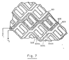
- Fig. 7 illustrates another embodiment of the invention which provides a solution to the stated problem. In this embodiment, the
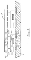
electrodes 300 are of the same configuration as in the Fig. 6 embodiment. However, in this case, the common metalization which comprises the reference conductors is divided so that individual scanlines of elements can have reference conductors at different reference potentials, for example V₁ for one line and V₂ for the next line, as shown in Fig. 7. [Three separatedreference conductors reflective layer 14 is a negative bias potential -Vb (see, for example, U.S. Patent No. 4,639,788), during one frame the reference potential applied to the reference conductors could be 0 volts, with the applied video signal varying between 0 volts (for black) and 20 volts (for white); whereas, during the next frame the reference potential could be 20 volts, with the applied video signal varying between 20 volts (for black) and 0 volts (for white). In this arrangement, since the picture information for each line is retained for a full field, the reference potentials should be switched, a line at a time, as each new line of video information is read into the array. This is achieved in the embodiments of Fig.s 7, 10 and 13 hereof by separately connecting the reference conductors associated with each line of the array. A suitable flip-flop and switch (as first illustrated above) can be used to select the reference potentials, which can then be read in, a line at a time in conjunction with the video, using a register, in the manner first shown hereinabove. The means for selection of desired black and white levels, and the polarity of the video signals, is well known in the art. - Referring to Fig. 8, there is shown a further embodiment of the invention, wherein each of the
electrodes 300 has conductive regions at two different levels. The elements in Fig. 8 which are of like reference numerals to elements of Fig. 4 serve the same or similar function. In Fig. 8, however, each of theelectrodes 300 has asurface region 300G at a first level above the semiconductor substrate (and above its respective semiconductor device, in the illustrated configuration), and a pair of further spaced apartsurface regions vertical extensions layer 829 of silicon dioxide. Theconductive region 300G, at the first level, is preferably of substantial area, so as to help prevent spurious light from reaching the semiconductor surface. If desired, reference conductive regions can also be provided at the first level. Referenceconductive regions 800 are provided at the second level. The pattern of electrodes and reference conductive regions can be as shown in Fig.s 9 and 10; i.e., similar to Fig.s 6 and 7, respectively, but with no need for connection between the electrode fingers at the second level (since they are connected from below). - Operation of the embodiments illustrated in Fig.s 8-10 is similar to the operation described with reference to Fig.s 6 and 7, except that the electrodes and reference conductive regions are at the second level. They exert their forces on the conductive/
reflective layer 14, as previously described, by virtue of the signals applied thereto. Although a further level of metallization is needed (as compared to the embodiments of Fig.s 6 and 7), there is improved light immunity, and the exposed connections between electrode fingers (e.g. 300C in Fig.s 6 or 7) are eliminated. - In the embodiments of Fig.s 11-13 the electrodes are at a first level and the second level contains only reference conductive regions. As shown in Fig. 11, for example, the
electrodes 300 can be in a configuration similar to that illustrated in conjunction with Fig. 4. In this case, however,reference conductors 910 are seen to be provided at the second level, which is again separated from the first level by an insulating layer (929). Thereference conductors 910 are seen to overlay only a portion of an electrode orelectrodes 300. A reference potential (in Fig. 12, or reference potentials, in Fig. 13) are applied to the . reference conductive regions. Due to the presence of the reference conductive regions, the plurality of portions of each electrode (there being division into two portions in this case, although division into more portions can be employed, if desired) results in the exposed portions of each electrode (i.e., those portions which are not covered by a reference conductive region) exerting a separate force with respect to the reflective/conductive layer 14. This results in a doubling (in this case) of the number of grating lines obtained from the array. In the embodiment of Fig. 12, the reference conductive electrodes are all coupled together in a common metallization, and a pair of spaced apertures, which are rectangular in this illustration, are positioned over two regions of each electrode. In Fig. 12, two of the apertures are also designated byreference numerals electrode 300 below. - In the embodiment of Fig. 13, the reference conductive regions associated with each scan line are separate (as in the prior embodiments of Fig.s 7 and 10), so that different reference potentials can be applied to different lines.
- Fig.s 14-16 illustrate electrode configurations in accordance with a further embodiment of the present invention. In the embodiment of Fig. 14, which is preferred for displaying diagonally sampled signals, each
conductive electrode 1400 has a centralvertical portion 1410, and three generally rectangularhorizontal fingers element 1400 is considered to be on line (or row) j, at which itscentral finger 1412 is located, then itsuppermost finger 1411 is seen to be interleaved with the two lower fingers of the adjacent electrodes in the row above, i.e., row j-1. Also, itslowermost finger 1413 is interleaved with the two upper fingers of the adjacent electrodes in the row below. The electrodes of the array are spaced slightly apart, and the insulator below (e.g. silicon dioxide 329 of Fig. 4) is visible between the electrodes. In operation, and as disclosed in U.S. Patent No.s 4,639,788 and 4,641,193, a reference potential can be applied to, say, odd numbered lines and input video applied to even numbered lines during one field, and then during the next field a reference potential can be applied to even numbered lines and input video applied to odd numbered lines. This avoids undesired "memory" in the modulator structure, as previously discussed. However, with previous electrode configurations this resulted in halving the grating wave length per pixel. The disclosed configuration, wherein fingers of an active electrode extend into the regions of the lines above and below, provides substantial improvement in this regard. The number of fingers can be increased, if desired, and the shape of the configuration can be modified, e.g. to minimize the width of the central vertical portion, (which does not contribute to the grating), as shown, for example, in Fig. 14A wherein the illustrated electrode has five fingers, two of which will be interleaved with fingers of electrodes in the row above, and two of which will be interleaved with fingers of the row below. - Fig.s 15 and 16 show examples of electrode configurations which can be utilized in conjunction with cardinal sampling systems, and which have the same type of advantage as that just described. In Fig. 15, an
electrode 1500 has amiddle finger 1512 on a row j with itsuppermost finger 1511 interleaved with fingers of the electrode of the row above (row j-1) and itslowermost finger 1513 interleaved with fingers of the electrode of the row below (row j+1). The fingers of row j (and other rows of the same odd/even sense) extend to the right of avertical portion 1510, whereas the fingers of rows of the opposite sense (e.g. j-1, j+1, etc.) extend to the left of their vertical portion. The embodiment shown in Fig. 16 is similar, but the fingers ofelectrode 1600 form an S-shaped configuration, with two vertical portions. Thevertical portion 1610A connects thecentral finger 1612 with theuppermost finger 1611, and thevertical portion 1610B connects thecentral finger 1612 with the lowermost finger 1613. - The arrays of semiconductor devices hereof can be fabricated, for example, utilizing known semiconductor lithographic processes. Appropriate masks for the patterns of diffusions, electrodes, contracts, polysilicon and conductive layers, etc., are designed and utilized in sequences of selective diffusions, layer deposition, selective etching, electrode deposition, etc. (in the requisite order, as known in the art). The
deformable layer 13 and conductive and reflective layer or layers 14 can be applied using techniques set forth, for example, in U.S. Patent No.s. 4,529,620 and 4,626,920, assigned to the same assignee as the present application. - The invention has been described with reference to particular preferred embodiments, but variations in for example, the number, orientation, and shape of the electrode fingers are possible.
Claims (24)
each electrode of said array having a plurality of spaced conductive regions having respective surfaces of relatively large area in a common plane, the plurality of conductive regions of each said electrode being electrically connected in common by at least one conductor having, at most, a relatively small area in said plane;
reference conductive regions having surfaces in said plane between the surfaces of said electrodes and separated therefrom, at least some of said reference conductive regions being electrically connected in common; and
means for applying said input video signals to said electrodes of said array, and for applying at least one reference potential to said reference conductive regions.
a semiconductor substrate having an array of columns and rows of devices formed on a surface thereof, said devices comprising: a transistor formed in said substrate; a conductive electrode coupled to said transistor, said electrode having a first surface region at a first level above said semiconductor substrate and a plurality of further spaced apart surface regions at a second level above said first level;
reference conductive regions having surfaces at said second level between the further surface regions of said electrodes and separated therefrom, at least some of said reference conductive regions being electrically connected in common;
means for selectively applying said video signals to said transistors of said array and for controlling said transistors so as to selectively couple said video signals to said electrodes;
means, for applying at least one reference potential to said reference conductive regions;
a conductive/reflective layer spaced from said second level;
a layer of deformable material between said second level and said conductive/reflective layer; and
means for converting deformations of said conductive/reflective layer into an image.
a semiconductor substrate having an array of columns and rows of devices formed on a surface thereof, said devices comprising: a transistor formed in said substrate; a conductive electrode coupled to said transistor and having a surface region at a first level above said semiconductor substrate; and a plurality of reference conductive regions at a second level above said surface region;
means for selectively applying said video signals to said transistors of said array and for controlling said transistors so as to selectively couple said video signals to said conductive electrodes;
means for applying at least one reference potential to said reference conductive regions;
a conductive/reflective layer spaced from said second level;
a layer of deformable material between said second level and said conductive/reflective layer; and
means for converting deformations of said conductive/reflective layer into an image.
the electrodes of said array having at least three electrically connected fingers such that at least one of said fingers is interleaved with fingers of an electrode in a row above in said array and at least another of said fingers is interleaved with fingers of an electrode of a row below in said array; and
means for applying video signals to said devices.
Applications Claiming Priority (4)
| Application Number | Priority Date | Filing Date | Title |
|---|---|---|---|
| US232923 | 1981-02-09 | ||
| US07/094,382 US4878122A (en) | 1987-09-04 | 1987-09-04 | Light modulator video display apparatus |
| US94382 | 1987-09-04 | ||
| US07/232,923 US4879602A (en) | 1987-09-04 | 1988-08-18 | Electrode patterns for solid state light modulator |
Publications (3)
| Publication Number | Publication Date |
|---|---|
| EP0306308A2 true EP0306308A2 (en) | 1989-03-08 |
| EP0306308A3 EP0306308A3 (en) | 1989-12-13 |
| EP0306308B1 EP0306308B1 (en) | 1994-04-20 |
Family
ID=26788796
Family Applications (1)
| Application Number | Title | Priority Date | Filing Date |
|---|---|---|---|
| EP88308098A Expired - Lifetime EP0306308B1 (en) | 1987-09-04 | 1988-09-01 | Video display apparatus |
Country Status (5)
| Country | Link |
|---|---|
| US (1) | US4879602A (en) |
| EP (1) | EP0306308B1 (en) |
| JP (1) | JPH01135187A (en) |
| CA (1) | CA1315027C (en) |
| DE (1) | DE3889171T2 (en) |
Cited By (38)
| Publication number | Priority date | Publication date | Assignee | Title |
|---|---|---|---|---|
| WO1996041217A1 (en) * | 1995-06-07 | 1996-12-19 | Silicon Light Machines | Flat diffraction grating light valve |
| GB2319133A (en) * | 1996-11-07 | 1998-05-13 | Umax Data Systems Inc | Colour scanner using nonsquare CCD elements |
| US6714337B1 (en) | 2002-06-28 | 2004-03-30 | Silicon Light Machines | Method and device for modulating a light beam and having an improved gamma response |
| US6712480B1 (en) | 2002-09-27 | 2004-03-30 | Silicon Light Machines | Controlled curvature of stressed micro-structures |
| US6767751B2 (en) | 2002-05-28 | 2004-07-27 | Silicon Light Machines, Inc. | Integrated driver process flow |
| US6782205B2 (en) | 2001-06-25 | 2004-08-24 | Silicon Light Machines | Method and apparatus for dynamic equalization in wavelength division multiplexing |
| US6785001B2 (en) | 2001-08-21 | 2004-08-31 | Silicon Light Machines, Inc. | Method and apparatus for measuring wavelength jitter of light signal |
| US6800238B1 (en) | 2002-01-15 | 2004-10-05 | Silicon Light Machines, Inc. | Method for domain patterning in low coercive field ferroelectrics |
| US6801354B1 (en) | 2002-08-20 | 2004-10-05 | Silicon Light Machines, Inc. | 2-D diffraction grating for substantially eliminating polarization dependent losses |
| US6806997B1 (en) | 2003-02-28 | 2004-10-19 | Silicon Light Machines, Inc. | Patterned diffractive light modulator ribbon for PDL reduction |
| US6813059B2 (en) | 2002-06-28 | 2004-11-02 | Silicon Light Machines, Inc. | Reduced formation of asperities in contact micro-structures |
| US6822797B1 (en) | 2002-05-31 | 2004-11-23 | Silicon Light Machines, Inc. | Light modulator structure for producing high-contrast operation using zero-order light |
| US6829077B1 (en) | 2003-02-28 | 2004-12-07 | Silicon Light Machines, Inc. | Diffractive light modulator with dynamically rotatable diffraction plane |
| US6829092B2 (en) | 2001-08-15 | 2004-12-07 | Silicon Light Machines, Inc. | Blazed grating light valve |
| US6839479B2 (en) | 2002-05-29 | 2005-01-04 | Silicon Light Machines Corporation | Optical switch |
| US7046420B1 (en) | 2003-02-28 | 2006-05-16 | Silicon Light Machines Corporation | MEM micro-structures and methods of making the same |
| US7667884B2 (en) | 2004-09-27 | 2010-02-23 | Qualcomm Mems Technologies, Inc. | Interferometric modulators having charge persistence |
| US7675669B2 (en) | 2004-09-27 | 2010-03-09 | Qualcomm Mems Technologies, Inc. | Method and system for driving interferometric modulators |
| US7679627B2 (en) | 2004-09-27 | 2010-03-16 | Qualcomm Mems Technologies, Inc. | Controller and driver features for bi-stable display |
| US7702192B2 (en) | 2006-06-21 | 2010-04-20 | Qualcomm Mems Technologies, Inc. | Systems and methods for driving MEMS display |
| US7724993B2 (en) | 2004-09-27 | 2010-05-25 | Qualcomm Mems Technologies, Inc. | MEMS switches with deforming membranes |
| US7777715B2 (en) | 2006-06-29 | 2010-08-17 | Qualcomm Mems Technologies, Inc. | Passive circuits for de-multiplexing display inputs |
| US7843410B2 (en) | 2004-09-27 | 2010-11-30 | Qualcomm Mems Technologies, Inc. | Method and device for electrically programmable display |
| US7889163B2 (en) | 2004-08-27 | 2011-02-15 | Qualcomm Mems Technologies, Inc. | Drive method for MEMS devices |
| US7920136B2 (en) | 2005-05-05 | 2011-04-05 | Qualcomm Mems Technologies, Inc. | System and method of driving a MEMS display device |
| US7948457B2 (en) | 2005-05-05 | 2011-05-24 | Qualcomm Mems Technologies, Inc. | Systems and methods of actuating MEMS display elements |
| US8049713B2 (en) | 2006-04-24 | 2011-11-01 | Qualcomm Mems Technologies, Inc. | Power consumption optimized display update |
| US8174469B2 (en) | 2005-05-05 | 2012-05-08 | Qualcomm Mems Technologies, Inc. | Dynamic driver IC and display panel configuration |
| US8194056B2 (en) | 2006-02-09 | 2012-06-05 | Qualcomm Mems Technologies Inc. | Method and system for writing data to MEMS display elements |
| US8310441B2 (en) | 2004-09-27 | 2012-11-13 | Qualcomm Mems Technologies, Inc. | Method and system for writing data to MEMS display elements |
| US8391630B2 (en) | 2005-12-22 | 2013-03-05 | Qualcomm Mems Technologies, Inc. | System and method for power reduction when decompressing video streams for interferometric modulator displays |
| US8736590B2 (en) | 2009-03-27 | 2014-05-27 | Qualcomm Mems Technologies, Inc. | Low voltage driver scheme for interferometric modulators |
| US8878771B2 (en) | 2004-09-27 | 2014-11-04 | Qualcomm Mems Technologies, Inc. | Method and system for reducing power consumption in a display |
| US8878825B2 (en) | 2004-09-27 | 2014-11-04 | Qualcomm Mems Technologies, Inc. | System and method for providing a variable refresh rate of an interferometric modulator display |
| US8928967B2 (en) | 1998-04-08 | 2015-01-06 | Qualcomm Mems Technologies, Inc. | Method and device for modulating light |
| US8971675B2 (en) | 2006-01-13 | 2015-03-03 | Qualcomm Mems Technologies, Inc. | Interconnect structure for MEMS device |
| US9110289B2 (en) | 1998-04-08 | 2015-08-18 | Qualcomm Mems Technologies, Inc. | Device for modulating light with multiple electrodes |
| US9641826B1 (en) | 2011-10-06 | 2017-05-02 | Evans & Sutherland Computer Corporation | System and method for displaying distant 3-D stereo on a dome surface |
Families Citing this family (27)
| Publication number | Priority date | Publication date | Assignee | Title |
|---|---|---|---|---|
| US4803880A (en) * | 1987-12-21 | 1989-02-14 | United Technologies Corporation | Hollow article forging process |
| US5124834A (en) * | 1989-11-16 | 1992-06-23 | General Electric Company | Transferrable, self-supporting pellicle for elastomer light valve displays and method for making the same |
| US5233459A (en) * | 1991-03-06 | 1993-08-03 | Massachusetts Institute Of Technology | Electric display device |
| US5223971A (en) * | 1991-12-31 | 1993-06-29 | Texas Instruments Incorporated | Light beam steering with deformable membrane device |
| US5521746A (en) * | 1993-02-22 | 1996-05-28 | Engle; Craig D. | Poppet valve modulator |
| US5521747A (en) * | 1993-02-22 | 1996-05-28 | Engle; Craig D. | Electronically addressed deformable media light modulator |
| US5489952A (en) * | 1993-07-14 | 1996-02-06 | Texas Instruments Incorporated | Method and device for multi-format television |
| US5448395A (en) * | 1993-08-03 | 1995-09-05 | Northrop Grumman Corporation | Non-mechanical step scanner for electro-optical sensors |
| US5386250A (en) * | 1993-08-09 | 1995-01-31 | Philips Electronics North America Corp. | Two-source illumination system |
| US5640214A (en) * | 1994-09-30 | 1997-06-17 | Texas Instruments Incorporated | Printer and display systems with bidirectional light collection structures |
| US5623361A (en) * | 1995-01-09 | 1997-04-22 | Engle; Craig D. | Enhanced wavefront phase modulator device |
| US5612753A (en) * | 1995-01-27 | 1997-03-18 | Texas Instruments Incorporated | Full-color projection display system using two light modulators |
| US5530482A (en) * | 1995-03-21 | 1996-06-25 | Texas Instruments Incorporated | Pixel data processing for spatial light modulator having staggered pixels |
| US6969635B2 (en) | 2000-12-07 | 2005-11-29 | Reflectivity, Inc. | Methods for depositing, releasing and packaging micro-electromechanical devices on wafer substrates |
| US5681103A (en) * | 1995-12-04 | 1997-10-28 | Ford Global Technologies, Inc. | Electrostatic shutter particularly for an automotive headlamp |
| US5829870A (en) * | 1995-12-04 | 1998-11-03 | Ford Global Technologies, Inc. | Variable headlamp system for an automotive vehicle using an electrostatic shutter |
| US5867301A (en) * | 1996-04-22 | 1999-02-02 | Engle; Craig D. | Phase modulating device |
| US7196740B2 (en) | 2000-08-30 | 2007-03-27 | Texas Instruments Incorporated | Projection TV with improved micromirror array |
| US7023606B2 (en) | 2001-08-03 | 2006-04-04 | Reflectivity, Inc | Micromirror array for projection TV |
| WO2004023197A1 (en) * | 2002-09-06 | 2004-03-18 | Photonyx As | Method and device for variable optical attenuator |
| US7042622B2 (en) | 2003-10-30 | 2006-05-09 | Reflectivity, Inc | Micromirror and post arrangements on substrates |
| US6886944B2 (en) * | 2003-05-13 | 2005-05-03 | Hewlett-Packard Development Company, L.P. | Projector brightness enhancement using rectilinear apertures |
| WO2008073449A2 (en) | 2006-12-12 | 2008-06-19 | Evans & Sutherland Computer Corporation | System and method for aligning rgb light in a single modulator projector |
| US8358317B2 (en) | 2008-05-23 | 2013-01-22 | Evans & Sutherland Computer Corporation | System and method for displaying a planar image on a curved surface |
| US8702248B1 (en) | 2008-06-11 | 2014-04-22 | Evans & Sutherland Computer Corporation | Projection method for reducing interpixel gaps on a viewing surface |
| US8077378B1 (en) | 2008-11-12 | 2011-12-13 | Evans & Sutherland Computer Corporation | Calibration system and method for light modulation device |
| US10230928B2 (en) | 2014-10-27 | 2019-03-12 | Texas Instruments Incorporated | Color recapture using polarization recovery in a color-field sequential display system |
Citations (3)
| Publication number | Priority date | Publication date | Assignee | Title |
|---|---|---|---|---|
| GB987867A (en) * | 1960-06-30 | 1965-03-31 | Foerderung Forschung Gmbh | Apparatus for amplifying the brightness of an optically formed image |
| US4615595A (en) * | 1984-10-10 | 1986-10-07 | Texas Instruments Incorporated | Frame addressed spatial light modulator |
| US4639788A (en) * | 1984-12-07 | 1987-01-27 | New York Institute Of Technology | Video display method and apparatus |
Family Cites Families (10)
| Publication number | Priority date | Publication date | Assignee | Title |
|---|---|---|---|---|
| US3882271A (en) * | 1973-11-13 | 1975-05-06 | Columbia Broadcasting Syst Inc | Display using array of charge storage devices |
| JPS5941169B2 (en) * | 1975-12-25 | 1984-10-05 | シチズン時計株式会社 | Elastomer |
| US4229732A (en) * | 1978-12-11 | 1980-10-21 | International Business Machines Corporation | Micromechanical display logic and array |
| NL8001281A (en) * | 1980-03-04 | 1981-10-01 | Philips Nv | DISPLAY DEVICE. |
| US4441791A (en) * | 1980-09-02 | 1984-04-10 | Texas Instruments Incorporated | Deformable mirror light modulator |
| US4387402A (en) * | 1980-10-28 | 1983-06-07 | Texas Instruments Incorporated | Charge injection imaging device for faithful (dynamic) scene representation |
| JPS5831669A (en) * | 1981-08-20 | 1983-02-24 | Matsushita Electric Ind Co Ltd | Solid-state image pickup device |
| US4529620A (en) * | 1984-01-30 | 1985-07-16 | New York Institute Of Technology | Method of making deformable light modulator structure |
| US4626920A (en) * | 1984-01-30 | 1986-12-02 | New York Institute Of Technology | Solid state light modulator structure |
| US4641193A (en) * | 1984-12-07 | 1987-02-03 | New York Institute Of Technology | Video display apparatus and method |
-
1988
- 1988-08-18 US US07/232,923 patent/US4879602A/en not_active Expired - Lifetime
- 1988-09-01 EP EP88308098A patent/EP0306308B1/en not_active Expired - Lifetime
- 1988-09-01 DE DE3889171T patent/DE3889171T2/en not_active Expired - Fee Related
- 1988-09-02 CA CA000576489A patent/CA1315027C/en not_active Expired - Fee Related
- 1988-09-05 JP JP63220600A patent/JPH01135187A/en active Pending
Patent Citations (3)
| Publication number | Priority date | Publication date | Assignee | Title |
|---|---|---|---|---|
| GB987867A (en) * | 1960-06-30 | 1965-03-31 | Foerderung Forschung Gmbh | Apparatus for amplifying the brightness of an optically formed image |
| US4615595A (en) * | 1984-10-10 | 1986-10-07 | Texas Instruments Incorporated | Frame addressed spatial light modulator |
| US4639788A (en) * | 1984-12-07 | 1987-01-27 | New York Institute Of Technology | Video display method and apparatus |
Cited By (41)
| Publication number | Priority date | Publication date | Assignee | Title |
|---|---|---|---|---|
| WO1996041217A1 (en) * | 1995-06-07 | 1996-12-19 | Silicon Light Machines | Flat diffraction grating light valve |
| GB2319133A (en) * | 1996-11-07 | 1998-05-13 | Umax Data Systems Inc | Colour scanner using nonsquare CCD elements |
| US8928967B2 (en) | 1998-04-08 | 2015-01-06 | Qualcomm Mems Technologies, Inc. | Method and device for modulating light |
| US9110289B2 (en) | 1998-04-08 | 2015-08-18 | Qualcomm Mems Technologies, Inc. | Device for modulating light with multiple electrodes |
| US6782205B2 (en) | 2001-06-25 | 2004-08-24 | Silicon Light Machines | Method and apparatus for dynamic equalization in wavelength division multiplexing |
| US6829092B2 (en) | 2001-08-15 | 2004-12-07 | Silicon Light Machines, Inc. | Blazed grating light valve |
| US6785001B2 (en) | 2001-08-21 | 2004-08-31 | Silicon Light Machines, Inc. | Method and apparatus for measuring wavelength jitter of light signal |
| US6800238B1 (en) | 2002-01-15 | 2004-10-05 | Silicon Light Machines, Inc. | Method for domain patterning in low coercive field ferroelectrics |
| US6767751B2 (en) | 2002-05-28 | 2004-07-27 | Silicon Light Machines, Inc. | Integrated driver process flow |
| US6839479B2 (en) | 2002-05-29 | 2005-01-04 | Silicon Light Machines Corporation | Optical switch |
| US6822797B1 (en) | 2002-05-31 | 2004-11-23 | Silicon Light Machines, Inc. | Light modulator structure for producing high-contrast operation using zero-order light |
| US6813059B2 (en) | 2002-06-28 | 2004-11-02 | Silicon Light Machines, Inc. | Reduced formation of asperities in contact micro-structures |
| US6714337B1 (en) | 2002-06-28 | 2004-03-30 | Silicon Light Machines | Method and device for modulating a light beam and having an improved gamma response |
| US6801354B1 (en) | 2002-08-20 | 2004-10-05 | Silicon Light Machines, Inc. | 2-D diffraction grating for substantially eliminating polarization dependent losses |
| US6712480B1 (en) | 2002-09-27 | 2004-03-30 | Silicon Light Machines | Controlled curvature of stressed micro-structures |
| US6829077B1 (en) | 2003-02-28 | 2004-12-07 | Silicon Light Machines, Inc. | Diffractive light modulator with dynamically rotatable diffraction plane |
| US6806997B1 (en) | 2003-02-28 | 2004-10-19 | Silicon Light Machines, Inc. | Patterned diffractive light modulator ribbon for PDL reduction |
| US7046420B1 (en) | 2003-02-28 | 2006-05-16 | Silicon Light Machines Corporation | MEM micro-structures and methods of making the same |
| US7928940B2 (en) | 2004-08-27 | 2011-04-19 | Qualcomm Mems Technologies, Inc. | Drive method for MEMS devices |
| US7889163B2 (en) | 2004-08-27 | 2011-02-15 | Qualcomm Mems Technologies, Inc. | Drive method for MEMS devices |
| US7724993B2 (en) | 2004-09-27 | 2010-05-25 | Qualcomm Mems Technologies, Inc. | MEMS switches with deforming membranes |
| US8310441B2 (en) | 2004-09-27 | 2012-11-13 | Qualcomm Mems Technologies, Inc. | Method and system for writing data to MEMS display elements |
| US7843410B2 (en) | 2004-09-27 | 2010-11-30 | Qualcomm Mems Technologies, Inc. | Method and device for electrically programmable display |
| US7667884B2 (en) | 2004-09-27 | 2010-02-23 | Qualcomm Mems Technologies, Inc. | Interferometric modulators having charge persistence |
| US7675669B2 (en) | 2004-09-27 | 2010-03-09 | Qualcomm Mems Technologies, Inc. | Method and system for driving interferometric modulators |
| US7679627B2 (en) | 2004-09-27 | 2010-03-16 | Qualcomm Mems Technologies, Inc. | Controller and driver features for bi-stable display |
| US8878825B2 (en) | 2004-09-27 | 2014-11-04 | Qualcomm Mems Technologies, Inc. | System and method for providing a variable refresh rate of an interferometric modulator display |
| US8878771B2 (en) | 2004-09-27 | 2014-11-04 | Qualcomm Mems Technologies, Inc. | Method and system for reducing power consumption in a display |
| US8791897B2 (en) | 2004-09-27 | 2014-07-29 | Qualcomm Mems Technologies, Inc. | Method and system for writing data to MEMS display elements |
| US7948457B2 (en) | 2005-05-05 | 2011-05-24 | Qualcomm Mems Technologies, Inc. | Systems and methods of actuating MEMS display elements |
| US8174469B2 (en) | 2005-05-05 | 2012-05-08 | Qualcomm Mems Technologies, Inc. | Dynamic driver IC and display panel configuration |
| US7920136B2 (en) | 2005-05-05 | 2011-04-05 | Qualcomm Mems Technologies, Inc. | System and method of driving a MEMS display device |
| US8391630B2 (en) | 2005-12-22 | 2013-03-05 | Qualcomm Mems Technologies, Inc. | System and method for power reduction when decompressing video streams for interferometric modulator displays |
| US8971675B2 (en) | 2006-01-13 | 2015-03-03 | Qualcomm Mems Technologies, Inc. | Interconnect structure for MEMS device |
| US8194056B2 (en) | 2006-02-09 | 2012-06-05 | Qualcomm Mems Technologies Inc. | Method and system for writing data to MEMS display elements |
| US8049713B2 (en) | 2006-04-24 | 2011-11-01 | Qualcomm Mems Technologies, Inc. | Power consumption optimized display update |
| US7702192B2 (en) | 2006-06-21 | 2010-04-20 | Qualcomm Mems Technologies, Inc. | Systems and methods for driving MEMS display |
| US7777715B2 (en) | 2006-06-29 | 2010-08-17 | Qualcomm Mems Technologies, Inc. | Passive circuits for de-multiplexing display inputs |
| US8736590B2 (en) | 2009-03-27 | 2014-05-27 | Qualcomm Mems Technologies, Inc. | Low voltage driver scheme for interferometric modulators |
| US9641826B1 (en) | 2011-10-06 | 2017-05-02 | Evans & Sutherland Computer Corporation | System and method for displaying distant 3-D stereo on a dome surface |
| US10110876B1 (en) | 2011-10-06 | 2018-10-23 | Evans & Sutherland Computer Corporation | System and method for displaying images in 3-D stereo |
Also Published As
| Publication number | Publication date |
|---|---|
| DE3889171D1 (en) | 1994-05-26 |
| US4879602A (en) | 1989-11-07 |
| EP0306308B1 (en) | 1994-04-20 |
| DE3889171T2 (en) | 1994-09-01 |
| CA1315027C (en) | 1993-03-23 |
| EP0306308A3 (en) | 1989-12-13 |
| JPH01135187A (en) | 1989-05-26 |
Similar Documents
| Publication | Publication Date | Title |
|---|---|---|
| EP0306308B1 (en) | Video display apparatus | |
| US4641193A (en) | Video display apparatus and method | |
| KR890000649B1 (en) | Two-dimension adress apparatus | |
| JP4112974B2 (en) | Imager with adjustable resolution | |
| US4748507A (en) | Solid state imaging device having means to shift the image between scans and associated circuitry to improve the scanned image | |
| US4485380A (en) | Liquid crystal matrix display device | |
| EP0262665A2 (en) | CCD Area image sensor operable in both of line-sequential and interlace scannings and a method for operating the same | |
| US4212034A (en) | Solid-state image pickup device | |
| US3826926A (en) | Charge coupled device area imaging array | |
| KR100347507B1 (en) | CCD solid-state imaging device and its driving method | |
| US4878122A (en) | Light modulator video display apparatus | |
| US3882271A (en) | Display using array of charge storage devices | |
| JPH0320954B2 (en) | ||
| US4353084A (en) | Readout circuit for a monolithically integrated circuit for linear image scanning | |
| US4654713A (en) | Charge transfer photosensitive device | |
| US6583456B2 (en) | Image sensor with light receiving elements of differing areas and image reader both having semiconductor device | |
| US4032903A (en) | Charge injection device arrays | |
| JPS596111B2 (en) | area sensor | |
| US4851917A (en) | Solid state image pickup apparatus with interlaced row pair readout | |
| US4639788A (en) | Video display method and apparatus | |
| JP2931809B1 (en) | Imaging device | |
| US5760755A (en) | Electrostatic light valve system configurations | |
| US5304803A (en) | Infrared imaging array | |
| EP0184378B1 (en) | Video display apparatus and method | |
| EP0032504A1 (en) | Apparatus for storing and processing charge-packets. |
Legal Events
| Date | Code | Title | Description |
|---|---|---|---|
| PUAI | Public reference made under article 153(3) epc to a published international application that has entered the european phase |
Free format text: ORIGINAL CODE: 0009012 |
|
| AK | Designated contracting states |
Kind code of ref document: A2 Designated state(s): DE FR GB NL |
|
| PUAL | Search report despatched |
Free format text: ORIGINAL CODE: 0009013 |
|
| AK | Designated contracting states |
Kind code of ref document: A3 Designated state(s): DE FR GB NL |
|
| 17P | Request for examination filed |
Effective date: 19900530 |
|
| 17Q | First examination report despatched |
Effective date: 19920707 |
|
| GRAA | (expected) grant |
Free format text: ORIGINAL CODE: 0009210 |
|
| AK | Designated contracting states |
Kind code of ref document: B1 Designated state(s): DE FR GB NL |
|
| REF | Corresponds to: |
Ref document number: 3889171 Country of ref document: DE Date of ref document: 19940526 |
|
| ET | Fr: translation filed | ||
| PLBE | No opposition filed within time limit |
Free format text: ORIGINAL CODE: 0009261 |
|
| STAA | Information on the status of an ep patent application or granted ep patent |
Free format text: STATUS: NO OPPOSITION FILED WITHIN TIME LIMIT |
|
| 26N | No opposition filed | ||
| PGFP | Annual fee paid to national office [announced via postgrant information from national office to epo] |
Ref country code: NL Payment date: 19950922 Year of fee payment: 8 |
|
| PG25 | Lapsed in a contracting state [announced via postgrant information from national office to epo] |
Ref country code: NL Effective date: 19970401 |
|
| NLV4 | Nl: lapsed or anulled due to non-payment of the annual fee |
Effective date: 19970401 |
|
| PGFP | Annual fee paid to national office [announced via postgrant information from national office to epo] |
Ref country code: GB Payment date: 20000906 Year of fee payment: 13 |
|
| PGFP | Annual fee paid to national office [announced via postgrant information from national office to epo] |
Ref country code: DE Payment date: 20000911 Year of fee payment: 13 |
|
| PGFP | Annual fee paid to national office [announced via postgrant information from national office to epo] |
Ref country code: FR Payment date: 20000912 Year of fee payment: 13 |
|
| PG25 | Lapsed in a contracting state [announced via postgrant information from national office to epo] |
Ref country code: GB Free format text: LAPSE BECAUSE OF NON-PAYMENT OF DUE FEES Effective date: 20010901 |
|
| GBPC | Gb: european patent ceased through non-payment of renewal fee |
Effective date: 20010901 |
|
| PG25 | Lapsed in a contracting state [announced via postgrant information from national office to epo] |
Ref country code: DE Free format text: LAPSE BECAUSE OF NON-PAYMENT OF DUE FEES Effective date: 20020501 |
|
| PG25 | Lapsed in a contracting state [announced via postgrant information from national office to epo] |
Ref country code: FR Free format text: LAPSE BECAUSE OF NON-PAYMENT OF DUE FEES Effective date: 20020531 |
|
| REG | Reference to a national code |
Ref country code: FR Ref legal event code: ST |