EP0305741A2 - Semiconductor device with floating gate - Google Patents
Semiconductor device with floating gate Download PDFInfo
- Publication number
- EP0305741A2 EP0305741A2 EP88112312A EP88112312A EP0305741A2 EP 0305741 A2 EP0305741 A2 EP 0305741A2 EP 88112312 A EP88112312 A EP 88112312A EP 88112312 A EP88112312 A EP 88112312A EP 0305741 A2 EP0305741 A2 EP 0305741A2
- Authority
- EP
- European Patent Office
- Prior art keywords
- film
- insulating film
- layer
- semiconductor device
- transistor
- Prior art date
- Legal status (The legal status is an assumption and is not a legal conclusion. Google has not performed a legal analysis and makes no representation as to the accuracy of the status listed.)
- Granted
Links
- 239000004065 semiconductor Substances 0.000 title claims abstract description 44
- 238000007667 floating Methods 0.000 title claims abstract description 29
- VYPSYNLAJGMNEJ-UHFFFAOYSA-N Silicium dioxide Chemical compound O=[Si]=O VYPSYNLAJGMNEJ-UHFFFAOYSA-N 0.000 claims abstract description 49
- 229910052814 silicon oxide Inorganic materials 0.000 claims abstract description 49
- 229910052581 Si3N4 Inorganic materials 0.000 claims abstract description 14
- HQVNEWCFYHHQES-UHFFFAOYSA-N silicon nitride Chemical compound N12[Si]34N5[Si]62N3[Si]51N64 HQVNEWCFYHHQES-UHFFFAOYSA-N 0.000 claims abstract description 14
- XUIMIQQOPSSXEZ-UHFFFAOYSA-N Silicon Chemical compound [Si] XUIMIQQOPSSXEZ-UHFFFAOYSA-N 0.000 claims abstract description 13
- 229910052710 silicon Inorganic materials 0.000 claims abstract description 13
- 239000010703 silicon Substances 0.000 claims abstract description 13
- 239000000758 substrate Substances 0.000 claims abstract description 11
- 230000002093 peripheral effect Effects 0.000 claims description 32
- 239000000463 material Substances 0.000 claims 2
- 238000009413 insulation Methods 0.000 abstract description 2
- 239000010410 layer Substances 0.000 description 64
- 229910021420 polycrystalline silicon Inorganic materials 0.000 description 31
- 229910004205 SiNX Inorganic materials 0.000 description 23
- 238000000034 method Methods 0.000 description 15
- 230000015572 biosynthetic process Effects 0.000 description 9
- 238000005755 formation reaction Methods 0.000 description 9
- 238000007254 oxidation reaction Methods 0.000 description 9
- 239000012535 impurity Substances 0.000 description 8
- 238000004519 manufacturing process Methods 0.000 description 6
- 230000006866 deterioration Effects 0.000 description 4
- OAICVXFJPJFONN-UHFFFAOYSA-N Phosphorus Chemical compound [P] OAICVXFJPJFONN-UHFFFAOYSA-N 0.000 description 3
- XAGFODPZIPBFFR-UHFFFAOYSA-N aluminium Chemical compound [Al] XAGFODPZIPBFFR-UHFFFAOYSA-N 0.000 description 3
- 229910052782 aluminium Inorganic materials 0.000 description 3
- 230000015556 catabolic process Effects 0.000 description 3
- 238000009792 diffusion process Methods 0.000 description 3
- 239000007789 gas Substances 0.000 description 3
- 238000004518 low pressure chemical vapour deposition Methods 0.000 description 3
- 229910052698 phosphorus Inorganic materials 0.000 description 3
- 235000014786 phosphorus Nutrition 0.000 description 3
- 239000011574 phosphorus Substances 0.000 description 3
- 230000008878 coupling Effects 0.000 description 2
- 238000010168 coupling process Methods 0.000 description 2
- 238000005859 coupling reaction Methods 0.000 description 2
- 230000005684 electric field Effects 0.000 description 2
- 239000002784 hot electron Substances 0.000 description 2
- 238000002513 implantation Methods 0.000 description 2
- 238000002347 injection Methods 0.000 description 2
- 239000007924 injection Substances 0.000 description 2
- 238000005468 ion implantation Methods 0.000 description 2
- XHXFXVLFKHQFAL-UHFFFAOYSA-N phosphoryl trichloride Chemical compound ClP(Cl)(Cl)=O XHXFXVLFKHQFAL-UHFFFAOYSA-N 0.000 description 2
- 238000001020 plasma etching Methods 0.000 description 2
- 239000002356 single layer Substances 0.000 description 2
- UFHFLCQGNIYNRP-UHFFFAOYSA-N Hydrogen Chemical compound [H][H] UFHFLCQGNIYNRP-UHFFFAOYSA-N 0.000 description 1
- 229910019213 POCl3 Inorganic materials 0.000 description 1
- 229910003818 SiH2Cl2 Inorganic materials 0.000 description 1
- 238000007792 addition Methods 0.000 description 1
- 238000000137 annealing Methods 0.000 description 1
- 238000002485 combustion reaction Methods 0.000 description 1
- 238000005530 etching Methods 0.000 description 1
- 229910052739 hydrogen Inorganic materials 0.000 description 1
- 239000001257 hydrogen Substances 0.000 description 1
- 238000005286 illumination Methods 0.000 description 1
- 230000006872 improvement Effects 0.000 description 1
- 238000002955 isolation Methods 0.000 description 1
- 229920000136 polysorbate Polymers 0.000 description 1
- 230000005641 tunneling Effects 0.000 description 1
- 238000005406 washing Methods 0.000 description 1
Images

Classifications
-
- H—ELECTRICITY
- H01—ELECTRIC ELEMENTS
- H01L—SEMICONDUCTOR DEVICES NOT COVERED BY CLASS H10
- H01L27/00—Devices consisting of a plurality of semiconductor or other solid-state components formed in or on a common substrate
- H01L27/02—Devices consisting of a plurality of semiconductor or other solid-state components formed in or on a common substrate including semiconductor components specially adapted for rectifying, oscillating, amplifying or switching and having at least one potential-jump barrier or surface barrier; including integrated passive circuit elements with at least one potential-jump barrier or surface barrier
- H01L27/04—Devices consisting of a plurality of semiconductor or other solid-state components formed in or on a common substrate including semiconductor components specially adapted for rectifying, oscillating, amplifying or switching and having at least one potential-jump barrier or surface barrier; including integrated passive circuit elements with at least one potential-jump barrier or surface barrier the substrate being a semiconductor body
- H01L27/10—Devices consisting of a plurality of semiconductor or other solid-state components formed in or on a common substrate including semiconductor components specially adapted for rectifying, oscillating, amplifying or switching and having at least one potential-jump barrier or surface barrier; including integrated passive circuit elements with at least one potential-jump barrier or surface barrier the substrate being a semiconductor body including a plurality of individual components in a repetitive configuration
-
- H—ELECTRICITY
- H01—ELECTRIC ELEMENTS
- H01L—SEMICONDUCTOR DEVICES NOT COVERED BY CLASS H10
- H01L29/00—Semiconductor devices adapted for rectifying, amplifying, oscillating or switching, or capacitors or resistors with at least one potential-jump barrier or surface barrier, e.g. PN junction depletion layer or carrier concentration layer; Details of semiconductor bodies or of electrodes thereof ; Multistep manufacturing processes therefor
- H01L29/40—Electrodes ; Multistep manufacturing processes therefor
- H01L29/43—Electrodes ; Multistep manufacturing processes therefor characterised by the materials of which they are formed
- H01L29/49—Metal-insulator-semiconductor electrodes, e.g. gates of MOSFET
- H01L29/51—Insulating materials associated therewith
- H01L29/511—Insulating materials associated therewith with a compositional variation, e.g. multilayer structures
-
- H—ELECTRICITY
- H01—ELECTRIC ELEMENTS
- H01L—SEMICONDUCTOR DEVICES NOT COVERED BY CLASS H10
- H01L29/00—Semiconductor devices adapted for rectifying, amplifying, oscillating or switching, or capacitors or resistors with at least one potential-jump barrier or surface barrier, e.g. PN junction depletion layer or carrier concentration layer; Details of semiconductor bodies or of electrodes thereof ; Multistep manufacturing processes therefor
- H01L29/66—Types of semiconductor device ; Multistep manufacturing processes therefor
- H01L29/68—Types of semiconductor device ; Multistep manufacturing processes therefor controllable by only the electric current supplied, or only the electric potential applied, to an electrode which does not carry the current to be rectified, amplified or switched
- H01L29/76—Unipolar devices, e.g. field effect transistors
- H01L29/772—Field effect transistors
- H01L29/78—Field effect transistors with field effect produced by an insulated gate
- H01L29/788—Field effect transistors with field effect produced by an insulated gate with floating gate
- H01L29/7881—Programmable transistors with only two possible levels of programmation
- H01L29/7884—Programmable transistors with only two possible levels of programmation charging by hot carrier injection
- H01L29/7885—Hot carrier injection from the channel
-
- H—ELECTRICITY
- H10—SEMICONDUCTOR DEVICES; ELECTRIC SOLID-STATE DEVICES NOT OTHERWISE PROVIDED FOR
- H10B—ELECTRONIC MEMORY DEVICES
- H10B41/00—Electrically erasable-and-programmable ROM [EEPROM] devices comprising floating gates
- H10B41/40—Electrically erasable-and-programmable ROM [EEPROM] devices comprising floating gates characterised by the peripheral circuit region
- H10B41/42—Simultaneous manufacture of periphery and memory cells
- H10B41/43—Simultaneous manufacture of periphery and memory cells comprising only one type of peripheral transistor
- H10B41/46—Simultaneous manufacture of periphery and memory cells comprising only one type of peripheral transistor with an inter-gate dielectric layer also being used as part of the peripheral transistor
-
- H—ELECTRICITY
- H10—SEMICONDUCTOR DEVICES; ELECTRIC SOLID-STATE DEVICES NOT OTHERWISE PROVIDED FOR
- H10B—ELECTRONIC MEMORY DEVICES
- H10B41/00—Electrically erasable-and-programmable ROM [EEPROM] devices comprising floating gates
- H10B41/40—Electrically erasable-and-programmable ROM [EEPROM] devices comprising floating gates characterised by the peripheral circuit region
- H10B41/42—Simultaneous manufacture of periphery and memory cells
- H10B41/43—Simultaneous manufacture of periphery and memory cells comprising only one type of peripheral transistor
- H10B41/48—Simultaneous manufacture of periphery and memory cells comprising only one type of peripheral transistor with a tunnel dielectric layer also being used as part of the peripheral transistor
-
- H—ELECTRICITY
- H01—ELECTRIC ELEMENTS
- H01L—SEMICONDUCTOR DEVICES NOT COVERED BY CLASS H10
- H01L21/00—Processes or apparatus adapted for the manufacture or treatment of semiconductor or solid state devices or of parts thereof
- H01L21/02—Manufacture or treatment of semiconductor devices or of parts thereof
- H01L21/04—Manufacture or treatment of semiconductor devices or of parts thereof the devices having at least one potential-jump barrier or surface barrier, e.g. PN junction, depletion layer or carrier concentration layer
- H01L21/18—Manufacture or treatment of semiconductor devices or of parts thereof the devices having at least one potential-jump barrier or surface barrier, e.g. PN junction, depletion layer or carrier concentration layer the devices having semiconductor bodies comprising elements of Group IV of the Periodic System or AIIIBV compounds with or without impurities, e.g. doping materials
- H01L21/28—Manufacture of electrodes on semiconductor bodies using processes or apparatus not provided for in groups H01L21/20 - H01L21/268
- H01L21/28008—Making conductor-insulator-semiconductor electrodes
- H01L21/28017—Making conductor-insulator-semiconductor electrodes the insulator being formed after the semiconductor body, the semiconductor being silicon
- H01L21/28158—Making the insulator
- H01L21/28167—Making the insulator on single crystalline silicon, e.g. using a liquid, i.e. chemical oxidation
- H01L21/28211—Making the insulator on single crystalline silicon, e.g. using a liquid, i.e. chemical oxidation in a gaseous ambient using an oxygen or a water vapour, e.g. RTO, possibly through a layer
Definitions
- This invention relates to a semiconductor device and, more particularly, to a semiconductor device having a two-layer gate structure having a floating gate electrode and a control gate electrode.
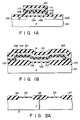
- a semiconductor device having a two-layer gate structure having a floating gate electrode and a control gate electrode has a structure as shown in Figs. 1A and 1B.
- Figs. 1A and 1B are sectional views of a semiconductor device, taken perpendicular to each other.
- This device comprises P-type semiconductor substrate 101, which has N-type source and drain regions 102 and 103 formed in surface regions thereof.
- Gate insulating film 106 is formed on channel region 104, which extends between source and drain regions 102 and 103, and as is shown in Fig. 1B, channel region 104 is isolated by field insulating layer 105.
- Floating gate electrode 107 consisting of polycrystalline silicon, for example, is formed on gate insulating film 106, and silicon oxide (SiO2) film 108 is formed on electrode 107, by thermal oxidization thereof.
- Silicon nitride (Si3N4) film 109 is formed on silicon oxide film 108, with silicon oxide film 110, in turn, being formed on film 109.
- Control gate electrode 111 consisting of polycrystalline silicon, is formed over floating gate electrode 107 via the three-layer insulating film consisting of silicon oxide film 108, silicon nitride film 109, and silicon oxide film 110.
- control gate electrode 11 The entire surface of the system, inclusive of control gate electrode 11, is then covered by insulating layer 112; for example, a silicon oxide film. In addition, although not shown, contact holes and aluminum leads are provided.
- floating gate electrode 107 is in an electrically floating state. Therefore, when a high voltage is applied to control gate electrode 111, an electric field is generated in gate insulating film 106 due to coupling between control and floating gate electrodes 111 and 107 and coupling between floating gate electrode 107 and channel region 104. At the same time, by applying a high voltage to drain region 103 hot electrons are generated in channel region 104 near the drain region. These hot electrons are injected into floating gate electrode 107 to obtain a state that data is stored.
- the insulating film between control and floating gate electrodes 111 and 107 has a three-layer structure consisting of silicon oxide film 108, silicon nitride film 109 and silicon oxide film 110.
- the three-layer insulating film compared to a single-layer insulating film, e.g., a silicon oxide film, has superior breakdown voltage for the same film thickness, so that it is advantageous over the single-layer film for thickness reduction. Even with the three-layer insulating film consisting of silicon oxide film 108, silicon nitride film 109 and silicon oxide film 110, there is a limitation imposed on the lower limit of the film thickness.
- silicon oxide films 108 and 110 should have a thickness of at least 40 angstroms.
- silicon nitride film 109 has an insufficient thickness, floating gate electrode 107 extending beneath film 109 is oxidized when forming silicon oxide film 110 by oxidization. For this reason, silicon nitride film 109 should have a thickness of at least 60 to 80 angstroms. Therefore, the three-layer insulating film should inevitably have a thickness of 140 to 160 angstroms.
- silicon nitride film 109 although it is excellent in the breakdown voltage, is very liable to capture electrons. Therefore, sometimes failure of erasing of data by ultraviolet ray illumination occurs, leading to deterioration of the erasing characteristics.
- An object of the invention is to provide a semiconductor device, which permits thickness reduction of the insulating film between the control and floating gate electrodes and precludes the drawback of deterioration of the erasing characteristics due to the use of the prior art silicon nitride film, thus permitting improvements of the erasing characteristics.
- a semiconductor device which comprises source and drain regions formed in a spaced-apart relation to each other in an isolated semiconductor substrate surface region, a first conductive layer formed over a channel region between the source and drain regions via a gate insulating film and constituting a floating gate electrode, a second insulating film formed on the first conductive layer and having a two-layer structure consisting of a silicon oxynitride film and a silicon oxide film, and a second conductive layer formed on the second insulating film and constituting a control gate electrode.
- the silicon oxynitride film traps less electrons, and electrons are difficultly trapped at the time of data erasing, so that it is possible to improve the erasing characteristics. Further, since less electrons are trapped, unlike the prior art insulating film utilizing the silicon nitride film, there is no need of providing any silicon oxide film on each side, and the two-layer structure consisting of the silicon film and silicon oxide film permits obtaining sufficient insulation and thickness reduction.
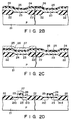
- Figs. 2A to 2E are sectional views for explaining a process of manufacture of one embodiment of the semiconductor device according to the invention.
- field insulating layer 22 for element isolation is formed by well-known techniques on the surface of silicon substrate 21 of P-type, for instance.
- Gate insulating film 23 is formed by thermal oxidization to a thickness of about 200 angstroms on the surface of semiconductor substrate 21 surrounded by field insulating layer 22.
- first polycrystalline silicon layer 24 is deposited to a thickness of approximately 4,000 angstroms on the entire surface of first polycrystalline silicon layer 24 by the CVD process.
- polycrystalline silicon layer 24 is doped with phosphorus or like impurities by means of ion implantation or thermal diffusion with POCl3 as source of diffusion.
- silicon oxynitride (SiN X O Y ) film 25 is deposited to a thickness of approximately 100 angstroms over the entire surface by a LPCVD process, in which NH3, SiH2Cl2 and N2O gases are supplied at respective rates of 500, 100 and 250 cc/min. in an atmosphere of 800°C and 200 Pa.
- first polycrystalline layer 24 which is to constitute a floating gate electrode of each EPROM cell is patterned in a direction perpendicular to the plane of the Figure (a section taken a plane perpendicular to the plane of Figs. 2A to 2E being shown in Fig. 3). Then, the surface of SiN X O Y film 25 and side surfaces of polycrystalline silicon layer 24 are oxidized by hydrogen combustion oxidization at an oxidization temperature of 950°C.
- second polycrystalline silicon layer 27 is deposited over the entire surface by the gas phase growth process, and phosphorus is implanted as an impurity into polycrystalline silicon layer 27. Second polycrystalline silicon layer 27 is removed in a peripheral circuit region, in which no EPROM cell transistor is formed.
- silicon oxide film 26, SiN X O Y film 25 and polycrystalline silicon layer 24 are successively selectively etched in the peripheral circuit area, in which no transistor is formed, with a resist pattern (not shown) formed as a mask to cover the region, in which the EPROM cell transistor is formed.
- a transistor pattern is thus formed as shown on the right side of Fig. 2D.
- a EPROM cell transistor formation region on the left side of Fig. 2D which is formed by covering a peripheral circuit transistor formation region of Fig.
- a EPROM cell transistor pattern is formed by successively respectively etching polycrystalline silicon layer 27, silicon oxide layer 26, SiN X O Y layer 25 and polycrystalline silicon layer 24. Subsequently, impurity implantation and annealing for the formation of the source and drain regions of the EPROM cell transistor and peripheral circuit transistor are done to form source and drain regions 21a and 21b of the EPROM cell transistor and source and drain regions 21c and 21d of the peripheral circuit transistor.
- silicon oxide film 26 and SiN X O Y film 25 in the peripheral circuit region are removed using RIE method (Reactive Ion Etching method), and then the entire surface is thermally oxidized to cover polycrystalline silicon films 24 and 27 with silicon oxide film 28.
- RIE method Reactive Ion Etching method
- a thick insulating layer (not shown) is formed over the entire surface by the usual method of manufacture of a MOS semiconductor device, and it is then formed at positions corresponding to the source and drain regions 21a and 21b of the EPROM cell transistor and source and drain regions 21c and 21d of the peripheral circuit transistor with contact holes. Aluminum leads are then formed in these contact holes, thus completing the EPROM cell transistor and peripheral circuit transistor.
- the insulating film between first polycrystalline silicon layer 24 serving as floating gate electrode and second polycrystalline silicon layer 27 serving as control gate electrode consists of a two-layer structure consisting of SiN X O Y layer 25 and silicon oxide film 26. Since the SiN X O Y film traps less electrons compared to the silicon nitride film, electrons are difficultly trapped compared to the prior art three-layer insulating film, in which a silicon nitride film is sandwiched between opposite side silicon oxide films, so that data-erasing characteristics can be improved.
- SiN X O Y film 25 which traps less electrons can prevent injection of electrons from second polycrystalline silicon layer 27 as control gate electrode or first polycrystalline silicon layer 24 as floating gate electrode.
- the impurity is liable to penetrate the polycrystalline silicon layer as gate electrode into the channel region to result in deterioration of the transistor characteristics.
- the insulating film consisting of SiN X O Y film 25 and silicon oxide film 26 is formed on polycrystalline as gate electrode of the peripheral circuit transistor.
- silicon oxide film 26 is formed on SiN X O Y film 25, it is of course possible to form SiN X O Y film on silicon oxide film 26.
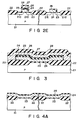
- the insulating film between the control and floating gate electrodes has a two-layer structure consisting of a SiN X O Y film and a silicon oxide film, will be described with reference to Figs. 4A to 4E.
- the gate electrode of the peripheral circuit transistor has been formed in a step of forming first polycrystalline silicon layer 24 as floating gate electrode of the EPROM cell transistor.
- the gate electrode of the peripheral circuit transistor is formed in a step of forming second polycrystalline silicon layer 27 as control gate electrode of the EPROM cell transistor. Now, this process will be described.
- field insulating layer 22 and gate insulating film 23 are formed by thermal oxidization on the surface of P-type silicon substrate 21, then first polycrystalline silicon layer 24 is formed by the LPCVD process on insulating films 22 and 23, and then SiN X O Y film 25 is formed as in the previous case by the LPCVD process on layer 24.
- the region in which the EPROM cell transistor is formed is covered with a resist (not shown), and with this resist as a mask SiN X O Y film 25, polycrystalline silicon layer 24 and gate oxide film 23 in the peripheral circuit transistor region are removed.
- a resist not shown
- this resist as a mask SiN X O Y film 25
- polycrystalline silicon layer 24 and gate oxide film 23 in the peripheral circuit transistor region are removed.
- Fig. 4C after washing the substrate surface silicon oxide film 26 is formed by thermal oxidization in the peripheral circuit transistor region.
- This silicon oxide film 26 is utilized as gate insulating film of the peripheral circuit transistor.
- silicon oxide film 26 is formed on SiN X O Y film 25 of the EPROM cell transistor formation region as well.
- second polycrystalline silicon layer 27 is deposited by the gas phase growth process in the EPROM cell transistor formation region and peripheral circuit transistor formation region. Phosphorus is then implanted as impurity into polycrystalline silicon layer 27.
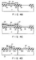
- the EPROM cell transistor formation region is covered with a resist pattern (not shown), and with this resist pattern as a mask polycrystalline silicon layer 27 in the peripheral circuit transistor formation region is selectively etched, thus forming a transistor pattern.
- the peripheral circuit transistor formation region is covered with another resist pattern (not shown), and with this resist pattern as a mask polycrystalline silicon layer 27, silicon oxide layer 26, SiN X O Y film 25, silicon oxide film 26 and SiN X O Y film and polycrystalline silicon film 24 are successively selectively etched, thus forming a EPROM cell transistor pattern.
- impurity ion implantation and diffusion are carried out to form source and drain regions 21a and 21b of the EPROM cell transistor and source and drain regions 21c and 21d of the peripheral circuit transistor.
- silicon oxide film 28 is formed by thermal oxidization to cover the surface of polycrystalline silicon layers 24 and 27. Then, as in the previous process a thick insulating layer is formed, and it is formed at positions corresponding to source and drain regions 21a and 21b of the EPROM cell transistor and source and drain regions 21c and 21d of the peripheral circuit transistor with contact holes, and aluminum leads are provided through these contact holes, thus completing the semiconductor device.
- silicon oxide film 26 is formed soon SiN X O Y film 25.
- SiN X O Y film 25 it is of course possible to form SiN X O Y film 25 on silicon oxide film 26.
- gate oxide film 23 of the EPROM cell and gate oxide film 26 of the peripheral circuit transistor are formed in separate steps, so that it is possible to increase the freedom of the device design; for instance, it is possible to vary the thickness of gate oxide film 23 of the EPROM cell transistor and gate oxide film 26 of the peripheral circuit transistor.
- different threshold voltages can be set for the EPROM cell and peripheral circuit transistors.
- a transistor having the same structure of the EPROM cell transistor can be formed on the peripheral circuit region, and then the floating gate electrode 24 and control gate electrode 27 of this transistor are short-circuited.
- the gate oxide film 23 of this transistor is different in thickness with gate oxide film 26 of the peripheral circuit transistor. Hence, transistors having different threshold voltages are formed on the peripheral circuit region.
- Fig. 5 shows a different embodiment of the semiconductor device according to the invention.
- the insulating film between floating and control gate electrodes 24 and 27 has been formed such that it has a two-layer structure having SiN X O Y film 25 as lower layer and silicon oxide film 26 as upper layer.
- the insulating film consists of silicon oxide film 26 as lower layer and SiN X O Y film 25 as upper layer.
- first polycrystalline silicon layer 24 serving as floating gate electrode is utilized as gate electrode of the peripheral circuit transistor.
- Fig. 6 shows a further embodiment of the invention.
- second polycrystalline silicon layer 27 serving as control gate electrode is utilized for the gate electrode of the peripheral circuit transistor.
- silicon oxide film 26 and SiN X O Y film 25 are utilized are utilized as gate oxide film of the peripheral circuit transistor.
Abstract
Description
- This invention relates to a semiconductor device and, more particularly, to a semiconductor device having a two-layer gate structure having a floating gate electrode and a control gate electrode.
- A semiconductor device having a two-layer gate structure having a floating gate electrode and a control gate electrode, e.g., EPROM, has a structure as shown in Figs. 1A and 1B.
- Figs. 1A and 1B are sectional views of a semiconductor device, taken perpendicular to each other. This device comprises P-
type semiconductor substrate 101, which has N-type source anddrain regions Gate insulating film 106 is formed onchannel region 104, which extends between source anddrain regions channel region 104 is isolated byfield insulating layer 105. Floatinggate electrode 107, consisting of polycrystalline silicon, for example, is formed ongate insulating film 106, and silicon oxide (SiO₂)film 108 is formed onelectrode 107, by thermal oxidization thereof. Silicon nitride (Si₃N₄)film 109 is formed onsilicon oxide film 108, withsilicon oxide film 110, in turn, being formed onfilm 109.Control gate electrode 111, consisting of polycrystalline silicon, is formed overfloating gate electrode 107 via the three-layer insulating film consisting ofsilicon oxide film 108,silicon nitride film 109, andsilicon oxide film 110. - The entire surface of the system, inclusive of control gate electrode 11, is then covered by
insulating layer 112; for example, a silicon oxide film. In addition, although not shown, contact holes and aluminum leads are provided. - In the semiconductor device of the above structure, floating
gate electrode 107 is in an electrically floating state. Therefore, when a high voltage is applied to controlgate electrode 111, an electric field is generated in gateinsulating film 106 due to coupling between control andfloating gate electrodes floating gate electrode 107 andchannel region 104. At the same time, by applying a high voltage to drainregion 103 hot electrons are generated inchannel region 104 near the drain region. These hot electrons are injected into floatinggate electrode 107 to obtain a state that data is stored. - In this state, a high electric field is generated between control and floating
gate electrodes - In the semiconductor device noted above, the insulating film between control and
floating gate electrodes silicon oxide film 108,silicon nitride film 109 andsilicon oxide film 110. The three-layer insulating film, compared to a single-layer insulating film, e.g., a silicon oxide film, has superior breakdown voltage for the same film thickness, so that it is advantageous over the single-layer film for thickness reduction. Even with the three-layer insulating film consisting ofsilicon oxide film 108,silicon nitride film 109 andsilicon oxide film 110, there is a limitation imposed on the lower limit of the film thickness. More specifically, if the film thickness ofsilicon oxide layers silicon oxide films silicon oxide films silicon nitride film 109 has an insufficient thickness, floatinggate electrode 107 extending beneathfilm 109 is oxidized when formingsilicon oxide film 110 by oxidization. For this reason,silicon nitride film 109 should have a thickness of at least 60 to 80 angstroms. Therefore, the three-layer insulating film should inevitably have a thickness of 140 to 160 angstroms. - In a further aspect,
silicon nitride film 109, although it is excellent in the breakdown voltage, is very liable to capture electrons. Therefore, sometimes failure of erasing of data by ultraviolet ray illumination occurs, leading to deterioration of the erasing characteristics. - An object of the invention is to provide a semiconductor device, which permits thickness reduction of the insulating film between the control and floating gate electrodes and precludes the drawback of deterioration of the erasing characteristics due to the use of the prior art silicon nitride film, thus permitting improvements of the erasing characteristics.
- According to the invention, there is provided a semiconductor device, which comprises source and drain regions formed in a spaced-apart relation to each other in an isolated semiconductor substrate surface region, a first conductive layer formed over a channel region between the source and drain regions via a gate insulating film and constituting a floating gate electrode, a second insulating film formed on the first conductive layer and having a two-layer structure consisting of a silicon oxynitride film and a silicon oxide film, and a second conductive layer formed on the second insulating film and constituting a control gate electrode.
- In the semiconductor device of this structure, the silicon oxynitride film traps less electrons, and electrons are difficultly trapped at the time of data erasing, so that it is possible to improve the erasing characteristics. Further, since less electrons are trapped, unlike the prior art insulating film utilizing the silicon nitride film, there is no need of providing any silicon oxide film on each side, and the two-layer structure consisting of the silicon film and silicon oxide film permits obtaining sufficient insulation and thickness reduction.
- This invention can be more fully understood from the following detailed description when taken in conjunction with the accompanying drawings, in which:
- Fig. 1A is a sectional view showing a prior art semiconductor device having a two-layer gate structure having a floating gate electrode and a control gate electrode;
- Fig. 1B is a sectional view taken along a plane perpendicular to the plane of section of Fig. 1 and showing the same prior art semiconductor device;
- Figs. 2A to 2E are sectional views showing steps of manufacture of a semiconductor device according to the invention;
- Fig. 3 is a sectional view taken along a plane perpendicular to the plane of Figs. 2A to 2E showing the semiconductor device according to the invention;
- Figs. 4A to 4E are sectional views showing steps of manufacture of a different semiconductor device according to the invention;
- Fig. 5 is a sectional view showing a further embodiment of the semiconductor device according to the invention; and
- Fig. 6 is a sectional view showing a still further embodiment of the semiconductor device according to the invention.
- Now, preferred embodiments of the invention will be described with reference to the drawings.
- Figs. 2A to 2E are sectional views for explaining a process of manufacture of one embodiment of the semiconductor device according to the invention.
- As shown in Fig. 2A,
field insulating layer 22 for element isolation is formed by well-known techniques on the surface ofsilicon substrate 21 of P-type, for instance.Gate insulating film 23 is formed by thermal oxidization to a thickness of about 200 angstroms on the surface ofsemiconductor substrate 21 surrounded byfield insulating layer 22. - Then, first
polycrystalline silicon layer 24 is deposited to a thickness of approximately 4,000 angstroms on the entire surface of firstpolycrystalline silicon layer 24 by the CVD process. Subsequently,polycrystalline silicon layer 24 is doped with phosphorus or like impurities by means of ion implantation or thermal diffusion with POCℓ₃ as source of diffusion. Then, silicon oxynitride (SiNXOY)film 25 is deposited to a thickness of approximately 100 angstroms over the entire surface by a LPCVD process, in which NH₃, SiH₂Cℓ₂ and N₂O gases are supplied at respective rates of 500, 100 and 250 cc/min. in an atmosphere of 800°C and 200 Pa. Then, firstpolycrystalline layer 24 which is to constitute a floating gate electrode of each EPROM cell is patterned in a direction perpendicular to the plane of the Figure (a section taken a plane perpendicular to the plane of Figs. 2A to 2E being shown in Fig. 3). Then, the surface of SiNXOY film 25 and side surfaces ofpolycrystalline silicon layer 24 are oxidized by hydrogen combustion oxidization at an oxidization temperature of 950°C. - Then, as shown in Fig. 2C, second
polycrystalline silicon layer 27 is deposited over the entire surface by the gas phase growth process, and phosphorus is implanted as an impurity intopolycrystalline silicon layer 27. Secondpolycrystalline silicon layer 27 is removed in a peripheral circuit region, in which no EPROM cell transistor is formed. - Then, as shown in Fig. 2D,
silicon oxide film 26, SiNXOY film 25 andpolycrystalline silicon layer 24 are successively selectively etched in the peripheral circuit area, in which no transistor is formed, with a resist pattern (not shown) formed as a mask to cover the region, in which the EPROM cell transistor is formed. A transistor pattern is thus formed as shown on the right side of Fig. 2D. Further, in a EPROM cell transistor formation region on the left side of Fig. 2D, which is formed by covering a peripheral circuit transistor formation region of Fig. 2D with a separate resist pattern (not shown), a EPROM cell transistor pattern is formed by successively respectively etchingpolycrystalline silicon layer 27,silicon oxide layer 26, SiNXOY layer 25 andpolycrystalline silicon layer 24. Subsequently, impurity implantation and annealing for the formation of the source and drain regions of the EPROM cell transistor and peripheral circuit transistor are done to form source anddrain regions drain regions - Then, as shown in Fig. 2E,
silicon oxide film 26 and SiNXOY film 25 in the peripheral circuit region are removed using RIE method (Reactive Ion Etching method), and then the entire surface is thermally oxidized to coverpolycrystalline silicon films silicon oxide film 28. - Then, a thick insulating layer (not shown) is formed over the entire surface by the usual method of manufacture of a MOS semiconductor device, and it is then formed at positions corresponding to the source and
drain regions drain regions - As has been shown, in this semiconductor device the insulating film between first
polycrystalline silicon layer 24 serving as floating gate electrode and secondpolycrystalline silicon layer 27 serving as control gate electrode consists of a two-layer structure consisting of SiNXOY layer 25 andsilicon oxide film 26. Since the SiNXOY film traps less electrons compared to the silicon nitride film, electrons are difficultly trapped compared to the prior art three-layer insulating film, in which a silicon nitride film is sandwiched between opposite side silicon oxide films, so that data-erasing characteristics can be improved. Further, with this semiconductor device, SiNXOY film 25 which traps less electrons can prevent injection of electrons from secondpolycrystalline silicon layer 27 as control gate electrode or firstpolycrystalline silicon layer 24 as floating gate electrode. Thus, there is no need of forming a three-layer structure as in the prior art, and the thickness of the insulating film can be reduced. - When
polycrystalline silicon layer 24 serving as gate electrode is reduced in thickness, at the time of the implantation of an impurity for forming the source and drain regions in the peripheral circuit region, the impurity is liable to penetrate the polycrystalline silicon layer as gate electrode into the channel region to result in deterioration of the transistor characteristics. In this semiconductor device, however, the insulating film consisting of SiNXOY film 25 andsilicon oxide film 26 is formed on polycrystalline as gate electrode of the peripheral circuit transistor. Thus, it is possible to prevent injection of impurity into the channel region and thus prevent deterioration of the characteristics of the peripheral circuit transistor. While in this embodimentsilicon oxide film 26 is formed on SiNXOY film 25, it is of course possible to form SiNXOY film onsilicon oxide film 26. - Now, a different process of manufacture of the semiconductor device, in which the insulating film between the control and floating gate electrodes has a two-layer structure consisting of a SiNXOY film and a silicon oxide film, will be described with reference to Figs. 4A to 4E.
- In previously mentioned structure, the gate electrode of the peripheral circuit transistor has been formed in a step of forming first
polycrystalline silicon layer 24 as floating gate electrode of the EPROM cell transistor. In this embodiment, the gate electrode of the peripheral circuit transistor is formed in a step of forming secondpolycrystalline silicon layer 27 as control gate electrode of the EPROM cell transistor. Now, this process will be described. - As shown in Fig. 4A,
field insulating layer 22 andgate insulating film 23 are formed by thermal oxidization on the surface of P-type silicon substrate 21, then firstpolycrystalline silicon layer 24 is formed by the LPCVD process on insulatingfilms layer 24. - Then, as shown in Fig. 4B, the region in which the EPROM cell transistor is formed is covered with a resist (not shown), and with this resist as a mask SiNXOY film 25,
polycrystalline silicon layer 24 andgate oxide film 23 in the peripheral circuit transistor region are removed. Subsequently, as shown in Fig. 4C, after washing the substrate surfacesilicon oxide film 26 is formed by thermal oxidization in the peripheral circuit transistor region. Thissilicon oxide film 26 is utilized as gate insulating film of the peripheral circuit transistor. During this thermal oxidization,silicon oxide film 26 is formed on SiNXOY film 25 of the EPROM cell transistor formation region as well. Subsequently, secondpolycrystalline silicon layer 27 is deposited by the gas phase growth process in the EPROM cell transistor formation region and peripheral circuit transistor formation region. Phosphorus is then implanted as impurity intopolycrystalline silicon layer 27. - Then, as shown in Fig. 4D, the EPROM cell transistor formation region is covered with a resist pattern (not shown), and with this resist pattern as a mask
polycrystalline silicon layer 27 in the peripheral circuit transistor formation region is selectively etched, thus forming a transistor pattern. Then, the peripheral circuit transistor formation region is covered with another resist pattern (not shown), and with this resist pattern as a maskpolycrystalline silicon layer 27,silicon oxide layer 26, SiNXOY film 25,silicon oxide film 26 and SiNXOY film andpolycrystalline silicon film 24 are successively selectively etched, thus forming a EPROM cell transistor pattern. Then, impurity ion implantation and diffusion are carried out to form source anddrain regions drain regions - Then, as shown in Fig 4E,
silicon oxide film 28 is formed by thermal oxidization to cover the surface of polycrystalline silicon layers 24 and 27. Then, as in the previous process a thick insulating layer is formed, and it is formed at positions corresponding to source anddrain regions drain regions - In this instance,
silicon oxide film 26 is formed soon SiNXOY film 25. However, it is of course possible to form SiNXOY film 25 onsilicon oxide film 26. - In this method of manufacture,
gate oxide film 23 of the EPROM cell andgate oxide film 26 of the peripheral circuit transistor are formed in separate steps, so that it is possible to increase the freedom of the device design; for instance, it is possible to vary the thickness ofgate oxide film 23 of the EPROM cell transistor andgate oxide film 26 of the peripheral circuit transistor. By providing different thicknesses ofgate oxide films gate electrode 24 andcontrol gate electrode 27 of this transistor are short-circuited. Thegate oxide film 23 of this transistor is different in thickness withgate oxide film 26 of the peripheral circuit transistor. Hence, transistors having different threshold voltages are formed on the peripheral circuit region. - Fig. 5 shows a different embodiment of the semiconductor device according to the invention. In the previous embodiment, the insulating film between floating and
control gate electrodes silicon oxide film 26 as upper layer. In this embodiment, the insulating film consists ofsilicon oxide film 26 as lower layer and SiNXOY film 25 as upper layer. Further, firstpolycrystalline silicon layer 24 serving as floating gate electrode is utilized as gate electrode of the peripheral circuit transistor. - Fig. 6 shows a further embodiment of the invention. In this instance, while a two-layer insulating film consisting of lower
silicon oxide film 26 and upper SiNXOY film 25 are formed, secondpolycrystalline silicon layer 27 serving as control gate electrode is utilized for the gate electrode of the peripheral circuit transistor. In this case,silicon oxide film 26 and SiNXOY film 25 are utilized are utilized as gate oxide film of the peripheral circuit transistor.
Claims (9)
Applications Claiming Priority (2)
| Application Number | Priority Date | Filing Date | Title |
|---|---|---|---|
| JP191548/87 | 1987-07-31 | ||
| JP62191548A JP2664685B2 (en) | 1987-07-31 | 1987-07-31 | Method for manufacturing semiconductor device |
Publications (3)
| Publication Number | Publication Date |
|---|---|
| EP0305741A2 true EP0305741A2 (en) | 1989-03-08 |
| EP0305741A3 EP0305741A3 (en) | 1990-05-16 |
| EP0305741B1 EP0305741B1 (en) | 1994-03-23 |
Family
ID=16276506
Family Applications (1)
| Application Number | Title | Priority Date | Filing Date |
|---|---|---|---|
| EP88112312A Expired - Lifetime EP0305741B1 (en) | 1987-07-31 | 1988-07-29 | Semiconductor device with floating gate |
Country Status (5)
| Country | Link |
|---|---|
| US (2) | US5063431A (en) |
| EP (1) | EP0305741B1 (en) |
| JP (1) | JP2664685B2 (en) |
| KR (1) | KR910007377B1 (en) |
| DE (1) | DE3888603T2 (en) |
Cited By (12)
| Publication number | Priority date | Publication date | Assignee | Title |
|---|---|---|---|---|
| EP0454051A2 (en) * | 1990-04-23 | 1991-10-30 | Kabushiki Kaisha Toshiba | Program element for use in redundancy technique for semiconductor memory device, and method of fabricating a semiconductor memory device having the same |
| EP0511628A2 (en) * | 1991-04-30 | 1992-11-04 | Texas Instruments Incorporated | Insulator for integrated circuits formed by high-pressure oxidation |
| EP0542575A2 (en) * | 1991-11-14 | 1993-05-19 | Fujitsu Limited | Method for fabricating a semiconductor memory device having a floating gate with improved insulation film quality |
| EP0610643A1 (en) * | 1993-02-11 | 1994-08-17 | STMicroelectronics S.r.l. | EEPROM cell and peripheral MOS transistor |
| US5397720A (en) * | 1994-01-07 | 1995-03-14 | The Regents Of The University Of Texas System | Method of making MOS transistor having improved oxynitride dielectric |
| US5478765A (en) * | 1994-05-04 | 1995-12-26 | Regents Of The University Of Texas System | Method of making an ultra thin dielectric for electronic devices |
| WO2000038237A1 (en) * | 1998-12-18 | 2000-06-29 | Koninklijke Philips Electronics N.V. | A method of manufacturing a semiconductor device |
| EP1111673A1 (en) * | 1995-05-10 | 2001-06-27 | STMicroelectronics S.r.l. | A method of manufacturing a MOS integrated circuit having components with different dielectrics |
| EP1162658A2 (en) * | 2000-06-09 | 2001-12-12 | SANYO ELECTRIC Co., Ltd. | Method of manufacturing semiconductor device |
| WO2003098694A1 (en) * | 2002-05-16 | 2003-11-27 | Infineon Technologies Ag | Layer arrangement and memory arrangement |
| EP1223621A3 (en) * | 2001-01-12 | 2005-08-17 | Infineon Technologies AG | Method of manufacturing of embedded non-volatile semiconductor memory cells |
| WO2009058486A1 (en) | 2007-10-29 | 2009-05-07 | Freescale Semiconductor Inc. | Method for integrating nvm circuitry with logic circuitry |
Families Citing this family (45)
| Publication number | Priority date | Publication date | Assignee | Title |
|---|---|---|---|---|
| JP2685966B2 (en) * | 1990-06-22 | 1997-12-08 | 株式会社東芝 | Nonvolatile semiconductor memory device |
| KR940009352B1 (en) * | 1990-07-09 | 1994-10-07 | 가부시끼가이샤 도시바 | Semiconductor device |
| JP2635809B2 (en) * | 1990-09-12 | 1997-07-30 | 株式会社東芝 | Semiconductor device and manufacturing method thereof |
| KR930007527B1 (en) * | 1990-09-22 | 1993-08-12 | 삼성전자 주식회사 | Nonvolatile semiconductor memory device having a storage cell array and circumference circuit and method for fabricating thereof |
| JP2679389B2 (en) * | 1990-10-12 | 1997-11-19 | 日本電気株式会社 | Data erasing method for nonvolatile semiconductor memory cell |
| KR930009131B1 (en) * | 1991-04-24 | 1993-09-23 | 삼성전자 주식회사 | Method of fabricating vlsi semiconductor memory device |
| JP2652108B2 (en) * | 1991-09-05 | 1997-09-10 | 三菱電機株式会社 | Field effect transistor and method of manufacturing the same |
| JPH0575133A (en) * | 1991-09-11 | 1993-03-26 | Rohm Co Ltd | Non-volatile memory |
| US5192872A (en) * | 1991-09-13 | 1993-03-09 | Micron Technology, Inc. | Cell structure for erasable programmable read-only memories |
| JPH05283710A (en) * | 1991-12-06 | 1993-10-29 | Intel Corp | High-voltage mos transistor and manufacture thereof |
| US5726087A (en) * | 1992-04-30 | 1998-03-10 | Motorola, Inc. | Method of formation of semiconductor gate dielectric |
| US5393683A (en) * | 1992-05-26 | 1995-02-28 | Micron Technology, Inc. | Method of making semiconductor devices having two-layer gate structure |
| KR960012303B1 (en) * | 1992-08-18 | 1996-09-18 | 삼성전자 주식회사 | Non-volatile semiconductor memory device and manufacturing thereof |
| DE69405438T2 (en) * | 1993-03-24 | 1998-04-02 | At & T Corp | Process for the formation of dielectric oxynitride layers in the production of integrated circuits |
| US5561319A (en) * | 1993-05-14 | 1996-10-01 | Lsi Logic Corporation | Integrated circuit structure including CMOS devices protected by patterned nitride passivation and method for the fabrication thereof |
| US5371028A (en) * | 1993-08-02 | 1994-12-06 | Chartered Semiconductor Manufacturing Pte Ltd. | Method for making single transistor non-volatile electrically alterable semiconductor memory device |
| DE4419762A1 (en) * | 1993-10-12 | 1995-04-20 | Hewlett Packard Co | Component with grown and deposited two-film gate oxide and method for its production |
| US5432749A (en) * | 1994-04-26 | 1995-07-11 | National Semiconductor Corporation | Non-volatile memory cell having hole confinement layer for reducing band-to-band tunneling |
| US6133620A (en) * | 1995-05-26 | 2000-10-17 | Semiconductor Energy Laboratory Co., Ltd. | Semiconductor device and process for fabricating the same |
| US5712208A (en) * | 1994-06-09 | 1998-01-27 | Motorola, Inc. | Methods of formation of semiconductor composite gate dielectric having multiple incorporated atomic dopants |
| JP3600326B2 (en) * | 1994-09-29 | 2004-12-15 | 旺宏電子股▲ふん▼有限公司 | Nonvolatile semiconductor memory device and manufacturing method thereof |
| US5780891A (en) * | 1994-12-05 | 1998-07-14 | Micron Technology, Inc. | Nonvolatile floating gate memory with improved interploy dielectric |
| JP2871530B2 (en) * | 1995-05-10 | 1999-03-17 | 日本電気株式会社 | Method for manufacturing semiconductor device |
| US6787844B2 (en) * | 1995-09-29 | 2004-09-07 | Nippon Steel Corporation | Semiconductor device including transistor with composite gate structure and transistor with single gate structure, and method for manufacturing the same |
| US5925907A (en) * | 1995-09-29 | 1999-07-20 | Nippon Steel Corporaition | Semiconductor device including transistor with composite gate structure and transistor with single gate structure |
| JPH10256539A (en) * | 1997-03-10 | 1998-09-25 | Fujitsu Ltd | Semiconductor device and manufacturing method thereof |
| US6258671B1 (en) * | 1997-05-13 | 2001-07-10 | Micron Technology, Inc. | Methods of providing spacers over conductive line sidewalls, methods of forming sidewall spacers over etched line sidewalls, and methods of forming conductive lines |
| US6020606A (en) * | 1998-03-20 | 2000-02-01 | United Silicon Incorporated | Structure of a memory cell |
| JP4212178B2 (en) * | 1999-03-12 | 2009-01-21 | 株式会社東芝 | Manufacturing method of semiconductor integrated circuit |
| US6677640B1 (en) * | 2000-03-01 | 2004-01-13 | Micron Technology, Inc. | Memory cell with tight coupling |
| JP3686318B2 (en) * | 2000-08-31 | 2005-08-24 | 松下電器産業株式会社 | Manufacturing method of semiconductor memory device |
| JP4096507B2 (en) * | 2000-09-29 | 2008-06-04 | 富士通株式会社 | Manufacturing method of semiconductor device |
| US20030232507A1 (en) * | 2002-06-12 | 2003-12-18 | Macronix International Co., Ltd. | Method for fabricating a semiconductor device having an ONO film |
| US7067439B2 (en) | 2002-06-14 | 2006-06-27 | Applied Materials, Inc. | ALD metal oxide deposition process using direct oxidation |
| US6893920B2 (en) * | 2002-09-12 | 2005-05-17 | Promos Technologies, Inc. | Method for forming a protective buffer layer for high temperature oxide processing |
| US7279003B2 (en) * | 2003-04-24 | 2007-10-09 | Medtronic Vascular, Inc. | Stent graft tapered spring |
| US8119210B2 (en) | 2004-05-21 | 2012-02-21 | Applied Materials, Inc. | Formation of a silicon oxynitride layer on a high-k dielectric material |
| US7837838B2 (en) | 2006-03-09 | 2010-11-23 | Applied Materials, Inc. | Method of fabricating a high dielectric constant transistor gate using a low energy plasma apparatus |
| US7645710B2 (en) | 2006-03-09 | 2010-01-12 | Applied Materials, Inc. | Method and apparatus for fabricating a high dielectric constant transistor gate using a low energy plasma system |
| US7678710B2 (en) | 2006-03-09 | 2010-03-16 | Applied Materials, Inc. | Method and apparatus for fabricating a high dielectric constant transistor gate using a low energy plasma system |
| JP4936790B2 (en) * | 2006-05-22 | 2012-05-23 | 株式会社東芝 | Semiconductor device |
| KR20080002030A (en) * | 2006-06-30 | 2008-01-04 | 삼성전자주식회사 | Method of forming a gate structure of non-volatile memory device |
| WO2008039845A2 (en) | 2006-09-26 | 2008-04-03 | Applied Materials, Inc. | Fluorine plasma treatment of high-k gate stack for defect passivation |
| KR100835430B1 (en) * | 2007-05-21 | 2008-06-04 | 주식회사 동부하이텍 | Method for forming dual gate electrode of semiconductor device |
| US8436411B2 (en) * | 2009-01-06 | 2013-05-07 | United Microelectronics Corp. | Non-volatile memory |
Citations (4)
| Publication number | Priority date | Publication date | Assignee | Title |
|---|---|---|---|---|
| WO1983002199A1 (en) * | 1981-12-14 | 1983-06-23 | Ncr Co | Non-volatile semiconductor memory device and manufacturing method therefor |
| EP0182198A2 (en) * | 1984-11-21 | 1986-05-28 | Rohm Corporation | Single transistor electrically programmable device and method |
| EP0187278A2 (en) * | 1984-12-07 | 1986-07-16 | Kabushiki Kaisha Toshiba | Semiconductor device and method for manufacturing the same |
| EP0195902A2 (en) * | 1985-03-25 | 1986-10-01 | International Business Machines Corporation | Dual electron injection structure and process with self-limiting oxidation barrier |
Family Cites Families (7)
| Publication number | Priority date | Publication date | Assignee | Title |
|---|---|---|---|---|
| US3992701A (en) * | 1975-04-10 | 1976-11-16 | International Business Machines Corporation | Non-volatile memory cell and array using substrate current |
| JPS577162A (en) * | 1980-06-17 | 1982-01-14 | Toshiba Corp | Nonvolatile semiconductor memory and manufacture therefor |
| US4477825A (en) * | 1981-12-28 | 1984-10-16 | National Semiconductor Corporation | Electrically programmable and erasable memory cell |
| JPS5955071A (en) * | 1982-09-24 | 1984-03-29 | Hitachi Micro Comput Eng Ltd | Non-volatile semiconductor device |
| US4601939A (en) * | 1983-09-20 | 1986-07-22 | International Business Machines Corporation | Composite insulator structure |
| JPS61212068A (en) * | 1985-03-16 | 1986-09-20 | Sony Corp | Semiconductor device |
| US4683554A (en) * | 1985-09-13 | 1987-07-28 | Ncr Corporation | Direct write nonvolatile memory cells |
-
1987
- 1987-07-31 JP JP62191548A patent/JP2664685B2/en not_active Expired - Fee Related
-
1988
- 1988-07-29 US US07/226,098 patent/US5063431A/en not_active Expired - Lifetime
- 1988-07-29 DE DE3888603T patent/DE3888603T2/en not_active Expired - Fee Related
- 1988-07-29 EP EP88112312A patent/EP0305741B1/en not_active Expired - Lifetime
- 1988-07-30 KR KR1019880009744A patent/KR910007377B1/en not_active IP Right Cessation
-
1990
- 1990-11-14 US US07/612,466 patent/US5034798A/en not_active Expired - Lifetime
Patent Citations (4)
| Publication number | Priority date | Publication date | Assignee | Title |
|---|---|---|---|---|
| WO1983002199A1 (en) * | 1981-12-14 | 1983-06-23 | Ncr Co | Non-volatile semiconductor memory device and manufacturing method therefor |
| EP0182198A2 (en) * | 1984-11-21 | 1986-05-28 | Rohm Corporation | Single transistor electrically programmable device and method |
| EP0187278A2 (en) * | 1984-12-07 | 1986-07-16 | Kabushiki Kaisha Toshiba | Semiconductor device and method for manufacturing the same |
| EP0195902A2 (en) * | 1985-03-25 | 1986-10-01 | International Business Machines Corporation | Dual electron injection structure and process with self-limiting oxidation barrier |
Cited By (25)
| Publication number | Priority date | Publication date | Assignee | Title |
|---|---|---|---|---|
| US5428572A (en) * | 1990-04-23 | 1995-06-27 | Kabushiki Kaisha Toshiba | Program element for use in redundancy technique for semiconductor memory device |
| EP0454051A3 (en) * | 1990-04-23 | 1993-04-21 | Kabushiki Kaisha Toshiba | Program element for use in redundancy technique for semiconductor memory device, and method of fabricating a semiconductor memory device having the same |
| EP0454051A2 (en) * | 1990-04-23 | 1991-10-30 | Kabushiki Kaisha Toshiba | Program element for use in redundancy technique for semiconductor memory device, and method of fabricating a semiconductor memory device having the same |
| EP0511628A2 (en) * | 1991-04-30 | 1992-11-04 | Texas Instruments Incorporated | Insulator for integrated circuits formed by high-pressure oxidation |
| EP0511628A3 (en) * | 1991-04-30 | 1993-09-22 | Texas Instruments Incorporated | Insulator for integrated circuits formed by high-pressure oxidation |
| EP0542575A2 (en) * | 1991-11-14 | 1993-05-19 | Fujitsu Limited | Method for fabricating a semiconductor memory device having a floating gate with improved insulation film quality |
| EP0542575A3 (en) * | 1991-11-14 | 1993-08-18 | Fujitsu Limited | Method for fabricating a semiconductor memory device having a floating gate with improved insulation film quality |
| US5497018A (en) * | 1991-11-14 | 1996-03-05 | Fujitsu Limited | Semiconductor memory device having a floating gate with improved insulation film quality |
| US5637520A (en) * | 1993-02-11 | 1997-06-10 | Sgs-Thomson Microelectronics S.R.L. | Process for fabricating integrated devices including flash-EEPROM memories and transistors |
| EP0610643A1 (en) * | 1993-02-11 | 1994-08-17 | STMicroelectronics S.r.l. | EEPROM cell and peripheral MOS transistor |
| US5397720A (en) * | 1994-01-07 | 1995-03-14 | The Regents Of The University Of Texas System | Method of making MOS transistor having improved oxynitride dielectric |
| US5541436A (en) * | 1994-01-07 | 1996-07-30 | The Regents Of The University Of Texas System | MOS transistor having improved oxynitride dielectric |
| US5478765A (en) * | 1994-05-04 | 1995-12-26 | Regents Of The University Of Texas System | Method of making an ultra thin dielectric for electronic devices |
| EP1111673A1 (en) * | 1995-05-10 | 2001-06-27 | STMicroelectronics S.r.l. | A method of manufacturing a MOS integrated circuit having components with different dielectrics |
| WO2000038237A1 (en) * | 1998-12-18 | 2000-06-29 | Koninklijke Philips Electronics N.V. | A method of manufacturing a semiconductor device |
| EP1162658A3 (en) * | 2000-06-09 | 2004-11-24 | SANYO ELECTRIC Co., Ltd. | Method of manufacturing semiconductor device |
| EP1162658A2 (en) * | 2000-06-09 | 2001-12-12 | SANYO ELECTRIC Co., Ltd. | Method of manufacturing semiconductor device |
| US6933197B2 (en) | 2000-06-09 | 2005-08-23 | Sanyo Electric Co., Ltd. | Method of manufacturing semiconductor device |
| EP1223621A3 (en) * | 2001-01-12 | 2005-08-17 | Infineon Technologies AG | Method of manufacturing of embedded non-volatile semiconductor memory cells |
| WO2003098694A1 (en) * | 2002-05-16 | 2003-11-27 | Infineon Technologies Ag | Layer arrangement and memory arrangement |
| US7713810B2 (en) | 2002-05-16 | 2010-05-11 | Infineon Technologies Ag | Method for fabricating a layer arrangement, layer arrangement and memory arrangement |
| WO2009058486A1 (en) | 2007-10-29 | 2009-05-07 | Freescale Semiconductor Inc. | Method for integrating nvm circuitry with logic circuitry |
| EP2206151A1 (en) * | 2007-10-29 | 2010-07-14 | Freescale Semiconductor, Inc. | Method for integrating nvm circuitry with logic circuitry |
| EP2206151A4 (en) * | 2007-10-29 | 2010-11-24 | Freescale Semiconductor Inc | Method for integrating nvm circuitry with logic circuitry |
| CN101842899B (en) * | 2007-10-29 | 2012-08-29 | 飞思卡尔半导体公司 | Method for integrating NVM circuitry with logic circuitry |
Also Published As
| Publication number | Publication date |
|---|---|
| US5034798A (en) | 1991-07-23 |
| US5063431A (en) | 1991-11-05 |
| KR910007377B1 (en) | 1991-09-25 |
| EP0305741B1 (en) | 1994-03-23 |
| EP0305741A3 (en) | 1990-05-16 |
| JP2664685B2 (en) | 1997-10-15 |
| DE3888603D1 (en) | 1994-04-28 |
| KR890003036A (en) | 1989-04-12 |
| JPS6436077A (en) | 1989-02-07 |
| DE3888603T2 (en) | 1994-08-04 |
Similar Documents
| Publication | Publication Date | Title |
|---|---|---|
| EP0305741A2 (en) | Semiconductor device with floating gate | |
| US5063172A (en) | Manufacture of a split-gate EPROM cell using polysilicon spacers | |
| KR100243497B1 (en) | Semiconductor device and method of manufacturing the same | |
| US5115288A (en) | Split-gate EPROM cell using polysilicon spacers | |
| KR100297306B1 (en) | Semiconductor device with field effect transistor and method of manufacturing the same | |
| US7374982B2 (en) | High voltage MOS transistor with gate extension | |
| KR100440698B1 (en) | Semiconductor device and method of fabricating the same | |
| JPH10189783A (en) | Semiconductor memory element and fabrication thereof | |
| US5658812A (en) | Nonvolatile semiconductor memory device and its manufacturing method | |
| KR940007654B1 (en) | Method of fabricating a nonvolatile semiconductor memory device | |
| JP2675572B2 (en) | Method for manufacturing semiconductor integrated circuit | |
| KR100222185B1 (en) | Method of manufacturing semiconductor device | |
| KR0146401B1 (en) | Method for manufacturing a semiconductor integrated circuit device having a stack gate structure | |
| JPH0851144A (en) | Partial components of semiconductor integrated circuits and manufacture thereof | |
| US6215142B1 (en) | Analog semiconductor device and method of fabricating the same | |
| JP2819972B2 (en) | Method for manufacturing semiconductor device | |
| EP0383011B1 (en) | Semiconductor non-volatile memory device | |
| EP0463511B1 (en) | Method of producing a split gate EPROM cell using polysilicon spacers | |
| US6046078A (en) | Semiconductor device fabrication with reduced masking steps | |
| JP2003243541A (en) | Manufacturing method for semiconductor integrated circuit apparatus | |
| JP2833389B2 (en) | Manufacturing method of nonvolatile semiconductor memory device | |
| JPH05251711A (en) | Semiconductor integrated circuit and its manufacture | |
| JPH1022404A (en) | Manufacture of split gate type semiconductor device | |
| JP3371169B2 (en) | Method for manufacturing semiconductor device | |
| JP2853793B2 (en) | Manufacturing method of memory element |
Legal Events
| Date | Code | Title | Description |
|---|---|---|---|
| PUAI | Public reference made under article 153(3) epc to a published international application that has entered the european phase |
Free format text: ORIGINAL CODE: 0009012 |
|
| 17P | Request for examination filed |
Effective date: 19880729 |
|
| AK | Designated contracting states |
Kind code of ref document: A2 Designated state(s): DE FR GB |
|
| PUAL | Search report despatched |
Free format text: ORIGINAL CODE: 0009013 |
|
| AK | Designated contracting states |
Kind code of ref document: A3 Designated state(s): DE FR GB |
|
| 17Q | First examination report despatched |
Effective date: 19920305 |
|
| GRAA | (expected) grant |
Free format text: ORIGINAL CODE: 0009210 |
|
| AK | Designated contracting states |
Kind code of ref document: B1 Designated state(s): DE FR GB |
|
| REF | Corresponds to: |
Ref document number: 3888603 Country of ref document: DE Date of ref document: 19940428 |
|
| ET | Fr: translation filed | ||
| PLBE | No opposition filed within time limit |
Free format text: ORIGINAL CODE: 0009261 |
|
| STAA | Information on the status of an ep patent application or granted ep patent |
Free format text: STATUS: NO OPPOSITION FILED WITHIN TIME LIMIT |
|
| 26N | No opposition filed | ||
| REG | Reference to a national code |
Ref country code: GB Ref legal event code: 746 Effective date: 19981015 |
|
| REG | Reference to a national code |
Ref country code: FR Ref legal event code: D6 |
|
| REG | Reference to a national code |
Ref country code: GB Ref legal event code: IF02 |
|
| PGFP | Annual fee paid to national office [announced via postgrant information from national office to epo] |
Ref country code: FR Payment date: 20050708 Year of fee payment: 18 |
|
| PGFP | Annual fee paid to national office [announced via postgrant information from national office to epo] |
Ref country code: DE Payment date: 20050721 Year of fee payment: 18 |
|
| PGFP | Annual fee paid to national office [announced via postgrant information from national office to epo] |
Ref country code: GB Payment date: 20050727 Year of fee payment: 18 |
|
| PG25 | Lapsed in a contracting state [announced via postgrant information from national office to epo] |
Ref country code: GB Free format text: LAPSE BECAUSE OF NON-PAYMENT OF DUE FEES Effective date: 20060729 |
|
| PG25 | Lapsed in a contracting state [announced via postgrant information from national office to epo] |
Ref country code: DE Free format text: LAPSE BECAUSE OF NON-PAYMENT OF DUE FEES Effective date: 20070201 |
|
| GBPC | Gb: european patent ceased through non-payment of renewal fee |
Effective date: 20060729 |
|
| REG | Reference to a national code |
Ref country code: FR Ref legal event code: ST Effective date: 20070330 |
|
| PG25 | Lapsed in a contracting state [announced via postgrant information from national office to epo] |
Ref country code: FR Free format text: LAPSE BECAUSE OF NON-PAYMENT OF DUE FEES Effective date: 20060731 |