EP0305203A2 - Method of carrying out heterogeneous catalytic chemical processes - Google Patents
Method of carrying out heterogeneous catalytic chemical processes Download PDFInfo
- Publication number
- EP0305203A2 EP0305203A2 EP88307936A EP88307936A EP0305203A2 EP 0305203 A2 EP0305203 A2 EP 0305203A2 EP 88307936 A EP88307936 A EP 88307936A EP 88307936 A EP88307936 A EP 88307936A EP 0305203 A2 EP0305203 A2 EP 0305203A2
- Authority
- EP
- European Patent Office
- Prior art keywords
- catalyst
- walls
- channels
- uniformly spaced
- substantially uniformly
- Prior art date
- Legal status (The legal status is an assumption and is not a legal conclusion. Google has not performed a legal analysis and makes no representation as to the accuracy of the status listed.)
- Granted
Links
- 238000000034 method Methods 0.000 title claims abstract description 120
- 230000003197 catalytic effect Effects 0.000 title claims abstract description 28
- 238000001311 chemical methods and process Methods 0.000 title claims abstract description 12
- 239000003054 catalyst Substances 0.000 claims abstract description 174
- 230000008569 process Effects 0.000 claims abstract description 78
- 239000012530 fluid Substances 0.000 claims abstract description 57
- 229930195733 hydrocarbon Natural products 0.000 claims abstract description 13
- 150000002430 hydrocarbons Chemical class 0.000 claims abstract description 13
- 238000000629 steam reforming Methods 0.000 claims abstract description 10
- 239000004215 Carbon black (E152) Substances 0.000 claims abstract description 3
- 238000006243 chemical reaction Methods 0.000 claims description 16
- UGFAIRIUMAVXCW-UHFFFAOYSA-N Carbon monoxide Chemical class [O+]#[C-] UGFAIRIUMAVXCW-UHFFFAOYSA-N 0.000 claims description 5
- 230000003647 oxidation Effects 0.000 claims description 5
- 238000007254 oxidation reaction Methods 0.000 claims description 5
- 230000036961 partial effect Effects 0.000 claims description 5
- 229910002090 carbon oxide Inorganic materials 0.000 claims description 4
- 150000001298 alcohols Chemical class 0.000 claims description 3
- 230000015572 biosynthetic process Effects 0.000 claims description 3
- 238000003786 synthesis reaction Methods 0.000 claims description 3
- UFHFLCQGNIYNRP-UHFFFAOYSA-N Hydrogen Chemical compound [H][H] UFHFLCQGNIYNRP-UHFFFAOYSA-N 0.000 claims description 2
- 229910052739 hydrogen Inorganic materials 0.000 claims description 2
- 239000001257 hydrogen Substances 0.000 claims description 2
- 230000009897 systematic effect Effects 0.000 claims description 2
- 238000002834 transmittance Methods 0.000 claims 2
- 108091006146 Channels Proteins 0.000 description 31
- 238000012546 transfer Methods 0.000 description 23
- 239000011111 cardboard Substances 0.000 description 14
- 238000002474 experimental method Methods 0.000 description 8
- 238000009826 distribution Methods 0.000 description 7
- 230000005540 biological transmission Effects 0.000 description 6
- 239000000463 material Substances 0.000 description 6
- 239000000919 ceramic Substances 0.000 description 5
- 239000011248 coating agent Substances 0.000 description 5
- 238000000576 coating method Methods 0.000 description 5
- 238000004519 manufacturing process Methods 0.000 description 5
- 239000002245 particle Substances 0.000 description 5
- PNEYBMLMFCGWSK-UHFFFAOYSA-N aluminium oxide Inorganic materials [O-2].[O-2].[O-2].[Al+3].[Al+3] PNEYBMLMFCGWSK-UHFFFAOYSA-N 0.000 description 4
- 239000007789 gas Substances 0.000 description 4
- 238000010438 heat treatment Methods 0.000 description 4
- OKKJLVBELUTLKV-UHFFFAOYSA-N Methanol Chemical compound OC OKKJLVBELUTLKV-UHFFFAOYSA-N 0.000 description 3
- 230000000694 effects Effects 0.000 description 3
- 238000011049 filling Methods 0.000 description 3
- 239000000123 paper Substances 0.000 description 3
- XLYOFNOQVPJJNP-UHFFFAOYSA-N water Substances O XLYOFNOQVPJJNP-UHFFFAOYSA-N 0.000 description 3
- QGZKDVFQNNGYKY-UHFFFAOYSA-N Ammonia Chemical compound N QGZKDVFQNNGYKY-UHFFFAOYSA-N 0.000 description 2
- UQSXHKLRYXJYBZ-UHFFFAOYSA-N Iron oxide Chemical compound [Fe]=O UQSXHKLRYXJYBZ-UHFFFAOYSA-N 0.000 description 2
- CPLXHLVBOLITMK-UHFFFAOYSA-N Magnesium oxide Chemical compound [Mg]=O CPLXHLVBOLITMK-UHFFFAOYSA-N 0.000 description 2
- 239000011149 active material Substances 0.000 description 2
- 239000003795 chemical substances by application Substances 0.000 description 2
- 238000001816 cooling Methods 0.000 description 2
- 238000005520 cutting process Methods 0.000 description 2
- 230000003247 decreasing effect Effects 0.000 description 2
- 239000000835 fiber Substances 0.000 description 2
- 238000005470 impregnation Methods 0.000 description 2
- 239000007791 liquid phase Substances 0.000 description 2
- 238000011068 loading method Methods 0.000 description 2
- 229910052749 magnesium Inorganic materials 0.000 description 2
- 239000011777 magnesium Substances 0.000 description 2
- -1 magnesium aluminate Chemical class 0.000 description 2
- 230000002035 prolonged effect Effects 0.000 description 2
- 230000002829 reductive effect Effects 0.000 description 2
- 230000002441 reversible effect Effects 0.000 description 2
- 239000011949 solid catalyst Substances 0.000 description 2
- 229910052596 spinel Inorganic materials 0.000 description 2
- 239000011029 spinel Substances 0.000 description 2
- 238000011282 treatment Methods 0.000 description 2
- IAYPIBMASNFSPL-UHFFFAOYSA-N Ethylene oxide Chemical compound C1CO1 IAYPIBMASNFSPL-UHFFFAOYSA-N 0.000 description 1
- LGRFSURHDFAFJT-UHFFFAOYSA-N Phthalic anhydride Natural products C1=CC=C2C(=O)OC(=O)C2=C1 LGRFSURHDFAFJT-UHFFFAOYSA-N 0.000 description 1
- 229910000831 Steel Inorganic materials 0.000 description 1
- WGLPBDUCMAPZCE-UHFFFAOYSA-N Trioxochromium Chemical compound O=[Cr](=O)=O WGLPBDUCMAPZCE-UHFFFAOYSA-N 0.000 description 1
- 229910021529 ammonia Inorganic materials 0.000 description 1
- 238000013459 approach Methods 0.000 description 1
- JHIWVOJDXOSYLW-UHFFFAOYSA-N butyl 2,2-difluorocyclopropane-1-carboxylate Chemical compound CCCCOC(=O)C1CC1(F)F JHIWVOJDXOSYLW-UHFFFAOYSA-N 0.000 description 1
- 238000001354 calcination Methods 0.000 description 1
- 238000001193 catalytic steam reforming Methods 0.000 description 1
- 229910010293 ceramic material Inorganic materials 0.000 description 1
- 229910000423 chromium oxide Inorganic materials 0.000 description 1
- 238000002485 combustion reaction Methods 0.000 description 1
- 230000004069 differentiation Effects 0.000 description 1
- 230000003292 diminished effect Effects 0.000 description 1
- 239000003546 flue gas Substances 0.000 description 1
- 239000000446 fuel Substances 0.000 description 1
- 239000011491 glass wool Substances 0.000 description 1
- 230000000670 limiting effect Effects 0.000 description 1
- 239000007788 liquid Substances 0.000 description 1
- 239000000395 magnesium oxide Substances 0.000 description 1
- 238000005259 measurement Methods 0.000 description 1
- WSFSSNUMVMOOMR-NJFSPNSNSA-N methanone Chemical compound O=[14CH2] WSFSSNUMVMOOMR-NJFSPNSNSA-N 0.000 description 1
- 229910000476 molybdenum oxide Inorganic materials 0.000 description 1
- PQQKPALAQIIWST-UHFFFAOYSA-N oxomolybdenum Chemical compound [Mo]=O PQQKPALAQIIWST-UHFFFAOYSA-N 0.000 description 1
- 238000012856 packing Methods 0.000 description 1
- 239000008188 pellet Substances 0.000 description 1
- 230000000704 physical effect Effects 0.000 description 1
- 230000001737 promoting effect Effects 0.000 description 1
- 230000003134 recirculating effect Effects 0.000 description 1
- 238000002407 reforming Methods 0.000 description 1
- 238000006057 reforming reaction Methods 0.000 description 1
- 230000001105 regulatory effect Effects 0.000 description 1
- 239000007787 solid Substances 0.000 description 1
- 230000003068 static effect Effects 0.000 description 1
- 239000010959 steel Substances 0.000 description 1
- 239000000126 substance Substances 0.000 description 1
- 238000012360 testing method Methods 0.000 description 1
- 239000011800 void material Substances 0.000 description 1
Images


Classifications
-
- C—CHEMISTRY; METALLURGY
- C01—INORGANIC CHEMISTRY
- C01B—NON-METALLIC ELEMENTS; COMPOUNDS THEREOF; METALLOIDS OR COMPOUNDS THEREOF NOT COVERED BY SUBCLASS C01C
- C01B3/00—Hydrogen; Gaseous mixtures containing hydrogen; Separation of hydrogen from mixtures containing it; Purification of hydrogen
- C01B3/02—Production of hydrogen or of gaseous mixtures containing a substantial proportion of hydrogen
- C01B3/32—Production of hydrogen or of gaseous mixtures containing a substantial proportion of hydrogen by reaction of gaseous or liquid organic compounds with gasifying agents, e.g. water, carbon dioxide, air
- C01B3/323—Catalytic reaction of gaseous or liquid organic compounds other than hydrocarbons with gasifying agents
-
- B—PERFORMING OPERATIONS; TRANSPORTING
- B01—PHYSICAL OR CHEMICAL PROCESSES OR APPARATUS IN GENERAL
- B01J—CHEMICAL OR PHYSICAL PROCESSES, e.g. CATALYSIS OR COLLOID CHEMISTRY; THEIR RELEVANT APPARATUS
- B01J12/00—Chemical processes in general for reacting gaseous media with gaseous media; Apparatus specially adapted therefor
- B01J12/007—Chemical processes in general for reacting gaseous media with gaseous media; Apparatus specially adapted therefor in the presence of catalytically active bodies, e.g. porous plates
-
- B—PERFORMING OPERATIONS; TRANSPORTING
- B01—PHYSICAL OR CHEMICAL PROCESSES OR APPARATUS IN GENERAL
- B01J—CHEMICAL OR PHYSICAL PROCESSES, e.g. CATALYSIS OR COLLOID CHEMISTRY; THEIR RELEVANT APPARATUS
- B01J19/00—Chemical, physical or physico-chemical processes in general; Their relevant apparatus
- B01J19/32—Packing elements in the form of grids or built-up elements for forming a unit or module inside the apparatus for mass or heat transfer
-
- C—CHEMISTRY; METALLURGY
- C01—INORGANIC CHEMISTRY
- C01B—NON-METALLIC ELEMENTS; COMPOUNDS THEREOF; METALLOIDS OR COMPOUNDS THEREOF NOT COVERED BY SUBCLASS C01C
- C01B3/00—Hydrogen; Gaseous mixtures containing hydrogen; Separation of hydrogen from mixtures containing it; Purification of hydrogen
- C01B3/02—Production of hydrogen or of gaseous mixtures containing a substantial proportion of hydrogen
- C01B3/06—Production of hydrogen or of gaseous mixtures containing a substantial proportion of hydrogen by reaction of inorganic compounds containing electro-positively bound hydrogen, e.g. water, acids, bases, ammonia, with inorganic reducing agents
- C01B3/12—Production of hydrogen or of gaseous mixtures containing a substantial proportion of hydrogen by reaction of inorganic compounds containing electro-positively bound hydrogen, e.g. water, acids, bases, ammonia, with inorganic reducing agents by reaction of water vapour with carbon monoxide
-
- C—CHEMISTRY; METALLURGY
- C01—INORGANIC CHEMISTRY
- C01B—NON-METALLIC ELEMENTS; COMPOUNDS THEREOF; METALLOIDS OR COMPOUNDS THEREOF NOT COVERED BY SUBCLASS C01C
- C01B3/00—Hydrogen; Gaseous mixtures containing hydrogen; Separation of hydrogen from mixtures containing it; Purification of hydrogen
- C01B3/02—Production of hydrogen or of gaseous mixtures containing a substantial proportion of hydrogen
- C01B3/32—Production of hydrogen or of gaseous mixtures containing a substantial proportion of hydrogen by reaction of gaseous or liquid organic compounds with gasifying agents, e.g. water, carbon dioxide, air
- C01B3/34—Production of hydrogen or of gaseous mixtures containing a substantial proportion of hydrogen by reaction of gaseous or liquid organic compounds with gasifying agents, e.g. water, carbon dioxide, air by reaction of hydrocarbons with gasifying agents
- C01B3/38—Production of hydrogen or of gaseous mixtures containing a substantial proportion of hydrogen by reaction of gaseous or liquid organic compounds with gasifying agents, e.g. water, carbon dioxide, air by reaction of hydrocarbons with gasifying agents using catalysts
- C01B3/384—Production of hydrogen or of gaseous mixtures containing a substantial proportion of hydrogen by reaction of gaseous or liquid organic compounds with gasifying agents, e.g. water, carbon dioxide, air by reaction of hydrocarbons with gasifying agents using catalysts the catalyst being continuously externally heated
-
- C—CHEMISTRY; METALLURGY
- C07—ORGANIC CHEMISTRY
- C07C—ACYCLIC OR CARBOCYCLIC COMPOUNDS
- C07C1/00—Preparation of hydrocarbons from one or more compounds, none of them being a hydrocarbon
- C07C1/02—Preparation of hydrocarbons from one or more compounds, none of them being a hydrocarbon from oxides of a carbon
-
- B—PERFORMING OPERATIONS; TRANSPORTING
- B01—PHYSICAL OR CHEMICAL PROCESSES OR APPARATUS IN GENERAL
- B01J—CHEMICAL OR PHYSICAL PROCESSES, e.g. CATALYSIS OR COLLOID CHEMISTRY; THEIR RELEVANT APPARATUS
- B01J2219/00—Chemical, physical or physico-chemical processes in general; Their relevant apparatus
- B01J2219/00049—Controlling or regulating processes
- B01J2219/00051—Controlling the temperature
- B01J2219/00074—Controlling the temperature by indirect heating or cooling employing heat exchange fluids
- B01J2219/00087—Controlling the temperature by indirect heating or cooling employing heat exchange fluids with heat exchange elements outside the reactor
- B01J2219/00094—Jackets
-
- B—PERFORMING OPERATIONS; TRANSPORTING
- B01—PHYSICAL OR CHEMICAL PROCESSES OR APPARATUS IN GENERAL
- B01J—CHEMICAL OR PHYSICAL PROCESSES, e.g. CATALYSIS OR COLLOID CHEMISTRY; THEIR RELEVANT APPARATUS
- B01J2219/00—Chemical, physical or physico-chemical processes in general; Their relevant apparatus
- B01J2219/18—Details relating to the spatial orientation of the reactor
- B01J2219/185—Details relating to the spatial orientation of the reactor vertical
-
- B—PERFORMING OPERATIONS; TRANSPORTING
- B01—PHYSICAL OR CHEMICAL PROCESSES OR APPARATUS IN GENERAL
- B01J—CHEMICAL OR PHYSICAL PROCESSES, e.g. CATALYSIS OR COLLOID CHEMISTRY; THEIR RELEVANT APPARATUS
- B01J2219/00—Chemical, physical or physico-chemical processes in general; Their relevant apparatus
- B01J2219/32—Details relating to packing elements in the form of grids or built-up elements for forming a unit of module inside the apparatus for mass or heat transfer
- B01J2219/322—Basic shape of the elements
- B01J2219/32203—Sheets
- B01J2219/32206—Flat sheets
-
- B—PERFORMING OPERATIONS; TRANSPORTING
- B01—PHYSICAL OR CHEMICAL PROCESSES OR APPARATUS IN GENERAL
- B01J—CHEMICAL OR PHYSICAL PROCESSES, e.g. CATALYSIS OR COLLOID CHEMISTRY; THEIR RELEVANT APPARATUS
- B01J2219/00—Chemical, physical or physico-chemical processes in general; Their relevant apparatus
- B01J2219/32—Details relating to packing elements in the form of grids or built-up elements for forming a unit of module inside the apparatus for mass or heat transfer
- B01J2219/322—Basic shape of the elements
- B01J2219/32203—Sheets
- B01J2219/3221—Corrugated sheets
-
- B—PERFORMING OPERATIONS; TRANSPORTING
- B01—PHYSICAL OR CHEMICAL PROCESSES OR APPARATUS IN GENERAL
- B01J—CHEMICAL OR PHYSICAL PROCESSES, e.g. CATALYSIS OR COLLOID CHEMISTRY; THEIR RELEVANT APPARATUS
- B01J2219/00—Chemical, physical or physico-chemical processes in general; Their relevant apparatus
- B01J2219/32—Details relating to packing elements in the form of grids or built-up elements for forming a unit of module inside the apparatus for mass or heat transfer
- B01J2219/322—Basic shape of the elements
- B01J2219/32203—Sheets
- B01J2219/32213—Plurality of essentially parallel sheets
- B01J2219/32217—Plurality of essentially parallel sheets with sheets having corrugations which intersect at an angle of 90 degrees
-
- B—PERFORMING OPERATIONS; TRANSPORTING
- B01—PHYSICAL OR CHEMICAL PROCESSES OR APPARATUS IN GENERAL
- B01J—CHEMICAL OR PHYSICAL PROCESSES, e.g. CATALYSIS OR COLLOID CHEMISTRY; THEIR RELEVANT APPARATUS
- B01J2219/00—Chemical, physical or physico-chemical processes in general; Their relevant apparatus
- B01J2219/32—Details relating to packing elements in the form of grids or built-up elements for forming a unit of module inside the apparatus for mass or heat transfer
- B01J2219/322—Basic shape of the elements
- B01J2219/32296—Honeycombs
-
- B—PERFORMING OPERATIONS; TRANSPORTING
- B01—PHYSICAL OR CHEMICAL PROCESSES OR APPARATUS IN GENERAL
- B01J—CHEMICAL OR PHYSICAL PROCESSES, e.g. CATALYSIS OR COLLOID CHEMISTRY; THEIR RELEVANT APPARATUS
- B01J2219/00—Chemical, physical or physico-chemical processes in general; Their relevant apparatus
- B01J2219/32—Details relating to packing elements in the form of grids or built-up elements for forming a unit of module inside the apparatus for mass or heat transfer
- B01J2219/324—Composition or microstructure of the elements
- B01J2219/32466—Composition or microstructure of the elements comprising catalytically active material
- B01J2219/32475—Composition or microstructure of the elements comprising catalytically active material involving heat exchange
-
- C—CHEMISTRY; METALLURGY
- C01—INORGANIC CHEMISTRY
- C01B—NON-METALLIC ELEMENTS; COMPOUNDS THEREOF; METALLOIDS OR COMPOUNDS THEREOF NOT COVERED BY SUBCLASS C01C
- C01B2203/00—Integrated processes for the production of hydrogen or synthesis gas
- C01B2203/08—Methods of heating or cooling
- C01B2203/0805—Methods of heating the process for making hydrogen or synthesis gas
- C01B2203/0833—Heating by indirect heat exchange with hot fluids, other than combustion gases, product gases or non-combustive exothermic reaction product gases
-
- Y—GENERAL TAGGING OF NEW TECHNOLOGICAL DEVELOPMENTS; GENERAL TAGGING OF CROSS-SECTIONAL TECHNOLOGIES SPANNING OVER SEVERAL SECTIONS OF THE IPC; TECHNICAL SUBJECTS COVERED BY FORMER USPC CROSS-REFERENCE ART COLLECTIONS [XRACs] AND DIGESTS
- Y02—TECHNOLOGIES OR APPLICATIONS FOR MITIGATION OR ADAPTATION AGAINST CLIMATE CHANGE
- Y02P—CLIMATE CHANGE MITIGATION TECHNOLOGIES IN THE PRODUCTION OR PROCESSING OF GOODS
- Y02P20/00—Technologies relating to chemical industry
- Y02P20/50—Improvements relating to the production of bulk chemicals
- Y02P20/52—Improvements relating to the production of bulk chemicals using catalysts, e.g. selective catalysts
-
- Y—GENERAL TAGGING OF NEW TECHNOLOGICAL DEVELOPMENTS; GENERAL TAGGING OF CROSS-SECTIONAL TECHNOLOGIES SPANNING OVER SEVERAL SECTIONS OF THE IPC; TECHNICAL SUBJECTS COVERED BY FORMER USPC CROSS-REFERENCE ART COLLECTIONS [XRACs] AND DIGESTS
- Y10—TECHNICAL SUBJECTS COVERED BY FORMER USPC
- Y10S—TECHNICAL SUBJECTS COVERED BY FORMER USPC CROSS-REFERENCE ART COLLECTIONS [XRACs] AND DIGESTS
- Y10S423/00—Chemistry of inorganic compounds
- Y10S423/09—Reaction techniques
- Y10S423/13—Catalyst contact
Definitions
- the present invention relates to a method of carrying out catalytic chemical processes under non-adiabatic conditions.
- a process fluid is contacted with a solid catalyst or a supported liquid phase catalyst which catalyses one or more reactions to form part of the process, the catalyst usually being arranged in one or more beds in one or more catalyst chambers in a catalytic reactor.
- catalytic processes processes of this kind.
- Carrying out a catalytic process under non-adiabatic conditions implies that during passage of the process fluid through the catalyst bed or beds heat is exchanged between the process fluid and some agent for heating or cooling, usually by convective heat exchange with a heat transmitting wall separating the process fluid from said agent.
- catalyst means any solid catalyst or supported liquid phase catalyst whether in one or more monolithic blocks or in the form of particles.
- catalyst bed means a bed in which any such catalyst is placed.
- Catalyst support body means a body which is usable for being transformed into a catalyst, e.g. by impregnation or coating, whether or not the thus treated body must undergo one or more further special treatments before reaching an active catalytic state, e.g. calcining or reduction.
- a catalyst as above defined may need a special treatment after being loaded into a catalyst chamber in order to reach an active state.
- fluid includes both liquid and gaseous substances.
- Chemical processes may be classified either as endothermic processes, which consume heat, or as exothermic ones, which produce heat.
- steam reforming of hydrocarbons may be mentioned as an example. It is usually performed at 400-950°C.
- the process is often performed in tubes containing a catalyst promoting the reaction(s).
- the tubes may be arranged in a radiant furnace chamber in which the combustion of a fuel supplies the necessary heat.
- the process may as an alternative be performed in a heat exchange reformer, e.g. as disclosed in European Patent Application No. 195,688.
- Exothermic catalytic processes are often performed at 200-600°C.
- partial oxidations may be mentioned, e.g. the manufacture of ethylene oxide, formaldehyde, or phthalic anhydride.
- methanation of carbon oxides are often performed in cooled tubular reactors.
- Some industrially important catalytic processes are reversible and exothermic, e.g. manufacture of ammonia or methanol. These processes are often performed while recirculating a part of the process gas through the catalyst beds as the conversion per pass is often fairly small.
- a number of different concepts are used among which some are non-adiabatic.
- a combination of pressure drop in the process fluid passing through the catalyst bed and heat transfer coefficient between the process fluid and the heat transmitting walls of the catalytic chambers will often represent the limiting process condition for throughput and yield with a given amount of catalyst as well as for process economy.
- a low pressure drop and a high heat transfer coefficient represent the desired process conditions.
- a low pressure drop will reduce the power required by the process plant irrespective of type of catalytic process.
- a high heat transfer coefficient is desirable for all types of non-adiabatic catalytic processes. For endothermic catalytic processes, a high heat transfer coefficient will increase the amount of heat supplied to the process fluid and, therefore, the reaction rate and the degree of conversion for a given amount of catalyst.
- U.S. Patent No. 3,785,620 describes bodies consisting of corrugated lamellae which are proposed to be used as static mixers.
- Sales pamphlets from Sulzer Brothers Ltd. describe bodies of similar form as the bodies of the U.S. Patents mentioned above,but in ceramic material,and propose to use them i.a. as catalyst support bodies.
- U.S. Patent No. 3,112,184 describes a method of making ceramic articles some of which have such characteristics as to fulfil the above features if made from a catalytic active material or used as support bodies. Such use is not, however, proposed in the description although it is stated that bodies of a somewhat similar configuration are used in such a way. It is proposed to use the articles for making heat exchangers transferring heat from streams flowing through some channels into streams flowing through others, but not to effect the heat transfer through a vessel wall.
- EP Patent Specification No. 0 025 308 discloses a process and an apparatus for endothermic steam reforming of hydrocarbons.
- a catalyst in the form of a structure comprising a stack of profiled plates is described.
- the structure is spaced from the walls of the catalyst chamber and has passages angled to the overall direction of flow in the catalyst chamber causing a process fluid to flow alternatively through the catalyst and for a significant length through a space between the structure and the heated walls of the catalyst chamber. Due to this flow pattern, the heated walls will show exended and successive areas of high temperature and low temperature caused by prolonged heating of some of the fluid, and decreasing flow rate in different areas along the reactor walls resulting in low heat transmission, followed by massive flow of the process fluid leaving the catalyst with a reduced temperature due to the reaction inside the catalyst channels.
- a very high transmission of heat from the walls of the catalyst chamber into the process fluid is particularly important when providing some of the heat for steam reforming of hydrocarbons by convective heat exchange between the process fluid and a flue gas in a heat exchange reformer.
- An essentially even temperature distribution along the heat transmitting walls is also of paramount importance for this process concept.
- None of the previously proposed methods has fully overcome the problem of simultaneously obtaining (1) a very low pressure drop in the process fluid passing through the catalyst bed, and (2) a high heat transfer coefficient between the wall(s) of the catalyst chamber and the process fluid, and further (3) having uniform or essentially uniform temperature distribution along the heat transmitting wall(s), and (4) efficient utilization of the total amount of catalyst.
- the object of the present invention is to provide a method which combines a very low pressure drop in the process fluid passing through the catalyst bed and a high and essentially uniform heat transfer coefficient between the wall or walls of the catalyst chamber and the process fluid, combined with an efficient utilization of the catalyst.
- the invention relates to a method of carrying out a heterogenous catalytic chemical process under non-adiabatic conditions by passing a stream of a process fluid in one overall flow direction through a catalyst contained in a catalyst chamber defined by walls two of which are substantially uniformly spaced,and transmitting heat through at least one of the two substantially uniformly spaced walls between the process fluids inside the catalyst chamber and a fluid outside the catalyst chamber, said catalyst having a structure of channels arranged in groups of substantially parallel channels causing the process fluid to be subdivided into a plurality of sub-streams having actual flow directions angled to the two uniformly spaced walls and to the overall flow direction, and changing direction whenever reaching one of the walls.
- the characteristic feature of this method is that the mass flow towards one of the two substantially uniformly spaced walls, at any cross section orthogonal to the overall flow direction, is approximately equal to the mass flow towards the other of said two walls, the flow direction of the sub-streams in one group of substantially parallel channels being different from that in the neighbouring group or groups of channels, and that the actual flow direction of any sub-stream is reflected whenever it reaches one of the two substantially uniformly spaced walls.
- the mass flow towards one of the two substantially uniformly spaced walls, at any cross section orthogonal to the overall flow direction is approximately equal to the mass flow towards the other of said two walls, the flow direction of the sub-streams in one group of substantially parallel channels being different from that in the neighbouring group or groups of channels, and that the actual flow direction of any sub-stream is reflected whenever it reaches one of the two substantially uniformly spaced walls.
- the efficiency of the method according to the present invention results from the immediate reversion of flow of any of the sub-streams whenever such a sub-stream reaches one of the heat transferring walls. No or only a minor flow of the fluid outside the channels and along the heat transferring walls is obtained.
- This flow pattern provides the least possible distance between cold spots caused by the fluid from the channels outlet and hot spots at the channel inlet.
- the structure of the catalyst chamber ensures uniform heating of the process fluid due to the frequent and close contact of said process fluid to the heat transferring wall or walls at the points of reflection.
- Another feature of the above mentioned catalyst chamber is the continuous and prolonged contact of the process fluid to the catalyst surface obtained by forced angular movement through the catalyst chamber, interrupted only by the reflection points at the heat transferring wall or walls.
- the ratio between the number of sub-streams directed towards each of the two walls can be between 1:100 and 100:1. It is, however, preferred that the ratio is between 1:10 and 10:1. Especially, it is preferred that the number of sub-streams directed towards one of the substantially uniformly spaced walls are approximately the same as the number of sub-streams directed towards the other of said walls.
- angles between the directions of actual flow through the catalyst and the direction of the overall flow through the catalyst bed are from 5 to 85°, preferably from 15 to 75°, and especially it is preferred that the angles are approximately 45°.
- a catalyst wherein the channels are arranged in layers which are not orthogonal to the overall direction of flow. Especially, it is preferred to use a catalyst wherein the channels are arranged in layers which are approximately parallel to the overall direction of flow.
- the manufacture of the catalyst is particularly simple when the layers are angled from 5 to 90° to the heat transmitting wall(s). It is especially preferred that the channels are arranged in layers which are approximately orthogonal to the heat transmitting walls.
- the two substantially uniformly spaced walls are coaxial cylindrical walls, the catalyst chamber being annular and the overall flow direction of the process fluid being parallel to the common axis of the cylindrical walls.
- the two substantially uniformly spaced walls are parallel and plane, the catalyst having the form of a prism with at least one pair of parallel sides.
- a process fluid can be brought to flow in sub-streams being arranged in sets of layers, the direction of the flow in one set of layers being essentially parallel and different from the direction in the neighbouring set or sets of layers, each set of layers comprising a small number of layers, preferably one or two.
- a simple way of obtaining such a flow is by means of a catalyst or catalyst support body comprising layers of sheets defining channels.
- the described flow pattern may e.g. be obtained by using as a catalyst or catalyst support body a stack composed of corrugated sheets, preferably alternating with plane sheets. Both types of sheet may, e.g., be made in a manner known per se and from a material compatible with the catalytic material and the chemical process.
- the stack may comprise one layer of channels in each set of either streaming direction and take the following form:
- the flow pattern characteristic for the method of the invention may also be obtained using only corrugated sheets and stacking them using alternately sheets of orientations A and B.
- a catalyst chamber complying with the method of the invention said two walls are coaxial cylindrical walls.
- a catalyst or catalyst support body of such form producing the flow pattern and heat transmission characterizing the method of the invention may as an example be manufactured by cutting stacks of sheets as described above and placing these stacks within two walls forming an annular mould. The stacks may e.g. be deformed sufficiently for them to attain the form of segments of a hollow cylindrical body and thus fit into the mould.
- the diameter of the two walls of the mould usually must differ slightly from the actual diameter of the corresponding walls of the catalyst chamber in order to allow for a possible different thermal expansion for catalyst or catalyst support body and the material of the catalyst chamber and to allow for desired slits between catalyst and walls.
- the sheets can be stacked orthogonally or obliquely relative to the walls of the above said mould and thus obliquely relative to the heat transmitting walls when the catalyst has become loaded into a catalyst chamber.
- the method of the invention is not restricted to the use of bodies prepared from stacks of sheets comprising corrugated sheets or, when using corrugated sheets, to use a special form of corrugation or to use the same form or size of corrugation for all corrugated sheets. Any other means of obtaining said flow pattern while obtaining a transmission of heat between the process fluid and the heat transmitting wall(s) is considered part of the invention when used in carrying out non-adiabatic catalytic processes.
- the flow pattern and heat transmission characterizing the method of the invention may e.g. be obtained using instead of sheets a great number of essentially identical pipes placed between two walls of approximately constant spacing of which at least one is heat transmitting.
- Each partial stream leaving a pipe will, when reaching one of the walls revert towards the other wall through neighbouring pipes of opposite orientation. If the wall is heat transmitting, this reversion causes a high heat transfer coefficient between process fluid and wall.
- the flow pattern and heat transfer characterizing the method of the invention may also be obtained e.g. using (instead of pipes) cylinders having two or more fluid passages extending axially therethrough from one end to the other.
- a catalyst support body providing the desired flow pattern and producing the desired heat transmission into a catalyst usable for carrying out the method of the invention such body may e.g. be impregnated or coated using an impregnation or coating technique and active materials known per se.
- the method of the invention may be utilized when carrying out a heterogeneous catalytic chemical process at non-adiabatic conditions and it is not restricted to any particular process.
- the process carried out can be an exothermic process, especially partial oxidation of hydrocarbons or alcohols, or hydrocarbon synthesis from carbon oxides and hydrogen.
- a coated catalyst support consisting of for instance glass wool paper, the coating consisting of, e.g., approximately 80% (w/w) molybdenum oxide and 20% (w/w) iron oxide promoted with chromium oxide.
- Synthesis of hydrocarbons from carbon oxides may be carried out by use of a coated catalyst support body consisting of, e.g. ceramic paper based on alumina fibers, the coating consisting of, e.g. 25-50% (w/w) Ni and the balance alumina.
- a coated catalyst support body consisting of, e.g. ceramic paper based on alumina fibers, the coating consisting of, e.g. 25-50% (w/w) Ni and the balance alumina.
- the process carried out can also be an endothermic process, especially steam reforming of hydrocarbons, preferably carried out in a heat exchange reformer.
- Such steam reforming may be carried out for instance by use of a coated catalyst support body consisting of, e.g., ceramic paper based on alumina fibers, the coating consisting of, e.g., 25% (w/w) Ni, the other main components being magnesia and alumina.
- a coated catalyst support body consisting of, e.g., ceramic paper based on alumina fibers, the coating consisting of, e.g., 25% (w/w) Ni, the other main components being magnesia and alumina.
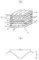
- Fig.1 shows a horizontal section through a reactor.
- the reactor has an annular catalyst chamber loaded with a catalyst suitable for carrying out the method of the invention.
- the process fluid flows down towards the catalyst.
- the catalyst body consists of corrugated sheets 14, 15 and plane sheets 16.
- the corrugated sheets have alternating orientations.
- the fluid channels 17 defined by the corrugated sheets 14 and the plane sheets 16 at either side lead fluid flowing down onto the catalyst body towards the outer wall 20 of the catalyst chamber, whereas the fluid channels 18 defined by the corrugated sheets 15 and the plane sheets 16 at either side lead the fluid towards the inner wall 19.
- all sheets are essentially orthogonal to the surface of both walls 19, 20.
- Fig. 2 shows a vertical section of the top part of the reactor and the catalyst body of Fig. 1 along the line a-a.
- the overall direction of flow is indicated by the arrows C. All layers of sub-streams and of the channels in which they flow are parallel to the overall direction of flow, C, and being ortogonal to the walls, the plane of a layer will coincide with the cut.
- the left part of the figure shows a section through a corrugated sheet 14 having sub-streams in channels 17 leading the sub-streams in the direction of the outer wall 20 whereas the right part of the figure shows a section through a corrugated sheet 15 having sub-streams in channels 18 leading the sub-streams in the direction of the inner wall 19.
- the flow directions of the sub-streams are indicated by arrows.
- the corrugated sheet lying beneath the sheet being sectioned and the plane sheet in between these sheets is indicated by dashed lines.
- the flow at this lower level has been indicated by dashed arrows.
- the flow reflection or "throwing back" upon reaching either of the walls is indi cated by shifting from full to dashed arrows at the reversal corresponding to the shifting from the plane of the figure to an underlying plane or vice versa.
- the annular catalyst chamber shown in Figs. 1 and 2 may,e.g.,be the catalyst chamber of a heat exchange reformer of the kind disclosed in published European Patent Application No. 195,688.
- Fig. 3 shows a section of a catalyst or catalyst support body which may be used in accordance with the invention.
- the section consists of a stack of essentially parallel sheets 14, 15, 16, the sheets 14 having a corrugation of orientation A, the sheets 15 having corrugations of orientations B, and the sheets 16 being plane.
- the stack has been made by stacking the sheets in the following order (from below): - one plane sheet 16 - one corrugated sheet 14, orientation A - one plane sheet 16 - one corrugated sheet 15, orientation B this sequence being continued throughout the stack.
- the corrugated sheets 14 define together with the plane sheets 16 below and on top of it essentially straight channels 17 and the corrugated sheets 15 define together with the plane sheets 16 below and on top of it essentially straight channels 18 the directions of the two systems of channels 17, 18 being different.
- the channels of either direction are arranged in essentially parallel layers.
- a section as shown in this figure may be made in the catalyst shown in Figs. 1 and 2, the overall flow direction being indicated by an arrow C e.g. one of the bisectors of the angles formed by the directions of the channels 17, 18. No deformation to accommodate to the loading in an annular catalyst chamber is shown.
- Fig. 4 shows an end view of a corrugated sheet seen along the corrugations.
- the figure indicates the dimensions E and L being characteristic for the corrugation.
- Fig. 5 shows a perspective view of another embodiment of a catalyst or catalyst support body suitable for carrying out the method of the invention, a part of the body having been taken away.
- This body consists of pipes 21, 22 having rectangular cross section.
- the pipes are stacked in piles 23, 24 with alternating orientation of the pipes, the piles 23 consisting of pipes 21 having an orientation different from that of the pipes 22 of the piles 24, providing for the flow pattern and heat transfer characteristic of the invention.
- Some of the piles 26 are indicated by dashed lines only, whereas only some of the pipes are shown in the foremost of the piles 27. Although the pipes of different piles are shown reaching the same level, this is not mandatory.
- Fig. 6. shows a vertical section of the body of Fig. 5.
- the body is placed between two walls 25 cutting one pile of pipes 21 and seen orthogonal to the plane of this pile.
- the pipes of the pile of pipes 22 laying just beneath the layer shown is indicated by dashed lines and the fluid flows are indicated by solid arrows and dashed arrows, respectively.
- the two walls 25 have essentially constant spacing. The reflection of the flows upon reaching these walls is indicated by the arrows.
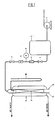
- Fig. 7 shows a sketch of the experimental set-up used to determine pressure drops and heat transfer coefficients for different models of catalyst bodies and catalyst particle beds.
- the reference numbers of Fig. 7 refer to the following items:
- Models 1 and 2 consisted of cross-arranged corrugated cardboard having a wave height, E, of 2.5 and 4.4 mm and having a plane sheet (a liner), i.e. made up like the body shown in Fig. 3.
- Model 3 consisted of cross-arranged corrugated cardboard having a wave height, E, of 2.1 mm and not having a liner.
- the outer surface per volume (S/V) is 1.5-2.5 times larger for the cross-arranged cardboard models than for the 5.3 x 5.1 mm cylinders.
- the catalyst activity per volume will be higher when using a cross-arranged catalyst than when using 5.3 x 5.1 mm catalyst cylinders, since the effectiveness factor of the reforming reaction is very low, typically less than 5%, in the bottom 80% of an ordinary tubular reformer and decreasing to less than 1% at the bottom, cf. J.R. Rostrup-Nielsen, Catalytic Steam Reforming, Springer Verlag, Berlin (1984), p. 69.
- the heat transfer and pressure drop properties of the models and of the catalyst cylinders and rings were determined in a 1000 mm long vertical channel having 55 x 300 mm rectangular horizontal cross section.
- the two walls of 300 x 1000 mm were two parallel plane radiators wherein hot water at 80°C was circulated.
- the cardboard models of dimensions 55 x 300 x 1000 mm were arranged having the planes of the sheet orthogonal to the heating surfaces and parallel to the direction of overall flow. The distance between the radiators could be increased at will as above said.
- Fig. 7 shows a sketch of the experimental set-up.
- a stream of air was passed down through the channel containing a cardboard model or catalyst cylinders or rings.
- the pressure drop across the "catalyst filling" and the heat transfer were determined.
- Valve (3) was opened and the reduction valve (4) and the control valve (7) were adjusted to obtain a reading on the pressure gauge (5) of 6 kg/cm2g and the flowmeter (6) showed a predetermined reading.
- the pressure drop across the catalyst filling (9) indicated by the U-tube manometer (10) was read.
- the temperatures of the catalyst or cardboard model and the hot water were recorded at 5-10 minute intervals until the recorded temperatures were stable.
- the difference between the hot water temperature at inlet and outlet was less than 2°C in all experiments. In the interpretation of the measurements it was assumed that the temperature was the same in all positions on the radiator walls.
- thermocouples were placed in the catalyst or models.
- thermocouples were placed in the centre plane between the two radiator walls.
- One thermocouple was placed on the centre line 10 mm from the bottom (gas outlet) and the remaining 12 were placed 10, 125, 250, and 500 mm from the top and in three different lateral positions: On the centre line, 95 mm to the left, and 95 mm to the right.
- thermocouples - except two - were placed in the centre plane orthogonal to the radiator walls.
- Five thermocouples were placed on the centre line 10 mm from the bottom (gas outlet) and 10, 125, 250, and 500 mm from the top.
- Six thermocouples were placed 19.5 mm from the centre line 125, 250, and 500 mm from the top, three on the near side of the centre plane between the two radiator walls and three on the far side.
- the ramaining two thermocouples were placed in the centre plane between the two radiator walls 250 mm from the top and 105 mm from the centre line, one to the left and one to the right.
- the heat transfer coefficients found for the cardboard models are higher than those found for the catalyst particles, provided that the slit width between the specimen and the wall does not exceed 1.2 mm.
- the pressure drop may be halved by replacing a catalyst or catalyst support body (model 3) having no liner by a catalyst or a catalyst support body (model 2) having a liner, having the same outer surface per volume (S/V) and yielding the same heat transfer coefficient when using the same slit width.
- corrugated sheets having straight or undulating corrugations
- a secondary corrugation optionally having other form or size and an orientation different from the primary corrugation may be used according to the invention.
Abstract
Description
- The present invention relates to a method of carrying out catalytic chemical processes under non-adiabatic conditions.
- In a heterogeneous catalytic chemical process, a process fluid is contacted with a solid catalyst or a supported liquid phase catalyst which catalyses one or more reactions to form part of the process, the catalyst usually being arranged in one or more beds in one or more catalyst chambers in a catalytic reactor. Throughout this specification by the term "catalytic processes" is meant processes of this kind.
- Carrying out a catalytic process under non-adiabatic conditions implies that during passage of the process fluid through the catalyst bed or beds heat is exchanged between the process fluid and some agent for heating or cooling, usually by convective heat exchange with a heat transmitting wall separating the process fluid from said agent.
- Throughout this specification the term "catalyst" means any solid catalyst or supported liquid phase catalyst whether in one or more monolithic blocks or in the form of particles. Similarly "catalyst bed" means a bed in which any such catalyst is placed. "Catalyst support body" means a body which is usable for being transformed into a catalyst, e.g. by impregnation or coating, whether or not the thus treated body must undergo one or more further special treatments before reaching an active catalytic state, e.g. calcining or reduction. Similarly, a catalyst as above defined may need a special treatment after being loaded into a catalyst chamber in order to reach an active state.
- The term fluid includes both liquid and gaseous substances.
- Chemical processes may be classified either as endothermic processes, which consume heat, or as exothermic ones, which produce heat.
- Among the endothermic catalytic processes of industrial importance and carried out at non-adiabatic conditions, steam reforming of hydrocarbons may be mentioned as an example. It is usually performed at 400-950°C. The process is often performed in tubes containing a catalyst promoting the reaction(s). The tubes may be arranged in a radiant furnace chamber in which the combustion of a fuel supplies the necessary heat. The process may as an alternative be performed in a heat exchange reformer, e.g. as disclosed in European Patent Application No. 195,688.
- Exothermic catalytic processes are often performed at 200-600°C. As examples of exothermic processes of industrial importance carried out under non-adiabatic conditions, partial oxidations may be mentioned, e.g. the manufacture of ethylene oxide, formaldehyde, or phthalic anhydride. Another example is methanation of carbon oxides. These processes are often performed in cooled tubular reactors.
- Some industrially important catalytic processes are reversible and exothermic, e.g. manufacture of ammonia or methanol. These processes are often performed while recirculating a part of the process gas through the catalyst beds as the conversion per pass is often fairly small. A number of different concepts are used among which some are non-adiabatic.
- A combination of pressure drop in the process fluid passing through the catalyst bed and heat transfer coefficient between the process fluid and the heat transmitting walls of the catalytic chambers will often represent the limiting process condition for throughput and yield with a given amount of catalyst as well as for process economy. A low pressure drop and a high heat transfer coefficient represent the desired process conditions. A low pressure drop will reduce the power required by the process plant irrespective of type of catalytic process. A high heat transfer coefficient is desirable for all types of non-adiabatic catalytic processes. For endothermic catalytic processes, a high heat transfer coefficient will increase the amount of heat supplied to the process fluid and, therefore, the reaction rate and the degree of conversion for a given amount of catalyst. For exothermic catalytic processes, a high heat transfer coefficient will reduce the temperature of the process fluid and, therefore, the reaction rate. Thus catalyst temperatures are more easily controlled and excess temperature resulting in catalyst damage are more readily averted. Likewise, undesired reactions, e.g. total oxidations are more easily avoided.
- For reversible exothermic catalytic processes, a high heat transfer coefficient between process fluid and cooling surfaces will result in (1) the temperatures of the process fluid being reduced and (2) the equilibrium being shifted towards a higher degree of conversion. The total effect will frequently be a higher yield.
- Using common commercial catalysts in the form of pellets, rings, or any other particulate form, it is not possible to increase the heat transfer coefficient between the walls of the catalyst chamber and the process fluid substantially without simultaneously increasing the pressure drop.
- Especially for the steam reforming process, this restriction has been felt. For some time, therefore, various methods using catalysts having non-particulate form have been described,aiming at obtaining simultaneously a low pressure drop and a high heat transfer coefficient.
- In the steam reforming process, the highest degree of conversion for a given amount of catalyst is obtained when operating at the highest temperature. For that reason the operation temperature often approaches the upper temperature limit for the tube material. A uniform temperature distribution along the heat transmitting walls will permit the highest average temperature for a given maximum temperature and is, therefore, highly desirable.
- Methods of obtaining some of these features have been described in the literature. Some of these methods utilize bodies which might be used as a catalyst or a catalyst support body if made from a suitable material but which, according to the description in the literature, are used otherwise. Below, references will be made to literature describing catalysts as well as bodies having some of the above features without being catalysts.
- U.S. Patent No. 3,785,620 describes bodies consisting of corrugated lamellae which are proposed to be used as static mixers.
- U.S. Patent No. 4,296,050 describes packing elements for an exchange column made from a plurality of corrugated plates.
- Sales pamphlets from Sulzer Brothers Ltd. describe bodies of similar form as the bodies of the U.S. Patents mentioned above,but in ceramic material,and propose to use them i.a. as catalyst support bodies.
- U.S. Patent No. 3,112,184 describes a method of making ceramic articles some of which have such characteristics as to fulfil the above features if made from a catalytic active material or used as support bodies. Such use is not, however, proposed in the description although it is stated that bodies of a somewhat similar configuration are used in such a way. It is proposed to use the articles for making heat exchangers transferring heat from streams flowing through some channels into streams flowing through others, but not to effect the heat transfer through a vessel wall.
- EP Patent Specification No. 0 025 308 discloses a process and an apparatus for endothermic steam reforming of hydrocarbons. A catalyst in the form of a structure comprising a stack of profiled plates is described. The structure is spaced from the walls of the catalyst chamber and has passages angled to the overall direction of flow in the catalyst chamber causing a process fluid to flow alternatively through the catalyst and for a significant length through a space between the structure and the heated walls of the catalyst chamber. Due to this flow pattern, the heated walls will show exended and successive areas of high temperature and low temperature caused by prolonged heating of some of the fluid, and decreasing flow rate in different areas along the reactor walls resulting in low heat transmission, followed by massive flow of the process fluid leaving the catalyst with a reduced temperature due to the reaction inside the catalyst channels.
- Thus, since the flow pattern according to the above mentioned EP-patent will not result in a uniform temperature distribution in the fluid entering the catalyst channels at a given level at the catalyst chamber, it is not possible to obtain a uniform catalyst utilization.
- A very high transmission of heat from the walls of the catalyst chamber into the process fluid is particularly important when providing some of the heat for steam reforming of hydrocarbons by convective heat exchange between the process fluid and a flue gas in a heat exchange reformer. An essentially even temperature distribution along the heat transmitting walls is also of paramount importance for this process concept.
- None of the previously proposed methods has fully overcome the problem of simultaneously obtaining (1) a very low pressure drop in the process fluid passing through the catalyst bed, and (2) a high heat transfer coefficient between the wall(s) of the catalyst chamber and the process fluid, and further (3) having uniform or essentially uniform temperature distribution along the heat transmitting wall(s), and (4) efficient utilization of the total amount of catalyst.
- The object of the present invention is to provide a method which combines a very low pressure drop in the process fluid passing through the catalyst bed and a high and essentially uniform heat transfer coefficient between the wall or walls of the catalyst chamber and the process fluid, combined with an efficient utilization of the catalyst.
- According to one aspect, the invention relates to a method of carrying out a heterogenous catalytic chemical process under non-adiabatic conditions by passing a stream of a process fluid in one overall flow direction through a catalyst contained in a catalyst chamber defined by walls two of which are substantially uniformly spaced,and transmitting heat through at least one of the two substantially uniformly spaced walls between the process fluids inside the catalyst chamber and a fluid outside the catalyst chamber, said catalyst having a structure of channels arranged in groups of substantially parallel channels causing the process fluid to be subdivided into a plurality of sub-streams having actual flow directions angled to the two uniformly spaced walls and to the overall flow direction, and changing direction whenever reaching one of the walls. The characteristic feature of this method is that the mass flow towards one of the two substantially uniformly spaced walls, at any cross section orthogonal to the overall flow direction, is approximately equal to the mass flow towards the other of said two walls, the flow direction of the sub-streams in one group of substantially parallel channels being different from that in the neighbouring group or groups of channels, and that the actual flow direction of any sub-stream is reflected whenever it reaches one of the two substantially uniformly spaced walls. In this manner there is obtained an essentially uniform temperature distribution along the heat transmitting wall or walls and an efficient utilization of the total amount of catalyst is thus made possible, i.e. that the amount of catalyst necessary for reaching a desired degree of conversion is diminished.
- The efficiency of the method according to the present invention results from the immediate reversion of flow of any of the sub-streams whenever such a sub-stream reaches one of the heat transferring walls. No or only a minor flow of the fluid outside the channels and along the heat transferring walls is obtained. This flow pattern provides the least possible distance between cold spots caused by the fluid from the channels outlet and hot spots at the channel inlet. The structure of the catalyst chamber ensures uniform heating of the process fluid due to the frequent and close contact of said process fluid to the heat transferring wall or walls at the points of reflection.
- Another feature of the above mentioned catalyst chamber is the continuous and prolonged contact of the process fluid to the catalyst surface obtained by forced angular movement through the catalyst chamber, interrupted only by the reflection points at the heat transferring wall or walls.
- The ratio between the number of sub-streams directed towards each of the two walls can be between 1:100 and 100:1. It is, however, preferred that the ratio is between 1:10 and 10:1. Especially, it is preferred that the number of sub-streams directed towards one of the substantially uniformly spaced walls are approximately the same as the number of sub-streams directed towards the other of said walls.
- It is preferred that the angles between the directions of actual flow through the catalyst and the direction of the overall flow through the catalyst bed are from 5 to 85°, preferably from 15 to 75°, and especially it is preferred that the angles are approximately 45°.
- It is preferred to use a catalyst wherein the channels are arranged in layers which are not orthogonal to the overall direction of flow. Especially, it is preferred to use a catalyst wherein the channels are arranged in layers which are approximately parallel to the overall direction of flow.
- The manufacture of the catalyst is particularly simple when the layers are angled from 5 to 90° to the heat transmitting wall(s). It is especially preferred that the channels are arranged in layers which are approximately orthogonal to the heat transmitting walls.
- An optimum combination of pressure drop and rate of heat transfer results when the streaming process fluid, when reaching whichever of the two uniformly spaced walls, is reflected or thrown back towards the opposite wall in a slit between the wall in question and the catalyst, the width of said slit being less than one fifth of the distance between the two uniformly spaced walls.
- In one embodiment of a catalyst chamber complying with the method of the invention,the two substantially uniformly spaced walls are coaxial cylindrical walls, the catalyst chamber being annular and the overall flow direction of the process fluid being parallel to the common axis of the cylindrical walls.
- In another embodiment of a catalyst chamber complying with the method of the invention, the two substantially uniformly spaced walls are parallel and plane, the catalyst having the form of a prism with at least one pair of parallel sides.
- The manufacture of a catalyst which may be used in the method of the invention, and the later loading thereof into a catalyst chamber is facilitated when using a catalyst wherein the catalyst is in the form of essentially identical bodies placed in the catalyst chamber in a systematic way.
- Complying with the method of the invention, a process fluid can be brought to flow in sub-streams being arranged in sets of layers, the direction of the flow in one set of layers being essentially parallel and different from the direction in the neighbouring set or sets of layers, each set of layers comprising a small number of layers, preferably one or two.
- A simple way of obtaining such a flow is by means of a catalyst or catalyst support body comprising layers of sheets defining channels.
- The described flow pattern may e.g. be obtained by using as a catalyst or catalyst support body a stack composed of corrugated sheets, preferably alternating with plane sheets. Both types of sheet may,e.g., be made in a manner known per se and from a material compatible with the catalytic material and the chemical process. The stack may comprise one layer of channels in each set of either streaming direction and take the following form:
- a. a corrugated sheet, orientation A
- b. a plane sheet
- c. a corrugated sheet, orientation B
- d. a plane sheet
- It is suitable to pass the process fluid through a catalyst bed wherein the channels are substantially straight, the angles between the actual directions of the sub-streams and the overall flow direction being 5° to 85°, preferably 15° to 75° and notably approximately 45°.
- The flow pattern characteristic for the method of the invention may also be obtained using only corrugated sheets and stacking them using alternately sheets of orientations A and B.
- In one of the above mentioned embodiments of a catalyst chamber complying with the method of the invention said two walls are coaxial cylindrical walls. This requires a catalyst in the form of a hollow cylindrical body. A catalyst or catalyst support body of such form producing the flow pattern and heat transmission characterizing the method of the invention may as an example be manufactured by cutting stacks of sheets as described above and placing these stacks within two walls forming an annular mould. The stacks may e.g. be deformed sufficiently for them to attain the form of segments of a hollow cylindrical body and thus fit into the mould. It should be borne in mind that the diameter of the two walls of the mould (corresponding to inner and outer wall, respectively, of a catalyst chamber) usually must differ slightly from the actual diameter of the corresponding walls of the catalyst chamber in order to allow for a possible different thermal expansion for catalyst or catalyst support body and the material of the catalyst chamber and to allow for desired slits between catalyst and walls.
- It is especially preferred to stack the sheets defining the stream pattern in the above said mould in such a manner that all flow directions become arranged in planes essentially parallel to the overall direction of flow when the catalyst has been loaded into a catalyst chamber.
- The sheets can be stacked orthogonally or obliquely relative to the walls of the above said mould and thus obliquely relative to the heat transmitting walls when the catalyst has become loaded into a catalyst chamber.
- The method of the invention is not restricted to the use of bodies prepared from stacks of sheets comprising corrugated sheets or, when using corrugated sheets, to use a special form of corrugation or to use the same form or size of corrugation for all corrugated sheets. Any other means of obtaining said flow pattern while obtaining a transmission of heat between the process fluid and the heat transmitting wall(s) is considered part of the invention when used in carrying out non-adiabatic catalytic processes.
- The flow pattern and heat transmission characterizing the method of the invention may e.g. be obtained using instead of sheets a great number of essentially identical pipes placed between two walls of approximately constant spacing of which at least one is heat transmitting. Stacking pipes of e.g. rectangular cross section and having length exeeding the distance between said two walls in such way as to obtain consecutive piles of pipes of alternating orientation, one leading towards one wall, the other towards the other wall,will provide for the desired flow pattern and give rise to only a small pressure drop. Each partial stream leaving a pipe will, when reaching one of the walls revert towards the other wall through neighbouring pipes of opposite orientation. If the wall is heat transmitting, this reversion causes a high heat transfer coefficient between process fluid and wall.
- The flow pattern and heat transfer characterizing the method of the invention may also be obtained e.g. using (instead of pipes) cylinders having two or more fluid passages extending axially therethrough from one end to the other.
- In order to transform a catalyst support body providing the desired flow pattern and producing the desired heat transmission into a catalyst usable for carrying out the method of the invention such body may e.g. be impregnated or coated using an impregnation or coating technique and active materials known per se.
- The method of the invention may be utilized when carrying out a heterogeneous catalytic chemical process at non-adiabatic conditions and it is not restricted to any particular process.
- The process carried out can be an exothermic process, especially partial oxidation of hydrocarbons or alcohols, or hydrocarbon synthesis from carbon oxides and hydrogen.
- For partial oxidation of hydrocarbons or alcohols one can, e.g. use a coated catalyst support consisting of for instance glass wool paper, the coating consisting of, e.g., approximately 80% (w/w) molybdenum oxide and 20% (w/w) iron oxide promoted with chromium oxide.
- Synthesis of hydrocarbons from carbon oxides may be carried out by use of a coated catalyst support body consisting of, e.g. ceramic paper based on alumina fibers, the coating consisting of, e.g. 25-50% (w/w) Ni and the balance alumina.
- The process carried out can also be an endothermic process, especially steam reforming of hydrocarbons, preferably carried out in a heat exchange reformer.
- Such steam reforming may be carried out for instance by use of a coated catalyst support body consisting of, e.g., ceramic paper based on alumina fibers, the coating consisting of, e.g., 25% (w/w) Ni, the other main components being magnesia and alumina.
- The invention is explained below with reference to the drawings, wherein
- Fig. 1 shows a horizontal section of a catalytic reactor comprising a catalyst bed usable for carrying out the method of the invention,
- Fig. 2 shows a vertical section of a part of the reactor of Fig. 1 taken along the line a-a,
- Fig. 3 shows a perspective view of a part of a catalyst or catalyst support body which may be used in carrying out the method of the invention,
- Fig. 4 shows a detail of the body shown in Fig. 3 on an enlarged scale,
- Fig. 5 shows another catalyst or catalyst support body for carrying out the method of the invention from which body a part has been taken away,
- Fig. 6 shows a vertical section of the body of Fig. 5 placed between two walls, and
- Fig. 7 shows a sketch of the experimental set-up used to determine pressure drops and heat transfer coefficients.
- The figures are simplified and do not show, e.g., thickness of plane or corrugated sheets.
- The difference between a catalyst and a catalyst support body cannot be discerned from the drawings and the figures do not attempt to make such differentiation.
- Fig.1 shows a horizontal section through a reactor. The reactor has an annular catalyst chamber loaded with a catalyst suitable for carrying out the method of the invention. The process fluid flows down towards the catalyst. The catalyst body consists of
corrugated sheets plane sheets 16. The corrugated sheets have alternating orientations. Thefluid channels 17 defined by thecorrugated sheets 14 and theplane sheets 16 at either side lead fluid flowing down onto the catalyst body towards theouter wall 20 of the catalyst chamber, whereas thefluid channels 18 defined by thecorrugated sheets 15 and theplane sheets 16 at either side lead the fluid towards theinner wall 19. In the catalyst shown in the figure, all sheets are essentially orthogonal to the surface of bothwalls - The slits between catalyst and walls are not shown in Fig. 1.
- Fig. 2 shows a vertical section of the top part of the reactor and the catalyst body of Fig. 1 along the line a-a. The overall direction of flow is indicated by the arrows C. All layers of sub-streams and of the channels in which they flow are parallel to the overall direction of flow, C, and being ortogonal to the walls, the plane of a layer will coincide with the cut. The left part of the figure shows a section through a
corrugated sheet 14 having sub-streams inchannels 17 leading the sub-streams in the direction of theouter wall 20 whereas the right part of the figure shows a section through acorrugated sheet 15 having sub-streams inchannels 18 leading the sub-streams in the direction of theinner wall 19. The flow directions of the sub-streams are indicated by arrows. The corrugated sheet lying beneath the sheet being sectioned and the plane sheet in between these sheets is indicated by dashed lines. The flow at this lower level has been indicated by dashed arrows. The flow reflection or "throwing back" upon reaching either of the walls is indi cated by shifting from full to dashed arrows at the reversal corresponding to the shifting from the plane of the figure to an underlying plane or vice versa. - The slits between catalyst and walls are not shown in Fig. 2.
- The annular catalyst chamber shown in Figs. 1 and 2 may,e.g.,be the catalyst chamber of a heat exchange reformer of the kind disclosed in published European Patent Application No. 195,688.
- At or near the edges of sheets against the inner and outer walls zones will occur with little net flow and locally small coefficient of heat transfer. Due to the turbulence caused by the reversal of flow at each or every two sheets or channels these zones will be very narrow and will be situated at distances corresponding to the height of one or two channels, typically a few mm each. The heat conductance in the wall or walls will effectively level out any temperature difference caused by such zones and no uneven temperature distribution will be noticeable.
- Fig. 3 shows a section of a catalyst or catalyst support body which may be used in accordance with the invention. The section consists of a stack of essentially
parallel sheets sheets 14 having a corrugation of orientation A, thesheets 15 having corrugations of orientations B, and thesheets 16 being plane. The stack has been made by stacking the sheets in the following order (from below):
- oneplane sheet 16
- onecorrugated sheet 14, orientation A
- oneplane sheet 16
- onecorrugated sheet 15, orientation B
this sequence being continued throughout the stack. - The
corrugated sheets 14 define together with theplane sheets 16 below and on top of it essentiallystraight channels 17 and thecorrugated sheets 15 define together with theplane sheets 16 below and on top of it essentiallystraight channels 18 the directions of the two systems ofchannels - A section as shown in this figure may be made in the catalyst shown in Figs. 1 and 2, the overall flow direction being indicated by an arrow C e.g. one of the bisectors of the angles formed by the directions of the
channels - Fig. 4 shows an end view of a corrugated sheet seen along the corrugations. The figure indicates the dimensions E and L being characteristic for the corrugation.
- Fig. 5 shows a perspective view of another embodiment of a catalyst or catalyst support body suitable for carrying out the method of the invention, a part of the body having been taken away. This body consists of
pipes piles piles 23 consisting ofpipes 21 having an orientation different from that of thepipes 22 of thepiles 24, providing for the flow pattern and heat transfer characteristic of the invention. Some of thepiles 26 are indicated by dashed lines only, whereas only some of the pipes are shown in the foremost of thepiles 27. Although the pipes of different piles are shown reaching the same level, this is not mandatory. - As explained with reference to Figs. 1 and 2, no uneven temperature distribution will be noticeable at the wall or walls when this embodiment is used for the process.
- Fig. 6. shows a vertical section of the body of Fig. 5. The body is placed between two
walls 25 cutting one pile ofpipes 21 and seen orthogonal to the plane of this pile. The pipes of the pile ofpipes 22 laying just beneath the layer shown is indicated by dashed lines and the fluid flows are indicated by solid arrows and dashed arrows, respectively. The twowalls 25 have essentially constant spacing. The reflection of the flows upon reaching these walls is indicated by the arrows. - Fig. 7 shows a sketch of the experimental set-up used to determine pressure drops and heat transfer coefficients for different models of catalyst bodies and catalyst particle beds.
The reference numbers of Fig. 7 refer to the following items: - (1) an air compressor, suction capacity ≧ 250 m³/hr.
- (2) an air vessel
- (3) a closing valve
- (4) a reduction valve
- (5) a precision pressure gauge, 0-15 kg/cm²g
- (6) a flowmeter 0-101 Nm³/hr. at 5 kg/cm²g, 15°C
- (7) a manually operated regulating valve
- (8) a model of a catalytic reactor having two
heat transmitting walls
The distance between the radiators could be modified by placing sheets of cardboard between one of the radiators and the laths. - (9) a catalyst body or catalyst bed
- (10) a U-tube manometer
- The invention and the advantages obtained are explained in more detail in the Example below.
- In an experimental set-up, models of catalysts providing the characteristics of the invention were compared with specimens of standard catalysts for steam reforming of hydrocarbons.
- Three models of cross-arranged corrugated catalyst support bodies were prepared from corrugated cardboard.
Models 1 and 2 consisted of cross-arranged corrugated cardboard having a wave height, E, of 2.5 and 4.4 mm and having a plane sheet (a liner), i.e. made up like the body shown in Fig. 3.Model 3 consisted of cross-arranged corrugated cardboard having a wave height, E, of 2.1 mm and not having a liner. For comparison, corresponding experiments were carried out using specimens of standard catalyst rings with OD/ID x H = 16.7/7.8 x 10.4 mm and standard catalyst cylinders with OD x H = 5.3 x 5.1 mm. - The data of the tested catalyst models and catalyst particles are stated in Table 1.
Table 1 Model 1 Model 2Model 3Rings Cylinders Filling Material Cardboard Cardboard Cardboard Ceramic magnesium aluminate spinel Ceramic magnesium aluminate spinel E, mm 2.5 4.4 2.1 - - L, mm 7.1 8.3 6.4 - - Corrugation Factor 1.3 1.5 1.3 - - OD, mm - - - 16.7 5.3 ID, mm - - - 7.8 - H, mm - - - 10.4 5.1 VOID, % 82 95 91 52.2 34.6 S/V, m²/m³ 1840 1140 1240 306 757 The dimensions E and L are indicated in Fig. 4. - It is noted that the outer surface per volume (S/V) is 1.5-2.5 times larger for the cross-arranged cardboard models than for the 5.3 x 5.1 mm cylinders. Thus, for the reforming process it is expected that the catalyst activity per volume will be higher when using a cross-arranged catalyst than when using 5.3 x 5.1 mm catalyst cylinders, since the effectiveness factor of the reforming reaction is very low, typically less than 5%, in the bottom 80% of an ordinary tubular reformer and decreasing to less than 1% at the bottom, cf. J.R. Rostrup-Nielsen, Catalytic Steam Reforming, Springer Verlag, Berlin (1984), p. 69.
- The heat transfer and pressure drop properties of the models and of the catalyst cylinders and rings were determined in a 1000 mm long vertical channel having 55 x 300 mm rectangular horizontal cross section. The two walls of 300 x 1000 mm were two parallel plane radiators wherein hot water at 80°C was circulated. The cardboard models of dimensions 55 x 300 x 1000 mm were arranged having the planes of the sheet orthogonal to the heating surfaces and parallel to the direction of overall flow. The distance between the radiators could be increased at will as above said.
- Fig. 7 shows a sketch of the experimental set-up. When carrying out an experiment, a stream of air was passed down through the channel containing a cardboard model or catalyst cylinders or rings. The pressure drop across the "catalyst filling" and the heat transfer were determined. Valve (3) was opened and the reduction valve (4) and the control valve (7) were adjusted to obtain a reading on the pressure gauge (5) of 6 kg/cm²g and the flowmeter (6) showed a predetermined reading. The pressure drop across the catalyst filling (9) indicated by the U-tube manometer (10) was read.
- The temperatures of the catalyst or cardboard model and the hot water were recorded at 5-10 minute intervals until the recorded temperatures were stable. The difference between the hot water temperature at inlet and outlet was less than 2°C in all experiments. In the interpretation of the measurements it was assumed that the temperature was the same in all positions on the radiator walls.
- The physical properties of the gas flow of the experiments are stated in the below Table 2.

- Thirteen thermocouples were placed in the catalyst or models.
- In the experiments using catalyst rings or cylinders, the distance between the radiator walls was 60 mm and all the thermocouples were placed in the centre plane between the two radiator walls. One thermocouple was placed on the
centre line 10 mm from the bottom (gas outlet) and the remaining 12 were placed 10, 125, 250, and 500 mm from the top and in three different lateral positions: On the centre line, 95 mm to the left, and 95 mm to the right. - In the experiments testing the cardboard models, all thermocouples - except two - were placed in the centre plane orthogonal to the radiator walls. Five thermocouples were placed on the
centre line 10 mm from the bottom (gas outlet) and 10, 125, 250, and 500 mm from the top. Six thermocouples were placed 19.5 mm from the centre line 125, 250, and 500 mm from the top, three on the near side of the centre plane between the two radiator walls and three on the far side. The ramaining two thermocouples were placed in the centre plane between the two radiator walls 250 mm from the top and 105 mm from the centre line, one to the left and one to the right. - The results obtained in the various experiments are summarized in Table 3.

- The pressure drops found for the cardboard models are lower, in some cases an order of magnitude lower than those found for the catalyst particles.
- The heat transfer coefficients found for the cardboard models are higher than those found for the catalyst particles, provided that the slit width between the specimen and the wall does not exceed 1.2 mm.
- Comparing the experimental results found using
models 1 and 2,it is seen that increasing the channel width leads to superior heat transfer and pressure drop properties. - Comparing the experimental results found for
models - In the above explanations referring to the figures and in the above Example, a number of embodiments of a catalyst complying with the method of the invention have been described in detail and the experimental results found when comparing three of these embodiments with a standard catalyst in a model experiment are stated. However, the results are considered illustrating only and not restricting the method of the invention to the specifically described embodiments. Any means of realizing the flow pattern and heat transferring characteristic of the invention and usable for carrying out a heterogeneous catalytic chemical process at non-adiabatic conditions is considered part of the invention only being restricted by the scope of the appended claims.
- Using stacks of corrugated sheets having undulating corrugations will fully comply with the method of the invention.
- Also corrugated sheets (having straight or undulating corrugations) may be given a secondary corrugation, optionally having other form or size and an orientation different from the primary corrugation may be used according to the invention.
- Further possibilities comprise apertured sheets or sheets having surface projections.
Claims (12)
and that the actual flow direction of any sub-stream is reflected whenever it reaches one of the two substantially uniformly spaced walls thereby leaving a channel and entering a channel of said neighbouring group of channels, so as to direct the sub-stream towards the other of those walls.
the actual flow direction of a process fluid passing from the entrance to the exit of the process chamber is reflected whenever it reaches one of the two substantially uniformly spaced walls thereby leaving a channel and entering a channel of said neighbouring group of channels, so as to direct the fluid towards the other of those walls.
Applications Claiming Priority (2)
| Application Number | Priority Date | Filing Date | Title |
|---|---|---|---|
| DK4481/87 | 1987-08-27 | ||
| DK448187A DK156701C (en) | 1987-08-27 | 1987-08-27 | PROCEDURE FOR IMPLEMENTING Heterogeneous CATALYTIC CHEMICAL REACTIONS |
Publications (3)
| Publication Number | Publication Date |
|---|---|
| EP0305203A2 true EP0305203A2 (en) | 1989-03-01 |
| EP0305203A3 EP0305203A3 (en) | 1989-08-16 |
| EP0305203B1 EP0305203B1 (en) | 1993-11-10 |
Family
ID=8133920
Family Applications (1)
| Application Number | Title | Priority Date | Filing Date |
|---|---|---|---|
| EP88307936A Expired - Lifetime EP0305203B1 (en) | 1987-08-27 | 1988-08-26 | Method of carrying out heterogeneous catalytic chemical processes |
Country Status (7)
| Country | Link |
|---|---|
| US (1) | US4985230A (en) |
| EP (1) | EP0305203B1 (en) |
| JP (1) | JP2592662B2 (en) |
| CA (1) | CA1304215C (en) |
| DE (1) | DE3885545T2 (en) |
| DK (1) | DK156701C (en) |
| NO (1) | NO170837C (en) |
Cited By (17)
| Publication number | Priority date | Publication date | Assignee | Title |
|---|---|---|---|---|
| WO1997024176A1 (en) * | 1995-12-27 | 1997-07-10 | International Fuel Cell Corporation | Compact hydrocarbon fuel gas reformer assemblage |
| WO1997025752A1 (en) * | 1996-01-11 | 1997-07-17 | International Fuel Cells Corporation | Compact selective oxidizer assemblage for fuel cell power plant |
| WO1999062629A1 (en) * | 1998-05-29 | 1999-12-09 | Abb Lummus Global Inc. | Structured packing and element therefor |
| WO2000005168A1 (en) * | 1998-07-21 | 2000-02-03 | Haldor Topsøe A/S | Synthesis gas production by steam reforming |
| WO2000032513A1 (en) * | 1998-12-01 | 2000-06-08 | Johnson Matthey Public Limited Company | Reactor and process for removal of carbon monoxide from hydrogen |
| EP1010462A1 (en) * | 1998-12-19 | 2000-06-21 | DaimlerChrysler AG | Device for the catalytic conversion of a feedstock, particularely of a gas mixture |
| WO2001010773A1 (en) * | 1999-08-07 | 2001-02-15 | Lattice Intellectual Property Ltd. | Compact reactor |
| WO2002007872A1 (en) * | 2000-07-25 | 2002-01-31 | Shell Internationale Research Maatschappij B.V. | A reactor comprising a packed bed of supported catalyst or supported catalyst precursor, and a use of the reactor |
| EP1254705A1 (en) * | 2001-04-26 | 2002-11-06 | Sulzer Chemtech AG | Column reactor with packing and heat transfer means |
| WO2003006149A1 (en) * | 2001-07-11 | 2003-01-23 | Gtl Microsystems Ag | Catalytic reactor |
| US6667017B2 (en) | 1999-10-15 | 2003-12-23 | Abb Lummus Global, Inc. | Process for removing environmentally harmful compounds |
| US6712982B2 (en) | 2001-05-29 | 2004-03-30 | Rentech, Inc. | Method of removing catalyst particles from wax |
| US7087192B2 (en) | 2002-09-26 | 2006-08-08 | Haldor Topsoe A/S | Process for the preparation of synthesis gas |
| US7090789B2 (en) | 2003-02-05 | 2006-08-15 | Haldor Topsoe A/S | Process and catalyst for treatment of synthesis gas |
| US7094363B2 (en) | 2002-09-26 | 2006-08-22 | Haldor Topsoe A/S | Process for the preparation of a synthesis gas |
| WO2022106058A1 (en) | 2020-11-19 | 2022-05-27 | L'air Liquide Societe Anonyme Pour L'etude Et L'exploitation Des Procedes Georges Claude | Reforming reactor comprising reformer tubes with enlarged outer surface area and structured catalyst |
| EP4155259A1 (en) | 2021-09-22 | 2023-03-29 | L'Air Liquide Société Anonyme pour l'Etude et l'Exploitation des Procédés Georges Claude | Method for producing synthesis gas with reduced steam export |
Families Citing this family (39)
| Publication number | Priority date | Publication date | Assignee | Title |
|---|---|---|---|---|
| JPH084104Y2 (en) * | 1990-03-23 | 1996-02-07 | 秀雄 亀山 | Exothermic reactor that doubles as a heat exchanger |
| FR2710047B1 (en) * | 1993-09-17 | 1995-10-13 | Atochem Elf Sa | Process for the continuous preparation of aluminum nitride by carbonitriding alumina in a flow-bed reactor. |
| JP3599370B2 (en) * | 1994-05-23 | 2004-12-08 | 日本碍子株式会社 | Hydrogen production equipment |
| DE19524158A1 (en) * | 1995-07-03 | 1997-01-09 | Degussa | Process for the production of hydrocyanic acid |
| US6479428B1 (en) | 1998-07-27 | 2002-11-12 | Battelle Memorial Institute | Long life hydrocarbon conversion catalyst and method of making |
| US6616909B1 (en) * | 1998-07-27 | 2003-09-09 | Battelle Memorial Institute | Method and apparatus for obtaining enhanced production rate of thermal chemical reactions |
| US6440895B1 (en) | 1998-07-27 | 2002-08-27 | Battelle Memorial Institute | Catalyst, method of making, and reactions using the catalyst |
| IL141170A (en) * | 1998-09-12 | 2004-07-25 | Degussa | Method for carrying out gas-liquid reactions and corresponding flow reactor |
| DE19936276A1 (en) | 1999-08-02 | 2001-02-08 | Basf Ag | Device and method for the isothermal implementation of heterogeneously catalyzed three-phase reactions |
| DE60014671T2 (en) * | 1999-08-17 | 2006-02-23 | Battelle Memorial Institute, Richland | CATALYST STRUCTURE AND FISCHER TROPSCH SYNTHESIS METHOD |
| CA2381154C (en) * | 1999-08-17 | 2009-02-03 | Battelle Memorial Institute | Chemical reactor and method for catalytic gas phase reactions |
| US6607678B2 (en) | 1999-08-17 | 2003-08-19 | Battelle Memorial Institute | Catalyst and method of steam reforming |
| US6488838B1 (en) * | 1999-08-17 | 2002-12-03 | Battelle Memorial Institute | Chemical reactor and method for gas phase reactant catalytic reactions |
| US6451864B1 (en) | 1999-08-17 | 2002-09-17 | Battelle Memorial Institute | Catalyst structure and method of Fischer-Tropsch synthesis |
| CN1235675C (en) * | 2000-01-11 | 2006-01-11 | 阿山特斯有限公司 | Catalytic reactor |
| FR2812221B1 (en) * | 2000-07-28 | 2003-04-04 | Butachimie | NEW CATALYTIC DEVICE FOR IMPLEMENTING A REACTION IN A HIGH-TEMPERATURE GASEOUS MEDIUM |
| ATE342480T1 (en) * | 2000-07-28 | 2006-11-15 | Honda Motor Co Ltd | MULTIPURPOSE MICROCOMPONENT WITH MICROCHANNELS |
| DE10057418A1 (en) * | 2000-11-20 | 2002-06-20 | Emitec Emissionstechnologie | Reactor unit used for steam reforming a gas mixture stream containing hydrocarbons in fuel cells has sheet layers with heating fluid channels and gas mixture channels arranged to form a specified angle |
| DE10110465B4 (en) * | 2001-03-05 | 2005-12-08 | Vodafone Pilotentwicklung Gmbh | reactor |
| EP1413547A1 (en) * | 2002-09-26 | 2004-04-28 | Haldor Topsoe A/S | Process for the production of synthesis gas |
| AU2003297883A1 (en) * | 2002-12-19 | 2004-07-29 | Precision Combustion, Inc. | Method for oxidative reforming |
| DE10317451A1 (en) * | 2003-04-16 | 2004-11-18 | Degussa Ag | Reactor for heterogeneously catalyzed reactions |
| US7208136B2 (en) * | 2003-05-16 | 2007-04-24 | Battelle Memorial Institute | Alcohol steam reforming catalysts and methods of alcohol steam reforming |
| US7608344B2 (en) * | 2003-07-30 | 2009-10-27 | Corning Incorporated | Metal honeycomb substrates for chemical and thermal applications |
| WO2005080261A1 (en) * | 2004-02-17 | 2005-09-01 | Modine Manufacturing Company | Integrated fuel processor for distributed hydrogen production |
| US7306781B2 (en) * | 2004-07-09 | 2007-12-11 | Catacel Corp. | Hydrogen generator |
| KR100966844B1 (en) * | 2004-11-23 | 2010-06-29 | 조나단 제이 페인스테인 | Reactor with jet impingment heat transfer |
| DE102005020943A1 (en) * | 2005-05-04 | 2006-11-09 | Linde Ag | Process and reactor for carrying out endothermic catalytic reactions |
| US20070175094A1 (en) * | 2006-01-30 | 2007-08-02 | Reinke Michael J | Integrated autothermal reformer recuperator |
| US20080260631A1 (en) * | 2007-04-18 | 2008-10-23 | H2Gen Innovations, Inc. | Hydrogen production process |
| WO2008143851A1 (en) * | 2007-05-18 | 2008-11-27 | Tribute Creations, Llc | Reactor with differentially distributed catalytic activity |
| JP2011513865A (en) * | 2008-03-05 | 2011-04-28 | プロテウス バイオメディカル インコーポレイテッド | Multi-mode communication ingestible event marker and system and method of using the same |
| US8235361B2 (en) * | 2009-02-09 | 2012-08-07 | Tribute Creations, Llc | Structured packing for a reactor |
| EP2336083A1 (en) * | 2009-12-17 | 2011-06-22 | Topsøe Fuel Cell A/S | Gas generator and processes for the conversion of a fuel into an oxygen-depleted gas and/or hydrogen-enriched gas |
| WO2013064700A2 (en) | 2011-11-03 | 2013-05-10 | Argen-X B.V. | Chimeric polypeptides and methods of use |
| US11052364B2 (en) | 2016-02-08 | 2021-07-06 | Kt Kinetics Technology Spa | Enhanced efficiency endothermic reactor for syngas production with flexible heat recovery to meet low export steam generation |
| US11932538B2 (en) | 2017-12-08 | 2024-03-19 | Haldor Topsøe A/S | Process and system for reforming a hydrocarbon gas |
| US11649164B2 (en) | 2017-12-08 | 2023-05-16 | Haldor Topsøe A/S | Plant and process for producing synthesis gas |
| WO2019110267A1 (en) | 2017-12-08 | 2019-06-13 | Haldor Topsøe A/S | Process and system for producing synthesis gas |
Citations (4)
| Publication number | Priority date | Publication date | Assignee | Title |
|---|---|---|---|---|
| GB1491199A (en) * | 1974-10-25 | 1977-11-09 | Atomic Energy Authority Uk | Catalyst bodies and to a method of manufacturing such bodies |
| EP0025308A1 (en) * | 1979-09-06 | 1981-03-18 | Imperial Chemical Industries Plc | A process and apparatus for catalytically reacting steam with a hydrocarbon in endothermic conditions |
| US4400309A (en) * | 1972-06-30 | 1983-08-23 | Foster Wheeler Energy Corporation | Process for activating a steam reforming catalyst and the catalyst produced by the process |
| EP0149456A2 (en) * | 1984-01-14 | 1985-07-24 | Hoechst Aktiengesellschaft | Process for the preparation of a glyoxylic acid ester |
Family Cites Families (3)
| Publication number | Priority date | Publication date | Assignee | Title |
|---|---|---|---|---|
| US4407785A (en) * | 1972-11-28 | 1983-10-04 | Engelhard Corporation | Method of conducting catalytically promoted gas-phase reactions |
| US4671944A (en) * | 1984-09-05 | 1987-06-09 | J. M. Huber Corporation | Perforated reactor tube and method for forming a fluid wall in a reactor |
| DE3508553A1 (en) * | 1985-03-11 | 1986-09-11 | Hüls AG, 4370 Marl | METHOD AND DEVICE FOR CATALYTICALLY CONVERTING GASES |
-
1987
- 1987-08-27 DK DK448187A patent/DK156701C/en not_active IP Right Cessation
-
1988
- 1988-08-25 CA CA000575684A patent/CA1304215C/en not_active Expired - Lifetime
- 1988-08-26 EP EP88307936A patent/EP0305203B1/en not_active Expired - Lifetime
- 1988-08-26 DE DE88307936T patent/DE3885545T2/en not_active Expired - Lifetime
- 1988-08-26 NO NO883826A patent/NO170837C/en unknown
- 1988-08-26 US US07/236,897 patent/US4985230A/en not_active Expired - Lifetime
- 1988-08-27 JP JP63213500A patent/JP2592662B2/en not_active Expired - Fee Related
Patent Citations (4)
| Publication number | Priority date | Publication date | Assignee | Title |
|---|---|---|---|---|
| US4400309A (en) * | 1972-06-30 | 1983-08-23 | Foster Wheeler Energy Corporation | Process for activating a steam reforming catalyst and the catalyst produced by the process |
| GB1491199A (en) * | 1974-10-25 | 1977-11-09 | Atomic Energy Authority Uk | Catalyst bodies and to a method of manufacturing such bodies |
| EP0025308A1 (en) * | 1979-09-06 | 1981-03-18 | Imperial Chemical Industries Plc | A process and apparatus for catalytically reacting steam with a hydrocarbon in endothermic conditions |
| EP0149456A2 (en) * | 1984-01-14 | 1985-07-24 | Hoechst Aktiengesellschaft | Process for the preparation of a glyoxylic acid ester |
Cited By (28)
| Publication number | Priority date | Publication date | Assignee | Title |
|---|---|---|---|---|
| WO1997024176A1 (en) * | 1995-12-27 | 1997-07-10 | International Fuel Cell Corporation | Compact hydrocarbon fuel gas reformer assemblage |
| US5733347A (en) * | 1995-12-27 | 1998-03-31 | International Fuel Cells Corp. | Compact fuel gas reformer assemblage |
| WO1997025752A1 (en) * | 1996-01-11 | 1997-07-17 | International Fuel Cells Corporation | Compact selective oxidizer assemblage for fuel cell power plant |
| US5853674A (en) * | 1996-01-11 | 1998-12-29 | International Fuel Cells, Llc | Compact selective oxidizer assemblage for fuel cell power plant |
| WO1999062629A1 (en) * | 1998-05-29 | 1999-12-09 | Abb Lummus Global Inc. | Structured packing and element therefor |
| US7060118B1 (en) | 1998-07-21 | 2006-06-13 | Haldor Topse A/S | Synthesis gas production by steam reforming |
| AU752109B2 (en) * | 1998-07-21 | 2002-09-05 | Haldor Topsoe A/S | Synthesis gas production by steam reforming |
| WO2000005168A1 (en) * | 1998-07-21 | 2000-02-03 | Haldor Topsøe A/S | Synthesis gas production by steam reforming |
| WO2000032513A1 (en) * | 1998-12-01 | 2000-06-08 | Johnson Matthey Public Limited Company | Reactor and process for removal of carbon monoxide from hydrogen |
| EP1010462A1 (en) * | 1998-12-19 | 2000-06-21 | DaimlerChrysler AG | Device for the catalytic conversion of a feedstock, particularely of a gas mixture |
| WO2001010773A1 (en) * | 1999-08-07 | 2001-02-15 | Lattice Intellectual Property Ltd. | Compact reactor |
| US6667017B2 (en) | 1999-10-15 | 2003-12-23 | Abb Lummus Global, Inc. | Process for removing environmentally harmful compounds |
| WO2002007872A1 (en) * | 2000-07-25 | 2002-01-31 | Shell Internationale Research Maatschappij B.V. | A reactor comprising a packed bed of supported catalyst or supported catalyst precursor, and a use of the reactor |
| EP1254705A1 (en) * | 2001-04-26 | 2002-11-06 | Sulzer Chemtech AG | Column reactor with packing and heat transfer means |
| US6730221B2 (en) | 2001-05-29 | 2004-05-04 | Rentech, Inc. | Dynamic settler |
| US6712982B2 (en) | 2001-05-29 | 2004-03-30 | Rentech, Inc. | Method of removing catalyst particles from wax |
| NO20040136L (en) * | 2001-07-11 | 2004-01-12 | Compactgtl Ltd | Catalytic reactor, use thereof, and plant comprising such reactor |
| WO2003006149A1 (en) * | 2001-07-11 | 2003-01-23 | Gtl Microsystems Ag | Catalytic reactor |
| AU2002314372B2 (en) * | 2001-07-11 | 2007-06-07 | Compactgtl Plc | Catalytic reactor |
| CN100512949C (en) * | 2001-07-11 | 2009-07-15 | 康帕克特Gtl有限公司 | Catalytic reactor |
| US8118889B2 (en) | 2001-07-11 | 2012-02-21 | Compactgtl Plc | Catalytic reactor |
| EP2332642A3 (en) * | 2001-07-11 | 2013-12-11 | CompactGTL Limited | Catalytic reactor |
| US7087192B2 (en) | 2002-09-26 | 2006-08-08 | Haldor Topsoe A/S | Process for the preparation of synthesis gas |
| US7094363B2 (en) | 2002-09-26 | 2006-08-22 | Haldor Topsoe A/S | Process for the preparation of a synthesis gas |
| US7547332B2 (en) | 2002-09-26 | 2009-06-16 | Haldor Topsoe A/S | Apparatus for the preparation of synthesis gas |
| US7090789B2 (en) | 2003-02-05 | 2006-08-15 | Haldor Topsoe A/S | Process and catalyst for treatment of synthesis gas |
| WO2022106058A1 (en) | 2020-11-19 | 2022-05-27 | L'air Liquide Societe Anonyme Pour L'etude Et L'exploitation Des Procedes Georges Claude | Reforming reactor comprising reformer tubes with enlarged outer surface area and structured catalyst |
| EP4155259A1 (en) | 2021-09-22 | 2023-03-29 | L'Air Liquide Société Anonyme pour l'Etude et l'Exploitation des Procédés Georges Claude | Method for producing synthesis gas with reduced steam export |
Also Published As
| Publication number | Publication date |
|---|---|
| JPH01139137A (en) | 1989-05-31 |
| NO170837C (en) | 1992-12-16 |
| JP2592662B2 (en) | 1997-03-19 |
| NO883826D0 (en) | 1988-08-26 |
| US4985230A (en) | 1991-01-15 |
| NO883826L (en) | 1989-02-28 |
| DK448187D0 (en) | 1987-08-27 |
| NO170837B (en) | 1992-09-07 |
| DK448187A (en) | 1989-02-28 |
| DK156701C (en) | 1990-01-29 |
| CA1304215C (en) | 1992-06-30 |
| DK156701B (en) | 1989-09-25 |
| EP0305203B1 (en) | 1993-11-10 |
| DE3885545D1 (en) | 1993-12-16 |
| DE3885545T2 (en) | 1994-03-10 |
| EP0305203A3 (en) | 1989-08-16 |
Similar Documents
| Publication | Publication Date | Title |
|---|---|---|
| EP0305203B1 (en) | Method of carrying out heterogeneous catalytic chemical processes | |
| CA1152295A (en) | Fluid flow | |
| US6190624B1 (en) | Simplified plate channel reactor arrangement | |
| RU2296003C2 (en) | Catalytic reactor | |
| US6168765B1 (en) | Process and apparatus for interbed injection in plate reactor arrangement | |
| EP1559475A1 (en) | Catalytic reactor | |
| US20100133474A1 (en) | Thermally coupled monolith reactor | |
| WO2009109379A1 (en) | Catalytic reactor | |
| JP6254974B2 (en) | Reactor panel for catalytic process | |
| GB2130498A (en) | Heat exchange in catalytic reactors | |
| AU2001224509B2 (en) | Simplified plate channel reactor arrangement | |
| US20230089656A1 (en) | Process for producing synthesis gas with reduced steam export | |
| EP4247533A1 (en) | Reforming reactor comprising reformer tubes with enlarged outer surface area and structured catalyst | |
| KR100693261B1 (en) | Process and apparatus using plate arrangement for reactant heating and preheating | |
| US5262130A (en) | Fixed bed chemical reactor | |
| GB2057908A (en) | Fluid-solid contact | |
| KR101785484B1 (en) | Catalyst reactor for hydrocarbon steam reforming with excellent reaction efficiency | |
| JP2010149105A (en) | Reaction method using heat-exchange type reactor | |
| WO2010061690A1 (en) | Reaction method using heat-exchange type reactor, and method for charging fillers in plate reactor | |
| CA2923394A1 (en) | Non-adiabatic catalytic reactor | |
| RU2283173C2 (en) | Reactor for performing non-adiabatic process | |
| US20080286177A1 (en) | Reactor with differentially distributed catalytic activity | |
| JP5169784B2 (en) | Plate type reactor and method for producing reaction product using the same |
Legal Events
| Date | Code | Title | Description |
|---|---|---|---|
| PUAI | Public reference made under article 153(3) epc to a published international application that has entered the european phase |
Free format text: ORIGINAL CODE: 0009012 |
|
| AK | Designated contracting states |
Kind code of ref document: A2 Designated state(s): BE CH DE FR GB IT LI LU NL SE |
|
| PUAL | Search report despatched |
Free format text: ORIGINAL CODE: 0009013 |
|
| AK | Designated contracting states |
Kind code of ref document: A3 Designated state(s): BE CH DE FR GB IT LI LU NL SE |
|
| 17P | Request for examination filed |
Effective date: 19891109 |
|
| 17Q | First examination report despatched |
Effective date: 19910425 |
|
| GRAA | (expected) grant |
Free format text: ORIGINAL CODE: 0009210 |
|
| AK | Designated contracting states |
Kind code of ref document: B1 Designated state(s): BE CH DE FR GB IT LI LU NL SE |
|
| PG25 | Lapsed in a contracting state [announced via postgrant information from national office to epo] |
Ref country code: NL Effective date: 19931110 Ref country code: IT Free format text: LAPSE BECAUSE OF FAILURE TO SUBMIT A TRANSLATION OF THE DESCRIPTION OR TO PAY THE FEE WITHIN THE PRESCRIBED TIME-LIMIT;WARNING: LAPSES OF ITALIAN PATENTS WITH EFFECTIVE DATE BEFORE 2007 MAY HAVE OCCURRED AT ANY TIME BEFORE 2007. THE CORRECT EFFECTIVE DATE MAY BE DIFFERENT FROM THE ONE RECORDED. Effective date: 19931110 Ref country code: BE Effective date: 19931110 |
|
| REF | Corresponds to: |
Ref document number: 3885545 Country of ref document: DE Date of ref document: 19931216 |
|
| ET | Fr: translation filed | ||
| NLV1 | Nl: lapsed or annulled due to failure to fulfill the requirements of art. 29p and 29m of the patents act | ||
| PG25 | Lapsed in a contracting state [announced via postgrant information from national office to epo] |
Ref country code: LU Free format text: LAPSE BECAUSE OF NON-PAYMENT OF DUE FEES Effective date: 19940831 |
|
| PLBE | No opposition filed within time limit |
Free format text: ORIGINAL CODE: 0009261 |
|
| STAA | Information on the status of an ep patent application or granted ep patent |
Free format text: STATUS: NO OPPOSITION FILED WITHIN TIME LIMIT |
|
| 26N | No opposition filed | ||
| EAL | Se: european patent in force in sweden |
Ref document number: 88307936.0 |
|
| REG | Reference to a national code |
Ref country code: GB Ref legal event code: IF02 |
|
| PGFP | Annual fee paid to national office [announced via postgrant information from national office to epo] |
Ref country code: SE Payment date: 20040819 Year of fee payment: 17 |
|
| PG25 | Lapsed in a contracting state [announced via postgrant information from national office to epo] |
Ref country code: SE Free format text: LAPSE BECAUSE OF NON-PAYMENT OF DUE FEES Effective date: 20050827 |
|
| EUG | Se: european patent has lapsed | ||
| REG | Reference to a national code |
Ref country code: CH Ref legal event code: PFA Owner name: HALDOR TOPSOE A/S Free format text: HALDOR TOPSOE A/S#NYMOLLEVEJ 55#LYNGBY (DK) -TRANSFER TO- HALDOR TOPSOE A/S#NYMOLLEVEJ 55#LYNGBY (DK) |
|
| PGFP | Annual fee paid to national office [announced via postgrant information from national office to epo] |
Ref country code: CH Payment date: 20070827 Year of fee payment: 20 |
|
| PGFP | Annual fee paid to national office [announced via postgrant information from national office to epo] |
Ref country code: GB Payment date: 20070830 Year of fee payment: 20 |
|
| PGFP | Annual fee paid to national office [announced via postgrant information from national office to epo] |
Ref country code: DE Payment date: 20071001 Year of fee payment: 20 |
|
| PGFP | Annual fee paid to national office [announced via postgrant information from national office to epo] |
Ref country code: FR Payment date: 20070817 Year of fee payment: 20 |
|
| REG | Reference to a national code |
Ref country code: CH Ref legal event code: PL |
|
| REG | Reference to a national code |
Ref country code: GB Ref legal event code: PE20 Expiry date: 20080825 |
|
| PG25 | Lapsed in a contracting state [announced via postgrant information from national office to epo] |
Ref country code: GB Free format text: LAPSE BECAUSE OF EXPIRATION OF PROTECTION Effective date: 20080825 |