EP0304884A1 - Self-sealing envelope - Google Patents
Self-sealing envelope Download PDFInfo
- Publication number
- EP0304884A1 EP0304884A1 EP88113752A EP88113752A EP0304884A1 EP 0304884 A1 EP0304884 A1 EP 0304884A1 EP 88113752 A EP88113752 A EP 88113752A EP 88113752 A EP88113752 A EP 88113752A EP 0304884 A1 EP0304884 A1 EP 0304884A1
- Authority
- EP
- European Patent Office
- Prior art keywords
- envelope
- flap
- self
- band
- shorter
- Prior art date
- Legal status (The legal status is an assumption and is not a legal conclusion. Google has not performed a legal analysis and makes no representation as to the accuracy of the status listed.)
- Granted
Links
Images


Classifications
-
- B—PERFORMING OPERATIONS; TRANSPORTING
- B65—CONVEYING; PACKING; STORING; HANDLING THIN OR FILAMENTARY MATERIAL
- B65D—CONTAINERS FOR STORAGE OR TRANSPORT OF ARTICLES OR MATERIALS, e.g. BAGS, BARRELS, BOTTLES, BOXES, CANS, CARTONS, CRATES, DRUMS, JARS, TANKS, HOPPERS, FORWARDING CONTAINERS; ACCESSORIES, CLOSURES, OR FITTINGS THEREFOR; PACKAGING ELEMENTS; PACKAGES
- B65D27/00—Envelopes or like essentially-rectangular containers for postal or other purposes having no structural provision for thickness of contents
- B65D27/12—Closures
- B65D27/14—Closures using adhesive applied to integral parts, e.g. flaps
- B65D27/16—Closures using adhesive applied to integral parts, e.g. flaps using pressure-sensitive adhesive
Definitions
- This invention relates to self-sealing envelopes, for example, of the type used for mailing merchandise and, in particular, to an improved closure for an envelope of this type.
- Envelopes for mailing merchandise have been made of a sturdy, flexible plastic material having a single flap at the open end of the envelope.
- the flap has a band of pressure sensitive adhesive material extending across the flap covered by a protective peel-off tape.
- the protective tape is removed and the upper end of the envelope is folded down above the upper end of the merchandise to bring the flap and the pressure sensitive band into engagement with the outer surface of the envelope, thereby compactly sealing the merchandise within the envelope.
- the envelope of the present invention provides a double-seal closure in which one region of an adhesive strip initially provides a first seal which secures the merchandise inside the envelope before the flap of the envelope is folded down above the contents to adhere the exposed second region of the adhesive strip to the surface of the envelope to provide a second seal.
- the size of the envelope is variable to accommodate the contents enclosed therein.
- the invention provides a securely sealed, compact and tamperproof envelope, which cannot be opened and resealed without substantial damage to the envelope.
- the envelope opening is defined between a pair of flaps, one taller and the other shorter.
- a band of pressure sensitive adhesive material covered by a protective peel-off tape, extends across the inner surface of the taller flap, and the height of the shorter flap is such that when the merchandise has been inserted in the envelope and the shorter flap is interfaced with the taller flap, the upper end of the shorter flap adheres to the lower region of the pressure sensitive band to seal the closure, leaving exposed the upper region of the adhesive band.
- the exposed region of the adhesive band can be adhered to the outer surface of the envelope across the width of the taller flap, thereby providing an effective closure for the envelope.
- side-by-side weakened tear lines are formed across the flaps below the pressure sensitive adhesive band to facilitate opening the envelope.
- small air vents are provided in the side edges of the envelope below, the pressure sensitive adhesive band at both ends of the weakened lines to permit the escape of air from the envelope.
- the shorter flap is initially detachably retained in a folded back position so that it will not be prematurely adhered to the adhesive band before the contents are inserted and the envelope is ready to be sealed.
- the envelope in one conventional type of merchandise mailing envelope, shown in Figure 1, the envelope includes a pair of panels 10 and 11 connected at the bottom by a fold and joined together along the side edges by heat seals 13. The upper end of the panel 11 extends above the upper edge of the panel 10 to provide a flap 14. A band 15 of pressure sensitive adhesive extends across the flap from one side edge to the other. A protective peel-off tape 16 covers the adhesive material.
- the envelope is made of a sturdy, flexible plastic material.
- the upper end of the envelope is folded downwardly above the upper end of the merchandise to enclose the contents compactly within the envelope.
- the pressure sensitive adhesive band 15 is pressed against the outer surface of the panel 10 to seal the envelope.
- the self-sealing envelope of the present invention includes a pair of panels 20 and 21 connected at the bottom by a fold 22 and joined together along the side edges by heat seals 23.
- the upper end of the panel 21 extends above the upper ends of the heat sealed edges to provide a taller flap 24.
- a band 25 of pressure sensitive adhesive extends across the flap 24 from one side edge to the other.
- a protective peel-off tape 26 covers the adhesive material.
- the upper end of the panel 20 extends above the upper ends of the heat sealed edges to provide a shorter flap 27, the upper end of which interfaces with the lower region of the adhesive band when the protective tape is removed.
- the envelope is made of a sturdy, flexible plastic material, for example, a combination high density and linear low density film or a coextruded structure or various resins of a guage within the range of about 1.5 to 5 mils.
- the envelope is capable of withstanding the normal handling to which it will be subjected in use.
- the envelope is then sealed by removing the protective tape 26 and interfacing the upper end of the flap 27 with the lower region of the adhesive band to provide a continuous seal across the interfacing flaps.
- the upper end of the envelope is then folded downwardly above the upper end of the merchandise to enclose the contents compactly within the envelope.
- the upper exposed band of the pressure sensitive adhesive is then pressed against the outer surface of the panel 20 to seal the envelope across the widths of the flap 24 and panel 20.
- the flaps 24 and 27 are cut away at their ends 28 to provide small air vents below the adhesive band 25 so that the air can be exhausted from the envelope and the envelopes can be stacked or stored in the smallest possible space without entrapped air.
- the self-sealing envelope of the present invention embodies a double seal, namely, an initial transverse seal across the entire width of the flaps 24 and 27 and an additional transverse seal across the entire width of the flap 24 and the outer surface of the panel 20.
- the envelope in a preferred alternative embodiment of the self-sealing envelope of the present invention, shown in Figures 6 to 8, the envelope includes a pair of panels 30 and 31 connected at the bottom by a fold line 32 and joined together along the side edges by heat seals 33.
- the upper end of the panel 31 extends above the heat seals 33 to provide a taller flap 34.
- a band 35 of pressure sensitive adhesive extends across the flap 34 from one side edge to the other, and a protective peel-off tape 36 covers the adhesive material.
- the upper end of the panel 30 has a shorter flap 37 which is folded back against the outer surface of the panel 30 and heat sealed at 38 along opposite edges to anchor the flap 37 in folded back position until the merchandise has been inserted and the envelope is ready to be closed.
- the flaps 34 and 37 are provided with side-by-side weakened tear lines 39 and 40, respectively, to facilitate opening the envelope.
- the weakened lines 39, 40 can be defined by a plurality of spaced-apart perforated lines 1/4" in length separated by uncut spaces of 1/8" length.
- the protective tape 26 is removed to expose the adhesive band 35.
- the heat sealed ends 38 retain the shorter flap 37 in folded back position until the envelope is ready to be sealed, so that the shorter flap 37 will not be prematurely adhered to the adhesive before the flaps are ready to be sealed.
- the heat sealed ends of the lower flap are readily separated from the panel 30 to permit the flap 37 to be pivoted about its weakened line 40 to engage the lower region of the adhesive band 35.
- the upper end of the envelope is then folded downwardly above the upper end of the merchandise to bring the exposed upper region of the adhesive band into engagement with the outer surface of the panel 30.
- the flaps 34 and 37 are both provided with notches 41 at opposite ends of the weakened tear lines 39, 40 to provide air vent passages which permit the air to be exhausted from the envelope when it is sealed. These notches 41 also provide ready access to the weakened lines 39, 40, as shown in Figure 8, when the envelope is to be opened.
- the envelope of the present invention can be made continuously from extruded plastic film by folding the panel 30 over the panel 31, forming the weakened lines 39, 40 in both panels simultaneously, folding back the panel 37 along the weakened line 40 and then simultaneously forming the heat seals 33 and 38.
- the adhesive band and the protective tape can then be applied to the inner surface of the flap 34 in the form of a precoated tape with a release liner or a pressure sensitive hot melt to which a protective tape with a release coating is applied.
- the closure of the envelope is defined between a taller flap 44 and a shorter flap 47.
- the taller flap 44 has a band 45 of pressure sensitive adhesive extending across it from one side edge to the other with a protective peel-off tape 46 covering the adhesive material.
- the shorter flap 47 is folded back and sealed at 48 to anchor it in folded back position until the merchandise has been inserted and the envelope is ready to be closed.
- the flaps 44 and 47 are provided with side by side weakened tear lines 49 and 50 to facilitate opening the envelope.
- the flap 44 is provided with a tapered cut away portion 51, which extends from above the tear line 49 to the upper end of the flap 44 so that the unsealed portion adjacent the tapered line below the pressure sensitive adhesive band 45 provides an air vent to the envelope when the envelope is sealed.
- the taller flap 44 is provided with two discrete bands 45a, 45b of a pressure sensitive adhesive, covered by a protective tape 46.
- the upper band 45b is about 50% wider than the lower band 45a.
- the shorter flap 47 adheres to the lower band 45a when the protective tape 46 is removed and the shorter flap is turned up to make the initial seal of the envelope.
- the wider adhesive band is used for the final seal when the taller flap 44 is folded down whatever distance is necessary to make a compact package.
- the panels of the envelope can be connected along the side edges and bottom by gussets to accommodate bulkier merchandise.
- the invention therefore, is not intended to be limited to any specified form or embodiment except insofar as such limitations are expressly set forth in the claims.
Abstract
Description
- This invention relates to self-sealing envelopes, for example, of the type used for mailing merchandise and, in particular, to an improved closure for an envelope of this type.
- Envelopes for mailing merchandise have been made of a sturdy, flexible plastic material having a single flap at the open end of the envelope. In one conventional self-sealing envelope of this type, the flap has a band of pressure sensitive adhesive material extending across the flap covered by a protective peel-off tape. When the merchandise is inserted in the envelope, the protective tape is removed and the upper end of the envelope is folded down above the upper end of the merchandise to bring the flap and the pressure sensitive band into engagement with the outer surface of the envelope, thereby compactly sealing the merchandise within the envelope.
- The envelope of the present invention provides a double-seal closure in which one region of an adhesive strip initially provides a first seal which secures the merchandise inside the envelope before the flap of the envelope is folded down above the contents to adhere the exposed second region of the adhesive strip to the surface of the envelope to provide a second seal. The size of the envelope is variable to accommodate the contents enclosed therein. The invention provides a securely sealed, compact and tamperproof envelope, which cannot be opened and resealed without substantial damage to the envelope.
- In the improved closure of the present invention, the envelope opening is defined between a pair of flaps, one taller and the other shorter. A band of pressure sensitive adhesive material, covered by a protective peel-off tape, extends across the inner surface of the taller flap, and the height of the shorter flap is such that when the merchandise has been inserted in the envelope and the shorter flap is interfaced with the taller flap, the upper end of the shorter flap adheres to the lower region of the pressure sensitive band to seal the closure, leaving exposed the upper region of the adhesive band. When the upper end of the envelope is folded above the contents, the exposed region of the adhesive band can be adhered to the outer surface of the envelope across the width of the taller flap, thereby providing an effective closure for the envelope.
- In a preferred embodiment of the present invention, side-by-side weakened tear lines are formed across the flaps below the pressure sensitive adhesive band to facilitate opening the envelope. In a preferred embodiment, small air vents are provided in the side edges of the envelope below, the pressure sensitive adhesive band at both ends of the weakened lines to permit the escape of air from the envelope. Moreover, in a preferred embodiment, the shorter flap is initially detachably retained in a folded back position so that it will not be prematurely adhered to the adhesive band before the contents are inserted and the envelope is ready to be sealed.
- For a more complete understanding of the present invention, reference can be made to the detailed description which follows and to the accompanying drawings.
-
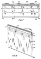
- Figure 1 is a perspective view of the closure end of a prior art self-sealing envelope used for mailing merchandise;
- Figure 2 is a perspective view of the heat-sealing envelope of the present invention showing the envelope closed;
- Figure 3 is a perspective view of the envelope of the present invention showing the envelope open;
- Figure 4 is a front view of the envelope shown in Figure 3;
- Figure 5 is a section view of the envelope taken along the line 5-5 of Figure 4;
- Figure 6 is a perspective view of an alternative embodiment of the envelope of the present invention shown in open condition;
- Figure 7 is a front view of the envelope shown in Figure 6;
- Figure 8 is a perspective view of the envelope shown in Figures 6 and 7 in closed condition;
- Figure 9 is a fragmentary view of still another embodiment of the envelope of the present invention; and
- Figure 10 is a fragmentary view of still another embodiment of the present invention.
- In one conventional type of merchandise mailing envelope, shown in Figure 1, the envelope includes a pair of
panels heat seals 13. The upper end of thepanel 11 extends above the upper edge of thepanel 10 to provide aflap 14. Aband 15 of pressure sensitive adhesive extends across the flap from one side edge to the other. A protective peel-offtape 16 covers the adhesive material. The envelope is made of a sturdy, flexible plastic material. - When the merchandise has been inserted in the envelope and the
protective tape 16 is removed, the upper end of the envelope is folded downwardly above the upper end of the merchandise to enclose the contents compactly within the envelope. The pressure sensitiveadhesive band 15 is pressed against the outer surface of thepanel 10 to seal the envelope. - Referring to Figures 2 to 5, the self-sealing envelope of the present invention includes a pair of
panels fold 22 and joined together along the side edges byheat seals 23. The upper end of thepanel 21 extends above the upper ends of the heat sealed edges to provide ataller flap 24. Aband 25 of pressure sensitive adhesive extends across theflap 24 from one side edge to the other. A protective peel-offtape 26 covers the adhesive material. - The upper end of the
panel 20 extends above the upper ends of the heat sealed edges to provide ashorter flap 27, the upper end of which interfaces with the lower region of the adhesive band when the protective tape is removed. - The envelope is made of a sturdy, flexible plastic material, for example, a combination high density and linear low density film or a coextruded structure or various resins of a guage within the range of about 1.5 to 5 mils. The envelope is capable of withstanding the normal handling to which it will be subjected in use.
- The taller and
shorter flaps protective tape 26 and interfacing the upper end of theflap 27 with the lower region of the adhesive band to provide a continuous seal across the interfacing flaps. The upper end of the envelope is then folded downwardly above the upper end of the merchandise to enclose the contents compactly within the envelope. The upper exposed band of the pressure sensitive adhesive is then pressed against the outer surface of thepanel 20 to seal the envelope across the widths of theflap 24 andpanel 20. - The
flaps ends 28 to provide small air vents below theadhesive band 25 so that the air can be exhausted from the envelope and the envelopes can be stacked or stored in the smallest possible space without entrapped air. - The self-sealing envelope of the present invention embodies a double seal, namely, an initial transverse seal across the entire width of the
flaps flap 24 and the outer surface of thepanel 20. - In a preferred alternative embodiment of the self-sealing envelope of the present invention, shown in Figures 6 to 8, the envelope includes a pair of
panels fold line 32 and joined together along the side edges byheat seals 33. The upper end of thepanel 31 extends above theheat seals 33 to provide ataller flap 34. Aband 35 of pressure sensitive adhesive extends across theflap 34 from one side edge to the other, and a protective peel-offtape 36 covers the adhesive material. - The upper end of the
panel 30 has ashorter flap 37 which is folded back against the outer surface of thepanel 30 and heat sealed at 38 along opposite edges to anchor theflap 37 in folded back position until the merchandise has been inserted and the envelope is ready to be closed. - The
flaps tear lines lines - When the merchandise is placed in the envelope, the
protective tape 26 is removed to expose theadhesive band 35. The heat sealedends 38 retain theshorter flap 37 in folded back position until the envelope is ready to be sealed, so that theshorter flap 37 will not be prematurely adhered to the adhesive before the flaps are ready to be sealed. The heat sealed ends of the lower flap are readily separated from thepanel 30 to permit theflap 37 to be pivoted about its weakenedline 40 to engage the lower region of theadhesive band 35. The upper end of the envelope is then folded downwardly above the upper end of the merchandise to bring the exposed upper region of the adhesive band into engagement with the outer surface of thepanel 30. - The
flaps notches 41 at opposite ends of the weakenedtear lines notches 41 also provide ready access to the weakenedlines - The envelope of the present invention can be made continuously from extruded plastic film by folding the
panel 30 over thepanel 31, forming the weakenedlines panel 37 along the weakenedline 40 and then simultaneously forming theheat seals flap 34 in the form of a precoated tape with a release liner or a pressure sensitive hot melt to which a protective tape with a release coating is applied. - In a modified alternative embodiment of the seal-sealing envelope of the present invention, shown in Fig. 9, the closure of the envelope is defined between a
taller flap 44 and ashorter flap 47. Thetaller flap 44 has aband 45 of pressure sensitive adhesive extending across it from one side edge to the other with a protective peel-offtape 46 covering the adhesive material. Theshorter flap 47 is folded back and sealed at 48 to anchor it in folded back position until the merchandise has been inserted and the envelope is ready to be closed. Theflaps tear lines flap 44 is provided with a tapered cut awayportion 51, which extends from above thetear line 49 to the upper end of theflap 44 so that the unsealed portion adjacent the tapered line below the pressuresensitive adhesive band 45 provides an air vent to the envelope when the envelope is sealed. - In another embodiment of the invention shown in Figure 10, the
taller flap 44 is provided with twodiscrete bands protective tape 46. Theupper band 45b is about 50% wider than thelower band 45a. Theshorter flap 47 adheres to thelower band 45a when theprotective tape 46 is removed and the shorter flap is turned up to make the initial seal of the envelope. The wider adhesive band is used for the final seal when thetaller flap 44 is folded down whatever distance is necessary to make a compact package. - The invention has been shown in preferred forms and by way of example only, and many modifications and variations can be made therein within the spirit of the invention. For example, the panels of the envelope can be connected along the side edges and bottom by gussets to accommodate bulkier merchandise. The invention, therefore, is not intended to be limited to any specified form or embodiment except insofar as such limitations are expressly set forth in the claims.
Claims (13)
Applications Claiming Priority (2)
| Application Number | Priority Date | Filing Date | Title |
|---|---|---|---|
| US88671 | 1987-08-24 | ||
| US07/088,671 US4759643A (en) | 1987-08-24 | 1987-08-24 | Self-sealing envelope |
Publications (2)
| Publication Number | Publication Date |
|---|---|
| EP0304884A1 true EP0304884A1 (en) | 1989-03-01 |
| EP0304884B1 EP0304884B1 (en) | 1992-04-15 |
Family
ID=22212734
Family Applications (1)
| Application Number | Title | Priority Date | Filing Date |
|---|---|---|---|
| EP88113752A Expired - Lifetime EP0304884B1 (en) | 1987-08-24 | 1988-08-24 | Self-sealing envelope |
Country Status (5)
| Country | Link |
|---|---|
| US (1) | US4759643A (en) |
| EP (1) | EP0304884B1 (en) |
| JP (1) | JPS6470359A (en) |
| CA (1) | CA1316879C (en) |
| DE (1) | DE3870098D1 (en) |
Cited By (1)
| Publication number | Priority date | Publication date | Assignee | Title |
|---|---|---|---|---|
| DE10300039A1 (en) * | 2003-01-03 | 2004-07-15 | Anton Debatin GmbH Werk für werbende Verpackung | Plastics film bag has a projecting lower layer, to form a closure flap, with an adhesive between the flap and a hinged cover which does not affect the work of packers or packaging machines |
Families Citing this family (51)
| Publication number | Priority date | Publication date | Assignee | Title |
|---|---|---|---|---|
| US4961503A (en) * | 1988-03-17 | 1990-10-09 | Kapak Corporation | Tamper evident notched sealing envelope |
| US5046621A (en) * | 1988-03-17 | 1991-09-10 | Kapak Corporation | Tamper evident notched sealing envelope |
| US4932791A (en) * | 1988-04-28 | 1990-06-12 | Uniflex, Inc. | Envelope closure seal and method |
| JPH0618899Y2 (en) * | 1988-09-29 | 1994-05-18 | 株式会社細川洋行 | Retort packaging bag for food |
| US4941196A (en) * | 1988-11-01 | 1990-07-10 | Kcl Corporation | Tamper evident bag |
| US5014852A (en) * | 1988-12-30 | 1991-05-14 | Mobil Oil Corp. | Pad of bags |
| US5041072A (en) * | 1989-10-13 | 1991-08-20 | Cyril-Scott Company | Method of making flapped envelope with peel-off strip for band of pressure-sensitive adhesive |
| US5205649A (en) * | 1990-08-29 | 1993-04-27 | Trigon Packaging Corporation | Leakproof packaging |
| US5174659A (en) * | 1991-06-21 | 1992-12-29 | Vonco Products, Inc. | Reclosable flexible bag |
| US5639523A (en) * | 1995-01-20 | 1997-06-17 | Ellis; Dana R. | Decorative sheet material |
| US5520449A (en) * | 1995-03-24 | 1996-05-28 | Klak; Joseph V. | Asbestos glove bag |
| US5549388A (en) * | 1995-05-22 | 1996-08-27 | Wilkes; Kenneth R. | Pleated sterilization pouch |
| US6048098A (en) * | 1995-06-06 | 2000-04-11 | Uniflex, Inc. | Tamper-resistant envelope |
| US5620256A (en) * | 1995-08-22 | 1997-04-15 | Makrauer; George A. | Tamper evident security bag |
| US5918983A (en) * | 1996-11-08 | 1999-07-06 | Control Paper Co., Inc. | Security envelope |
| US6012844A (en) * | 1999-02-16 | 2000-01-11 | Huseman; David C. | Selectively closeable plastic film bag |
| US6318893B1 (en) * | 2000-05-02 | 2001-11-20 | Gates Automation, Inc. | Bag for automated filing and sealing machine |
| US20020011304A1 (en) | 2000-05-03 | 2002-01-31 | Elijah Abron | Substrate sheets with removable strip |
| US7419301B2 (en) * | 2001-08-31 | 2008-09-02 | Illinois Tool Works Inc. | Tamper-evident easy-open slider package and related methods of manufacture |
| US6575627B2 (en) * | 2001-10-09 | 2003-06-10 | David C. Huseman | Selectively closeable plastic film bag structure |
| US20030127952A1 (en) * | 2001-11-13 | 2003-07-10 | Miguel Friedenbach | Assembly for the physical manipulation of potentially contaminated articles |
| CN1612829A (en) * | 2002-01-11 | 2005-05-04 | 埃尔萨塞包装股份公司 | Resealable packaging bag |
| US6953148B2 (en) * | 2002-05-31 | 2005-10-11 | Sealed Air Corporation | Mail collection bag |
| US6913388B2 (en) * | 2002-06-07 | 2005-07-05 | Vonco Products, Inc. | Flexible container |
| US7004632B2 (en) | 2003-03-31 | 2006-02-28 | The Glad Products Company | Ventable storage bag |
| JP2006526551A (en) | 2003-06-03 | 2006-11-24 | プライアント・コーポレイション | Disposable container |
| DE202004012986U1 (en) * | 2004-08-19 | 2004-10-14 | Anton Debatin GmbH Werk für werbende Verpackung | security bag |
| US20060204148A1 (en) * | 2005-03-01 | 2006-09-14 | Broadway Kleer-Guard Corp. | Plastic bag designed for dispensing |
| US20080310772A1 (en) * | 2006-05-01 | 2008-12-18 | Dayton Douglas C | Systems and methods for waste disposal using a disposal bag with a rectangular frame |
| US20080247679A1 (en) * | 2006-05-01 | 2008-10-09 | Dayton Douglas C | Systems and methods for waste disposal using a wearable disposal bag |
| GB0621240D0 (en) * | 2006-10-25 | 2006-12-06 | Encore Washington Ltd | Envelope and corresponding method of production |
| FR2908745B1 (en) * | 2006-11-16 | 2009-02-06 | Alpem Soc Par Actions Simplifi | PREFORMED PACKAGING BAG, IN PARTICULAR FOR FOOD PRODUCTS. |
| US8157443B2 (en) * | 2008-09-19 | 2012-04-17 | Khan Dayna N | Radiograph cassette cover |
| US20110038569A1 (en) * | 2009-08-13 | 2011-02-17 | Scott Huffer | Easy-open resealable package |
| USD667228S1 (en) | 2009-09-24 | 2012-09-18 | Yuyama Manufacturing Co., Ltd. | Sheet for a drug bag |
| WO2012054982A1 (en) * | 2010-10-27 | 2012-05-03 | Macgregor Manufacturing Investments Pty Limited | Envelopes and methods for their production |
| US8905638B2 (en) | 2011-02-16 | 2014-12-09 | Cryovac, Inc. | Easy open and reclosable package with die-cut web, and discrete strip anchored to second side panel |
| US8800250B2 (en) | 2011-02-16 | 2014-08-12 | Cryovac, Inc. | Easy open and reclosable package with discrete laminate, with die-cut, anchored to second side panel |
| US9211976B2 (en) | 2011-02-16 | 2015-12-15 | Andrew W. Moehlenbrock | Easy open and reclosable package with discrete laminate, with die-cut, anchored to second side panel |
| US20150225126A1 (en) * | 2014-02-13 | 2015-08-13 | Gary L. Sharpe | Tamper evident unit dose packaging |
| US20160090217A1 (en) * | 2014-09-29 | 2016-03-31 | Donald C. Schnabel | Pouch with peelable seal for beverages |
| DK3015394T3 (en) * | 2014-10-31 | 2018-01-29 | Papier-Mettler Kg | Shipping Bag |
| EP3015393A1 (en) * | 2014-10-31 | 2016-05-04 | Papier-Mettler KG | Mailer bag |
| JP5913699B1 (en) * | 2015-07-24 | 2016-04-27 | トタニ技研工業株式会社 | Plastic bag and bag making machine |
| US10053263B2 (en) * | 2015-08-21 | 2018-08-21 | Inteplast Group Corporation | Tearable container closure and envelope comprising same |
| USD840835S1 (en) | 2016-12-09 | 2019-02-19 | Pan Pacific Plastics Mfg., Inc. | Sealable wave bag |
| US10464718B2 (en) * | 2016-12-09 | 2019-11-05 | Pan Pacific Plastics Mfg., Inc. | Sealable wave bag assembly with integrated venting |
| US20180162603A1 (en) * | 2016-12-09 | 2018-06-14 | Pan Pacific Plastics Mfg., Inc. | Sealable plastic bag assembly |
| WO2019126446A1 (en) * | 2017-12-20 | 2019-06-27 | Sev-Rend Corporation | Sealable container |
| WO2023034806A1 (en) * | 2021-09-02 | 2023-03-09 | Pac Worldwide Corporation | Release liner for mailer packages |
| US20230233165A1 (en) * | 2022-01-25 | 2023-07-27 | Kurt Hainze | Portable x-ray cassette positioning system and method |
Citations (2)
| Publication number | Priority date | Publication date | Assignee | Title |
|---|---|---|---|---|
| US2154780A (en) * | 1938-10-21 | 1939-04-18 | Silverberg Isadore Monte | Combined envelope and savings bank |
| FR1240075A (en) * | 1959-07-23 | 1960-09-02 | Improvement in the closing of plastic film bags |
Family Cites Families (6)
| Publication number | Priority date | Publication date | Assignee | Title |
|---|---|---|---|---|
| US3310225A (en) * | 1965-08-06 | 1967-03-21 | Dow Chemical Co | Resealable container closure from self-adherent chlorinated olefin polymer films |
| US4276982A (en) * | 1977-10-26 | 1981-07-07 | Arvey Corporation | Pressure sensitive tape closure pouch |
| US4483018A (en) * | 1981-02-09 | 1984-11-13 | Impakt Products, Inc. | High integrity tamper resistant container |
| US4464158A (en) * | 1982-04-27 | 1984-08-07 | Kardon Donald R | Method of making tamperproof bag closure |
| GB8308303D0 (en) * | 1983-03-25 | 1983-05-05 | Smiths Bros Whitehaven Ltd | Pouches |
| US4690322A (en) * | 1986-10-31 | 1987-09-01 | Burns Joseph E | Resealable envelope |
-
1987
- 1987-08-24 US US07/088,671 patent/US4759643A/en not_active Expired - Lifetime
-
1988
- 1988-08-17 CA CA000574964A patent/CA1316879C/en not_active Expired - Fee Related
- 1988-08-24 EP EP88113752A patent/EP0304884B1/en not_active Expired - Lifetime
- 1988-08-24 DE DE8888113752T patent/DE3870098D1/en not_active Expired - Fee Related
- 1988-08-24 JP JP63210415A patent/JPS6470359A/en active Pending
Patent Citations (2)
| Publication number | Priority date | Publication date | Assignee | Title |
|---|---|---|---|---|
| US2154780A (en) * | 1938-10-21 | 1939-04-18 | Silverberg Isadore Monte | Combined envelope and savings bank |
| FR1240075A (en) * | 1959-07-23 | 1960-09-02 | Improvement in the closing of plastic film bags |
Cited By (1)
| Publication number | Priority date | Publication date | Assignee | Title |
|---|---|---|---|---|
| DE10300039A1 (en) * | 2003-01-03 | 2004-07-15 | Anton Debatin GmbH Werk für werbende Verpackung | Plastics film bag has a projecting lower layer, to form a closure flap, with an adhesive between the flap and a hinged cover which does not affect the work of packers or packaging machines |
Also Published As
| Publication number | Publication date |
|---|---|
| JPS6470359A (en) | 1989-03-15 |
| CA1316879C (en) | 1993-04-27 |
| EP0304884B1 (en) | 1992-04-15 |
| US4759643A (en) | 1988-07-26 |
| DE3870098D1 (en) | 1992-05-21 |
Similar Documents
| Publication | Publication Date | Title |
|---|---|---|
| CA1316879C (en) | Self-sealing envelope | |
| US5174659A (en) | Reclosable flexible bag | |
| US5167455A (en) | Container | |
| US3990627A (en) | Z-Fold adhesive stripe closure for bags | |
| US7300207B2 (en) | Closure for containers and reclosable containers including the same | |
| US4953708A (en) | Flexible package with pour spout and handle | |
| US5044772A (en) | Flexible bag with supporting and sealing tape | |
| US3507444A (en) | Packing list envelope | |
| US5307988A (en) | Soft pack for paper tissues | |
| US5346301A (en) | Reclosable bag with offset end seal | |
| US20060131201A1 (en) | Packaging body | |
| US20040208399A1 (en) | Closure for containers and reclosable containers including the same | |
| US4550441A (en) | Vented bag | |
| US4103821A (en) | Shipping envelope | |
| US3076541A (en) | Envelope type package with cover and removable disclosure sheet | |
| US4832507A (en) | Thermoplastic draw tape bag held closed by microencapsulated adhesive | |
| US5045040A (en) | Envelope closure seal and method | |
| US3784087A (en) | Tamperproof, recloseable package and closure therefor | |
| US6702460B1 (en) | High strength plastic bag | |
| CA2185959C (en) | Reclosable packaging | |
| EP0827912A2 (en) | Resealable package | |
| US4117934A (en) | Reclosable bag | |
| US3380576A (en) | Tobacco pouches | |
| US5251755A (en) | Package having a leader secured over a pouch | |
| US4836382A (en) | Photo print envelope containing coupon pouch |
Legal Events
| Date | Code | Title | Description |
|---|---|---|---|
| PUAI | Public reference made under article 153(3) epc to a published international application that has entered the european phase |
Free format text: ORIGINAL CODE: 0009012 |
|
| AK | Designated contracting states |
Kind code of ref document: A1 Designated state(s): BE DE FR GB IT NL |
|
| 17P | Request for examination filed |
Effective date: 19890414 |
|
| 17Q | First examination report despatched |
Effective date: 19901210 |
|
| GRAA | (expected) grant |
Free format text: ORIGINAL CODE: 0009210 |
|
| AK | Designated contracting states |
Kind code of ref document: B1 Designated state(s): BE DE FR GB IT NL |
|
| REF | Corresponds to: |
Ref document number: 3870098 Country of ref document: DE Date of ref document: 19920521 |
|
| ITF | It: translation for a ep patent filed |
Owner name: GUZZI E RAVIZZA S.R.L. |
|
| ET | Fr: translation filed | ||
| PLBE | No opposition filed within time limit |
Free format text: ORIGINAL CODE: 0009261 |
|
| STAA | Information on the status of an ep patent application or granted ep patent |
Free format text: STATUS: NO OPPOSITION FILED WITHIN TIME LIMIT |
|
| 26N | No opposition filed | ||
| PGFP | Annual fee paid to national office [announced via postgrant information from national office to epo] |
Ref country code: FR Payment date: 19960814 Year of fee payment: 9 |
|
| PGFP | Annual fee paid to national office [announced via postgrant information from national office to epo] |
Ref country code: NL Payment date: 19960820 Year of fee payment: 9 Ref country code: DE Payment date: 19960820 Year of fee payment: 9 |
|
| PGFP | Annual fee paid to national office [announced via postgrant information from national office to epo] |
Ref country code: BE Payment date: 19960827 Year of fee payment: 9 |
|
| PGFP | Annual fee paid to national office [announced via postgrant information from national office to epo] |
Ref country code: GB Payment date: 19960828 Year of fee payment: 9 |
|
| PG25 | Lapsed in a contracting state [announced via postgrant information from national office to epo] |
Ref country code: GB Free format text: LAPSE BECAUSE OF NON-PAYMENT OF DUE FEES Effective date: 19970824 |
|
| PG25 | Lapsed in a contracting state [announced via postgrant information from national office to epo] |
Ref country code: BE Free format text: LAPSE BECAUSE OF NON-PAYMENT OF DUE FEES Effective date: 19970831 |
|
| BERE | Be: lapsed |
Owner name: EQUITABLE BAG CO. INC. Effective date: 19970831 |
|
| PG25 | Lapsed in a contracting state [announced via postgrant information from national office to epo] |
Ref country code: NL Free format text: LAPSE BECAUSE OF NON-PAYMENT OF DUE FEES Effective date: 19980301 |
|
| GBPC | Gb: european patent ceased through non-payment of renewal fee |
Effective date: 19970824 |
|
| PG25 | Lapsed in a contracting state [announced via postgrant information from national office to epo] |
Ref country code: FR Free format text: LAPSE BECAUSE OF NON-PAYMENT OF DUE FEES Effective date: 19980430 |
|
| PG25 | Lapsed in a contracting state [announced via postgrant information from national office to epo] |
Ref country code: DE Free format text: LAPSE BECAUSE OF NON-PAYMENT OF DUE FEES Effective date: 19980501 |
|
| NLV4 | Nl: lapsed or anulled due to non-payment of the annual fee |
Effective date: 19980301 |
|
| REG | Reference to a national code |
Ref country code: FR Ref legal event code: ST |
|
| PG25 | Lapsed in a contracting state [announced via postgrant information from national office to epo] |
Ref country code: IT Free format text: LAPSE BECAUSE OF NON-PAYMENT OF DUE FEES Effective date: 20050824 |