EP0303978A2 - Method and circuit for enhancing the resolution of digital signals - Google Patents
Method and circuit for enhancing the resolution of digital signals Download PDFInfo
- Publication number
- EP0303978A2 EP0303978A2 EP88113105A EP88113105A EP0303978A2 EP 0303978 A2 EP0303978 A2 EP 0303978A2 EP 88113105 A EP88113105 A EP 88113105A EP 88113105 A EP88113105 A EP 88113105A EP 0303978 A2 EP0303978 A2 EP 0303978A2
- Authority
- EP
- European Patent Office
- Prior art keywords
- circuit
- digits
- coefficients
- transformation
- data words
- Prior art date
- Legal status (The legal status is an assumption and is not a legal conclusion. Google has not performed a legal analysis and makes no representation as to the accuracy of the status listed.)
- Granted
Links
Images


Classifications
-
- H—ELECTRICITY
- H01—ELECTRIC ELEMENTS
- H01F—MAGNETS; INDUCTANCES; TRANSFORMERS; SELECTION OF MATERIALS FOR THEIR MAGNETIC PROPERTIES
- H01F38/00—Adaptations of transformers or inductances for specific applications or functions
- H01F38/42—Flyback transformers
-
- H—ELECTRICITY
- H04—ELECTRIC COMMUNICATION TECHNIQUE
- H04N—PICTORIAL COMMUNICATION, e.g. TELEVISION
- H04N19/00—Methods or arrangements for coding, decoding, compressing or decompressing digital video signals
- H04N19/60—Methods or arrangements for coding, decoding, compressing or decompressing digital video signals using transform coding
Definitions
- the invention relates to a method for improving the resolution of digital signals according to the preamble of patent claim 1.
- a two-dimensional integer division of the coefficient blocks is carried out, for example, in the case of a two-dimensional transformation of the block size 8 * 8 eight and thus rounding the transformation values. It has been shown that with small alternating parts of the transformed coefficients, ie with soft structures in the original image, coarser structures occur after the back transformation. This is due to the fact that the rounding of the transformed values means that information is lost which is missing during the back transformation and which is disruptively visible due to the lack of masking by higher-frequency signal components.
- the object of the invention is to obtain a better reproduction of smaller signal changes in the original area after the back-transformation by limiting the number of digits in the frequency range.
- the values of large coefficients are unchanged, i.e. e.g. transmitted twice divided by eight and the values of small coefficients, which are still important for the image impression, i.e. are not set to zero, are transmitted with greater accuracy.
- This is done by making better use of the number of digits available by not dividing the values of small coefficients twice by eight in the same way as the values of large coefficients, but rather by a smaller number and thus increasing them relatively.
- at least one additional position is occupied by the positions available during the transmission. This magnification is then taken into account in the reverse transformation.
- the invention further relates to a circuit arrangement for improving the resolution of television signals according to the preamble of claim 4.
- the task is to create a circuit arrangement which, if the number of digits corresponds between the values in the original area and those in the frequency area, enables better reproduction of small signal changes in the original area after the back transformation.
- This object is achieved in a circuit arrangement according to the preamble of claim 4 by the features specified in the characterizing part.
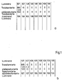
- luminance values of the first eight pixels of an 8 ⁇ 8 matrix into which a television picture is broken down are plotted.
- the luminance values gradually increase from left to right. In the original area, this is recognizable as a so-called gray wedge.
- the values given in the second line result, the first coefficient representing the DC component and the following coefficients representing the AC components.
- the second coefficient disappears, so that after reverse transformation tion, only a constant luminance value is calculated. This is indicated on the fourth line. If the gray wedge continues over the blocks to the right, stair structures become visible in the reproduced image.
- Fig. 1b the coefficients of the alternating components are increased, so that the second coefficient does not become zero despite rounding to a smaller number of digits.
- the reverse transformation shows that different luminance values can now be displayed that come much closer to the original. If only the small coefficients are enlarged and the large coefficients are retained, the image resolution can be increased without the total number of digits of the data words to be transmitted and thus the amount of data having to be increased.
- Fig. 2 shows a circuit arrangement for different quantization of the coefficients.
- the transformed values of the luminance signals for example blocks with 8 x 8 or 2 x 4 x 8 pixels, reach a memory circuit 1 as nine-digit binary data words with an additional sign bit. All the sixty-four coefficients occurring with the block size are stored there.
- the maximum value of the coefficients containing alternating components is now determined from the coefficients in a maximum value detection circuit 2, which can be designed, for example, as a counter. After buffering, this value then arrives at address inputs 3 of a memory 4 serving as a division circuit and forms a divisor for the relative enlargement of small coefficients.
- the magnification factor compared to the standard divisor of sixty-four can be between sixty-two and sixty-four depending on the maximum alternating component serving as a reference value and the size of the other coefficients.
- the quantization carried out in the circuit according to FIG. 2 is undone again.
- the circuit shown in FIG. 3 serves this purpose, which corresponds in principle to that in FIG. 2, but in which the multiplication table in the memory 4 contains the reciprocal values of those from the memory 4 in FIG. 1.
- the number of digits of the data words is increased again.
- the eight-digit data words again result in data words with nine digits plus sign bit, which in the subsequent reverse transformation from the frequency range to the original range lead to the desired better reproduction of the television signals.
Abstract
Description
Die Erfindung betrifft ein Verfahren zur Verbesserung der Auflösung von digitalen Signalen nach dem Oberbegriff des Patentanspruchs 1.The invention relates to a method for improving the resolution of digital signals according to the preamble of patent claim 1.
Um bei der digitialen Übertragung von Fernseh-Signalen den Datenumfang zu reduzieren, ist es bekannt, die Fernseh-Signale vom Originalbereich blockweise zunächst in einen Frequenzbereich zu transformieren, von den aufgrund der Transformation erhaltenen Spektralkoeffizienten nur die wesentlichen Koeffizienten zu übertragen und die unwesentlichen zu Null zu setzen und anschließend die transformierten Werte wieder in den Originalbereich zurückzutransformieren. Die Transformation erfolgt durch Multiplikation der Signalwerte mit einer Transformationsfunktion, wobei die Stellenzahl infolge der Transformation zunimmt. Um die Stellenzahl auf den für eine ausreichende Auflösung der Abstufungen der Luminanz- und/oder Chrominanz-Signalwerte festgelegten Wert, z.B. 8 Bit plus Vorzeichen zu reduzieren, wird z.B. bei einer zweidimensionalen Transformation der Blockgröße 8*8 eine zweidimensionale Integer-Division der Koeffizientenblöcke durch acht und damit eine Rundung der Transformationswerte vorgenommen. Es hat sich gezeigt, daß bei kleinen Wechselanteilen der transformierten Koeffizienten, d.h. bei sanften Strukturen im Originalbild, gröbere Strukturen nach der Rücktransformation auftreten. Dies liegt daran, daß durch die Rundung der transformierten Werte Informationen verlorengehen, die bei der Rücktransformation fehlen und aufgrund nicht vorhandenen Maskierung durch höherfrequente Signalanteile störend sichtbar werden.In order to reduce the data volume in the digital transmission of television signals, it is known to first transform the television signals from the original area block by block into a frequency range, to transmit only the essential coefficients from the spectral coefficients obtained as a result of the transformation, and the insignificant ones to zero and then transform the transformed values back into the original area. The transformation is carried out by multiplying the signal values by a transformation function, the number of digits increasing as a result of the transformation. In order to reduce the number of digits to the value specified for sufficient resolution of the gradations of the luminance and / or chrominance signal values, for example 8 bits plus sign, a two-dimensional integer division of the coefficient blocks is carried out, for example, in the case of a two-dimensional transformation of the
Der Erfindung liegt die Aufgabe zugrunde, bei Begrenzung der Stellenzahl im Frequenzbereich eine bessere Reproduktion kleinerer Signalveränderungen im Originalbereich nach der Rücktransformation zu erhalten.The object of the invention is to obtain a better reproduction of smaller signal changes in the original area after the back-transformation by limiting the number of digits in the frequency range.
Diese Aufgabe wird bei einem Verfahren nach dem Oberbegriff des Anspruchs 1 durch die im kennzeichnenden Teil angegebenen Merkmale gelöst.This object is achieved in a method according to the preamble of claim 1 by the features specified in the characterizing part.
Bei der Erfindung werden die Werte großer Koeffizienten unverändert, d.h. z.B. zweimal durch acht geteilt übertragen und die Werte kleiner Koeffzienten, die noch für den Bildeindruck wesentlich sind, also nicht zu Null gesetzt werden, mit einer höheren Genauigkeit übertragen. Dies geschieht dadurch, daß die zur Verfügung stehende Stellenzahl besser ausgenutzt wird, indem die Werte kleiner Koeffizienten nicht in gleicher Weise wie die Werte großer Koeffizienten zweimal durch acht sondern durch eine kleinere Zahl geteilt und damit relativ vergrößert werden. Somit wird von den bei der Übertragung zur Verfügung stehenden Stellen wenigstens eine weitere Stelle belegt. Diese Vergrößerung wird anschließend bei der Rücktransformation berücksichtigt.In the invention, the values of large coefficients are unchanged, i.e. e.g. transmitted twice divided by eight and the values of small coefficients, which are still important for the image impression, i.e. are not set to zero, are transmitted with greater accuracy. This is done by making better use of the number of digits available by not dividing the values of small coefficients twice by eight in the same way as the values of large coefficients, but rather by a smaller number and thus increasing them relatively. Thus, at least one additional position is occupied by the positions available during the transmission. This magnification is then taken into account in the reverse transformation.
Die Erfindung betrifft ferner eine Schaltungsanordnung zur Verbesserung der Auflösung von Fernseh-Signalen nach dem Oberbegriff des Anspruchs 4.The invention further relates to a circuit arrangement for improving the resolution of television signals according to the preamble of claim 4.
Diesbezüglich liegt die Aufgabe zugrunde, eine Schaltungsanordnung zu schaffen, welche bei Übereinstimmung der Stellenzahl zwischen den Werten im Originalbereich und denjenigen im Frequenzbereich eine bessere Reproduktion kleiner Signalveränderungen im Originalbereich nach der Rücktransformation ermöglicht. Diese Aufgabe wird bei einer Schaltungsanordnung nach dem Oberbegriff des Anspruchs 4 durch die im Kennzeichen angegebenen Merkmale gelöst.In this regard, the task is to create a circuit arrangement which, if the number of digits corresponds between the values in the original area and those in the frequency area, enables better reproduction of small signal changes in the original area after the back transformation. This object is achieved in a circuit arrangement according to the preamble of claim 4 by the features specified in the characterizing part.
Weiterbildungen und vorteilhafte Ausführungsformen der Erfindung ergeben sich aus den weiteren Ansprüchen, der Beschreibung und der Zeichnung, anhand der ein Ausführungsbeispiel der Erfindung nachfolgend erläutert wird.Further developments and advantageous embodiments of the invention result from the further claims, the description and the drawing, on the basis of which an embodiment of the invention is explained below.
In der Zeichnung zeigen:
- Fig 1a eine Tabelle von Luminanz-Signalwerten, die transformiert, gerundet und rücktransformiert sind ohne die erfindungsgemäßen Maßnahmen;
- Fig 1b die gleichen Basiswerte wie in Fig. 1a, jedoch nach Durchführung der erfindungsgemäßen Maßnahmen;
- Fig. 2 eine Schaltungsanordnung zur Durchführung einer Quantisierung nach der Transformation und
- Fig 3 eine Schaltungsanordnung zu Dequantisierung vor der Rücktransformation.
- 1a shows a table of luminance signal values which are transformed, rounded and back-transformed without the measures according to the invention;
- 1b shows the same basic values as in FIG. 1a, but after the measures according to the invention have been carried out;
- Fig. 2 shows a circuit arrangement for performing a quantization after the transformation and
- 3 shows a circuit arrangement for dequantization before the back transformation.
In der in Fig. 1 dargestellten Tabelle sind Luminanzwerte der ersten acht Pixel einer 8 x 8 Matrix, in die ein Fernsehbild zerlegt ist, aufgetragen. Die Luminanzwerte wachsen allmählich von links nach rechts an. Im Originalbereich ist dies als sog. Graukeil erkennbar. Bei Transformation mittels Diskreter-Cosinus-Transformation ergeben sich die in der zweiten Zeile angegebenen Werte, wobei der erste Koeffizient den Gleichanteil und die folgenden Koeffizienten die Wechselanteile darstellen. Nach Rundung, in diesem Falle nach Division durch 8, angegeben in der dritten Zeile in Fig. 1a, verschwindet der zweite Koeffizient, sodaß nach Rücktransforma tion nur ein konstanter Luminanzwert errechnet wird. Dieser ist in der vierten Zeile angegeben. Setzt sich der Graukeil über die sich rechts anschließenden Blöcke fort, so werden im reproduzierten Bild Treppenstrukturen sichtbar.In the table shown in FIG. 1, luminance values of the first eight pixels of an 8 × 8 matrix into which a television picture is broken down are plotted. The luminance values gradually increase from left to right. In the original area, this is recognizable as a so-called gray wedge. In the case of transformation by means of a discrete-cosine transformation, the values given in the second line result, the first coefficient representing the DC component and the following coefficients representing the AC components. After rounding, in this case after division by 8, indicated in the third line in FIG. 1a, the second coefficient disappears, so that after reverse transformation tion, only a constant luminance value is calculated. This is indicated on the fourth line. If the gray wedge continues over the blocks to the right, stair structures become visible in the reproduced image.
In Fig. 1b sind die Koeffizienten der Wechselanteile vergrößert, sodaß der zweite Koeffizient trotz Rundung auf eine kleinere Stellenzahl nicht zu Null wird. Die Rücktransformation zeigt, daß nunmehr unterschiedliche Luminanzwerte darstellbar sind, die dem Original wesentlich näher kommen. Werden nur die kleinen Koeffizienten vergrößert und die großen Koeffizienten beibehalten, so kann die Bildauflösung gesteigert werden, ohne daß die insgesamt zu übertragende Stellenzahl der Datenworte und damit die Datenmenge erhöht werden muß.In Fig. 1b, the coefficients of the alternating components are increased, so that the second coefficient does not become zero despite rounding to a smaller number of digits. The reverse transformation shows that different luminance values can now be displayed that come much closer to the original. If only the small coefficients are enlarged and the large coefficients are retained, the image resolution can be increased without the total number of digits of the data words to be transmitted and thus the amount of data having to be increased.
Fig. 2 zeigt eine Schaltungsanordnung zur unterschiedlichen Quantisierung der Koeffizienten. Die transformierten Werte der Luminanzsignale, z.B. Blöcke mit 8 x 8 oder 2 x 4 x 8 Pixels, gelangen als neunstellige Binär-Datenworte mit einem zusätzlichen Vorzeichenbit zu einer Speicherschaltung 1. Dort werden alle bei der Blockgröße auftretenden vierundsechzig Koeffizienten gespeichert. Von den Koeffizienten wird nun in einer Maximalwert-Erkennungsschaltung 2, die z.B. als Zähler ausgebildet sein kann, der Maximalwert der Wechselanteile beinhaltenden Koeffizienten ermittelt. Dieser Wert gelangt dann nach Zwischenspeicherung zu Adresseingängen 3 eines als Divisionsschaltung dienenden Speichers 4 und bildet einen Divisor für die relative Vergrößerung kleiner Koeffizienten. Danach gelangen unter Zeitverzögerung alle Koeffizienten des Blockes, dessen Maximalwert zuvor ermittelt wurde, als neunstellige Binär-Worte plus Vorzeichenbit an die Adresseingänge 5 des Speichers 4. Wahrend die den Gleichanteil und den maximalen Wechselanteil enthaltenden Koeffizienten unverändert gelassen werden, wird anhand einer im Spei cher 4 gespeicherten Divisionstabelle eine relative Vergrößerung der übrigen Koeffizienten vorgenommen. Der Vergrößerungsfaktor gegenüber dem Standarddivisor von vierundsechzig kann dabei in Abhängigkeit des als Bezugswert dienenden maximalen Wechselanteils und der Größe der übrigen Koeffizienten zwischen zwei und vierundsechzig betragen.Fig. 2 shows a circuit arrangement for different quantization of the coefficients. The transformed values of the luminance signals, for example blocks with 8 x 8 or 2 x 4 x 8 pixels, reach a memory circuit 1 as nine-digit binary data words with an additional sign bit. All the sixty-four coefficients occurring with the block size are stored there. The maximum value of the coefficients containing alternating components is now determined from the coefficients in a maximum
Am Ausgang 6 des Speichers 4 sind die achtstelligen Datenworte plus Vorzeichenbit abgreifbar, bei welchen die Koeffizienten mit geringen Wechselanteilen mit einer höheren Auflösung quantisiert, das heißt vergrößert enthalten sind. Die erwähnte Zwischenspeicherung und Zeitverzögerung wird in dafür vorgesehenen Zwischenspeichern 7 und Verzögerungsschaltungen 8 vorgenommen.At the
Vor der Rücktransformation wird der in der Schaltung nach Fig. 2 durchgeführte Quantisierung wieder rückgängig gemacht. Dazu dient die in Fig. 3 dargestellte Schaltung, welche im Prinzip derjenigen in Fig. 2 entspricht, bei der jedoch die Multiplikationstabelle im Speicher 4 die reziproken Werte derjenigen aus dem Speicher 4 in Fig. 1 enthält. Dabei wird auch wieder die Stellenzahl der Datenworte erhöht. So-mit entstehen aus den achtstelligen Datenworten wieder Datenworte mit neun Stellen plus Vorzeichenbit, die bei der folgenden Rücktransformation aus dem Frequenzbereich in den Originalbereich zu der angestrebten besseren Reproduktion der Fernseh-Signale führen.Before the back transformation, the quantization carried out in the circuit according to FIG. 2 is undone again. The circuit shown in FIG. 3 serves this purpose, which corresponds in principle to that in FIG. 2, but in which the multiplication table in the memory 4 contains the reciprocal values of those from the memory 4 in FIG. 1. The number of digits of the data words is increased again. Thus, the eight-digit data words again result in data words with nine digits plus sign bit, which in the subsequent reverse transformation from the frequency range to the original range lead to the desired better reproduction of the television signals.
Claims (6)
Applications Claiming Priority (2)
| Application Number | Priority Date | Filing Date | Title |
|---|---|---|---|
| DE3727874 | 1987-08-21 | ||
| DE19873727874 DE3727874A1 (en) | 1987-08-21 | 1987-08-21 | METHOD AND CIRCUIT FOR IMPROVING THE RESOLUTION OF DIGITAL SIGNALS |
Publications (3)
| Publication Number | Publication Date |
|---|---|
| EP0303978A2 true EP0303978A2 (en) | 1989-02-22 |
| EP0303978A3 EP0303978A3 (en) | 1991-01-30 |
| EP0303978B1 EP0303978B1 (en) | 1994-11-30 |
Family
ID=6334168
Family Applications (1)
| Application Number | Title | Priority Date | Filing Date |
|---|---|---|---|
| EP88113105A Expired - Lifetime EP0303978B1 (en) | 1987-08-21 | 1988-08-12 | Method and circuit for enhancing the resolution of digital signals |
Country Status (9)
| Country | Link |
|---|---|
| US (1) | US4887157A (en) |
| EP (1) | EP0303978B1 (en) |
| JP (1) | JP2806944B2 (en) |
| KR (1) | KR890004572A (en) |
| AT (1) | ATE114919T1 (en) |
| CA (1) | CA1330121C (en) |
| DE (2) | DE3727874A1 (en) |
| ES (1) | ES2064334T3 (en) |
| FI (1) | FI88769C (en) |
Families Citing this family (5)
| Publication number | Priority date | Publication date | Assignee | Title |
|---|---|---|---|---|
| DE3914267A1 (en) * | 1989-04-29 | 1990-10-31 | Thomson Brandt Gmbh | SIGNAL PROCESSING SYSTEM FOR DIGITAL SIGNALS |
| US5351087A (en) * | 1990-06-01 | 1994-09-27 | Thomson Consumer Electronics, Inc. | Two stage interpolation system |
| US5374963A (en) * | 1990-06-01 | 1994-12-20 | Thomson Consumer Electronics, Inc. | Picture resolution enhancement with dithering and dedithering |
| US5385475A (en) * | 1993-04-01 | 1995-01-31 | Rauland-Borg | Apparatus and method for generating and presenting an audio visual lesson plan |
| JP4927001B2 (en) * | 2008-02-21 | 2012-05-09 | アイシン・エーアイ株式会社 | Transmission synchromesh mechanism |
Citations (3)
| Publication number | Priority date | Publication date | Assignee | Title |
|---|---|---|---|---|
| US4189748A (en) * | 1977-08-23 | 1980-02-19 | Northrop Corporation | Video bandwidth reduction system using a two-dimensional transformation, and an adaptive filter with error correction |
| US4394774A (en) * | 1978-12-15 | 1983-07-19 | Compression Labs, Inc. | Digital video compression system and methods utilizing scene adaptive coding with rate buffer feedback |
| GB2125255A (en) * | 1982-07-28 | 1984-02-29 | British Broadcasting Corp | Digital data coding |
Family Cites Families (3)
| Publication number | Priority date | Publication date | Assignee | Title |
|---|---|---|---|---|
| JPS6264562A (en) * | 1985-09-18 | 1987-03-23 | Fujitsu Ltd | Pattern conversion device |
| JP2811175B2 (en) * | 1986-01-27 | 1998-10-15 | 富士写真フイルム株式会社 | Orthogonal transform coding method for image data |
| US4704628A (en) * | 1986-07-16 | 1987-11-03 | Compression Labs, Inc. | Combined intraframe and interframe transform coding system |
-
1987
- 1987-08-21 DE DE19873727874 patent/DE3727874A1/en not_active Withdrawn
-
1988
- 1988-08-12 ES ES88113105T patent/ES2064334T3/en not_active Expired - Lifetime
- 1988-08-12 AT AT88113105T patent/ATE114919T1/en not_active IP Right Cessation
- 1988-08-12 DE DE3852241T patent/DE3852241D1/en not_active Expired - Fee Related
- 1988-08-12 EP EP88113105A patent/EP0303978B1/en not_active Expired - Lifetime
- 1988-08-15 US US07/232,221 patent/US4887157A/en not_active Expired - Lifetime
- 1988-08-19 JP JP63204881A patent/JP2806944B2/en not_active Expired - Lifetime
- 1988-08-19 FI FI883857A patent/FI88769C/en not_active IP Right Cessation
- 1988-08-20 KR KR1019880010623A patent/KR890004572A/en not_active Application Discontinuation
- 1988-08-22 CA CA000575383A patent/CA1330121C/en not_active Expired - Fee Related
Patent Citations (3)
| Publication number | Priority date | Publication date | Assignee | Title |
|---|---|---|---|---|
| US4189748A (en) * | 1977-08-23 | 1980-02-19 | Northrop Corporation | Video bandwidth reduction system using a two-dimensional transformation, and an adaptive filter with error correction |
| US4394774A (en) * | 1978-12-15 | 1983-07-19 | Compression Labs, Inc. | Digital video compression system and methods utilizing scene adaptive coding with rate buffer feedback |
| GB2125255A (en) * | 1982-07-28 | 1984-02-29 | British Broadcasting Corp | Digital data coding |
Non-Patent Citations (1)
| Title |
|---|
| PATENT ABSTRACTS OF JAPAN, Band 9, Nr. 185 (E-332)[1908], 31. Juli 1985; & JP-A-60 54 537 (SONY K.K.) 29-03-1985 * |
Also Published As
| Publication number | Publication date |
|---|---|
| EP0303978B1 (en) | 1994-11-30 |
| FI883857A (en) | 1989-02-22 |
| JPS6471228A (en) | 1989-03-16 |
| FI88769C (en) | 1993-06-28 |
| KR890004572A (en) | 1989-04-22 |
| ATE114919T1 (en) | 1994-12-15 |
| EP0303978A3 (en) | 1991-01-30 |
| FI88769B (en) | 1993-03-15 |
| CA1330121C (en) | 1994-06-07 |
| ES2064334T3 (en) | 1995-02-01 |
| DE3727874A1 (en) | 1989-03-02 |
| JP2806944B2 (en) | 1998-09-30 |
| FI883857A0 (en) | 1988-08-19 |
| US4887157A (en) | 1989-12-12 |
| DE3852241D1 (en) | 1995-01-12 |
Similar Documents
| Publication | Publication Date | Title |
|---|---|---|
| EP0260748B1 (en) | Bitrate reduction method and circuitry | |
| DE19819198B4 (en) | Reversible DCT for lossless / lossy compression | |
| DE69333103T2 (en) | Device for converting digital data | |
| DE3109795A1 (en) | TAPE CONSTRUCTION METHOD FOR TINTED IMAGES | |
| DE19821727B4 (en) | Apparatus and method for variable length coding | |
| DE3208859C2 (en) | ||
| DE3339029A1 (en) | ARRANGEMENT FOR MULTIPLICATION OF DIGITAL SIGNALS WITH A COEFFICIENT | |
| EP0304836B1 (en) | Method and circuit concerning the resolution of digital signals | |
| EP0077089B1 (en) | Device for storing or transmitting transform-coded picture signals and for regaining those picture signals | |
| EP0255931B1 (en) | Method for transmitting a video signal | |
| EP0042981B1 (en) | Method of coding electrical signals obtained by scanning a representation containing both text and illustrations | |
| DE69721373T2 (en) | Quantizer for a video coding system | |
| EP0742673A2 (en) | Method for image data reduction by fractal image encoding with encoder and decoder for carrying out said method | |
| EP0303978B1 (en) | Method and circuit for enhancing the resolution of digital signals | |
| DE3545106C2 (en) | ||
| EP0336510B1 (en) | Predictive still-image encoder | |
| DE69636352T2 (en) | Hierarchical coding apparatus and method with memory for a digital image signal | |
| DE3726601C2 (en) | ||
| EP0237928B1 (en) | Method for correcting blockwise transmitted discrete values | |
| EP0929975B1 (en) | Method and arrangement for vector quantization and for reverse vector quantization of a digitized image | |
| DE4026523A1 (en) | METHOD AND DEVICE FOR TRANSFORMING IMAGE DATA | |
| DE69934774T2 (en) | VIDEO PROCESSING IN PC USES STATISTICALLY MATCHED COLOR CUBES | |
| EP0990992A2 (en) | DCT/IDCT processor and data processing method | |
| DE3240207C2 (en) | ||
| EP0786186A1 (en) | Segment-adaptive two-dimensional orthogonal transform coding for a digital television system |
Legal Events
| Date | Code | Title | Description |
|---|---|---|---|
| PUAI | Public reference made under article 153(3) epc to a published international application that has entered the european phase |
Free format text: ORIGINAL CODE: 0009012 |
|
| AK | Designated contracting states |
Kind code of ref document: A2 Designated state(s): AT BE CH DE ES FR GB GR IT LI LU NL SE |
|
| PUAL | Search report despatched |
Free format text: ORIGINAL CODE: 0009013 |
|
| AK | Designated contracting states |
Kind code of ref document: A3 Designated state(s): AT BE CH DE ES FR GB GR IT LI LU NL SE |
|
| 17P | Request for examination filed |
Effective date: 19901231 |
|
| 17Q | First examination report despatched |
Effective date: 19921105 |
|
| GRAA | (expected) grant |
Free format text: ORIGINAL CODE: 0009210 |
|
| ITF | It: translation for a ep patent filed |
Owner name: BARZANO' E ZANARDO MILANO S.P.A. |
|
| AK | Designated contracting states |
Kind code of ref document: B1 Designated state(s): AT BE CH DE ES FR GB GR IT LI LU NL SE |
|
| PG25 | Lapsed in a contracting state [announced via postgrant information from national office to epo] |
Ref country code: NL Effective date: 19941130 Ref country code: GR Free format text: LAPSE BECAUSE OF FAILURE TO SUBMIT A TRANSLATION OF THE DESCRIPTION OR TO PAY THE FEE WITHIN THE PRESCRIBED TIME-LIMIT Effective date: 19941130 Ref country code: BE Effective date: 19941130 |
|
| REF | Corresponds to: |
Ref document number: 114919 Country of ref document: AT Date of ref document: 19941215 Kind code of ref document: T |
|
| GBT | Gb: translation of ep patent filed (gb section 77(6)(a)/1977) |
Effective date: 19941206 |
|
| ET | Fr: translation filed | ||
| REF | Corresponds to: |
Ref document number: 3852241 Country of ref document: DE Date of ref document: 19950112 |
|
| REG | Reference to a national code |
Ref country code: ES Ref legal event code: FG2A Ref document number: 2064334 Country of ref document: ES Kind code of ref document: T3 |
|
| PG25 | Lapsed in a contracting state [announced via postgrant information from national office to epo] |
Ref country code: SE Effective date: 19950228 |
|
| NLV1 | Nl: lapsed or annulled due to failure to fulfill the requirements of art. 29p and 29m of the patents act | ||
| PG25 | Lapsed in a contracting state [announced via postgrant information from national office to epo] |
Ref country code: AT Effective date: 19950812 |
|
| PG25 | Lapsed in a contracting state [announced via postgrant information from national office to epo] |
Ref country code: LU Free format text: LAPSE BECAUSE OF NON-PAYMENT OF DUE FEES Effective date: 19950831 Ref country code: LI Effective date: 19950831 Ref country code: CH Effective date: 19950831 |
|
| PLBE | No opposition filed within time limit |
Free format text: ORIGINAL CODE: 0009261 |
|
| STAA | Information on the status of an ep patent application or granted ep patent |
Free format text: STATUS: NO OPPOSITION FILED WITHIN TIME LIMIT |
|
| 26N | No opposition filed | ||
| REG | Reference to a national code |
Ref country code: CH Ref legal event code: PL |
|
| REG | Reference to a national code |
Ref country code: GB Ref legal event code: 746 Effective date: 19970904 |
|
| PGFP | Annual fee paid to national office [announced via postgrant information from national office to epo] |
Ref country code: GB Payment date: 19980703 Year of fee payment: 11 |
|
| PGFP | Annual fee paid to national office [announced via postgrant information from national office to epo] |
Ref country code: FR Payment date: 19980814 Year of fee payment: 11 Ref country code: ES Payment date: 19980814 Year of fee payment: 11 |
|
| PGFP | Annual fee paid to national office [announced via postgrant information from national office to epo] |
Ref country code: DE Payment date: 19980828 Year of fee payment: 11 |
|
| PG25 | Lapsed in a contracting state [announced via postgrant information from national office to epo] |
Ref country code: GB Free format text: LAPSE BECAUSE OF NON-PAYMENT OF DUE FEES Effective date: 19990812 |
|
| PG25 | Lapsed in a contracting state [announced via postgrant information from national office to epo] |
Ref country code: ES Free format text: LAPSE BECAUSE OF NON-PAYMENT OF DUE FEES Effective date: 19990813 |
|
| GBPC | Gb: european patent ceased through non-payment of renewal fee |
Effective date: 19990812 |
|
| PG25 | Lapsed in a contracting state [announced via postgrant information from national office to epo] |
Ref country code: FR Free format text: LAPSE BECAUSE OF NON-PAYMENT OF DUE FEES Effective date: 20000428 |
|
| PG25 | Lapsed in a contracting state [announced via postgrant information from national office to epo] |
Ref country code: DE Free format text: LAPSE BECAUSE OF NON-PAYMENT OF DUE FEES Effective date: 20000601 |
|
| REG | Reference to a national code |
Ref country code: FR Ref legal event code: ST |
|
| REG | Reference to a national code |
Ref country code: ES Ref legal event code: FD2A Effective date: 20000911 |
|
| PG25 | Lapsed in a contracting state [announced via postgrant information from national office to epo] |
Ref country code: IT Free format text: LAPSE BECAUSE OF NON-PAYMENT OF DUE FEES;WARNING: LAPSES OF ITALIAN PATENTS WITH EFFECTIVE DATE BEFORE 2007 MAY HAVE OCCURRED AT ANY TIME BEFORE 2007. THE CORRECT EFFECTIVE DATE MAY BE DIFFERENT FROM THE ONE RECORDED. Effective date: 20050812 |