EP0302861B1 - Calibrating plural pump fluid flow system - Google Patents
Calibrating plural pump fluid flow system Download PDFInfo
- Publication number
- EP0302861B1 EP0302861B1 EP87901906A EP87901906A EP0302861B1 EP 0302861 B1 EP0302861 B1 EP 0302861B1 EP 87901906 A EP87901906 A EP 87901906A EP 87901906 A EP87901906 A EP 87901906A EP 0302861 B1 EP0302861 B1 EP 0302861B1
- Authority
- EP
- European Patent Office
- Prior art keywords
- fluid
- pumps
- pump
- blood
- path
- Prior art date
- Legal status (The legal status is an assumption and is not a legal conclusion. Google has not performed a legal analysis and makes no representation as to the accuracy of the status listed.)
- Expired - Lifetime
Links
Images
Classifications
-
- A—HUMAN NECESSITIES
- A61—MEDICAL OR VETERINARY SCIENCE; HYGIENE
- A61M—DEVICES FOR INTRODUCING MEDIA INTO, OR ONTO, THE BODY; DEVICES FOR TRANSDUCING BODY MEDIA OR FOR TAKING MEDIA FROM THE BODY; DEVICES FOR PRODUCING OR ENDING SLEEP OR STUPOR
- A61M1/00—Suction or pumping devices for medical purposes; Devices for carrying-off, for treatment of, or for carrying-over, body-liquids; Drainage systems
- A61M1/36—Other treatment of blood in a by-pass of the natural circulatory system, e.g. temperature adaptation, irradiation ; Extra-corporeal blood circuits
- A61M1/3621—Extra-corporeal blood circuits
- A61M1/3639—Blood pressure control, pressure transducers specially adapted therefor
-
- A—HUMAN NECESSITIES
- A61—MEDICAL OR VETERINARY SCIENCE; HYGIENE
- A61M—DEVICES FOR INTRODUCING MEDIA INTO, OR ONTO, THE BODY; DEVICES FOR TRANSDUCING BODY MEDIA OR FOR TAKING MEDIA FROM THE BODY; DEVICES FOR PRODUCING OR ENDING SLEEP OR STUPOR
- A61M1/00—Suction or pumping devices for medical purposes; Devices for carrying-off, for treatment of, or for carrying-over, body-liquids; Drainage systems
- A61M1/36—Other treatment of blood in a by-pass of the natural circulatory system, e.g. temperature adaptation, irradiation ; Extra-corporeal blood circuits
- A61M1/3621—Extra-corporeal blood circuits
- A61M1/3643—Priming, rinsing before or after use
- A61M1/3644—Mode of operation
-
- A—HUMAN NECESSITIES
- A61—MEDICAL OR VETERINARY SCIENCE; HYGIENE
- A61M—DEVICES FOR INTRODUCING MEDIA INTO, OR ONTO, THE BODY; DEVICES FOR TRANSDUCING BODY MEDIA OR FOR TAKING MEDIA FROM THE BODY; DEVICES FOR PRODUCING OR ENDING SLEEP OR STUPOR
- A61M1/00—Suction or pumping devices for medical purposes; Devices for carrying-off, for treatment of, or for carrying-over, body-liquids; Drainage systems
- A61M1/36—Other treatment of blood in a by-pass of the natural circulatory system, e.g. temperature adaptation, irradiation ; Extra-corporeal blood circuits
- A61M1/3621—Extra-corporeal blood circuits
- A61M1/3643—Priming, rinsing before or after use
-
- A—HUMAN NECESSITIES
- A61—MEDICAL OR VETERINARY SCIENCE; HYGIENE
- A61M—DEVICES FOR INTRODUCING MEDIA INTO, OR ONTO, THE BODY; DEVICES FOR TRANSDUCING BODY MEDIA OR FOR TAKING MEDIA FROM THE BODY; DEVICES FOR PRODUCING OR ENDING SLEEP OR STUPOR
- A61M2205/00—General characteristics of the apparatus
- A61M2205/50—General characteristics of the apparatus with microprocessors or computers
-
- A—HUMAN NECESSITIES
- A61—MEDICAL OR VETERINARY SCIENCE; HYGIENE
- A61M—DEVICES FOR INTRODUCING MEDIA INTO, OR ONTO, THE BODY; DEVICES FOR TRANSDUCING BODY MEDIA OR FOR TAKING MEDIA FROM THE BODY; DEVICES FOR PRODUCING OR ENDING SLEEP OR STUPOR
- A61M2205/00—General characteristics of the apparatus
- A61M2205/70—General characteristics of the apparatus with testing or calibration facilities
-
- Y—GENERAL TAGGING OF NEW TECHNOLOGICAL DEVELOPMENTS; GENERAL TAGGING OF CROSS-SECTIONAL TECHNOLOGIES SPANNING OVER SEVERAL SECTIONS OF THE IPC; TECHNICAL SUBJECTS COVERED BY FORMER USPC CROSS-REFERENCE ART COLLECTIONS [XRACs] AND DIGESTS
- Y10—TECHNICAL SUBJECTS COVERED BY FORMER USPC
- Y10S—TECHNICAL SUBJECTS COVERED BY FORMER USPC CROSS-REFERENCE ART COLLECTIONS [XRACs] AND DIGESTS
- Y10S128/00—Surgery
- Y10S128/13—Infusion monitoring
Definitions
- This invention generally relates to apparatus for calibrating relative pump flow rates between plural pumps in a common fluid flow system.
- the invention is particularly suited for accurately calibrating relative fluid flow rates achieved by independent pumps within a disposable plastic fluid flow path of a blood constituent processing system.
- a typical blood constituent processing system may add a metered quantity of anticoagulant into a pumped flow of blood constituents.
- a blood plasma filtering system e.g. where whole blood is extracted from a donor, processed to remove plasma and to return the residual packed red blood cells to the donor
- a platelet separation system e.g. where whole blood from a donor is processed to remove platelets and/or plasma and the residual blood constituents are returned to the donor.
- US-A-4086924 which is used as a basis for the preamble of claim 1 discloses a plasmapheresis apparatus comprising a blood supply, a source of antigoagulant, a centrifuge, a blood pump and an anticoagulant pump, with the pumps being connected upstream of the centrifuge by a common open fluid path.
- WO-A-8602858 discloses a blood fractionating apparatus and a method of calibrating the blood pump and the packed cells pump positioned respectively upstream and downstream of a fractionating device of the apparatus. WO-A-8602858 does not disclose a source of anticoagulant solution or an anticoagulant pump provided in the apparatus.
- the fluid flow path is typically defined by disposable plastic tubing.
- Such tubing may be manually inserted into conventional pulsatile pumps (e.g. where a rotating member periodically engages and compresses the tubing in a travelling wave type of motion so as to positively displace any fluid contained within the tubing in a pulsatile manner and in a direction determined by the direction of rotation), electromagnetically operated clamps (e.g. to act as "on/off" valves which controllably pinch or close off the plastic tubing at desired control points), etc.
- the rotational motion of each pump may be electrically monitored using hall-effect pulse generators.
- a branched section of the tubing includes a trapped compressible gas communicating with a pressure sensor so as to permit fluid pressure variations to be monitored.
- Variations from one set of disposable plastic tubing to another may cause significant flow variations.
- the blood pump may experience flow variations of 10 to 15% and the anticoagulant pump may experience variations of up to approximately 10% due to variations from one set of disposable tubing to the next.
- the metering ratio of anticoagulant flow to whole blood flow must typically be controlled with a greater precision to insure proper overall operation of the blood constituent processing system (e.g. for proper platelet survival).
- a fluid flow path e.g. including the anticoagulant insertion line and the whole blood extraction line
- two pumps e.g. the anticoagulant metering pump and the whole blood extraction pump
- an arrangement for monitoring the fluid pressure in this fluid flow path e.g. a trapped air or other gas or fluid column extending to a pressure sensor.
- a blood fractionating apparatus comprising a first conduit means from blood supply means to a fractionating means, and a blood pump connected in said first conduit means upstream of said fractionating means, a fluid supply source connected by a second fluid conduit means with the first conduit means upstream of the blood pump, a fluid pump connected in said second conduit means for pumping said fluid from said fluid source, the pumps being connected by a common fluid path, a sensing means operable to sense changes in volume or pressure in said common fluid path, and control means connected with said sensing means and pumps, the control means being operable to cause the pumps to inject fluid into the common fluid path and withdraw fluid from the common fluid path at a respectively associated nominal rates, characterised by closure means positioned in said first conduit means upstream of the junction of the first and second conduit means to close said first conduit means to provide a closed system of said common closed fluid path connecting the pumps, the control means being operable in response to said sensing means (20) to determine the rate-of-change of fluid pressure or volume in the closed system of the common closed fluid path during
- an apparatus for more accurately calibrating the actual fluid flow rates of the anticoagulant pump and the whole blood pump during this initial "set up" or priming mode For example, the fluid flow path extending between the two pumps is closed (e.g. by a hemastat or clamp temporarily placed at the juncture of the anticoagulant input tubing and the whole blood extraction tubing) so as to form a closed fluid system between the two pumps (e.g. typically filled with anticoagulant solution and a saline solution and a trapped air or gas region communicating with a pressure sensor).
- a closed fluid system between the two pumps e.g. typically filled with anticoagulant solution and a saline solution and a trapped air or gas region communicating with a pressure sensor.
- Both pumps may then be commanded to run at the same nominal flow rate and any resulting changes in the monitored rate of change of fluid pressure of the closed fluid flow system are then detected and used to adjust the commanded pumping rate of at least one of the pumps in a direction and by an amount required to null the value of such detected pressure changes with respect to time.
- a rate-of-change with respect to time in the liquid volume within the closed fluid system may be observed and drive to zero.
- an apparatus for deriving relative flow characteristics of plural pumps fluid-connected by a common closed fluid path by measuring the rate-of-change of fluid pressure or volume in the path while one pump is injecting fluid and the other pump is withdrawing fluid from the path.
- the pumping rate of at least one of the pumps is adjusted in response to the derived relative flow characteristics so as to maintain a rate-of-change of fluid pressure or volume in the path of approximately zero.
- DE-A-3439661 discloses an open dialysis apparatus whose pumps can be calibrated to permit the same precision of ultrafiltration as a closed system, wherein the apparatus comprises means for measuring changes in fluid pressure or volume in a dialysis fluid path connecting a first and a second pump.
- the fluid flow is periodically reversed therethrough and the pumping rate of at least one of the pumps is adjusted according to the measured fluid pressure or volume so as to maintain an approximately constant fluid pressure or volume in the path.
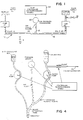
- the system of FIGURE 1 includes plural pumps (e.g. pump #1 and pump #2) interconnected by a closed fluid flow path 12 (e.g. a disposable plastic tubing as in a blood constituent processing system).
- pump #1 and pump #2 are both peristaltic pumps of conventional design.
- a fluid may be input at 14 (e.g. whole blood) and mixed with a metered supply of fluid #1 (e.g. an anticoagulant solution) while being pumped onward to other portions of the apparatus at 16 (e.g. to a plasma or platelet separator/filter device, etc.)
- Another fluid supply #2 may also be connected with pump #2 (e.g. so as to provide a source of saline solution during initial priming mode operations or the like).
- a branch 18 of the closed fluid flow path which measures the rate-of-change of fluid pressure in the path may typically include a trapped air portion communicating with an air pressure transducer 20.
- An overall system controller may include a microprocessor-based pump controller 22 which is capable of independently controlling the flow rates of pump #1 and pump #2 and which also has access to data on the rate-of-change of fluid pressure derived from the air pressure transducer 20.
- a microprocessor-based pump controller 22 which is capable of independently controlling the flow rates of pump #1 and pump #2 and which also has access to data on the rate-of-change of fluid pressure derived from the air pressure transducer 20.
- the relative pump flow calibration system includes a closed fluid flow path which has both incompressible liquids and compressible gases therewithin such that that gas pressure can be used to monitor the rate-of-change of fluid pressure.
- a relative flow rate calibration of the two pumps with respect to each other is obtained by constraining the system to pump into the closed flow path with one pump and to pump out of the closed flow path with the other pump using nominally identical flow commands. If the pumps actually have equal flow rate calibration factors, then there should be a rate-of-change of fluid pressure of zero maintained within the interconnecting closed fluid flow path. By monitoring any detected variations in the rate-of-change of fluid pressure (or contained fluid volume) within the closed fluid flow path, any calibration errors can be detected.
- the hardware architecture of the microprocessor-based pump controller 22 may be of conventional design (e.g. a microprocessor chip, RAM/ROM chips, I/O chips, analog-to-digital converters, etc. conventionally interconnected).
- the computer controlling program or software during normal system operation may be of conventional design (possibly modified so as to include a multiplicative calibration factor when generating pulp control commands).
- controller 22 also may be a "hardwired” controller.
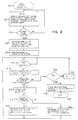
- a counter N may be reset to a contents of 1 and a visual operator display may be activated so as to request closure of the fluid path interconnecting the plural pumps in the system (e.g. by closing the valves near inlet 14 and outlet 16 or by applying suitable hemostats, clamps, etc.)
- the controller 22 may automatically close off a fluid flow path interconnecting the plural pumps in the system.
- control is passed to step 206 where pump #1 is activated to insert fluid into the closed system at a pump rate X while pump #2 is simultaneously activated to extract fluid from the closed system at pump rate Y -- the nominal pump rates X and Y being initially selected to be equal.
- a pressure reading is then taken at 208 (possibly after some finite "settling" time to permit start up of the pumps) after which a wait loop is entered at step 210 (e.g. 4.25 seconds).
- a wait loop is entered at step 210 (e.g. 4.25 seconds).
- a new pressure reading is taken at 212 and tested at 214 so as to detect any pressure changes in excess or some predetermined positive or negative "noise" value. If a significant pressure change is detected, then in block 215 a correction term proportional to the error (through multiplication factor Kg) is applied, and control is passed to block 216 where it is determined whether the pressure change is in the Increasing or decreasing direction.
- the pump rate Y of pump #2 is increased (or, alternatively, the pump rate X is decreased) by the correction term and control is passed back to the wait loop 210.
- pump rate Y is decreased (or, alternatively, pump rate X is increased) by a suitable correction term and control is again passed back to the wait loop 210.
- the N counter is tested at 222 to see if it yet equals a maximum preset value corresponding to the required time interval of approximately constant pressure. If the required constant pressure period is not yet at hand, then the N counter is incremented at 224 and control is passed back to the wait loop 210. On the other hand, after a sufficiently long period of constant pressure has been detected, then exit will be made to block 226 where the then existing relative pump rates X, Y will be stored away as pump flow calibration factors and a normal exit may be made at 228 from the pump calibrate subroutine.
- the pumps are calibrated with respect to the rate-of-change of fluid pressure or volume in the fluid path.
- the rate-of-change of fluid pressure or volume is tested so as to detect any deviations from a value of approximately zero, in which case a correction term proportional to the error is applied to determine whether there is a positive or negative deviation.
- the pump rate of at least one of the pumps #1 and #2 is controlled accordingly to maintain a rate-of-change of fluid pressure or volume in the path of approximately zero.
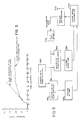
- FIG. 3 A typical graph of the rate-of-change of fluid within the closed flow path as a function of time during operation of the calibration process is depicted at Figure 3.
- an initial portion of the pressure versus time curve exhibits a slope which itself indicates the relative pump calibration error.
- the value of this slope is measured in order to calculate the appropriate pump flow calibration factors X, Y directly based upon such a slope measurement.
- slope is proportional to flow rate errors and volume of trapped air 19 (see FIGURE 1).
- Figure 4 is similar to Figure 1 but more realistically depicts a portion of a typical blood constituent processing system and a portion of a typical disposable plastic tubing harness which is typically threaded into various pumping, clamping, pressure sensing, etc. apparatus which is, in turn, under control of a microprocessor-based controller.
- a priming mode the fluid flow path between the anticoagulant pump and the blood pump is filled with liquid (thereby trapping a quantity of air in a branch of the tubing communicating with the pressure sensor).
- a hemostat or clamp is then placed at the junction of the anticoagulant tubing and of the blood extraction tubing so that the two liquids (anticoagulant solution and saline solution in this preliminary priming mode) form a closed system between the two pumps, with the air region and pressure sensor monitoring the rate-of-change of fluid pressure in the closed system.
- the rate-of-change of fluid pressure then builds up or falls as the two pumps are commanded to produce the same nominal flow rate.
- a control system such as that depicted in FIGURE 5 automatically observes the changes in the rate-of-change of fluid pressure over a time period and responsively controls at least one of the pumps to change its actual flow rate.
- the necessary calibration factor relating the relative actual flow rates of the pumps with a given disposable plastic tubing harness in place is obtained by measuring the rate-of-change of the fluid pressure.
- a modified pump flow constant may be generated so as to direct one of the pumps actually to rotate faster or slower for a specified nominal liquid flow rate. After sufficient precision has been attained, the calibration procedure is complete.
- both pumps are initially commanded to flow at a rate of 10 milliliters per minute as represented schematically at block 500 in FIGURE 5.
- This command is multiplied by an anticoagulant pump flow constant or calibration factor X at block 502 and by a blood pump flow constant or calibration factor Y at block 504 before actually being used to control the speed of the anticoagulant pump at block 506 and the blood pump at 508.
- the two pumps then act upon the closed fluid vessel system (including air) as depicted at block 510 and cause an air pressure response which is measured at block 512.
- a timed sampler 514 then feeds a gain adjustment control block 516 where the calibration factors X, Y are adjusted relative to one another so as to correct for any noted pump flow rate errors.
- the rate-of-change of fluid pressure (or volume) in the path is determined, from which flow characteristics are derived.
- Calibration factors X, Y are adjusted relative to one another on the basis of the flow characteristics so as to correct for any noted pump flow rate error.
Abstract
Description
- This invention generally relates to apparatus for calibrating relative pump flow rates between plural pumps in a common fluid flow system. The invention is particularly suited for accurately calibrating relative fluid flow rates achieved by independent pumps within a disposable plastic fluid flow path of a blood constituent processing system.
- Where plural independently controlled pumps are included in a common fluid flow system, it is sometimes necessary to accurately calibrate the relative flow rates between the various pumps within the system. For example, a typical blood constituent processing system may add a metered quantity of anticoagulant into a pumped flow of blood constituents. Such requirements may typically arise in a blood plasma filtering system (e.g. where whole blood is extracted from a donor, processed to remove plasma and to return the residual packed red blood cells to the donor) and/or in a platelet separation system (e.g. where whole blood from a donor is processed to remove platelets and/or plasma and the residual blood constituents are returned to the donor).
- In such a blood constituent processing system, there may also be a desire to accurately calibrate the relative slow rates of the blood pumped into a filter (or other fractionating device) and the packed cells output from the filter (and/or of the filtrated or separated fraction also being output from the filter).
- US-A-4086924 which is used as a basis for the preamble of
claim 1 discloses a plasmapheresis apparatus comprising a blood supply, a source of antigoagulant, a centrifuge, a blood pump and an anticoagulant pump, with the pumps being connected upstream of the centrifuge by a common open fluid path. - WO-A-8602858 discloses a blood fractionating apparatus and a method of calibrating the blood pump and the packed cells pump positioned respectively upstream and downstream of a fractionating device of the apparatus. WO-A-8602858 does not disclose a source of anticoagulant solution or an anticoagulant pump provided in the apparatus.
- In such blood constituent processing systems, for obvious health reasons, the fluid flow path is typically defined by disposable plastic tubing. Such tubing may be manually inserted into conventional pulsatile pumps (e.g. where a rotating member periodically engages and compresses the tubing in a travelling wave type of motion so as to positively displace any fluid contained within the tubing in a pulsatile manner and in a direction determined by the direction of rotation), electromagnetically operated clamps (e.g. to act as "on/off" valves which controllably pinch or close off the plastic tubing at desired control points), etc. The rotational motion of each pump may be electrically monitored using hall-effect pulse generators. In one type of system, a branched section of the tubing includes a trapped compressible gas communicating with a pressure sensor so as to permit fluid pressure variations to be monitored.
- Variations from one set of disposable plastic tubing to another (e.g., as further influenced by instantaneous variations in ambient temperature, pressures, flow rates, etc.) may cause significant flow variations. For example, in one exemplary system, the blood pump may experience flow variations of 10 to 15% and the anticoagulant pump may experience variations of up to approximately 10% due to variations from one set of disposable tubing to the next. At the same time, the metering ratio of anticoagulant flow to whole blood flow must typically be controlled with a greater precision to insure proper overall operation of the blood constituent processing system (e.g. for proper platelet survival).
- During an initial "priming" mode of such blood constituent processing systems, it is typical to have a fluid flow path (e.g. including the anticoagulant insertion line and the whole blood extraction line) disposed between two pumps (e.g. the anticoagulant metering pump and the whole blood extraction pump) filled with liquid and including an arrangement for monitoring the fluid pressure in this fluid flow path (e.g. a trapped air or other gas or fluid column extending to a pressure sensor).
- According to Claim 1 a blood fractionating apparatus comprising a first conduit means from blood supply means to a fractionating means, and a blood pump connected in said first conduit means upstream of said fractionating means, a fluid supply source connected by a second fluid conduit means with the first conduit means upstream of the blood pump, a fluid pump connected in said second conduit means for pumping said fluid from said fluid source, the pumps being connected by a common fluid path, a sensing means operable to sense changes in volume or pressure in said common fluid path, and control means connected with said sensing means and pumps, the control means being operable to cause the pumps to inject fluid into the common fluid path and withdraw fluid from the common fluid path at a respectively associated nominal rates, characterised by closure means positioned in said first conduit means upstream of the junction of the first and second conduit means to close said first conduit means to provide a closed system of said common closed fluid path connecting the pumps, the control means being operable in response to said sensing means (20) to determine the rate-of-change of fluid pressure or volume in the closed system of the common closed fluid path during said injection and withdrawal to derive relative flow characteristics of the individual pumps, which can be used to calibrate the relative flow rates of the pumps.
- According to a preferred embodiment there is provided an apparatus for more accurately calibrating the actual fluid flow rates of the anticoagulant pump and the whole blood pump during this initial "set up" or priming mode. For example, the fluid flow path extending between the two pumps is closed (e.g. by a hemastat or clamp temporarily placed at the juncture of the anticoagulant input tubing and the whole blood extraction tubing) so as to form a closed fluid system between the two pumps (e.g. typically filled with anticoagulant solution and a saline solution and a trapped air or gas region communicating with a pressure sensor). Both pumps may then be commanded to run at the same nominal flow rate and any resulting changes in the monitored rate of change of fluid pressure of the closed fluid flow system are then detected and used to adjust the commanded pumping rate of at least one of the pumps in a direction and by an amount required to null the value of such detected pressure changes with respect to time.
- Alternatively, a rate-of-change with respect to time in the liquid volume within the closed fluid system may be observed and drive to zero.
- At the end of such calibration procedure, one will know the relative pump flow control commands required to actually achieve equal flow rates and, accordingly, this provides a relative flow rate calibration factor relating the actual flow rate of one pump to the other with a particular set of disposable plastic tubing in place.
- Viewed from an overall perspective, there is described an apparatus for deriving relative flow characteristics of plural pumps fluid-connected by a common closed fluid path by measuring the rate-of-change of fluid pressure or volume in the path while one pump is injecting fluid and the other pump is withdrawing fluid from the path. The pumping rate of at least one of the pumps is adjusted in response to the derived relative flow characteristics so as to maintain a rate-of-change of fluid pressure or volume in the path of approximately zero.
- DE-A-3439661 discloses an open dialysis apparatus whose pumps can be calibrated to permit the same precision of ultrafiltration as a closed system, wherein the apparatus comprises means for measuring changes in fluid pressure or volume in a dialysis fluid path connecting a first and a second pump. In order to calibrate the pumps the fluid flow is periodically reversed therethrough and the pumping rate of at least one of the pumps is adjusted according to the measured fluid pressure or volume so as to maintain an approximately constant fluid pressure or volume in the path.
- The objects and advantages of the invention may be better appreciated by carefully studying the following detailed description of a presently preferred exemplary embodiment, when taken in conjunction with the accompanying drawings, of which:
- FIGURE 1 is a schematic block diagram of an apparatus according to the present invention, the apparatus having plural pumps and a closed fluid path;
- FIGURE 2 is a flow diagram of a computer controlling subroutine or program useable for the pump controller of FIGURE 1;
- FIGURE 3 is an explanatory graph depicting a typical rate-of-change of fluid pressure with respect to time in the closed fluid flow path of FIGURE 1;
- FIGURE 4 is a schematic depiction of a portion of a blood constituent processing system which embodies a closed fluid flow path between two independently controlled pumps in a manner which is similar to that depicted in FIGURE 1;
- FIGURE 5 is a schematic block diagram of a control system which may be suitable for use as the controller in the apparatus of FIGURES 1 and/or 4.
- The system of FIGURE 1 includes plural pumps (
e.g. pump # 1 and pump #2) interconnected by a closed fluid flow path 12 (e.g. a disposable plastic tubing as in a blood constituent processing system). In the exemplary embodiment,pump # 1 andpump # 2 are both peristaltic pumps of conventional design. During sustained system operation, a fluid may be input at 14 (e.g. whole blood) and mixed with a metered supply of fluid #1 (e.g. an anticoagulant solution) while being pumped onward to other portions of the apparatus at 16 (e.g. to a plasma or platelet separator/filter device, etc.) Anotherfluid supply # 2 may also be connected with pump #2 (e.g. so as to provide a source of saline solution during initial priming mode operations or the like). Abranch 18 of the closed fluid flow path which measures the rate-of-change of fluid pressure in the path may typically include a trapped air portion communicating with anair pressure transducer 20. An overall system controller may include a microprocessor-basedpump controller 22 which is capable of independently controlling the flow rates ofpump # 1 andpump # 2 and which also has access to data on the rate-of-change of fluid pressure derived from theair pressure transducer 20. Those in the art will recognize that there may be many other configurations of a closed fluid flow path extending between plural pumps which may be independently controlled and for which accurate relative flow rate calibration factors are desired. - In this exemplary embodiment, the relative pump flow calibration system includes a closed fluid flow path which has both incompressible liquids and compressible gases therewithin such that that gas pressure can be used to monitor the rate-of-change of fluid pressure. A relative flow rate calibration of the two pumps with respect to each other is obtained by constraining the system to pump into the closed flow path with one pump and to pump out of the closed flow path with the other pump using nominally identical flow commands. If the pumps actually have equal flow rate calibration factors, then there should be a rate-of-change of fluid pressure of zero maintained within the interconnecting closed fluid flow path. By monitoring any detected variations in the rate-of-change of fluid pressure (or contained fluid volume) within the closed fluid flow path, any calibration errors can be detected.
- The hardware architecture of the microprocessor-based
pump controller 22 may be of conventional design (e.g. a microprocessor chip, RAM/ROM chips, I/O chips, analog-to-digital converters, etc. conventionally interconnected). The computer controlling program or software during normal system operation may be of conventional design (possibly modified so as to include a multiplicative calibration factor when generating pulp control commands). - However, the
controller 22 also may be a "hardwired" controller. - Referring to FIGURE 2, upon entry into the
pump calibrate subroutine 200, some initial "housekeeping" details may be attended to such as those depicted atblock 202. For example, a counter N may be reset to a contents of 1 and a visual operator display may be activated so as to request closure of the fluid path interconnecting the plural pumps in the system (e.g. by closing the valves nearinlet 14 andoutlet 16 or by applying suitable hemostats, clamps, etc.) Alternatively, if the system includes suitably placed electromagnetically controlled tubing clamps or the like, then thecontroller 22 may automatically close off a fluid flow path interconnecting the plural pumps in the system. - A check may be made at
step 204 for the existence of a closed fluid system (e.g. by monitoring a manually activated switch and/or by performing automated stimulus/response testing routines as will be apparent). Once a properly closed fluid system is in place, control is passed to step 206 wherepump # 1 is activated to insert fluid into the closed system at a pump rate X whilepump # 2 is simultaneously activated to extract fluid from the closed system at pump rate Y -- the nominal pump rates X and Y being initially selected to be equal. - As known in the art, a pressure reading is then taken at 208 (possibly after some finite "settling" time to permit start up of the pumps) after which a wait loop is entered at step 210 (e.g. 4.25 seconds). Upon exit from the
wait loop 210, a new pressure reading is taken at 212 and tested at 214 so as to detect any pressure changes in excess or some predetermined positive or negative "noise" value. If a significant pressure change is detected, then in block 215 a correction term proportional to the error (through multiplication factor Kg) is applied, and control is passed toblock 216 where it is determined whether the pressure change is in the Increasing or decreasing direction. If the pressure change increased, then the pump rate Y ofpump # 2 is increased (or, alternatively, the pump rate X is decreased) by the correction term and control is passed back to thewait loop 210. On the other hand, if the pressure change was in the decreasing direction, then pump rate Y is decreased (or, alternatively, pump rate X is increased) by a suitable correction term and control is again passed back to thewait loop 210. - If no significant pressure change is observed, then the N counter is tested at 222 to see if it yet equals a maximum preset value corresponding to the required time interval of approximately constant pressure. If the required constant pressure period is not yet at hand, then the N counter is incremented at 224 and control is passed back to the
wait loop 210. On the other hand, after a sufficiently long period of constant pressure has been detected, then exit will be made to block 226 where the then existing relative pump rates X, Y will be stored away as pump flow calibration factors and a normal exit may be made at 228 from the pump calibrate subroutine. - The pumps are calibrated with respect to the rate-of-change of fluid pressure or volume in the fluid path. The rate-of-change of fluid pressure or volume is tested so as to detect any deviations from a value of approximately zero, in which case a correction term proportional to the error is applied to determine whether there is a positive or negative deviation. The pump rate of at least one of the
pumps # 1 and #2 is controlled accordingly to maintain a rate-of-change of fluid pressure or volume in the path of approximately zero. - A typical graph of the rate-of-change of fluid within the closed flow path as a function of time during operation of the calibration process is depicted at Figure 3. Here, it will be seen that an initial portion of the pressure versus time curve exhibits a slope which itself indicates the relative pump calibration error. The value of this slope is measured in order to calculate the appropriate pump flow calibration factors X, Y directly based upon such a slope measurement. Of course, such measurement involves some error since slope is proportional to flow rate errors and volume of trapped air 19 (see FIGURE 1). After matched pump calibration has been achieved, it will be seen in Figure 3 that the slope of the pressure versus time curve (i.e. rate-of-change of pressure) reduces to an approximately zero value.
- Figure 4 is similar to Figure 1 but more realistically depicts a portion of a typical blood constituent processing system and a portion of a typical disposable plastic tubing harness which is typically threaded into various pumping, clamping, pressure sensing, etc. apparatus which is, in turn, under control of a microprocessor-based controller. During a priming mode, the fluid flow path between the anticoagulant pump and the blood pump is filled with liquid (thereby trapping a quantity of air in a branch of the tubing communicating with the pressure sensor). A hemostat or clamp is then placed at the junction of the anticoagulant tubing and of the blood extraction tubing so that the two liquids (anticoagulant solution and saline solution in this preliminary priming mode) form a closed system between the two pumps, with the air region and pressure sensor monitoring the rate-of-change of fluid pressure in the closed system.
- The rate-of-change of fluid pressure then builds up or falls as the two pumps are commanded to produce the same nominal flow rate. A control system such as that depicted in FIGURE 5 automatically observes the changes in the rate-of-change of fluid pressure over a time period and responsively controls at least one of the pumps to change its actual flow rate. In this way the necessary calibration factor relating the relative actual flow rates of the pumps with a given disposable plastic tubing harness in place is obtained by measuring the rate-of-change of the fluid pressure. Hence, a modified pump flow constant may be generated so as to direct one of the pumps actually to rotate faster or slower for a specified nominal liquid flow rate. After sufficient precision has been attained, the calibration procedure is complete.
- As depicted in FIGURE 5, both pumps are initially commanded to flow at a rate of 10 milliliters per minute as represented schematically at
block 500 in FIGURE 5. This command is multiplied by an anticoagulant pump flow constant or calibration factor X atblock 502 and by a blood pump flow constant or calibration factor Y atblock 504 before actually being used to control the speed of the anticoagulant pump at block 506 and the blood pump at 508. The two pumps then act upon the closed fluid vessel system (including air) as depicted atblock 510 and cause an air pressure response which is measured atblock 512. Atimed sampler 514 then feeds a gainadjustment control block 516 where the calibration factors X, Y are adjusted relative to one another so as to correct for any noted pump flow rate errors. The rate-of-change of fluid pressure (or volume) in the path is determined, from which flow characteristics are derived. Calibration factors X, Y are adjusted relative to one another on the basis of the flow characteristics so as to correct for any noted pump flow rate error. - If pulsatile pumps are employed, there will, of course, be periodic pressure/volume pulses which may be disregarded (e.g., by employing suitable low pass "averaging" filters) in the calibration procedures.
Claims (5)
- A blood fractionating apparatus comprising a first conduit means from blood supply means (14) to a fractionating means, and a blood pump (#2) connected in said first conduit means upstream of said fractionating means, a fluid supply source (#1) connected by a second fluid conduit means with the first conduit means upstream of the blood pump (#2), a fluid pump (#1) connected in said second conduit means for pumping said fluid from said fluid source (#1), the pumps being connected by a common fluid path, a sensing means (20) operable to sense changes in volume or pressure in said common fluid path, and control means (22) connected with said sensing means (20) and pumps (#1,#2), the control means being operable to cause the pumps (#1,#2) to inject fluid into the common fluid path and withdraw fluid from the common fluid path at a respectively associated nominal rates, characterised by closure means positioned in said first conduit means upstream of the junction of the first and second conduit means to close said first conduit means to provide a closed system of said common fluid path connecting the pumps (#1,#2), the control means (22) being operable in response to said sensing means (20) to determine the rate-of-change of fluid pressure or volume in the closed system of the common fluid path during said injection and withdrawal to derive relative flow characteristics of the individual pumps (#1,#2) which can be used to calibrate the relative flow rates of the pumps (#1,#2).
- Apparatus as in Claim 1, comprising during a preliminary set-up period a source (#2) of saline solution connected with said first conduit means downstream of said blood pump (#2), and wherein said fluid supply source (#1) is a source of anticoagulant solution and said pumps (#1,#2) initially have nominal pumping flow rates which are assumed to be equal.
- Apparatus as in Claim 1 or 2 wherein said control means (22) is operable to control the nominal rate of at least one of said pumps (#1,#2) in response to said relative flow characteristics so as to maintain a rate-of-change of fluid pressure or volume in said common closed fluid path of approximately zero.
- Apparatus as in Claim 3 wherein said control means (22) is operable to record the relationship between the nominal pump flow rates required to maintain said approximately zero rate-of-change of fluid pressure or volume.
- Apparatus as in any preceding claim wherein said control means (22) is operable to determine the time-based rate of pressure or volume change in said common closed path.
Applications Claiming Priority (1)
| Application Number | Priority Date | Filing Date | Title |
|---|---|---|---|
| PCT/US1987/000354 WO1988006466A1 (en) | 1987-02-25 | 1987-02-25 | Calibrating plural pump fluid flow system |
Related Child Applications (1)
| Application Number | Title | Priority Date | Filing Date |
|---|---|---|---|
| EP93202643.8 Division-Into | 1993-09-13 |
Publications (3)
| Publication Number | Publication Date |
|---|---|
| EP0302861A1 EP0302861A1 (en) | 1989-02-15 |
| EP0302861A4 EP0302861A4 (en) | 1990-04-10 |
| EP0302861B1 true EP0302861B1 (en) | 1995-12-27 |
Family
ID=22202291
Family Applications (2)
| Application Number | Title | Priority Date | Filing Date |
|---|---|---|---|
| EP93202643A Expired - Lifetime EP0578338B1 (en) | 1987-02-25 | 1987-02-25 | Calibrating plural pump fluid flow system |
| EP87901906A Expired - Lifetime EP0302861B1 (en) | 1987-02-25 | 1987-02-25 | Calibrating plural pump fluid flow system |
Family Applications Before (1)
| Application Number | Title | Priority Date | Filing Date |
|---|---|---|---|
| EP93202643A Expired - Lifetime EP0578338B1 (en) | 1987-02-25 | 1987-02-25 | Calibrating plural pump fluid flow system |
Country Status (6)
| Country | Link |
|---|---|
| US (1) | US4769001A (en) |
| EP (2) | EP0578338B1 (en) |
| JP (1) | JP2847161B2 (en) |
| AU (1) | AU597637B2 (en) |
| DE (2) | DE3752055T2 (en) |
| WO (1) | WO1988006466A1 (en) |
Families Citing this family (101)
| Publication number | Priority date | Publication date | Assignee | Title |
|---|---|---|---|---|
| US4747822A (en) * | 1984-07-09 | 1988-05-31 | Peabody Alan M | Continuous flow peritoneal dialysis system and method |
| DE3805368C1 (en) * | 1988-02-17 | 1989-08-24 | Peter P. Dipl.-Ing. Wiest | |
| DE3806248A1 (en) * | 1988-02-27 | 1989-09-07 | Fresenius Ag | MEASURING / DISPLAYING METHOD FOR LIQUID SYSTEMS OF MEDICAL DEVICES AND DEVICE FOR IMPLEMENTING THE METHOD |
| NL8801400A (en) * | 1988-06-01 | 1990-01-02 | Akzo Nv | Apparatus for withdrawing an optimum amount of blood per unit time from a donor. |
| DE3837298C1 (en) * | 1988-11-03 | 1990-03-29 | Fresenius Ag, 6380 Bad Homburg, De | |
| DE3933856A1 (en) * | 1989-10-07 | 1991-04-18 | Wiest Peter P | DEVICE FOR RINSING AND SUCTIONING BODY CAVES |
| US5141501A (en) * | 1990-05-21 | 1992-08-25 | Vernay Laboratories, Inc. | Suction metering and mixing device |
| US5163926A (en) * | 1990-05-21 | 1992-11-17 | Vernay Laboratories, Inc. | Suction metering and mixing device |
| US5135667A (en) * | 1990-06-14 | 1992-08-04 | Baxter International Inc. | Method and apparatus for administration of anticoagulant to red cell suspension output of a blood separator |
| US5171456A (en) * | 1990-06-14 | 1992-12-15 | Baxter International Inc. | Automated blood component separation procedure and apparatus promoting different functional characteristics in multiple blood components |
| GB2247317B (en) * | 1990-08-13 | 1994-05-04 | Danby Medical Ltd | A device for monitoring pressure in a fluid flow system |
| US5114672A (en) * | 1990-08-27 | 1992-05-19 | Cryo-Cell International, Inc. | Method for preserving blood fluid |
| US5098384A (en) * | 1991-01-23 | 1992-03-24 | Abrams Lawrence M | Pressure-compensated fluid administering apparatus |
| US5322500A (en) * | 1991-05-09 | 1994-06-21 | Cardio Pulmonary Supplies, Inc. | Variable ratio blood-additive solution device and delivery system |
| US5676841A (en) * | 1991-12-23 | 1997-10-14 | Baxter International Inc. | Blood processing systems and methods which monitor citrate return to the donor |
| US5833866A (en) * | 1991-12-23 | 1998-11-10 | Baxter International Inc. | Blood collection systems and methods which derive instantaneous blood component yield information during blood processing |
| US5639382A (en) * | 1991-12-23 | 1997-06-17 | Baxter International Inc. | Systems and methods for deriving recommended storage parameters for collected blood components |
| US5681273A (en) * | 1991-12-23 | 1997-10-28 | Baxter International Inc. | Systems and methods for predicting blood processing parameters |
| US6007725A (en) | 1991-12-23 | 1999-12-28 | Baxter International Inc. | Systems and methods for on line collection of cellular blood components that assure donor comfort |
| US5690835A (en) | 1991-12-23 | 1997-11-25 | Baxter International Inc. | Systems and methods for on line collection of cellular blood components that assure donor comfort |
| US5730883A (en) | 1991-12-23 | 1998-03-24 | Baxter International Inc. | Blood processing systems and methods using apparent hematocrit as a process control parameter |
| US5527161A (en) * | 1992-02-13 | 1996-06-18 | Cybor Corporation | Filtering and dispensing system |
| US5195967A (en) * | 1992-02-18 | 1993-03-23 | Nakao Naomi L | Anticlotting device and method for use with IV catheters |
| US5817042A (en) * | 1992-03-04 | 1998-10-06 | Cobe Laboratories, Inc. | Method and apparatus for controlling concentrations in vivos and in tubing systems |
| US5421812A (en) * | 1992-03-04 | 1995-06-06 | Cobe Laboratories, Inc. | Method and apparatus for controlling concentrations in tubing system |
| US5676645A (en) * | 1992-03-04 | 1997-10-14 | Cobe Laboratories, Inc. | Method and apparatus for controlling concentrations in vivos and in tubing systems |
| US5378227A (en) * | 1992-08-11 | 1995-01-03 | Cobe Laboratories, Inc. | Biological/pharmaceutical method and apparatus for collecting and mixing fluids |
| US5490765A (en) * | 1993-05-17 | 1996-02-13 | Cybor Corporation | Dual stage pump system with pre-stressed diaphragms and reservoir |
| US5856929A (en) * | 1994-08-19 | 1999-01-05 | Spectrel Partners, L.L.C. | Integrated systems for testing and certifying the physical, functional, and electrical performance of IV pumps |
| US5717603A (en) * | 1994-08-19 | 1998-02-10 | Spectrel Partners, L.L.C. | Integrated test station for testing liquid flow and electrical safety characteristics of IV pumps |
| US6757630B2 (en) * | 1994-08-19 | 2004-06-29 | Mediq/Prn Life Support Services, Inc. | Integrated systems for testing and certifying the physical, functional, and electrical performance of IV pumps |
| US5608650A (en) * | 1994-08-19 | 1997-03-04 | Spectrel Partners, L.L.C. | Systems and methods for testing pump flow rates |
| US5697899A (en) * | 1995-02-07 | 1997-12-16 | Gensia | Feedback controlled drug delivery system |
| WO1996025186A2 (en) * | 1995-02-07 | 1996-08-22 | Gensia, Inc. | Feedback controlled drug delivery system |
| US5691478A (en) * | 1995-06-07 | 1997-11-25 | Schneider/Namic | Device and method for remote zeroing of a biological fluid pressure measurement device |
| US5759413A (en) | 1995-06-07 | 1998-06-02 | Baxter International Inc. | Systems and method for estimating platelet counts using a spleen mobilization function |
| US6251284B1 (en) | 1995-08-09 | 2001-06-26 | Baxter International Inc. | Systems and methods which obtain a uniform targeted volume of concentrated red blood cells in diverse donor populations |
| US5762791A (en) * | 1995-08-09 | 1998-06-09 | Baxter International Inc. | Systems for separating high hematocrit red blood cell concentrations |
| US6527957B1 (en) | 1995-08-09 | 2003-03-04 | Baxter International Inc. | Methods for separating, collecting and storing red blood cells |
| US5752931A (en) * | 1996-09-30 | 1998-05-19 | Minnesota Mining And Manufacturing Company | Perfusion system with perfusion circuit display |
| US5813972A (en) * | 1996-09-30 | 1998-09-29 | Minnesota Mining And Manufacturing Company | Medical perfusion system with data communications network |
| US7148786B2 (en) * | 1996-09-30 | 2006-12-12 | Terumo Cardiovascular Systems Corporation | Network communication and message protocol for a medical perfusion system |
| US6164920A (en) * | 1996-09-30 | 2000-12-26 | Minnesota Mining And Manufacturing Company | Perfusion system with control network |
| WO1998014225A2 (en) * | 1996-10-04 | 1998-04-09 | United States Surgical Corporation | Circulatory support system |
| US5927349A (en) | 1996-12-09 | 1999-07-27 | Baxter International Inc. | Compounding assembly for nutritional fluids |
| US5984893A (en) * | 1997-03-27 | 1999-11-16 | Ward; Roger T. | Blood infusion control system |
| WO2000009182A1 (en) | 1998-08-11 | 2000-02-24 | Alpamed S.A. | Fluid driving device |
| US6199603B1 (en) | 1998-08-14 | 2001-03-13 | Baxter International Inc. | Compounding assembly for nutritional fluids |
| US6691047B1 (en) | 2000-03-16 | 2004-02-10 | Aksys, Ltd. | Calibration of pumps, such as blood pumps of dialysis machine |
| FR2850581B1 (en) * | 2003-02-03 | 2005-09-09 | Maco Pharma Sa | PRECAUTIONED LOOP PICKUP SYSTEM |
| US8672875B2 (en) * | 2003-12-31 | 2014-03-18 | Carefusion 303, Inc. | Medication safety enhancement for secondary infusion |
| US7206715B2 (en) * | 2003-12-31 | 2007-04-17 | Cardinal Health 303, Inc. | Empty container detection using container side pressure sensing |
| US7255683B2 (en) * | 2003-12-31 | 2007-08-14 | Cardinal Health 303, Inc. | System for detecting the status of a vent associated with a fluid supply upstream of an infusion pump |
| US7087177B2 (en) * | 2004-04-16 | 2006-08-08 | Baxter International Inc. | Methods for determining flow rates of biological fluids |
| SG122835A1 (en) * | 2004-12-01 | 2006-06-29 | Univ Singapore | Umbilical cord blood collection apparatus |
| US7775966B2 (en) | 2005-02-24 | 2010-08-17 | Ethicon Endo-Surgery, Inc. | Non-invasive pressure measurement in a fluid adjustable restrictive device |
| US7927270B2 (en) | 2005-02-24 | 2011-04-19 | Ethicon Endo-Surgery, Inc. | External mechanical pressure sensor for gastric band pressure measurements |
| US7699770B2 (en) | 2005-02-24 | 2010-04-20 | Ethicon Endo-Surgery, Inc. | Device for non-invasive measurement of fluid pressure in an adjustable restriction device |
| US7658196B2 (en) | 2005-02-24 | 2010-02-09 | Ethicon Endo-Surgery, Inc. | System and method for determining implanted device orientation |
| US8066629B2 (en) | 2005-02-24 | 2011-11-29 | Ethicon Endo-Surgery, Inc. | Apparatus for adjustment and sensing of gastric band pressure |
| US7775215B2 (en) | 2005-02-24 | 2010-08-17 | Ethicon Endo-Surgery, Inc. | System and method for determining implanted device positioning and obtaining pressure data |
| US8016744B2 (en) | 2005-02-24 | 2011-09-13 | Ethicon Endo-Surgery, Inc. | External pressure-based gastric band adjustment system and method |
| US8092414B2 (en) | 2005-11-09 | 2012-01-10 | Nxstage Medical, Inc. | Diaphragm pressure pod for medical fluids |
| JP4853956B2 (en) * | 2006-04-05 | 2012-01-11 | 日機装株式会社 | Blood circuit priming method |
| US8870742B2 (en) | 2006-04-06 | 2014-10-28 | Ethicon Endo-Surgery, Inc. | GUI for an implantable restriction device and a data logger |
| US8152710B2 (en) | 2006-04-06 | 2012-04-10 | Ethicon Endo-Surgery, Inc. | Physiological parameter analysis for an implantable restriction device and a data logger |
| WO2007133259A1 (en) | 2006-04-18 | 2007-11-22 | Gambro Bct, Inc. | Extracorporeal blood processing apparatus with pump balancing |
| US8475138B2 (en) * | 2007-08-27 | 2013-07-02 | Quest Medical, Inc. | Self-adaptive piston blood pump |
| US8187163B2 (en) | 2007-12-10 | 2012-05-29 | Ethicon Endo-Surgery, Inc. | Methods for implanting a gastric restriction device |
| US8100870B2 (en) | 2007-12-14 | 2012-01-24 | Ethicon Endo-Surgery, Inc. | Adjustable height gastric restriction devices and methods |
| US8377079B2 (en) | 2007-12-27 | 2013-02-19 | Ethicon Endo-Surgery, Inc. | Constant force mechanisms for regulating restriction devices |
| US8142452B2 (en) | 2007-12-27 | 2012-03-27 | Ethicon Endo-Surgery, Inc. | Controlling pressure in adjustable restriction devices |
| US8591395B2 (en) | 2008-01-28 | 2013-11-26 | Ethicon Endo-Surgery, Inc. | Gastric restriction device data handling devices and methods |
| US8192350B2 (en) | 2008-01-28 | 2012-06-05 | Ethicon Endo-Surgery, Inc. | Methods and devices for measuring impedance in a gastric restriction system |
| US8337389B2 (en) | 2008-01-28 | 2012-12-25 | Ethicon Endo-Surgery, Inc. | Methods and devices for diagnosing performance of a gastric restriction system |
| US7844342B2 (en) | 2008-02-07 | 2010-11-30 | Ethicon Endo-Surgery, Inc. | Powering implantable restriction systems using light |
| US8221439B2 (en) | 2008-02-07 | 2012-07-17 | Ethicon Endo-Surgery, Inc. | Powering implantable restriction systems using kinetic motion |
| US8114345B2 (en) | 2008-02-08 | 2012-02-14 | Ethicon Endo-Surgery, Inc. | System and method of sterilizing an implantable medical device |
| US8591532B2 (en) | 2008-02-12 | 2013-11-26 | Ethicon Endo-Sugery, Inc. | Automatically adjusting band system |
| US8057492B2 (en) | 2008-02-12 | 2011-11-15 | Ethicon Endo-Surgery, Inc. | Automatically adjusting band system with MEMS pump |
| US8034065B2 (en) | 2008-02-26 | 2011-10-11 | Ethicon Endo-Surgery, Inc. | Controlling pressure in adjustable restriction devices |
| US8233995B2 (en) | 2008-03-06 | 2012-07-31 | Ethicon Endo-Surgery, Inc. | System and method of aligning an implantable antenna |
| US8187162B2 (en) | 2008-03-06 | 2012-05-29 | Ethicon Endo-Surgery, Inc. | Reorientation port |
| EP2343092B2 (en) | 2009-12-22 | 2016-07-13 | Gambro Lundia AB | Method and apparatus for controlling a fluid flow rate in a fluid transport line of a medical device |
| US9603989B2 (en) | 2010-08-24 | 2017-03-28 | Fenwal, Inc. | Methods for anticoagulating blood |
| HUE033095T2 (en) * | 2011-05-27 | 2017-11-28 | Grifols Sa | Priming anticoagulant line for blood extraction |
| DE112012002327T5 (en) | 2011-05-31 | 2014-03-27 | Nxstage Medical, Inc. | Pressure measuring device, methods and systems |
| AU2012299169B2 (en) | 2011-08-19 | 2017-08-24 | Icu Medical, Inc. | Systems and methods for a graphical interface including a graphical representation of medical data |
| ES2741725T3 (en) | 2012-03-30 | 2020-02-12 | Icu Medical Inc | Air detection system and method to detect air in a pump of an infusion system |
| WO2014007742A1 (en) * | 2012-07-05 | 2014-01-09 | Stroemberg Lennart | Blood collection system and method |
| US10463788B2 (en) | 2012-07-31 | 2019-11-05 | Icu Medical, Inc. | Patient care system for critical medications |
| EP3003442B1 (en) | 2013-05-29 | 2020-12-30 | ICU Medical, Inc. | Infusion system and method of use which prevents over-saturation of an analog-to-digital converter |
| WO2015007596A1 (en) | 2013-07-15 | 2015-01-22 | Gambro Lundia Ab | Relative pump calibration for ultrafiltration control in a dialysis apparatus |
| CN104470553B (en) | 2013-07-15 | 2017-02-22 | 甘布罗伦迪亚股份公司 | Individual Pump Calibration For Ultrafiltration Control In A Dialysis Apparatus |
| US10525182B2 (en) | 2014-10-10 | 2020-01-07 | Nxstage Medical, Inc. | Flow balancing devices, methods, and systems |
| EP3031485B1 (en) * | 2014-12-10 | 2018-11-21 | B. Braun Avitum AG | Method and control apparatus for determining and adjusting a flow rate of a blood delivery pump |
| JP7086926B2 (en) | 2016-07-18 | 2022-06-20 | ネクステージ メディカル インコーポレイテッド | Flow balancing equipment, methods, and systems |
| US10089055B1 (en) | 2017-12-27 | 2018-10-02 | Icu Medical, Inc. | Synchronized display of screen content on networked devices |
| WO2021236465A1 (en) * | 2020-05-19 | 2021-11-25 | Life Technologies Corporation | Dual-stage fluidics system with reduced pulsation |
| WO2022020184A1 (en) | 2020-07-21 | 2022-01-27 | Icu Medical, Inc. | Fluid transfer devices and methods of use |
| US11135360B1 (en) * | 2020-12-07 | 2021-10-05 | Icu Medical, Inc. | Concurrent infusion with common line auto flush |
Citations (1)
| Publication number | Priority date | Publication date | Assignee | Title |
|---|---|---|---|---|
| WO1986002858A1 (en) * | 1984-11-15 | 1986-05-22 | Hemascience Laboratories, Inc. | Adaptive filter concentrate flow control system and method |
Family Cites Families (21)
| Publication number | Priority date | Publication date | Assignee | Title |
|---|---|---|---|---|
| US3817658A (en) * | 1971-03-22 | 1974-06-18 | Tokyo Heat Treating | Fluid control apparatus |
| US4086924A (en) * | 1976-10-06 | 1978-05-02 | Haemonetics Corporation | Plasmapheresis apparatus |
| US4197847A (en) * | 1977-03-31 | 1980-04-15 | Isaac Djerassi | Method and apparatus for collecting transfusable granulocytes |
| US4379452A (en) * | 1977-10-18 | 1983-04-12 | Baxter Travenol Laboratories, Inc. | Prepackaged, self-contained fluid circuit module |
| US4303193A (en) * | 1979-01-22 | 1981-12-01 | Haemonetics Corporation | Apparatus for separating blood into components thereof |
| US4285464A (en) * | 1979-01-22 | 1981-08-25 | Haemonetics Corporation | Apparatus for separation of blood into components thereof |
| US4280494A (en) * | 1979-06-26 | 1981-07-28 | Cosgrove Robert J Jun | System for automatic feedback-controlled administration of drugs |
| US4526515A (en) * | 1979-12-06 | 1985-07-02 | Baxter Travenol Laboratories, Inc. | Fluid pumping assembly including a prepackaged fluid circuit module |
| US4392849A (en) * | 1981-07-27 | 1983-07-12 | The Cleveland Clinic Foundation | Infusion pump controller |
| US4416654A (en) * | 1981-09-03 | 1983-11-22 | Haemonetics Corporation | Pheresis apparatus |
| US4464167A (en) * | 1981-09-03 | 1984-08-07 | Haemonetics Corporation | Pheresis apparatus |
| US4481827A (en) * | 1981-12-15 | 1984-11-13 | Baxter Travenol Laboratories, Inc. | Blood fractionation apparatus having collection rate display system |
| US4493693A (en) * | 1982-07-30 | 1985-01-15 | Baxter Travenol Laboratories, Inc. | Trans-membrane pressure monitoring system |
| US4563173A (en) * | 1983-04-19 | 1986-01-07 | National Biomedical Research Foundation | Pump-actuated sequencing valve and system |
| US4605503A (en) * | 1983-05-26 | 1986-08-12 | Baxter Travenol Laboratories, Inc. | Single needle blood fractionation system having adjustable recirculation through filter |
| US4498983A (en) * | 1983-05-26 | 1985-02-12 | Baxter Travenol Laboratories, Inc. | Pressure cuff draw mode enhancement system and method for a single needle blood fractionation system |
| FR2548541B1 (en) * | 1983-07-07 | 1986-09-12 | Rhone Poulenc Sa | PLASMAPHERESE PROCESS AND APPARATUS FOR USE IN PARTICULAR FOR THIS PROCESS |
| US4468219A (en) * | 1983-12-20 | 1984-08-28 | International Business Machines Corporation | Pump flow rate compensation system |
| ATE70193T1 (en) * | 1984-06-29 | 1991-12-15 | Baxter Int | METHOD AND DEVICE FOR CONTROLLING THE COLLECTION AND SUBSEQUENT INFUSION OF BLOOD. |
| DE3439661A1 (en) * | 1984-10-30 | 1986-05-07 | Fresenius AG, 6380 Bad Homburg | Haemodialysis unit |
| FR2581316A1 (en) * | 1985-05-02 | 1986-11-07 | Murisasco Antoine | Method and device for automatic plasma exchanges controlled by an integrated computer |
-
1985
- 1985-11-27 US US06/802,330 patent/US4769001A/en not_active Expired - Lifetime
-
1987
- 1987-02-25 WO PCT/US1987/000354 patent/WO1988006466A1/en active IP Right Grant
- 1987-02-25 EP EP93202643A patent/EP0578338B1/en not_active Expired - Lifetime
- 1987-02-25 AU AU71211/87A patent/AU597637B2/en not_active Ceased
- 1987-02-25 DE DE3752055T patent/DE3752055T2/en not_active Expired - Fee Related
- 1987-02-25 DE DE3751656T patent/DE3751656T2/en not_active Expired - Fee Related
- 1987-02-25 EP EP87901906A patent/EP0302861B1/en not_active Expired - Lifetime
- 1987-02-25 JP JP62501634A patent/JP2847161B2/en not_active Expired - Fee Related
Patent Citations (1)
| Publication number | Priority date | Publication date | Assignee | Title |
|---|---|---|---|---|
| WO1986002858A1 (en) * | 1984-11-15 | 1986-05-22 | Hemascience Laboratories, Inc. | Adaptive filter concentrate flow control system and method |
Also Published As
| Publication number | Publication date |
|---|---|
| AU7121187A (en) | 1988-09-26 |
| US4769001A (en) | 1988-09-06 |
| WO1988006466A1 (en) | 1988-09-07 |
| JP2847161B2 (en) | 1999-01-13 |
| EP0578338B1 (en) | 1997-04-23 |
| EP0302861A1 (en) | 1989-02-15 |
| DE3752055D1 (en) | 1997-05-28 |
| DE3752055T2 (en) | 1997-11-20 |
| EP0578338A3 (en) | 1994-03-02 |
| DE3751656T2 (en) | 1996-09-05 |
| DE3751656D1 (en) | 1996-02-08 |
| EP0302861A4 (en) | 1990-04-10 |
| EP0578338A2 (en) | 1994-01-12 |
| AU597637B2 (en) | 1990-06-07 |
| JPH01503198A (en) | 1989-11-02 |
Similar Documents
| Publication | Publication Date | Title |
|---|---|---|
| EP0302861B1 (en) | Calibrating plural pump fluid flow system | |
| US4964847A (en) | Method and apparatus for estimating hematocrit in a blood constituent processing system | |
| EP1458431B1 (en) | Equipment for controlling blood flow in an extracorporeal blood circuit | |
| US6066261A (en) | Method of monitoring part of a blood treatment machine and a blood treatment machine with a monitoring device | |
| US6156002A (en) | Method of measuring the efficiency of mass and energy transfer in hemodialysis | |
| US4464164A (en) | Flowrate control for a blood flow system | |
| JP4384418B2 (en) | Method and apparatus for detecting leakage in a fluid system of a blood processing apparatus | |
| US4614590A (en) | Dialysis apparatus and method for its control | |
| US4889635A (en) | Method and apparatus for controlling the quantities of liquid circulating in the dialysis liquid circuit of an artificial kidney | |
| US8529767B2 (en) | Method for determining the percentage of recirculation in a fistula and/or cardiopulmonary recirculation relative to the total fistula recirculation and cardiopulmonary recirculation | |
| EP1078642A2 (en) | Measuring and/or monitoring method, especially for the evaluation of pressure differences | |
| JPH07506A (en) | Equipment and method for controlling balance of fluid in external blood circuit | |
| JPS63308519A (en) | Improved flow rate measuring system | |
| US8182691B2 (en) | Apparatus for extracorporeal blood treatment with a device for checking a sterile filter, and method of checking a sterile filter of an extracorporeal blood treatment apparatus | |
| US11083829B2 (en) | Medical treatment device and method for monitoring a medical treatment device | |
| US7704213B2 (en) | Method and device for determining the blood flow in a blood-conducting tube | |
| US4758336A (en) | Dialytic apparatus | |
| EP2676688A1 (en) | A method and a device for monitoring a state of a blood line in a machine for extracorporeal blood treatment | |
| EP0226720A1 (en) | A blood filtering system comprising an arrangement for the prevention of back flow | |
| CA1288610C (en) | Method and apparatus for calibrating plural pump fluid flow system | |
| CN117479966A (en) | Device for extracorporeal blood treatment | |
| JPH0622622B2 (en) | Blood purification device | |
| JPH0221872A (en) | Blood plasma separating device and control method therefor |
Legal Events
| Date | Code | Title | Description |
|---|---|---|---|
| PUAI | Public reference made under article 153(3) epc to a published international application that has entered the european phase |
Free format text: ORIGINAL CODE: 0009012 |
|
| 17P | Request for examination filed |
Effective date: 19881104 |
|
| AK | Designated contracting states |
Kind code of ref document: A1 Designated state(s): BE CH DE FR GB IT LI NL SE |
|
| A4 | Supplementary search report drawn up and despatched |
Effective date: 19900410 |
|
| RAP1 | Party data changed (applicant data changed or rights of an application transferred) |
Owner name: BAXTER INTERNATIONAL INC. (A DELAWARE CORPORATION) |
|
| 17Q | First examination report despatched |
Effective date: 19910916 |
|
| GRAA | (expected) grant |
Free format text: ORIGINAL CODE: 0009210 |
|
| AK | Designated contracting states |
Kind code of ref document: B1 Designated state(s): BE CH DE FR GB IT LI NL SE |
|
| XX | Miscellaneous (additional remarks) |
Free format text: TEILANMELDUNG 93202643.8 EINGEREICHT AM 25/02/87. |
|
| REF | Corresponds to: |
Ref document number: 3751656 Country of ref document: DE Date of ref document: 19960208 |
|
| ET | Fr: translation filed | ||
| ITF | It: translation for a ep patent filed |
Owner name: MODIANO & ASSOCIATI S.R.L. |
|
| PLBE | No opposition filed within time limit |
Free format text: ORIGINAL CODE: 0009261 |
|
| STAA | Information on the status of an ep patent application or granted ep patent |
Free format text: STATUS: NO OPPOSITION FILED WITHIN TIME LIMIT |
|
| 26N | No opposition filed | ||
| REG | Reference to a national code |
Ref country code: GB Ref legal event code: IF02 |
|
| PGFP | Annual fee paid to national office [announced via postgrant information from national office to epo] |
Ref country code: NL Payment date: 20040130 Year of fee payment: 18 |
|
| PGFP | Annual fee paid to national office [announced via postgrant information from national office to epo] |
Ref country code: GB Payment date: 20040218 Year of fee payment: 18 |
|
| PGFP | Annual fee paid to national office [announced via postgrant information from national office to epo] |
Ref country code: SE Payment date: 20040219 Year of fee payment: 18 Ref country code: FR Payment date: 20040219 Year of fee payment: 18 |
|
| PGFP | Annual fee paid to national office [announced via postgrant information from national office to epo] |
Ref country code: CH Payment date: 20040223 Year of fee payment: 18 |
|
| PGFP | Annual fee paid to national office [announced via postgrant information from national office to epo] |
Ref country code: BE Payment date: 20040323 Year of fee payment: 18 |
|
| PGFP | Annual fee paid to national office [announced via postgrant information from national office to epo] |
Ref country code: DE Payment date: 20040331 Year of fee payment: 18 |
|
| PG25 | Lapsed in a contracting state [announced via postgrant information from national office to epo] |
Ref country code: IT Free format text: LAPSE BECAUSE OF NON-PAYMENT OF DUE FEES;WARNING: LAPSES OF ITALIAN PATENTS WITH EFFECTIVE DATE BEFORE 2007 MAY HAVE OCCURRED AT ANY TIME BEFORE 2007. THE CORRECT EFFECTIVE DATE MAY BE DIFFERENT FROM THE ONE RECORDED. Effective date: 20050225 Ref country code: GB Free format text: LAPSE BECAUSE OF NON-PAYMENT OF DUE FEES Effective date: 20050225 |
|
| PG25 | Lapsed in a contracting state [announced via postgrant information from national office to epo] |
Ref country code: SE Free format text: LAPSE BECAUSE OF NON-PAYMENT OF DUE FEES Effective date: 20050226 |
|
| PG25 | Lapsed in a contracting state [announced via postgrant information from national office to epo] |
Ref country code: LI Free format text: LAPSE BECAUSE OF NON-PAYMENT OF DUE FEES Effective date: 20050228 Ref country code: CH Free format text: LAPSE BECAUSE OF NON-PAYMENT OF DUE FEES Effective date: 20050228 Ref country code: BE Free format text: LAPSE BECAUSE OF NON-PAYMENT OF DUE FEES Effective date: 20050228 |
|
| BERE | Be: lapsed |
Owner name: *BAXTER INTERNATIONAL INC. (A DELAWARE CORP.) Effective date: 20050228 |
|
| PG25 | Lapsed in a contracting state [announced via postgrant information from national office to epo] |
Ref country code: NL Free format text: LAPSE BECAUSE OF NON-PAYMENT OF DUE FEES Effective date: 20050901 Ref country code: DE Free format text: LAPSE BECAUSE OF NON-PAYMENT OF DUE FEES Effective date: 20050901 |
|
| EUG | Se: european patent has lapsed | ||
| GBPC | Gb: european patent ceased through non-payment of renewal fee |
Effective date: 20050225 |
|
| PG25 | Lapsed in a contracting state [announced via postgrant information from national office to epo] |
Ref country code: FR Free format text: LAPSE BECAUSE OF NON-PAYMENT OF DUE FEES Effective date: 20051031 |
|
| NLV4 | Nl: lapsed or anulled due to non-payment of the annual fee |
Effective date: 20050901 |
|
| REG | Reference to a national code |
Ref country code: FR Ref legal event code: ST Effective date: 20051031 |
|
| REG | Reference to a national code |
Ref country code: CH Ref legal event code: NV Representative=s name: KIRKER & CIE SA |
|
| BERE | Be: lapsed |
Owner name: *BAXTER INTERNATIONAL INC. (A DELAWARE CORP.) Effective date: 20050228 |