EP0302248A1 - Injection syringe for medical purposes - Google Patents
Injection syringe for medical purposes Download PDFInfo
- Publication number
- EP0302248A1 EP0302248A1 EP88110812A EP88110812A EP0302248A1 EP 0302248 A1 EP0302248 A1 EP 0302248A1 EP 88110812 A EP88110812 A EP 88110812A EP 88110812 A EP88110812 A EP 88110812A EP 0302248 A1 EP0302248 A1 EP 0302248A1
- Authority
- EP
- European Patent Office
- Prior art keywords
- syringe
- plunger
- piston
- wall
- cylinder
- Prior art date
- Legal status (The legal status is an assumption and is not a legal conclusion. Google has not performed a legal analysis and makes no representation as to the accuracy of the status listed.)
- Granted
Links
Images

Classifications
-
- A—HUMAN NECESSITIES
- A61—MEDICAL OR VETERINARY SCIENCE; HYGIENE
- A61M—DEVICES FOR INTRODUCING MEDIA INTO, OR ONTO, THE BODY; DEVICES FOR TRANSDUCING BODY MEDIA OR FOR TAKING MEDIA FROM THE BODY; DEVICES FOR PRODUCING OR ENDING SLEEP OR STUPOR
- A61M5/00—Devices for bringing media into the body in a subcutaneous, intra-vascular or intramuscular way; Accessories therefor, e.g. filling or cleaning devices, arm-rests
- A61M5/178—Syringes
- A61M5/31—Details
- A61M5/3129—Syringe barrels
-
- A—HUMAN NECESSITIES
- A61—MEDICAL OR VETERINARY SCIENCE; HYGIENE
- A61M—DEVICES FOR INTRODUCING MEDIA INTO, OR ONTO, THE BODY; DEVICES FOR TRANSDUCING BODY MEDIA OR FOR TAKING MEDIA FROM THE BODY; DEVICES FOR PRODUCING OR ENDING SLEEP OR STUPOR
- A61M5/00—Devices for bringing media into the body in a subcutaneous, intra-vascular or intramuscular way; Accessories therefor, e.g. filling or cleaning devices, arm-rests
- A61M5/178—Syringes
- A61M5/31—Details
- A61M5/315—Pistons; Piston-rods; Guiding, blocking or restricting the movement of the rod or piston; Appliances on the rod for facilitating dosing ; Dosing mechanisms
- A61M5/31511—Piston or piston-rod constructions, e.g. connection of piston with piston-rod
-
- A—HUMAN NECESSITIES
- A61—MEDICAL OR VETERINARY SCIENCE; HYGIENE
- A61M—DEVICES FOR INTRODUCING MEDIA INTO, OR ONTO, THE BODY; DEVICES FOR TRANSDUCING BODY MEDIA OR FOR TAKING MEDIA FROM THE BODY; DEVICES FOR PRODUCING OR ENDING SLEEP OR STUPOR
- A61M5/00—Devices for bringing media into the body in a subcutaneous, intra-vascular or intramuscular way; Accessories therefor, e.g. filling or cleaning devices, arm-rests
- A61M5/178—Syringes
- A61M5/31—Details
- A61M2005/3123—Details having air entrapping or venting means, e.g. purging channels in pistons
-
- A—HUMAN NECESSITIES
- A61—MEDICAL OR VETERINARY SCIENCE; HYGIENE
- A61M—DEVICES FOR INTRODUCING MEDIA INTO, OR ONTO, THE BODY; DEVICES FOR TRANSDUCING BODY MEDIA OR FOR TAKING MEDIA FROM THE BODY; DEVICES FOR PRODUCING OR ENDING SLEEP OR STUPOR
- A61M5/00—Devices for bringing media into the body in a subcutaneous, intra-vascular or intramuscular way; Accessories therefor, e.g. filling or cleaning devices, arm-rests
- A61M5/178—Syringes
- A61M5/31—Details
- A61M5/3129—Syringe barrels
- A61M5/3137—Specially designed finger grip means, e.g. for easy manipulation of the syringe rod
- A61M2005/3139—Finger grips not integrally formed with the syringe barrel, e.g. using adapter with finger grips
-
- A—HUMAN NECESSITIES
- A61—MEDICAL OR VETERINARY SCIENCE; HYGIENE
- A61M—DEVICES FOR INTRODUCING MEDIA INTO, OR ONTO, THE BODY; DEVICES FOR TRANSDUCING BODY MEDIA OR FOR TAKING MEDIA FROM THE BODY; DEVICES FOR PRODUCING OR ENDING SLEEP OR STUPOR
- A61M5/00—Devices for bringing media into the body in a subcutaneous, intra-vascular or intramuscular way; Accessories therefor, e.g. filling or cleaning devices, arm-rests
- A61M5/178—Syringes
- A61M5/28—Syringe ampoules or carpules, i.e. ampoules or carpules provided with a needle
- A61M5/284—Syringe ampoules or carpules, i.e. ampoules or carpules provided with a needle comprising means for injection of two or more media, e.g. by mixing
-
- A—HUMAN NECESSITIES
- A61—MEDICAL OR VETERINARY SCIENCE; HYGIENE
- A61M—DEVICES FOR INTRODUCING MEDIA INTO, OR ONTO, THE BODY; DEVICES FOR TRANSDUCING BODY MEDIA OR FOR TAKING MEDIA FROM THE BODY; DEVICES FOR PRODUCING OR ENDING SLEEP OR STUPOR
- A61M5/00—Devices for bringing media into the body in a subcutaneous, intra-vascular or intramuscular way; Accessories therefor, e.g. filling or cleaning devices, arm-rests
- A61M5/178—Syringes
- A61M5/31—Details
- A61M5/3129—Syringe barrels
- A61M5/3135—Syringe barrels characterised by constructional features of the proximal end
Definitions
- the invention relates to an injection syringe for medical purposes with a syringe barrel having at least one displaceable syringe plunger, which has a needle attachment at one end and an opening at its end opposite the needle attachment for filling and introducing the syringe plunger (s).
- this syringe is intended to offer the possibility of drying or lyophilizing the drug in the syringe in a vacuum (freeze-drying).
- freeze-drying considerable amounts of solvent are often drawn off in vacuo, which presupposes that the container in which the material to be treated in this way is located has sufficiently large openings through which the solvent vapor can escape.
- Syringes of this type are e.g. known from published European patent applications 0 191 122 and 0 144 483 and from DE-OS 33 39 705.
- a syringe type is proposed to solve the above-mentioned problem, which has a large opening at the needle end, which is only closed after the end of freeze drying by inserting a needle hub.
- a disadvantage of these types of syringes is that the finished lyophilisate is enclosed in the syringe by inserting the needle attachment piece, and several parts have to be assembled, which requires complex technical operations that have to be carried out in the sterile area of the production system, because the syringe can be used Do not leave the sterile area until the lyophilisate is tightly sealed in the syringe.
- the invention is therefore based on the object of designing a syringe of the type described in such a way that a medicament can be freeze-dried in the syringe and the syringe with the lyophilisate contained can be sealed in the freeze-drying system and in a simple manner after the end of freeze-drying , so that the entry of moisture into the lyophilisate is prevented when the freeze dryer is opened.
- Said flow connection is preferably achieved by attaching a short cylindrical attachment to the syringe plunger, which has a smaller diameter than the plunger in the area of the sealing beads, this attachment being at least three apart on its circumference where it widens into the actual plunger has approximately equally spaced, at the same height nub-like projections, which rise approximately as far over the circumference of the neck as the sealing beads of the piston.
- the diameter of the cylindrical extension is preferably about 10-25% smaller than the diameter of the piston in the area of the sealing beads.
- Such a syringe plunger can easily be inserted with the said cylindrical extension into the plunger-side opening of a normal injection syringe and by gently pressing it with the knob-like projections in the syringe be fixed in such a way that a clear annular gap remains between the inner wall of the syringe barrel and the circumference of the piston attachment, through which the vapors can escape from the inside of the syringe during lyophilization.
- the plunger must not be pushed so far into the end of the syringe that the first sealing bead lies against the inner wall of the syringe barrel.
- connection between the interior of the syringe and the outside atmosphere can additionally be further improved by providing at least two axially extending, groove-like depressions in the peripheral surface of the plunger attachment, which emerge at the syringe-side end of the attachment, just above the plane on which the nub-like projections are located. that is, just below the first sealing bead.
- axially extending rib-like projections can of course also be attached to the circumference of the piston attachment in order to fix the piston with its attachment piece in the piston-side end of the syringe barrel.
- these flow connections are axially extending channels or grooves which are let into the cylinder inner wall, open to the cylinder interior and towards the filler opening edge, or are axially extending ribs placed on the cylinder inner wall.
- These channels or ribs or the ribs are preferably a little shorter than the piston is high. But they are not much shorter than the piston is high; what is meant is the height of the piston sealing surface.
- This is in particular a so-called 2-chamber syringe, which at least has a bypass between the chambers, which takes effect at the moment when the plunger separating the chambers has been pushed into the region of the bypass, so that the contents of the two syringe chambers can be mixed via the bypass past the intermediate plunger.
- the bypass in the wall of the syringe barrel need not be strictly axial. It can also be arranged at an angle of about 10 - 45 ° to the axial direction, i.e. inclined to the longitudinal direction of the syringe in the cylinder wall, so that the liquid from the second chamber does not shoot directly to the needle-side end of the syringe, but spirally on it Syringe inner wall runs along and mixes better with the contents of the first chamber.
- the channels, grooves or ribs at the plunger end of the syringe are designed so that the syringe plunger or the intermediate plunger, which separates the two chambers from each other in the case of a two-chamber syringe, can be inserted into the syringe after the material to be lyophilized has been filled , so that it is correctly positioned and held in the plunger-side end of the syringe and largely closes this wide opening, but on the other hand via the channels or grooves in this end region of the syringe cylinder wall past the plunger, the vapors escaping from the freeze-drying Leaving the syringe interior is possible.
- An analogous effect can be achieved by short axially extending rib pieces, which are arranged at the piston-side end of the syringe barrel, if the height of the ribs and the hardness of the piston material are coordinated so that the elastic material of the piston is not completely on the rib side walls and on the base of the ribs on the Inner cylinder wall abuts so that air slots remain parallel to the ribs. These air slots are closed at the moment when the syringe plunger is pushed a little further into the syringe barrel, beyond the area which has the channels, grooves or ribs.
- the plunger end of the syringe barrel can also be designed so that the said ribs do not rise above the inner wall of the cylinder, but represent a straight extension of the inner wall of the cylinder and instead the inner wall of the cylinder expands in this area by the amount that the rib height represents, so that when the plunger is inserted, it is held by the ribs and between the outer wall of the plunger and the inner wall of the syringe barrel an annular space is created in this end region, through which the vapors of the syringe contents can be drawn off during freeze-drying. In this case, too, this venting option is closed at the moment when the piston is pushed a little deeper into the cylinder beyond the end region, so that it lies against the entire inner wall of the cylinder.
- the configuration according to the invention of a lyophilizing syringe, in particular a two-chamber syringe has the advantage that a syringe barrel with a ready-made needle hub of the usual type and in the case of a two-chamber syringe can also be used with a conventional bypass.
- the needle hub can have a so-called luer cone, which can be closed with a cap and / or a filter insert.
- the syringe can be manipulated in the usual manner with the needle-side end hanging down in the freeze-drying system and outside of it, and after the freeze-drying has ended tion by lightly impressing the plunger already inserted into the syringe in the freeze-drying system so that all subsequent operations can be carried out outside the freeze-drying system without changing the degree of dryness of the lyophilisate by air.
- Figure 4 shows a syringe plunger according to the invention in side view and immediately below the plunger end of a conventional injection syringe, partially in axial section.
- channels 2 or grooves are let into the plunger-side end of the syringe barrel 1, which are open both to the interior 4 of the syringe barrel 1 and to the filling opening .
- These channels or grooves run axially and extend a small distance towards the needle-side end of the syringe. They are approximately as long as the syringe plunger 3 is high, preferably they are a little shorter than the plunger 3 is high.
- the length of the channels or grooves 2 is based on the height of the so-called intermediate piston 3, that is the piston which, after filling the first component separates the first chamber from the second chamber slightly above the bypass 6.
- the syringe can have a customary needle attachment piece 5, for example a Luer cone, which can have a customary closure cap and / or can have a filter insert or attachment.
- the syringe can, for example, be loaded with a drug solution in a conventional filling device in which the syringe-side end hangs down and then provided with a conventional plunger 3.
- the piston 3 is only inserted into the syringe cylinder to such an extent that the ends of the channels 2 leading into the syringe are still exposed, ie are not covered by the piston.
- the lyophilized material introduced and the plunger 3 attached the syringe is transferred to the freeze-drying system. Freeze drying from the lyophilized material drawn vapors escape past the piston 3 via the channels 2.
- the plunger 3 is pushed into the syringe barrel until the channels 2 are closed.
- the channels 2 are somewhat shorter than the plunger 3 is high, this closure is already achieved in that the plunger 3 is pressed flush with the syringe end by the moving together of the setting plates of the freeze-drying system.
- the syringe can leave the freeze dryer in this state.
- the intermediate piston 3 is pushed further into the interior of the syringe until just above the point where the bypass 6 ends, then the second component, usually the solvent for the lyophilisate , filled, and the injection plunger inserted.
- ribs 8 can either rise above the inner cylinder wall 1, as shown in FIG. 2, or they can be flush with the inner wall of the cylinder, as shown in FIG. 3.
- the piston 3 is deformed when inserted by the projecting ribs 8, it does not lie completely against the rib side walls and there are air slots on both sides of each rib 8 parallel to the rib, which the interior 4 with the surrounding Connect space as long as the plunger 3 has not been fully inserted into the syringe end.
- the piston 3 must of course correspond in its outer diameter to at least the inner diameter of the syringe barrel without ribs.
- He can have a short approach of smaller diameter, with which it can be easily inserted into the syringe end and positioned and fixed between the ribs 8.
- the vapors can escape from the syringe during freeze drying through the annular gap between the outer wall of the short attachment and the inner wall of the syringe end.
- FIG. 3 is more advantageous, in which the ribs 8 represent a continuation of the cylinder inner wall 1 and the cylinder inner wall is expanded in the end region 9, so that when the piston 3 is inserted, an annular space 10 is created, through which the vapors from the interior during the freeze drying the syringe can escape.
- the number of channels 2 or fins 8 depends on their passage capacity and the amount of steam to be drawn off. It will generally be between 3 and 8, preferably 3 to 5.
- a piston can advantageously be used as the separating piston between the two chambers of a two-chamber syringe, the piston having oblique passages in its sealing lip facing the lyophilisate and an annular space (between the inner wall of the cylinder and the outer wall of the piston) of shallow depth between this and the subsequent sealing lip.
- Such a piston acts as a distributor for the solvent when the latter, when the syringe is actuated, enters the annular space in the region of the bypass and exits into the lyophilisate through the oblique passages.
- the syringe plunger 3 is provided with a cylindrical projection 11 of smaller diameter.
- the diameter of the approach is about 10 - 25% smaller than the diameter of the plunger in the area of a sealing bead and, of course, also smaller than the inside diameter of the syringe barrel.
- the plunger 3 is fixed with this approach 11 in the plunger end of the syringe barrel with the help of nub-like projections 12, by pushing the plunger only so far into the end of the syringe barrel that the nub-like projections grip the inner edge of the syringe barrel.
- the piston provided with such an attachment can have 1-3 sealing beads. If it is used in a two-chamber syringe, its sealing length must of course be somewhat shorter than the bypass in the syringe wall.
- the piston shown in Figure 4 also has axially extending groove-like depressions in the periphery of the shoulder 11 in order to improve the ventilation of the cylinder interior when the piston is attached. In this case too, of course, the plunger must not be pushed so far into the syringe end that the first sealing bead closes the annular gap or the ventilation channels 13.
- the syringe according to the invention offers significant advantages in lyophilization compared to the known lyophilizing syringes, which are open at the needle end and have to be closed there after the lyophilization by inserting a needle attachment piece, which requires laborious operations in the sterile field.
- a slight pushing of the piston 3 flush with the piston-side end of the syringe is sufficient to close the syringe after the freeze-drying has ended.
Landscapes
- Health & Medical Sciences (AREA)
- Vascular Medicine (AREA)
- Engineering & Computer Science (AREA)
- Anesthesiology (AREA)
- Biomedical Technology (AREA)
- Heart & Thoracic Surgery (AREA)
- Hematology (AREA)
- Life Sciences & Earth Sciences (AREA)
- Animal Behavior & Ethology (AREA)
- General Health & Medical Sciences (AREA)
- Public Health (AREA)
- Veterinary Medicine (AREA)
- Infusion, Injection, And Reservoir Apparatuses (AREA)
Abstract
Description
Die Erfindung betrifft eine Injektionsspritze für medizinische Zwecke mit einem mindestens einen verschiebbaren Spritzenkolben aufweisenden Spritzenzylinder, der an seinem einen Ende ein Nadelansatzstück und an seinem dem Nadelansatzstück gegenüberliegenden Ende eine Öffnung zum Befüllen und zum Einführen des bzw. der Spritzenkolben(s) aufweist.The invention relates to an injection syringe for medical purposes with a syringe barrel having at least one displaceable syringe plunger, which has a needle attachment at one end and an opening at its end opposite the needle attachment for filling and introducing the syringe plunger (s).
Diese Spritze soll insbesondere die Möglichkeit bieten, das Arzneimittel in der Spritze im Vakuum zu trocknen oder zu lyophilisieren (gefriertrocknen). Beim Gefriertrocknen werden oft beachtliche Mengen Lösungsmittel im Vakuum abgezogen, was voraussetzt, daß der Behälter, in dem sich das so behandelte Gut befindet, über genügend große Öffnungen verfügt, durch die der Lösungsmitteldampf austreten kann.In particular, this syringe is intended to offer the possibility of drying or lyophilizing the drug in the syringe in a vacuum (freeze-drying). In freeze-drying, considerable amounts of solvent are often drawn off in vacuo, which presupposes that the container in which the material to be treated in this way is located has sufficiently large openings through which the solvent vapor can escape.
Spritzen dieses Typs sind z.B. aus den offengelegten Europäischen Patentanmeldungen 0 191 122 und 0 144 483 und aus der DE-OS 33 39 705 bekannt. In diesen Veröffentlichungen wird zur Lösung des oben erwähnten Problems ein Spritzentyp vorgeschlagen, der am nadelseitigen Ende eine große Öffnung hat, welche erst nach Beendigung der Gefriertrocknung durch Einsetzen eines Nadelansatzstückes verschlossen wird.Syringes of this type are e.g. known from published European patent applications 0 191 122 and 0 144 483 and from DE-OS 33 39 705. In these publications, a syringe type is proposed to solve the above-mentioned problem, which has a large opening at the needle end, which is only closed after the end of freeze drying by inserting a needle hub.
Nachteilig an diesen Spritzentypen ist, daß das Einschließen des fertigen Lyophilisates in der Spritze durch Einsetzen des Nadelansatzstückes erfolgt, dabei müssen mehrere Teile montiert werden, wozu aufwendige technische Operationen erforderlich sind, die im sterilen Bereich der Produktionsanlage durchgeführt werden müssen, denn die Spritze darf den Sterilbereich erst dann verlassen, wenn das Lyophilisat in der Spritze dicht verschlossen ist.A disadvantage of these types of syringes is that the finished lyophilisate is enclosed in the syringe by inserting the needle attachment piece, and several parts have to be assembled, which requires complex technical operations that have to be carried out in the sterile area of the production system, because the syringe can be used Do not leave the sterile area until the lyophilisate is tightly sealed in the syringe.
Der Erfindung liegt daher die Aufgabe zugrunde, eine Spritze der eingangs geschilderten Art so zu gestalten, daß ein Arzneimittel in der Spritze gefriergetrocknet werden kann und die Spritze mit dem enthaltenen Lyophilisat nach Beendigung der Gefriertrocknung noch sofort in der Gefriertrockenanlage und auf einfache Weise versiegelt werden kann, so daß der Zutritt von Feuchtigkeit in das Lyophilisat verhindert wird, wenn die Gefriertrockenanlage geöffnet wird.The invention is therefore based on the object of designing a syringe of the type described in such a way that a medicament can be freeze-dried in the syringe and the syringe with the lyophilisate contained can be sealed in the freeze-drying system and in a simple manner after the end of freeze-drying , so that the entry of moisture into the lyophilisate is prevented when the freeze dryer is opened.
Diese Aufgabe wird erfindungsgemäß dadurch gelöst, daß man am Spritzenkolben oder am kolbenseitigen Ende des Spritzenzylinders Mittel vorsieht, die bei eingesetztem, aber nicht völlig in den Spritzenzylinder eingeführten Kolben mindestens eine Strömungsverbindung zwischen Zylinderinnenraum und äußerer Umgebung gewährleisten.This object is achieved in that means are provided on the syringe plunger or on the plunger-side end of the syringe barrel which ensure at least one flow connection between the cylinder interior and the outside environment when the plunger is inserted but not fully inserted into the syringe barrel.
Vorzugsweise wird die besagte Strömungsverbindung dadurch erreicht, daß man am Spritzenkolben einen kurzen zylindrischen Ansatz anbringt, der einen geringeren Durchmesser hat als der Kolben im Bereich der Dichtwulste, wobei dieser Ansatz auf seinem Umfang, dort wo er sich zum eigentlichen Kolben erweitert, mindestens drei voneinander etwa gleich beabstandete, auf gleicher Höhe liegende noppenartige Vorsprünge aufweist, die sich etwa soweit über den Umfang des Ansatzes erheben, wie die Dichtwulste des Kolbens.Said flow connection is preferably achieved by attaching a short cylindrical attachment to the syringe plunger, which has a smaller diameter than the plunger in the area of the sealing beads, this attachment being at least three apart on its circumference where it widens into the actual plunger has approximately equally spaced, at the same height nub-like projections, which rise approximately as far over the circumference of the neck as the sealing beads of the piston.
Der Durchmesser des zylindrischen Ansatzes ist vorzugsweise etwa 10 - 25 % kleiner als der Durchmesser des Kolbens im Bereich der Dichtwulste.The diameter of the cylindrical extension is preferably about 10-25% smaller than the diameter of the piston in the area of the sealing beads.
Ein derartiger Spritzenkolben kann leicht mit dem besagten zylindrischen Ansatz in die kolbenseitige Öffnung einer normalen Injektionsspritze eingesetzt und durch leichtes Andrücken mit den noppenartigen Vorsprüngen im Spritzen ende so fixiert werden, daß zwischen der Innenwand des Spritzenzylinders und dem Umfang des Kolbenansatzes ein deutlicher Ringspalt verbleibt, durch den beim Lyophilisieren die Dämpfe aus dem Inneren der Spritze entweichen können. Selbstverständlich darf zu diesem Zweck der Kolben nicht so weit in das Spritzenende hineingeschoben werden, daß der erste Dichtwulst sich an die Innenwand des Spritzenzylinders anlegt.Such a syringe plunger can easily be inserted with the said cylindrical extension into the plunger-side opening of a normal injection syringe and by gently pressing it with the knob-like projections in the syringe be fixed in such a way that a clear annular gap remains between the inner wall of the syringe barrel and the circumference of the piston attachment, through which the vapors can escape from the inside of the syringe during lyophilization. Of course, for this purpose the plunger must not be pushed so far into the end of the syringe that the first sealing bead lies against the inner wall of the syringe barrel.
Die Verbindung zwischen Spritzeninnenraum und der Außenatmosphäre kann zusätzlich noch dadurch verbessert werden, daß man in der Umfangsfläche des Kolbenansatzes mindestens zwei axial verlaufende und am spritzenseitigen Ende des Ansatzes austretende rillenartige Vertiefungen anbringt, die kurz oberhalb der Ebene, auf der sich die noppenartigen Vorsprünge befinden, also dicht unterhalb des ersten Dichtwulstes, enden.The connection between the interior of the syringe and the outside atmosphere can additionally be further improved by providing at least two axially extending, groove-like depressions in the peripheral surface of the plunger attachment, which emerge at the syringe-side end of the attachment, just above the plane on which the nub-like projections are located. that is, just below the first sealing bead.
Anstelle der noppenartigen Vorsprünge kann man natürlich auch axial verlaufende rippenartige Vorsprünge auf dem Umfang des Kolbenansatzes anbringen, um den Kolben mit seinem Ansatzstück im kolbenseitigen Ende des Spritzenzylinders zu fixieren.Instead of the knob-like projections, axially extending rib-like projections can of course also be attached to the circumference of the piston attachment in order to fix the piston with its attachment piece in the piston-side end of the syringe barrel.
In einer anderen Ausführungsform handelt es sich bei diesen Strömungsverbindungen um in die Zylinderinnenwand eingelassene, zum Zylinderinnenraum und zum Einfüllöffnungsrand hin offene axial verlaufende Kanäle bzw. Rillen oder aber um auf die Zylinderinnenwand aufgesetzte axial verlaufende Rippen. Vorzugsweise sind diese Kanäle bzw. Rippen oder aber die Rippen ein wenig kürzer als der Kolben hoch ist. Sie sind aber nicht wesentlich kürzer als der Kolben hoch ist; gemeint ist die Höhe der Kolbendichtfläche. Es handelt sich hierbei insbesondere um eine sogenannte 2-Kammer-Spritze, die mindestens einen Beipaß zwischen den Kammern aufweist, der in dem Augenblick in Aktion tritt wo der die Kammern trennende Kolben in den Bereich des Beipasses geschoben worden ist, so daß über den Beipaß an dem Zwischenkolben vorbei ein Vermischen des Inhalts der beiden Spritzenkammern möglich ist.In another embodiment, these flow connections are axially extending channels or grooves which are let into the cylinder inner wall, open to the cylinder interior and towards the filler opening edge, or are axially extending ribs placed on the cylinder inner wall. These channels or ribs or the ribs are preferably a little shorter than the piston is high. But they are not much shorter than the piston is high; what is meant is the height of the piston sealing surface. This is in particular a so-called 2-chamber syringe, which at least has a bypass between the chambers, which takes effect at the moment when the plunger separating the chambers has been pushed into the region of the bypass, so that the contents of the two syringe chambers can be mixed via the bypass past the intermediate plunger.
Der Beipaß in der Wand des Spritzenzylinders muß nicht streng axial verlaufen. Er kann auch in einem Winkel von etwa 10 - 45° zur axialen Richtung angeordnet sein, also zur Längsrichtung der Spritze geneigt in der Zylinderwand verlaufen, so daß die Flüssigkeit aus der zweiten Kammer nicht direkt zum nadelseitigen Ende der Spritze schießt, sondern spiralig an der Spritzeninnenwand entlangläuft und sich besser mit dem Inhalt der ersten Kammer vermischt.The bypass in the wall of the syringe barrel need not be strictly axial. It can also be arranged at an angle of about 10 - 45 ° to the axial direction, i.e. inclined to the longitudinal direction of the syringe in the cylinder wall, so that the liquid from the second chamber does not shoot directly to the needle-side end of the syringe, but spirally on it Syringe inner wall runs along and mixes better with the contents of the first chamber.
Die Kanäle, Rillen oder Rippen am kolbenseitigen Ende der Spritze sind so ausgebildet, daß der Spritzenkolben oder der Zwischenkolben, der im Falle einer 2-Kammer-Spritze die beiden Kammern voneinander trennt, nach dem Einfüllen des zu lyophilisierenden Gutes in die Spritze eingesetzt werden kann, so daß er im kolbenseitigen Ende der Spritze einwandfrei positioniert und gehalten ist und diese weite Öffnung weitgehend verschließt, andererseits aber über die Kanäle bzw. Rillen in diesem Endbereich der Spritzenzylinderwand an dem eingesetzten Kolben vorbei ein Entweichen der Dämpfe, die bei der Gefriertrocknung aus dem Spritzeninneren austreten, möglich ist.The channels, grooves or ribs at the plunger end of the syringe are designed so that the syringe plunger or the intermediate plunger, which separates the two chambers from each other in the case of a two-chamber syringe, can be inserted into the syringe after the material to be lyophilized has been filled , so that it is correctly positioned and held in the plunger-side end of the syringe and largely closes this wide opening, but on the other hand via the channels or grooves in this end region of the syringe cylinder wall past the plunger, the vapors escaping from the freeze-drying Leaving the syringe interior is possible.
Einen analogen Effekt kann man durch kurze axial verlaufende Rippenstückchen, die am kolbenseitigen Ende des Spritzenzylinders angeordnet sind, erreichen, wenn man die Höhe der Rippen und die Härte des Kolbenmaterials so aufeinander abstimmt, daß das elastische Material des Kolbens nicht völlig an den Rippenseitenwänden und an der Basis der Rippen an der Zylinderinnenwand anliegt, so daß parallel zu den Rippen Luftschlitze verbleiben. Diese Luftschlitze werden in dem Augenblick verschlossen, wo der Spritzenkolben etwas weiter in den Spritzenzylinder hinein geschoben wird, über den Bereich hinaus, der die Kanäle, Rillen oder Rippen aufweist.An analogous effect can be achieved by short axially extending rib pieces, which are arranged at the piston-side end of the syringe barrel, if the height of the ribs and the hardness of the piston material are coordinated so that the elastic material of the piston is not completely on the rib side walls and on the base of the ribs on the Inner cylinder wall abuts so that air slots remain parallel to the ribs. These air slots are closed at the moment when the syringe plunger is pushed a little further into the syringe barrel, beyond the area which has the channels, grooves or ribs.
Das kolbenseitige Ende des Spritzenzylinders kann aber auch so gestaltet sein, daß die besagten Rippen sich nicht über die Zylinderinnenwand erheben, sondern eine gerade Verlängerung der Zylinderinnenwand darstellen und stattdessen die Zylinderinnenwand in diesem Bereich sich um den Betrag erweitert, den die Rippenhöhe darstellt, so daß bei eingesetztem Kolben dieser von den Rippen gehalten wird und zwischen Kolbenaußenwand und Spritzenzylinderinnenwand in diesem Endbereich des Spritzenzylinders ein ringförmiger Zwischenraum entsteht, durch den bei der Gefriertrocknung die Dämpfe des Spritzeninhaltes abgezogen werden können. Auch in diesem Falle wird diese Entlüftungsmöglichkeit in dem Augenblick verschlossen, wo der Kolben über den Endbereich hinaus etwas tiefer in den Zylinder hineingeschoben wird, so daß er an der gesamten Zylinderinnenwand anliegt.The plunger end of the syringe barrel can also be designed so that the said ribs do not rise above the inner wall of the cylinder, but represent a straight extension of the inner wall of the cylinder and instead the inner wall of the cylinder expands in this area by the amount that the rib height represents, so that when the plunger is inserted, it is held by the ribs and between the outer wall of the plunger and the inner wall of the syringe barrel an annular space is created in this end region, through which the vapors of the syringe contents can be drawn off during freeze-drying. In this case, too, this venting option is closed at the moment when the piston is pushed a little deeper into the cylinder beyond the end region, so that it lies against the entire inner wall of the cylinder.
Die erfindungsgemäße Ausgestaltung einer Lyophilisierspritze, insbesondere einer 2-Kammer-Spritze, hat den Vorteil, daß man einen Spritzenzylinder mit fertig vorbereitetem Nadelansatzstück üblicher Bauart und im Falle einer 2-Kammer-Spritze auch mit einem üblichen Beipaß verwenden kann. Das Nadelansatzstück kann einen sogenannten Luerkonus aufweisen, der mit einer Kappe und/oder einem Filtereinsatz verschlossen sein kann. Füllt man in einen derartigen Spritzenkörper die zu lyophilisierende Arzneimittelkomponente ein, so kann die Spritze in der üblichen Weise mit nach unten hängendem nadelseitigem Ende in der Gefriertrocknungsanlage und außerhalb davon manipuliert werden und nach Beendigung der Gefriertrock nung durch leichtes Eindrucken des bereits in die Spritze eingesetzten Kolbens in der Gefriertrocknungsanlage dicht verschlossen werden, so daß alle nachfolgenden Handhabungen außerhalb der Gefriertrocknungsanlage vorgenommen werden können, ohne den Trockenheitsgrad des Lyophilisates durch Luftzutritt zu verändern.The configuration according to the invention of a lyophilizing syringe, in particular a two-chamber syringe, has the advantage that a syringe barrel with a ready-made needle hub of the usual type and in the case of a two-chamber syringe can also be used with a conventional bypass. The needle hub can have a so-called luer cone, which can be closed with a cap and / or a filter insert. If the drug component to be lyophilized is filled into such a syringe body, the syringe can be manipulated in the usual manner with the needle-side end hanging down in the freeze-drying system and outside of it, and after the freeze-drying has ended tion by lightly impressing the plunger already inserted into the syringe in the freeze-drying system so that all subsequent operations can be carried out outside the freeze-drying system without changing the degree of dryness of the lyophilisate by air.
Einige erfindungsgemäße Ausführungsbeispiele sollen anhand der nachfolgenden Figuren 1 bis 3 erläutert werden.
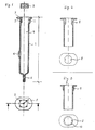
Figur 1 zeigt einen Längsschnitt durch eine erfindungsgemäße 2-Kammer-Spritze mit einer Aufsicht auf das kolbenseitige Ende dieser Spritze;Figur 2 zeigt einen Teil-Längsschnitt durch ein erfindungsgemäßes Spritzenendstück mit angeformten Rippen sowie eine Aufsicht auf das kolbenseitige Ende dieser Spritze;Figur 3 zeigt eine weitere erfindungsgemäße Ausführungsform mit dazugehöriger Aufsicht auf das kolbenseitige Ende der Spritze.
- Figure 1 shows a longitudinal section through a 2-chamber syringe according to the invention with a view of the piston end of this syringe;
- FIG. 2 shows a partial longitudinal section through a syringe end piece according to the invention with integrally formed ribs and a top view of the end of this syringe on the piston side;
- FIG. 3 shows a further embodiment according to the invention with the associated supervision of the end of the syringe on the piston side.
Figur 4 zeigt einen erfindungsgemäßen Spritzenkolben in der Seitenansicht und unmittelbar darunter das kolbenseitige Ende einer üblichen Injektionsspritze, teilweise im Axialschnitt.Figure 4 shows a syringe plunger according to the invention in side view and immediately below the plunger end of a conventional injection syringe, partially in axial section.
Wie in Figur 1 im Schnittbild und in der Aufsicht auf das kolbenseitige Ende einer erfindungsgemäßen LyophilisierSpritze dargestellt, sind in das kolbenseitige Ende des Spritzenzylinders 1 einige Kanäle 2 bzw. Rillen eingelassen, die sowohl zum Innenraum 4 des Spritzenzylinders 1 als auch zur Einfüllöffnung hin offen sind. Diese Kanäle bzw. Rillen verlaufen axial und erstrecken sich ein kleines Stück in Richtung nadelseitiges Ende der Spritze. Sie sind etwa so lang, wie der Spritzenkolben 3 hoch ist, vorzugsweise sind sie ein wenig kürzer als der Kolben 3 hoch ist. Wenn es sich um eine sogenannte 2-Kammer-Spritze handelt, wie in Figur 1 dargestellt, orientiert sich die Länge der Kanäle bzw. Rillen 2 an der Höhe des sogenannten Zwischenkolbens 3, das ist derjenige Kolben, der nach dem Einfüllen der ersten Komponente die erste Kammer von der zweiten Kammer etwas oberhalb des Beipasses 6 trennt. Die Spritze kann ein übliches Nadelansatzstück 5, z.B. einen Luer-Konus aufweisen, der eine übliche Verschlußkappe aufweisen kann und/oder einen Filtereinsatz oder-aufsatz haben kann. Die Spritze kann in einer üblichen Abfüllvorrichtung, bei der das spritzenseitige Ende nach unten hängt, z.B. mit einer Arzneimittellösung beschickt und anschließend mit einem üblichen Kolben 3 versehen werden. Der Kolben 3 wird in diesem Stadium nur so weit in den Spritzenzylinder eingeführt, daß die in die Spritze hineinführenden Enden der Kanäle 2 noch frei liegen, also vom Kolben nicht bedeckt sind. In diesem Zustand, das heißt mit verschlossenem Nadelansatz, eingebrachtem Lyophilisiergut und aufgesetztem Kolben 3,wird die Spritze in die Gefriertrocknungsanlage überführt. Die bei der Gefriertrocknung aus dem Lyophilisiergut abgezogenen Dämpfe entweichen über die Kanäle 2 am Kolben 3 vorbei. Sobald der Gefriertrocknungsprozeß abgeschlossen ist, wird der Kolben 3 so weit in den Spritzenzylinder hineingedrückt, daß die Kanäle 2 verschlossen sind. Wenn die Kanäle 2 etwas kürzer sind als der Kolben 3 hoch ist, wird dieser Verschluß bereits dadurch erreicht, daß der Kolben 3 durch das Zusammenfahren der Stellplatten der Gefriertrocknungsanlage mit dem Spritzenende bündig gedrückt wird. Die Spritze kann in diesem Zustand den Gefriertrockner verlassen. Im Falle einer 2-Kammer-Spritze wird man nach Entnahme aus der Gefriertrocknungsanlage den Zwischenkolben 3 weiter in das Innere der Spritze schieben, bis dicht oberhalb der Stelle, wo der Beipaß 6 endet, sodann wird die zweite Komponente, meist das Lösungsmittel für das Lyophilisat, eingefüllt, und der Injektionskolben eingeführt.As shown in FIG. 1 in the sectional view and in the top view of the plunger-side end of a lyophilizing syringe according to the invention, some
In der in Figur 2 dargestellten Ausführungsform wird die Positionierung und Fixierung des Kolbens 3 und die Entlüftung des Zylinder-Raums 4 dadurch erreicht, daß man am kolbenseitigen Ende kurze Rippen 8 anbringt.In the embodiment shown in Figure 2, the positioning and fixing of the
Diese Rippen 8 können sich entweder über die Zylinderinnenwand 1 erheben, wie in Figur 2 dargestellt oder sie können mit der Zylinderinnenwand fluchten, wie in Figur 3 dargestellt. Bei der in Figur 2 dargestellten Ausführungsform wird der Kolben 3 beim Einsetzen durch die vorspringenden Rippen 8 verformt, dabei legt er sich nicht vollständig an die Rippenseitenwände an und es verbleiben beidseitig von jeder Rippe 8 parallel zur Rippe Luftschlitze, die den Innenraum 4 mit dem umgebenden Raum verbinden so lange der Kolben 3 nicht ganz in das Spritzenende eingeführt worden ist. Der Kolben 3 muß natürlich in seinem Außendurchmesser mindestens dem Innendurchmesser des Spritzenzylinders ohne Rippen entsprechen. Er kann einen kurzen Ansatz geringeren Durchmessers aufweisen, mit dem er leicht in das Spritzenende eingesetzt und zwischen den Rippen 8 positioniert und fixiert werden kann. Durch den Ringspalt zwischen der Außenwand des kurzen Ansatzes und der Innenwand des Spritzenendes können beim Gefriertrocknen die Dämpfe aus der Spritze entweichen.These
Vorteilhafter ist die in Figur 3 gezeigte Ausführungsform, bei der die Rippen 8 eine Fortsetzung der Zylinderinnenwand 1 darstellen und die Zylinderinnenwand im Endbereich 9 erweitert ist, so daß bei eingesetztem Kolben 3 ein Ringraum 10 entsteht, durch den bei der Gefriertrocknung die Dämpfe aus dem Inneren der Spritze entweichen können.The embodiment shown in FIG. 3 is more advantageous, in which the
Für die Abmessungen der Rippen 8 und das Verhältnis der Länge zum Kolben 3 gilt das gleiche, was vorstehend bereits im Zusammenhang mit Figur 1 gesagt wurde. Das gleiche gilt für die Handhabung dieser Ausführungsformen.The same applies to the dimensions of the
Die Zahl der Kanäle 2 oder der Rippen 8 richtet sich nach deren Durchlaßkapazität und der Menge des abzuziehenden Dampfes. Sie wird in der Regel zwischen 3 und 8, vorzugsweise bei 3 bis 5 liegen.
Als Trennkolben zwischen den beiden Kammern einer Zweikammerspritze kann vorteilhaft ein Kolben verwendet werden, der in seiner dem Lyophilisat zugewandten Dichtlippe schräge Durchlässe und zwischen dieser und der darauffolgenden Dichtlippe einen ringförmigen Zwischenraum (zwischen Zylinderinnenwand und Kolbenaußenwand) geringer Tiefe aufweist. Ein derartiger Kolben wirkt als Verteiler für das Lösungsmittel, wenn letzteres bei Betätigung der Spritze im Bereich des Beipasses in den ringförmigen Zwischenraum ein und durch die schrägen Durchlässe in das Lyophilisat austritt.The number of
A piston can advantageously be used as the separating piston between the two chambers of a two-chamber syringe, the piston having oblique passages in its sealing lip facing the lyophilisate and an annular space (between the inner wall of the cylinder and the outer wall of the piston) of shallow depth between this and the subsequent sealing lip. Such a piston acts as a distributor for the solvent when the latter, when the syringe is actuated, enters the annular space in the region of the bypass and exits into the lyophilisate through the oblique passages.
Die in Figur 4 gezeigte Ausführungsform ist besonders vorteilhaft, denn in dieser Ausführungsform kann ein üblicher, unveränderter Spritzenzylinder verwendet werden. Der Spritzenkolben 3 ist in diesem Falle mit einem zylindrischen Ansatz 11 geringeren Durchmessers versehen. Der Durchmesser des Ansatzes ist etwa 10 - 25 % geringer als der Durchmesser des Kolbens im Bereich eines Dichtwulstes und damit natürlich auch geringer als der Innendurchmesser des Spritzenzylinders. Der Kolben 3 wird mit diesem Ansatz 11 im kolbenseitigen Ende des Spritzenzylinders mit Hilfe von noppenartigen Vorsprüngen 12 fixiert, indem man den Kolben nur so weit in das Ende des Spritzenzylinders hineindrückt, daß die noppenartigen Vorsprünge den Innenrand des Spritzenzylinders erfassen. In dieser Stellung gibt es einen Ringspalt zwischen dem Ansatz 11 und der Innenwand des Spritzenzylinders. Durch diesen Ringspalt können beim Lyophilisieren die Dämpfe aus dem Inneren der Spritze entweichen. Der mit einem solchen Ansatz versehene Kolben kann 1 - 3 Dichtwülste aufweisen. Wird er in einer Zweikammer-Spritze verwendet, muß seine dichtende Länge natürlich etwas kürzer sein als der Beipaß in der Spritzenwand. Der in Figur 4 dargestellte Kolben weist außerdem noch axial verlaufende rillenartige Vertiefungen im Umfang des Ansatzes 11 auf, um das Ent- bzw. Belüften des Zylinderinnenraumes bei aufgesetztem Kolben noch zu verbessern.
Auch in diesem Falle darf natürlich der Kolben nicht so weit in das Spritzenende eingeschoben werden, daß der erste Dichtwulst den Ringspalt bzw. die Belüftungskanäle 13 verschließt.The embodiment shown in FIG. 4 is particularly advantageous, because in this embodiment a customary, unchanged syringe barrel can be used. In this case, the
In this case too, of course, the plunger must not be pushed so far into the syringe end that the first sealing bead closes the annular gap or the
Die erfindungsgemäße Spritze bietet wesentliche Vorteile bei der Lyophilisierung gegenüber den bekannten Lyophilisier-Spritzen, die am nadelseitigen Ende offen sind und nach der Lyophilisierung dort durch Einfügen eines Nadelansatzstückes verschlossen werden müssen, was umständliche Operationen im Sterilbereich erfordert. Demgegenüber genugt bei der erfindungsgemäßen Spritze ein leichtes Bündigdrücken des Kolbens 3 mit dem kolbenseitigen Ende der Spritze, um nach Beendigung der Gefriertrocknung die Spritze zu verschließen.The syringe according to the invention offers significant advantages in lyophilization compared to the known lyophilizing syringes, which are open at the needle end and have to be closed there after the lyophilization by inserting a needle attachment piece, which requires laborious operations in the sterile field. In contrast, in the syringe according to the invention, a slight pushing of the
Claims (7)
dadurch gekennzeichnet, daß am Spritzenkolben (3) oder am kolbenseitigen Ende des Spritzenzylinders (1) Mittel vorgesehen sind, die bei eingesetztem aber nicht völlig in den Spritzenzylinder eingeführten Kolben (3) mindestens eine Strömungsverbindung (2,10,13) zwischen Zylinderinnenraum (4) und äußerer Umgebung gewährleisten.1. injection syringe for medical purposes with a syringe barrel having at least one displaceable syringe plunger, which has a needle attachment piece at one end and an opening for inserting the syringe plunger (s) at its end opposite the needle attachment piece,
characterized in that means are provided on the syringe plunger (3) or on the plunger-side end of the syringe barrel (1) which, when the plunger (3) is inserted but not fully inserted into the syringe barrel, has at least one flow connection (2, 10, 13) between the cylinder interior (4 ) and external environment.
dadurch gekennzeichnet, daß es sich bei den Mitteln, welche die Strömungsverbindung (2) gewährleisten um in die Zylinderinnenwand eingelassene zum Zylinderinnenraum (4) und zum Einfüllöffnungsrand (7) hin offene axial verlaufende Kanäle bzw. Rillen (2) oder aber um auf die Zylinderinnenwand aufgesetzte axial verlaufende Rippen (8) handelt.2. hypodermic syringe according to claim 1,
characterized in that the means which ensure the flow connection (2) are axially extending channels or grooves (2) which are let into the cylinder inner wall and open towards the cylinder interior (4) and the filler opening edge (7) or else onto the cylinder inner wall attached axially extending ribs (8).
Priority Applications (1)
| Application Number | Priority Date | Filing Date | Title |
|---|---|---|---|
| AT88110812T ATE68708T1 (en) | 1987-07-21 | 1988-07-06 | INJECTION SYRINGE FOR MEDICAL PURPOSES. |
Applications Claiming Priority (4)
| Application Number | Priority Date | Filing Date | Title |
|---|---|---|---|
| DE3724120 | 1987-07-21 | ||
| DE3724120 | 1987-07-21 | ||
| DE3816961 | 1988-05-18 | ||
| DE3816961A DE3816961A1 (en) | 1987-07-21 | 1988-05-18 | INJECTION SYRINGE FOR MEDICAL PURPOSES |
Publications (3)
| Publication Number | Publication Date |
|---|---|
| EP0302248A1 true EP0302248A1 (en) | 1989-02-08 |
| EP0302248B1 EP0302248B1 (en) | 1991-10-23 |
| EP0302248B2 EP0302248B2 (en) | 1996-01-10 |
Family
ID=25857794
Family Applications (1)
| Application Number | Title | Priority Date | Filing Date |
|---|---|---|---|
| EP88110812A Expired - Lifetime EP0302248B2 (en) | 1987-07-21 | 1988-07-06 | Injection syringe for medical purposes |
Country Status (4)
| Country | Link |
|---|---|
| US (1) | US4952208A (en) |
| EP (1) | EP0302248B2 (en) |
| AT (1) | ATE68708T1 (en) |
| DE (2) | DE3816961A1 (en) |
Cited By (14)
| Publication number | Priority date | Publication date | Assignee | Title |
|---|---|---|---|---|
| WO1992001485A1 (en) * | 1990-07-20 | 1992-02-06 | Novo Nordisk A/S | Two compartment syringe |
| WO1993021986A2 (en) * | 1992-04-28 | 1993-11-11 | Schering-Plough Healthcare Products, Inc. | Applicator for semisolid medications |
| EP0599649A1 (en) * | 1992-11-27 | 1994-06-01 | Daikyo Seiko, Ltd. | A combined syringe-container |
| EP0664137A2 (en) * | 1994-01-25 | 1995-07-26 | Becton, Dickinson and Company | Syringe and method for lyophilizing and reconstituting injectable medication |
| WO1996030066A1 (en) * | 1995-03-29 | 1996-10-03 | Abbott Laboratories | Syringe barrel for lyophilization, reconstitution and administration |
| US5785682A (en) * | 1995-03-22 | 1998-07-28 | Abbott Laboratories | Pre-filled syringe drug delivery system |
| US5876372A (en) * | 1995-03-22 | 1999-03-02 | Abbott Laboratories | Syringe system accomodating seperate prefilled barrels for two constituents |
| EP1651114A1 (en) * | 2003-08-07 | 2006-05-03 | FRASS, Michael | Device used for needle biopsy |
| EP1911478A1 (en) * | 2006-10-09 | 2008-04-16 | E-Z-EM, Inc. | Syringe device and injector system including a vent for relieving a vacuum within a syringe |
| US8613730B2 (en) | 2008-11-26 | 2013-12-24 | Acist Medical Systems, Inc. | Apparatus and methods for fluid pressurizing units of injection systems |
| EP2739332A2 (en) * | 2011-08-01 | 2014-06-11 | Synchrojet LLC | Stopper/plunger for carpules of syringe-carpule assembly |
| WO2020169921A1 (en) | 2019-02-21 | 2020-08-27 | Lyofal | Container for packaging materials under a controlled atmosphere, and packaging process using such a container |
| US11033678B2 (en) | 2017-11-20 | 2021-06-15 | Agist Medical Systems, Inc. | Compact injector drive |
| US11040147B2 (en) | 2017-11-21 | 2021-06-22 | Acist Medical Systems, Inc. | Injector position sensing |
Families Citing this family (13)
| Publication number | Priority date | Publication date | Assignee | Title |
|---|---|---|---|---|
| US5135507A (en) * | 1990-05-10 | 1992-08-04 | Habley Medical Technology Corporation | One-piece syringe |
| US5350367A (en) * | 1990-11-06 | 1994-09-27 | Sterling Winthrop Inc. | Snap together hypodermic syringe holder |
| US5489266A (en) * | 1994-01-25 | 1996-02-06 | Becton, Dickinson And Company | Syringe assembly and method for lyophilizing and reconstituting injectable medication |
| DE4445969C1 (en) * | 1994-12-22 | 1996-03-14 | Schott Glaswerke | Syringe cylinder with two compartments for two constituents |
| US5685846A (en) * | 1995-02-27 | 1997-11-11 | Schott Parenta Systems, Inc. | Dual chamber internal by-pass syringe assembly |
| JPH11155951A (en) * | 1997-12-01 | 1999-06-15 | Kaken Pharmaceut Co Ltd | Decompression syringe and manufacture thereof |
| US6907679B2 (en) * | 1998-11-12 | 2005-06-21 | Qlt Usa, Inc. | Method for lyophilizing an active agent |
| US20090105660A1 (en) * | 2006-02-28 | 2009-04-23 | Hisamitsu Pharmaceutical Co., Inc. | Syringe Cylinder |
| ES2386166T5 (en) † | 2007-06-14 | 2016-06-21 | Sanofi-Aventis Deutschland Gmbh | Two-chamber carpule with accessory |
| US9623184B2 (en) * | 2009-12-04 | 2017-04-18 | Becton, Dickinson And Company | Cartridge for containing and dispensing a medicament |
| US20150051576A1 (en) * | 2012-03-30 | 2015-02-19 | Koninklijke Philips N.V. | Nested cannula tips |
| WO2017136667A1 (en) | 2016-02-05 | 2017-08-10 | Tolmar Tharapeutics, Inc. | Vented cover plate for an array of syringes |
| USD908916S1 (en) | 2018-06-19 | 2021-01-26 | Tolmar Therapeutics, Inc. | Syringe restrictor plate |
Citations (6)
| Publication number | Priority date | Publication date | Assignee | Title |
|---|---|---|---|---|
| US3737973A (en) * | 1970-10-20 | 1973-06-12 | Becton Dickinson Co | Method and device for assembling a stopper to a syringe barrel |
| US4266557A (en) * | 1978-01-16 | 1981-05-12 | The Kendall Company | Low friction syringe |
| DE3339705A1 (en) | 1983-11-03 | 1985-05-15 | Arzneimittel Gmbh Apotheker Vetter & Co Ravensburg, 7980 Ravensburg | Syringe for medical purposes |
| EP0144483A2 (en) | 1983-12-09 | 1985-06-19 | Arzneimittel GmbH Apotheker Vetter & Co. Ravensburg | Syringe for medical applications |
| EP0144551A1 (en) * | 1983-09-28 | 1985-06-19 | Becton Dickinson and Company | Two-component medication syringe assembly |
| EP0191122A1 (en) | 1983-11-03 | 1986-08-20 | Arzneimittel GmbH Apotheker Vetter & Co. Ravensburg | Syringe for medical applications |
Family Cites Families (9)
| Publication number | Priority date | Publication date | Assignee | Title |
|---|---|---|---|---|
| US2591046A (en) * | 1948-10-18 | 1952-04-01 | Frederick M Turnbull | Hypodermic syringe assembly |
| US2717601A (en) * | 1949-08-10 | 1955-09-13 | Frederick M Turnbull | Syringe ampule |
| CH419458A (en) * | 1964-02-29 | 1966-08-31 | Hartmann Paul Ag | Injection syringe |
| US3255752A (en) * | 1965-01-28 | 1966-06-14 | Dick Peter | Hypodermic syringe |
| DK112893B (en) * | 1966-07-25 | 1969-01-27 | Bay Schmith N | Mixing syringe for use in mixing predetermined amounts of liquids and solids. |
| EP0072058A1 (en) * | 1981-08-10 | 1983-02-16 | Duphar International Research B.V | Multiple-compartment syringe |
| US4540410A (en) * | 1982-11-16 | 1985-09-10 | Serono Pharmaceutical Partners | Lyophilized compositions, preparation and use thereof |
| US4599082A (en) * | 1984-08-13 | 1986-07-08 | Becton, Dickinson And Company | Two-component syringe assembly |
| US4690154A (en) * | 1985-06-03 | 1987-09-01 | Timothy Woodford | Vented syringe |
-
1988
- 1988-05-18 DE DE3816961A patent/DE3816961A1/en not_active Withdrawn
- 1988-07-06 EP EP88110812A patent/EP0302248B2/en not_active Expired - Lifetime
- 1988-07-06 DE DE8888110812T patent/DE3865770D1/en not_active Expired - Fee Related
- 1988-07-06 AT AT88110812T patent/ATE68708T1/en not_active IP Right Cessation
- 1988-07-22 US US07/227,185 patent/US4952208A/en not_active Expired - Fee Related
Patent Citations (6)
| Publication number | Priority date | Publication date | Assignee | Title |
|---|---|---|---|---|
| US3737973A (en) * | 1970-10-20 | 1973-06-12 | Becton Dickinson Co | Method and device for assembling a stopper to a syringe barrel |
| US4266557A (en) * | 1978-01-16 | 1981-05-12 | The Kendall Company | Low friction syringe |
| EP0144551A1 (en) * | 1983-09-28 | 1985-06-19 | Becton Dickinson and Company | Two-component medication syringe assembly |
| DE3339705A1 (en) | 1983-11-03 | 1985-05-15 | Arzneimittel Gmbh Apotheker Vetter & Co Ravensburg, 7980 Ravensburg | Syringe for medical purposes |
| EP0191122A1 (en) | 1983-11-03 | 1986-08-20 | Arzneimittel GmbH Apotheker Vetter & Co. Ravensburg | Syringe for medical applications |
| EP0144483A2 (en) | 1983-12-09 | 1985-06-19 | Arzneimittel GmbH Apotheker Vetter & Co. Ravensburg | Syringe for medical applications |
Cited By (29)
| Publication number | Priority date | Publication date | Assignee | Title |
|---|---|---|---|---|
| WO1992001485A1 (en) * | 1990-07-20 | 1992-02-06 | Novo Nordisk A/S | Two compartment syringe |
| US5531703A (en) * | 1992-04-28 | 1996-07-02 | Schering-Plough Healthcare Products, Inc. | Applicator for semisolid medications |
| WO1993021986A2 (en) * | 1992-04-28 | 1993-11-11 | Schering-Plough Healthcare Products, Inc. | Applicator for semisolid medications |
| WO1993021986A3 (en) * | 1992-04-28 | 1994-01-06 | Schering Plough Healthcare | Applicator for semisolid medications |
| EP0599649A1 (en) * | 1992-11-27 | 1994-06-01 | Daikyo Seiko, Ltd. | A combined syringe-container |
| US5637100A (en) * | 1992-11-27 | 1997-06-10 | Daikyo Seiko, Ltd. | Syringe-cum-container |
| EP0664137A3 (en) * | 1994-01-25 | 1995-08-30 | Becton Dickinson Co | |
| EP0664137A2 (en) * | 1994-01-25 | 1995-07-26 | Becton, Dickinson and Company | Syringe and method for lyophilizing and reconstituting injectable medication |
| US5752940A (en) * | 1994-01-25 | 1998-05-19 | Becton Dickinson And Company | Syringe and method for lyophilizing and reconstituting injectable medication |
| US5785682A (en) * | 1995-03-22 | 1998-07-28 | Abbott Laboratories | Pre-filled syringe drug delivery system |
| US5876372A (en) * | 1995-03-22 | 1999-03-02 | Abbott Laboratories | Syringe system accomodating seperate prefilled barrels for two constituents |
| WO1996030066A1 (en) * | 1995-03-29 | 1996-10-03 | Abbott Laboratories | Syringe barrel for lyophilization, reconstitution and administration |
| US5779668A (en) * | 1995-03-29 | 1998-07-14 | Abbott Laboratories | Syringe barrel for lyophilization, reconstitution and administration |
| EP1651114A1 (en) * | 2003-08-07 | 2006-05-03 | FRASS, Michael | Device used for needle biopsy |
| EP1911478A1 (en) * | 2006-10-09 | 2008-04-16 | E-Z-EM, Inc. | Syringe device and injector system including a vent for relieving a vacuum within a syringe |
| WO2008045876A2 (en) * | 2006-10-09 | 2008-04-17 | Acist Medical Systems, Inc. | Syringe device and injector system including a vent for relieving a vacuum within a syringe |
| WO2008045876A3 (en) * | 2006-10-09 | 2008-06-05 | E Z Em Inc | Syringe device and injector system including a vent for relieving a vacuum within a syringe |
| CN101161303B (en) * | 2006-10-09 | 2012-07-04 | 阿西斯特医疗系统公司 | Syringe device and injector system including a vent for relieving a vacuum within a syringe |
| US8540683B2 (en) | 2006-10-09 | 2013-09-24 | Acist Medical Systems, Inc. | Syringe device and injector system including a vent for relieving a vacuum within a syringe |
| US8613730B2 (en) | 2008-11-26 | 2013-12-24 | Acist Medical Systems, Inc. | Apparatus and methods for fluid pressurizing units of injection systems |
| US9925338B2 (en) | 2008-11-26 | 2018-03-27 | Acist Medical Systems, Inc. | Apparatus and methods for fluid pressurizing units of injection systems |
| EP2739332A4 (en) * | 2011-08-01 | 2015-04-01 | Synchrojet Llc | Stopper/plunger for carpules of syringe-carpule assembly |
| US9022995B2 (en) | 2011-08-01 | 2015-05-05 | Synchrojet Llc | Stopper/plunger for carpules of syringe-carpule assembly |
| EP2739332A2 (en) * | 2011-08-01 | 2014-06-11 | Synchrojet LLC | Stopper/plunger for carpules of syringe-carpule assembly |
| US11033678B2 (en) | 2017-11-20 | 2021-06-15 | Agist Medical Systems, Inc. | Compact injector drive |
| US11730885B2 (en) | 2017-11-20 | 2023-08-22 | Acist Medical Systems, Inc. | Compact injector drive |
| US11040147B2 (en) | 2017-11-21 | 2021-06-22 | Acist Medical Systems, Inc. | Injector position sensing |
| WO2020169921A1 (en) | 2019-02-21 | 2020-08-27 | Lyofal | Container for packaging materials under a controlled atmosphere, and packaging process using such a container |
| FR3093088A1 (en) | 2019-02-21 | 2020-08-28 | Lyofal | Container for packaging materials in a controlled atmosphere and method of packaging using such a container |
Also Published As
| Publication number | Publication date |
|---|---|
| DE3865770D1 (en) | 1991-11-28 |
| EP0302248B2 (en) | 1996-01-10 |
| EP0302248B1 (en) | 1991-10-23 |
| US4952208A (en) | 1990-08-28 |
| ATE68708T1 (en) | 1991-11-15 |
| DE3816961A1 (en) | 1989-02-02 |
Similar Documents
| Publication | Publication Date | Title |
|---|---|---|
| EP0302248B1 (en) | Injection syringe for medical purposes | |
| EP0328699B1 (en) | Syringe for medical use | |
| WO2007020239A1 (en) | Twin-chamber receptacle and method for filling the same | |
| WO2007020240A1 (en) | Twin-chamber lyophilization receptacle, method for filling the same, and use thereof | |
| EP0718002B1 (en) | Two compartment syringe and process for manufacture and filling thereof | |
| DE69725220T2 (en) | Piston device with bypass for use in the cylinder of a multi-chamber syringe | |
| EP0397977B1 (en) | Syringe for medical use | |
| EP0652019B1 (en) | Mixing and administration syringe | |
| EP1038543B1 (en) | Syringe for medical purposes | |
| DE60113410T2 (en) | SYRINGE SYSTEMS FOR LYOPHILIZED MEDICAMENTS AND METHOD FOR THE PRODUCTION THEREOF | |
| EP0399234B1 (en) | Ampoule | |
| EP0922499B1 (en) | Fluid dispenser | |
| DE69433044T2 (en) | Production of an injection cartridge | |
| DE69927170T2 (en) | DEVICE FOR STORING, MIXING AND DISPENSING A MEDICAMENT | |
| EP2680909A1 (en) | Closure and method for producing a closure | |
| EP0193054A1 (en) | Dispensing device for flowable matter | |
| DE2909002B2 (en) | Single use syringe | |
| EP0412283A1 (en) | Syringe cylinder for medical use | |
| WO2002092312A1 (en) | Pharmaceutical syringe piston and method and device therefor | |
| DE2046953A1 (en) | Syringe filled through the closure opening and method of filling it | |
| DE1296312B (en) | Two-chamber container for the separate filling and storage of drugs and solutions or diluents in a form suitable for later mixing and subsequent removal | |
| DE69723278T2 (en) | PHARMACEUTICAL AMPOULE | |
| DE3736343C2 (en) | Hypodermic syringe | |
| DE60029623T2 (en) | UNIT FOR MICROBIOLOGICAL TESTING OF A LIQUID SAMPLE UNDER PRESSURE AND PROCEDURE FOR EMPTYING THIS UNIT | |
| DE102011013791A1 (en) | Closure for syringe or carpule, has sealing element which is sealingly provided at opening of syringe or carpule when closure is set in closing position, where closure is formed as single-piece component |
Legal Events
| Date | Code | Title | Description |
|---|---|---|---|
| PUAI | Public reference made under article 153(3) epc to a published international application that has entered the european phase |
Free format text: ORIGINAL CODE: 0009012 |
|
| AK | Designated contracting states |
Kind code of ref document: A1 Designated state(s): AT BE CH DE ES FR GB GR IT LI LU NL SE |
|
| RBV | Designated contracting states (corrected) |
Designated state(s): AT BE CH DE FR GB IT LI NL |
|
| 17P | Request for examination filed |
Effective date: 19890622 |
|
| 17Q | First examination report despatched |
Effective date: 19901207 |
|
| GRAA | (expected) grant |
Free format text: ORIGINAL CODE: 0009210 |
|
| AK | Designated contracting states |
Kind code of ref document: B1 Designated state(s): AT BE CH DE FR GB IT LI NL |
|
| PG25 | Lapsed in a contracting state [announced via postgrant information from national office to epo] |
Ref country code: IT Free format text: LAPSE BECAUSE OF FAILURE TO SUBMIT A TRANSLATION OF THE DESCRIPTION OR TO PAY THE FEE WITHIN THE PRESCRIBED TIME-LIMIT;WARNING: LAPSES OF ITALIAN PATENTS WITH EFFECTIVE DATE BEFORE 2007 MAY HAVE OCCURRED AT ANY TIME BEFORE 2007. THE CORRECT EFFECTIVE DATE MAY BE DIFFERENT FROM THE ONE RECORDED. Effective date: 19911023 Ref country code: FR Effective date: 19911023 Ref country code: BE Effective date: 19911023 Ref country code: GB Effective date: 19911023 Ref country code: NL Effective date: 19911023 |
|
| REF | Corresponds to: |
Ref document number: 68708 Country of ref document: AT Date of ref document: 19911115 Kind code of ref document: T |
|
| REF | Corresponds to: |
Ref document number: 3865770 Country of ref document: DE Date of ref document: 19911128 |
|
| EN | Fr: translation not filed | ||
| NLV1 | Nl: lapsed or annulled due to failure to fulfill the requirements of art. 29p and 29m of the patents act | ||
| GBV | Gb: ep patent (uk) treated as always having been void in accordance with gb section 77(7)/1977 [no translation filed] | ||
| PLBI | Opposition filed |
Free format text: ORIGINAL CODE: 0009260 |
|
| 26 | Opposition filed |
Opponent name: ARZNEIMITTEL GMBH APOTHEKER VETTER & CO. Effective date: 19920718 |
|
| PUAH | Patent maintained in amended form |
Free format text: ORIGINAL CODE: 0009272 |
|
| STAA | Information on the status of an ep patent application or granted ep patent |
Free format text: STATUS: PATENT MAINTAINED AS AMENDED |
|
| 27A | Patent maintained in amended form |
Effective date: 19960110 |
|
| AK | Designated contracting states |
Kind code of ref document: B2 Designated state(s): AT BE CH DE FR GB IT LI NL |
|
| REG | Reference to a national code |
Ref country code: CH Ref legal event code: AEN Free format text: AUFRECHTERHALTUNG DES PATENTES IN GEAENDERTER FORM |
|
| EN | Fr: translation not filed | ||
| PGFP | Annual fee paid to national office [announced via postgrant information from national office to epo] |
Ref country code: CH Payment date: 19980708 Year of fee payment: 11 |
|
| PGFP | Annual fee paid to national office [announced via postgrant information from national office to epo] |
Ref country code: DE Payment date: 19980925 Year of fee payment: 11 |
|
| PG25 | Lapsed in a contracting state [announced via postgrant information from national office to epo] |
Ref country code: LI Free format text: LAPSE BECAUSE OF NON-PAYMENT OF DUE FEES Effective date: 19990731 Ref country code: CH Free format text: LAPSE BECAUSE OF NON-PAYMENT OF DUE FEES Effective date: 19990731 |
|
| PGFP | Annual fee paid to national office [announced via postgrant information from national office to epo] |
Ref country code: AT Payment date: 19990731 Year of fee payment: 12 |
|
| REG | Reference to a national code |
Ref country code: CH Ref legal event code: PL |
|
| PG25 | Lapsed in a contracting state [announced via postgrant information from national office to epo] |
Ref country code: DE Free format text: LAPSE BECAUSE OF NON-PAYMENT OF DUE FEES Effective date: 20000503 |
|
| PG25 | Lapsed in a contracting state [announced via postgrant information from national office to epo] |
Ref country code: AT Free format text: LAPSE BECAUSE OF NON-PAYMENT OF DUE FEES Effective date: 20000706 |