EP0300902A1 - Spraying installation and pneumatic spray gun for a coating product - Google Patents
Spraying installation and pneumatic spray gun for a coating product Download PDFInfo
- Publication number
- EP0300902A1 EP0300902A1 EP88401881A EP88401881A EP0300902A1 EP 0300902 A1 EP0300902 A1 EP 0300902A1 EP 88401881 A EP88401881 A EP 88401881A EP 88401881 A EP88401881 A EP 88401881A EP 0300902 A1 EP0300902 A1 EP 0300902A1
- Authority
- EP
- European Patent Office
- Prior art keywords
- trigger
- components
- installation according
- coating product
- air flow
- Prior art date
- Legal status (The legal status is an assumption and is not a legal conclusion. Google has not performed a legal analysis and makes no representation as to the accuracy of the status listed.)
- Granted
Links
Images

Classifications
-
- B—PERFORMING OPERATIONS; TRANSPORTING
- B05—SPRAYING OR ATOMISING IN GENERAL; APPLYING FLUENT MATERIALS TO SURFACES, IN GENERAL
- B05B—SPRAYING APPARATUS; ATOMISING APPARATUS; NOZZLES
- B05B12/00—Arrangements for controlling delivery; Arrangements for controlling the spray area
- B05B12/14—Arrangements for controlling delivery; Arrangements for controlling the spray area for supplying a selected one of a plurality of liquids or other fluent materials or several in selected proportions to a spray apparatus, e.g. to a single spray outlet
- B05B12/1418—Arrangements for controlling delivery; Arrangements for controlling the spray area for supplying a selected one of a plurality of liquids or other fluent materials or several in selected proportions to a spray apparatus, e.g. to a single spray outlet for supplying several liquids or other fluent materials in selected proportions to a single spray outlet
-
- B—PERFORMING OPERATIONS; TRANSPORTING
- B05—SPRAYING OR ATOMISING IN GENERAL; APPLYING FLUENT MATERIALS TO SURFACES, IN GENERAL
- B05B—SPRAYING APPARATUS; ATOMISING APPARATUS; NOZZLES
- B05B12/00—Arrangements for controlling delivery; Arrangements for controlling the spray area
- B05B12/002—Manually-actuated controlling means, e.g. push buttons, levers or triggers
-
- B—PERFORMING OPERATIONS; TRANSPORTING
- B05—SPRAYING OR ATOMISING IN GENERAL; APPLYING FLUENT MATERIALS TO SURFACES, IN GENERAL
- B05B—SPRAYING APPARATUS; ATOMISING APPARATUS; NOZZLES
- B05B12/00—Arrangements for controlling delivery; Arrangements for controlling the spray area
- B05B12/08—Arrangements for controlling delivery; Arrangements for controlling the spray area responsive to condition of liquid or other fluent material to be discharged, of ambient medium or of target ; responsive to condition of spray devices or of supply means, e.g. pipes, pumps or their drive means
-
- B—PERFORMING OPERATIONS; TRANSPORTING
- B05—SPRAYING OR ATOMISING IN GENERAL; APPLYING FLUENT MATERIALS TO SURFACES, IN GENERAL
- B05B—SPRAYING APPARATUS; ATOMISING APPARATUS; NOZZLES
- B05B7/00—Spraying apparatus for discharge of liquids or other fluent materials from two or more sources, e.g. of liquid and air, of powder and gas
- B05B7/02—Spray pistols; Apparatus for discharge
- B05B7/12—Spray pistols; Apparatus for discharge designed to control volume of flow, e.g. with adjustable passages
- B05B7/1254—Spray pistols; Apparatus for discharge designed to control volume of flow, e.g. with adjustable passages the controlling means being fluid actuated
- B05B7/1263—Spray pistols; Apparatus for discharge designed to control volume of flow, e.g. with adjustable passages the controlling means being fluid actuated pneumatically actuated
- B05B7/1272—Spray pistols; Apparatus for discharge designed to control volume of flow, e.g. with adjustable passages the controlling means being fluid actuated pneumatically actuated actuated by gas involved in spraying, i.e. exiting the nozzle, e.g. as a spraying or jet shaping gas
- B05B7/1281—Serial arrangement, i.e. a single gas stream acting on the controlling means first and flowing downstream thereof to the nozzle
-
- B—PERFORMING OPERATIONS; TRANSPORTING
- B05—SPRAYING OR ATOMISING IN GENERAL; APPLYING FLUENT MATERIALS TO SURFACES, IN GENERAL
- B05B—SPRAYING APPARATUS; ATOMISING APPARATUS; NOZZLES
- B05B7/00—Spraying apparatus for discharge of liquids or other fluent materials from two or more sources, e.g. of liquid and air, of powder and gas
- B05B7/24—Spraying apparatus for discharge of liquids or other fluent materials from two or more sources, e.g. of liquid and air, of powder and gas with means, e.g. a container, for supplying liquid or other fluent material to a discharge device
- B05B7/26—Apparatus in which liquids or other fluent materials from different sources are brought together before entering the discharge device
- B05B7/28—Apparatus in which liquids or other fluent materials from different sources are brought together before entering the discharge device in which one liquid or other fluent material is fed or drawn through an orifice into a stream of a carrying fluid
- B05B7/32—Apparatus in which liquids or other fluent materials from different sources are brought together before entering the discharge device in which one liquid or other fluent material is fed or drawn through an orifice into a stream of a carrying fluid the fed liquid or other fluent material being under pressure
Definitions
- the invention relates to an installation for spraying coating product with manual control, that is to say using a pneumatic sprayer with manual control, provided with an actuating trigger controlling both the flow of coating product (paint) and the opening of the valve controlling the supply of spray air for this product.
- the invention relates more particularly to improvements allowing better control of the air flows and of coating product. It finds a preferred application in installations using two-component paints or varnishes (typically a base and a hardener) in order to better control, in all circumstances, the volumetric ratio between these two components.
- two-component paints or varnishes typically a base and a hardener
- a conventional manual spray paint installation comprises at least one pneumatic sprayer provided with an actuating trigger and connected, on the one hand, to a paint supply duct and, on the other hand, to a duct compressed air supply.
- the paint is atomized and propelled by air towards the object to be painted.
- the user controls the spray of sprayed paint by pressing the trigger more or less.
- the paint passes through a valve controlled by the trigger.
- the actuation of this valve is proportional, that is to say that its arrangement is such that the flow rate of the valve is a function of the degree of depression of the trigger.
- the air inlet control valve also controlled by the trigger, is of the "all or nothing" type, that is to say that the air flow remains practically constant whatever the flow paint.
- the invention therefore essentially relates to a coating product spraying installation comprising at least one pneumatic sprayer with manual control, provided with an actuating trigger, connected to means for supplying product to be sprayed and to a source of compressed air, characterized in that said headlight comprises a means for progressive adjustment of the air flow rate, sensitive to the position of said actuating trigger.
- the invention relates to another improvement making it possible to control the paint flow more precisely, by means of a gear pump inserted in the paint supply circuit.
- the invention therefore also relates to an installation according to the above definition, characterized in that said means for supplying coating product comprise a gear pump driven by a variable speed motor, controlled by sensitive control means. , in particular, to an electrical signal representative of the position of said trigger.
- the installation in question will include a sensor for the spraying air flow rate and this sensor will be part of the means for generating the electrical signal representative of the position of the trigger.
- the invention therefore also relates to an installation in accordance with the preceding description and comprising a mixer of said components, inserted upstream of the projector and comprising two inputs, respectively for the two components and an output connected to said projector, characterized in that that gear pumps are respectively inserted in respective supply circuits of said components, upstream of said mixer and in that these pumps are respectively driven by variable speed motors, controlled by control means able to maintain the flow rates of said components in a predetermined ratio.
- a manually operated paint sprayer 10 conventionally comprising, a spray nozzle 11, a connection nozzle 12 connected to a paint supply conduit 12 a and a nozzle connection 14 connected to a compressed air supply duct 14 a .
- An actuating trigger 16 is articulated at 17 to the body of the projector. It is coupled to the needle of a proportional action valve (not shown) controlling the paint flow and, according to a an important characteristic of the invention, it is also coupled, by an articulated rod 19, to a means of progressive adjustment of the air flow.
- a flow control valve 21 comprising a shutter element 22 movable relative to a seat 23 defined in a chamber 24 between an inlet 25 connected to the nozzle 14 and a outlet 26 connected to the spraying means.
- the rod 19 is attached to the closure element 22 while a spring 28, located in the chamber 24, biases said closure element towards the seat 23, that is to say towards the closed position of valve.
- the progressive adjustment of the air flow, sensitive to the position of the trigger, is obtained by rolling the air over a certain variable axial distance, in an annular passage 30 defined between the closure element and the seat.
- the closure element comprises a substantially cylindrical core 22 a and the seat 23 comprises or is extended by a portion of conduit 23 a substantially cylindrical and of diameter greater than that of the core 22 a .
- the annular passage 30, of variable length, is defined between said core 22 a and said portion of conduit 23 a .
- This core, under the action of the rod 19 and the spring 28 is axially movable inside said portion of conduit.
- the length d thereof corresponds substantially to the stroke of the trigger.
- the pressure drop caused by the rolling of the air in the passage 30 and, consequently, the flow of atomizing air depend on the position of the trigger.
- the air flow and the paint flow vary with the position of said trigger.
- there will be a low air consumption avoiding drying the paint by an excess of air.
- FIG. 2 illustrates, in its simplest form, a coating product spraying installation using the projector of FIG. 1.
- the air supply means connected to the nozzle 14, comprise an air flow sensor 34 for measuring the spraying air flow rate determined by the valve 21.
- this sensor of any known type, is inserted between a source of compressed air, represented here by the conduit 36 and the projector 10. The sensor could of course be integrated into said projector.
- This sensor delivers at its output 34 to an electrical signal representative of the air flow and thus consequently the depression of the trigger.
- the coating material supply means comprise a gear pump 38 driven by a variable speed motor 39.
- This pump is here inserted between a paint circulation duct 40 and the nozzle 12.
- the motor 39 is supplied by control means 42 (for example a current amplifier) sensitive, in particular to an electrical signal representative of the position of the trigger 16. In the example described, this signal is precisely delivered by the electrical output 34 a of the sensor air flow 34.
- opto-electric means are used to develop the signal representative of the position of the trigger 16.
- the latter is mechanically linked to a reflecting element 44 pivotally mounted and this reflecting element is inserted into a circuit of optical fibers 45, 46 established between a light source 47 and an optoelectric sensor 48.
- the latter is part of the means for developing the electrical signal representative of the position of the trigger.
- the electrical signal output of the sensor 48 can be connected to the control means 42 in the same way as the output 34 a of the air flow sensor 34.
- FIG. 2 is preferable because it has the additional advantage of making the pump also sensitive to possible fluctuations in the air pressure.
- the paint flow rate can thus be automatically modified to maintain a substantially constant air-paint dosage. This avoids any excess paint and therefore, any risk of leakage.
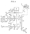
- FIG. 4 illustrates a particularly advantageous application of the invention, for the implementation of a two-component coating product, in particular a paint formed by the mixture of a colored base and a hardener.
- a mixer 50 inserted upstream from the projector 10.
- This mixer has two inputs 50 a , 50 b , for each of the two components at an output 51 connected to the connection end piece 12.
- the mixer is also connected, by a non-return valve 52, to a cleaning block 53, known per se, comprising an inlet for solvent 53 a and an inlet for compressed air 53 b .
- a paint supply circuit (or base) 55 and a hardener supply circuit 56 there is a paint supply circuit (or base) 55 and a hardener supply circuit 56.
- the output of circuit 55 is connected to input 50 a of the mixer, and the output of circuit 56 is connected to input 50 b of the mixer.
- the circuit 55 is connected to a color changing block 60, known per se, itself connected to several paint supply pipes or bases of different colors 61-63, to an air supply pipe 65 and to a solvent supply pipe 66.
- the circuit 55 thus successively comprises, between the color changing block 60 and the mixer, a gear pump 67 a driven by a variable speed electric motor 68 a , a flow sensor 69 a and a purge valve 70 a .
- a safety valve 71a is connected in parallel to the pump.
- the flow sensor 69 a is here advantageously of the "gear" type, that is to say that its mechanical part is very structurally similar to a gear pump.
- One of the pinions of this gear sensor is coupled to an inductive transducer 72 a whose electrical output delivers a signal representative of the flow of liquid in the circuit 55.
- the hardener circulation circuit 56 is quite comparable to the circuit 55 It is connected to a hardener circulation duct 78 and comprises, interconnected in the same way, a gear pump 67 b , driven by a motor 68 b , a flow sensor 69 b with its transducer 72 b , a valve safety 71 b and a purge valve 70 b .
- the compressed air supply means are similar to those of FIG. 2 and therefore comprise an air flow sensor 73 connected between the conduit 65 and the connection end piece 14.
- a computer 75 receives the output signals from the flow sensors 69 a and 69 b and from the air flow sensor 73 (delivering a signal representative of the position of the trigger) and delivers signals control with two current amplifiers 76 a , 76 b respectively supplying the motors 68 a , 68 b .
- the computer 75 is part of the engine control means 68 a , 68 b . It is programmed to maintain the flow rates of the two components flowing in the circuits 55 and 56, in a predetermined ratio.
- the system When the trigger is pulled very lightly, the system is set so that a low flow of spray air occurs before paint is admitted to the projector.
- the paint inlet valve control needle is then still closed.
- the pump is only allowed to operate from a certain level of air flow for which it is certain that the valve needle is actually open. All of these operating details can easily be taken into account by the computer 75.
- a minimum flow threshold is fixed below which the pump is stopped. The thresholds can be different on opening and closing. We can also anticipate the pump stopping before closing the needle, if the air flow sensor has a relatively slow response.
Abstract
Description
L'invention se rapporte à une installation de pulvérisation de produit de revêtement à commande manuelle, c'est-à-dire mettant en oeuvre un projecteur pneumatique à commande manuelle, muni d'une gâchette d'actionnement commandant à la fois le débit de produit de revêtement (peinture) et l'ouverture de la vanne commandant l'arrivée d'air de pulvérisation de ce produit.The invention relates to an installation for spraying coating product with manual control, that is to say using a pneumatic sprayer with manual control, provided with an actuating trigger controlling both the flow of coating product (paint) and the opening of the valve controlling the supply of spray air for this product.
L'invention vise plus particulièrement des perfectionnements permettant de mieux maîtriser les débits d'air et de produit de revêtement. Elle trouve une application privilégiée dans les installations mettant en oeuvre les peintures ou vernis à deux composants (typiquement une base et un durcisseur) afin de mieux maîtriser, en toutes circonstances, le rapport volumétrique entre ces deux composants.The invention relates more particularly to improvements allowing better control of the air flows and of coating product. It finds a preferred application in installations using two-component paints or varnishes (typically a base and a hardener) in order to better control, in all circumstances, the volumetric ratio between these two components.
Une installation classique de pulvérisation de peinture à commande manuelle comporte au moins un projecteur pneumatique muni d'une gâchette d'actionnement et raccordé, d'une part, à un conduit d'alimentation de peinture et, d'autre part, à un conduit d'alimentation en air comprimé. La peinture est atomisée et propulsée par l'air vers l'objet à peindre. L'utilisateur contrôle le jet de peinture pulvérisée en appuyant plus ou moins sur la gâchette. La peinture traverse une vanne commandée par la gâchette. L'actionnement de cette vanne est proportionnel, c'est-à-dire que son agencement est tel que le débit de la vanne soit fonction du degré d'enfoncement de la gâchette. En revanche, la vanne de commande d'arrivée d'air, également commandée par la gâchette, est du type "tout ou rien", c'est-à-dire que le débit d'air reste pratiquement constant quel que soit le débit de peinture. On a constaté que cette particularité de structure des projecteurs connus, pouvait être en soi préjudiciable à une bonne pulvérisation. En effet, il peut être néfaste d'utiliser trop d'air pour un débit de peinture comparativement faible. On a constaté qu'un excès d'air a tendance à assécher la peinture avant qu'elle n'atteigne l'objet à peindre, ce qui peut entraîner un défaut d'aspect. L'un des buts de l'invention est de résoudre ce problème.A conventional manual spray paint installation comprises at least one pneumatic sprayer provided with an actuating trigger and connected, on the one hand, to a paint supply duct and, on the other hand, to a duct compressed air supply. The paint is atomized and propelled by air towards the object to be painted. The user controls the spray of sprayed paint by pressing the trigger more or less. The paint passes through a valve controlled by the trigger. The actuation of this valve is proportional, that is to say that its arrangement is such that the flow rate of the valve is a function of the degree of depression of the trigger. On the other hand, the air inlet control valve, also controlled by the trigger, is of the "all or nothing" type, that is to say that the air flow remains practically constant whatever the flow paint. It has been found that this particular feature of the structure of known projectors could in itself be detrimental to good spraying. In indeed, it can be harmful to use too much air for a comparatively low paint flow. It has been found that an excess of air tends to dry out the paint before it reaches the object to be painted, which can cause a defect in appearance. One of the aims of the invention is to solve this problem.
Dans cet esprit, l'invention concerne donc essentiellement une installation de pulvérisation de produit de revêtement comportant au moins un projecteur pneumatique à commande manuelle, muni d'une gâchette d'actionnement, raccordé à des moyens d'alimentation de produit à pulvériser et à une source d'air comprimé, caractérisée en ce que ledit projecteur comporte un moyen de réglage progressif du débit d'air, sensible à la position de ladite gâchette d'actionnement.In this spirit, the invention therefore essentially relates to a coating product spraying installation comprising at least one pneumatic sprayer with manual control, provided with an actuating trigger, connected to means for supplying product to be sprayed and to a source of compressed air, characterized in that said headlight comprises a means for progressive adjustment of the air flow rate, sensitive to the position of said actuating trigger.
En outre, l'invention vise un autre perfectionnement permettant de contrôler plus précisément le débit de peinture, grâce à une pompe à engrenage insérée dans le circuit d'alimentation de peinture. Dans cet esprit, l'invention concerne donc aussi une installation selon la définition qui précède caractérisée en ce que lesdits moyens d'alimentation en produit de revêtement comportent une pompe à engrenage entraînée par un moteur à vitesse variable, piloté par des moyens de commande sensibles, notamment, à un signal électrique représentatif de la position de ladite gâchette.In addition, the invention relates to another improvement making it possible to control the paint flow more precisely, by means of a gear pump inserted in the paint supply circuit. In this spirit, the invention therefore also relates to an installation according to the above definition, characterized in that said means for supplying coating product comprise a gear pump driven by a variable speed motor, controlled by sensitive control means. , in particular, to an electrical signal representative of the position of said trigger.
Avantageusement, l'installation en question comportera un capteur du débit d'air de pulvérisation et ce capteur fera partie des moyens d'élaboration du signal électrique représentatif de la position de la gâchette.Advantageously, the installation in question will include a sensor for the spraying air flow rate and this sensor will be part of the means for generating the electrical signal representative of the position of the trigger.
Enfin, il est particulièrement intéressant d'appliquer les principes de l'invention pour la mise en oeuvre d'un produit de revêtement à deux composants, dans la mesure où, en prévoyant une pompe à engrenage dans chaque circuit d'alimentation de peinture, on peut commander ces pompes pour que leurs débits soient maintenus, en toutes circonstances, dans un rapport prédéterminé correspondant au dosage optimum des deux composants.Finally, it is particularly advantageous to apply the principles of the invention for the implementation of a two-component coating product, insofar as, by providing a gear pump in each paint supply circuit, these pumps can be controlled so that their flow rates are maintained, in all circumstances, in a predetermined ratio corresponding to the optimum dosage of the two components.
Dans cet esprit, l'invention concerne donc aussi une installation conforme à la description qui précède et comportant un mélangeur desdits composants, inséré en amont du projecteur et comportant deux entrées, respectivement pour les deux composants et une sortie reliée audit projecteur, caractérisée en ce que des pompes à engrenage sont respectivement insérées dans des circuits d'alimentation respectifs desdits composants, en amont dudit mélangeur et en ce que ces pompes sont respectivement entraînées par des moteurs à vitesse variable, pilotés par des moyens de commande aptes à maintenir les débits desdits composants dans un rapport prédéterminé.In this spirit, the invention therefore also relates to an installation in accordance with the preceding description and comprising a mixer of said components, inserted upstream of the projector and comprising two inputs, respectively for the two components and an output connected to said projector, characterized in that that gear pumps are respectively inserted in respective supply circuits of said components, upstream of said mixer and in that these pumps are respectively driven by variable speed motors, controlled by control means able to maintain the flow rates of said components in a predetermined ratio.
L'invention sera mieux comprise et d'autres avantages de celle-ci apparaîtront mieux à la lumière de la description qui va suivre, donnée uniquement à titre d'exemple et faite en référence aux dessins non limitatifs annexés dans lesquels:
- - la figure 1 est une vue schématique partielle d'un projecteur de peinture conforme à l'invention;
- - la figure 2 est un schéma d'une installation de pulvérisation de peinture conforme à l'invention;
- - la figure 3 est une vue de détail d'une variante du projecteur de la figure 1; et
- - la figure 4 est un schéma d'un autre installation conforme à l'invention, adaptée à la mise en oeuvre d'une peinture à deux composants.
- - Figure 1 is a partial schematic view of a paint projector according to the invention;
- - Figure 2 is a diagram of a paint spraying installation according to the invention;
- - Figure 3 is a detail view of a variant of the projector of Figure 1; and
- - Figure 4 is a diagram of another installation according to the invention, suitable for the implementation of a two-component paint.
En se reportant plus particulièrement à la figure 1, on a représenté un projecteur de peinture à actionnement manuel 10 comportant classiquement, une buse de pulvérisation 11, un embout de raccordement 12 connecté à un conduit d'alimentation de peinture 12a et un embout de raccordement 14 connecté à un conduit d'alimentation en air comprimé 14a. Une gachette d'actionnement 16 est articulée en 17 au corps du projecteur. Elle est couplée au pointeau d'une vanne à action proportionnelle (non représentée) commandant le débit de peinture et, selon une caractéristique importante de l'invention, elle est aussi couplée, par une tige articulée 19, à un moyen de réglage progressif du débit d'air. Selon l'exemple représenté, il s'agit d'une vanne de réglage de débit 21 comportant un élément d'obturation 22 mobile par rapport à un siège 23 défini dans une chambre 24 entre une entrée 25 reliée à l'embout 14 et une sortie 26 reliée aux moyens de pulvérisation. La tige 19 est rattachée à l'élément d'obturation 22 tandis qu'un ressort 28, situé dans la chambre 24, sollicite ledit élément d'obturation vers le siège 23, c'est-à-dire vers la position de fermeture de la vanne.Referring more particularly to Figure 1, there is shown a manually operated
Le réglage progressif du débit d'air, sensible à la position de la gâchette, est obtenu par le laminage de l'air sur une certaine distance axiale variable, dans un passage annulaire 30 défini entre l'élément d'obturation et le siège. Pour ce faire, l'élément d'obturation comporte un noyau 22a sensiblement cylindrique et le siège 23 comporte ou est prolongé par une portion de conduit 23a sensiblement cylindrique et de diamètre supérieur à celui du noyau 22a. Le passage annulaire 30, de longueur variable, est défini entre ledit noyau 22a et ladite portion de conduit 23a. Ce noyau, sous l'action de la tige 19 et du ressort 28 est mobile axialement à l'intérieur de ladite portion de conduit. La longueur d de celle-ci, correspond sensiblement à la course de la gâchette. Par conséquent, la perte de charge occasionnée par le laminage de l'air dans le passage 30 et, en conséquence, le débit d'air de pulvérisation, dépendent de la position de la gâchette. Ainsi, le débit d'air et le débit de peinture varient avec la position de ladite gâchette. En particulier, pour un faible débit de peinture, on aura une faible consommation d'air, évitant d'assécher la peinture par un excès d'air.The progressive adjustment of the air flow, sensitive to the position of the trigger, is obtained by rolling the air over a certain variable axial distance, in an
La figure 2 illustre, dans sa forme la plus simple, une installation de pulvérisation de produit de revêtement mettant en oeuvre le projecteur de la figure 1. Celui-ci peut néanmoins être simplifié dans la mesure où, comme on le comprendra plus loin, la vanne de commande du débit de peinture n'a plus besoin d'être à commande proportionnelle. Dans cette installation, les moyens d'alimentation en air, connectés à l'embout 14, comportent un capteur de débit d'air 34 pour mesurer le débit d'air de pulvérisation déterminé par la vanne 21. Dans l'exemple, ce capteur, de n'importe quel type connu, est inséré entre une source d'air comprimé, représentée ici par le conduit 36 et le projecteur 10. Le capteur pourrait bien entendu être intégré audit projecteur. Ce capteur délivre à sa sortie 34a un signal électrique représentatif du débit d'air et donc par conséquent de l'enfoncement de la gâchette. Par ailleurs, les moyens d'alimentation en produit de revêtement comportent une pompe à engrenage 38 entraînée par un moteur à vitesse variable 39. Cette pompe est ici insérée entre un conduit de circulation de peinture 40 et l'embout 12. Le moteur 39 est alimenté par des moyens de commande 42 (par exemple un amplificateur de courant) sensible, notamment à un signal électrique représentatif de la position de la gâchette 16. Dans l'exemple décrit, ce signal est précisément délivré par la sortie électrique 34a du capteur de débit d'air 34.FIG. 2 illustrates, in its simplest form, a coating product spraying installation using the projector of FIG. 1. This can nevertheless be simplified insofar as, as is will further understand, the paint flow control valve no longer needs to be proportional control. In this installation, the air supply means, connected to the
Dans la variante de la figure 3, on utilise des moyens opto-électriques pour élaborer le signal représentatif de la position de la gâchette 16. Cette dernière est mécaniquement liée à un élément réfléchissant 44 monté pivotant et cet élément réfléchissant est inséré dans un circuit de fibres optiques 45, 46 établi entre une source lumineuse 47 et un capteur opto-électrique 48. Ce dernier fait partie des moyens d'élaboration du signal électrique représentatif de la position de la gâchette. Ainsi, la sortie de signal électrique du capteur 48 peut être reliée au moyen de commande 42 de la même façon que la sortie 34a du capteur de débit d'air 34.In the variant of FIG. 3, opto-electric means are used to develop the signal representative of the position of the
Le mode de réalisation de la figure 2 est préférable car il présente l'avantage supplémentaire de rendre la pompe également sensible à d'éventuelles fluctuations de la pression de l'air. Autrement dit, en cas de mauvais fonctionnement des moyens d'alimentation en air, le débit de peinture peut ainsi être automatiquement modifié pour conserver un dosage air-peinture sensiblement constant. On évite ainsi tout excès de peinture et donc, tout risque de coulée.The embodiment of FIG. 2 is preferable because it has the additional advantage of making the pump also sensitive to possible fluctuations in the air pressure. In other words, in the event of a malfunction of the air supply means, the paint flow rate can thus be automatically modified to maintain a substantially constant air-paint dosage. This avoids any excess paint and therefore, any risk of leakage.
La figure 4 illustre une application particulièrement intéressante de l'invention, pour la mise en oeuvre d'un produit de revêtement à deux composants, notamment une peinture constituée par le mélange d'une base colorée et d'un durcisseur. On utilise toujours le même projecteur tel que décrit ci-dessus. Il est souhaitable de mélanger les composants et continu, au fur et à mesure de la consommation du mélange. L'installation comporte donc à cet effet, un mélangeur 50 inséré en amont du projecteur 10. Ce mélangeur comporte deux entrées 50a, 50b, pour chacun des deux composants en une sortie 51 reliée à l'embout de raccordement 12. Le mélangeur est également relié, par une vanne anti-retour 52, à un bloc de nettoyage 53, connue en soi, comportant une arrivée de solvant 53a et une arrivée d'air comprimé 53b. Selon l'exemple représenté, on distingue un circuit d'alimentation de peinture (ou base) 55 et un circuit d'alimentation de durcisseur 56. La sortie du circuit 55 est reliée à l'entrée 50a du mélangeur, et la sortie du circuit 56 est reliée à l'entrée 50b du mélangeur. Le circuit 55 est raccordé à un bloc de changement de couleur 60, connu en soi, lui-même connecté à plusieurs conduits d'alimentation de peinture ou bases de couleurs différentes 61-63, à un conduit d'alimentation en air 65 et à un conduit d'alimentation en solvant 66. Le circuit 55 comporte ainsi successivement, entre le bloc de changement de couleur 60 et le mélangeur, une pompe à engrenage 67a entraînée par un moteur électrique à vitesse variable 68a, un capteur de débit 69a et une vanne de purge 70a. Une vanne de sûreté 71a est connectée en parallèle sur la pompe. Le capteur de débit 69a est ici avantageusement du type " à engrenage", c'est-à-dire que sa partie mécanique est très semblable, structurellement, à une pompe à engrenage. L'un des pignons de ce capteur à engrenage est couplé à un transducteur inductif 72a dont la sortie électrique délivre un signal représentatif du débit de liquide dans le circuit 55. Le circuit de circulation de durcisseur 56 est tout à fait comparable au circuit 55. Il est raccordé à un conduit de circulation de durcisseur 78 et comprend, interconnectés de la même façon, une pompe à engrenage 67b, entraînée par un moteur 68b, un capteur de débit 69b avec son transducteur 72b, une vanne de sûreté 71b et une vanne de purge 70b.FIG. 4 illustrates a particularly advantageous application of the invention, for the implementation of a two-component coating product, in particular a paint formed by the mixture of a colored base and a hardener. We always use the same projector as described above. It is desirable to mix the components and continuous, as the mixture is consumed. For this purpose, the installation therefore includes a
Les moyens d'alimentation en air comprimé sont semblables à ceux de la figure 2 et comportent donc un capteur de débit d'air 73 connecté entre le conduit 65 et l'embout de raccordement 14. En outre, un calculateur 75, d'un type quelconque, disponible par exemple dans le commerce, reçoit les signaux de sortie des capteurs de débit 69a et 69b et du capteur de débit d'air 73 (délivrant un signal représentatif de la position de la gâchette) et délivre des signaux de pilotage à deux amplificateurs de courant 76a, 76b alimentant respectivement les moteurs 68a, 68b. Le calculateur 75 fait partie des moyens de commande des moteurs 68a, 68b. Il est programmé pour maintenir les débits des deux composants circulant dans les circuits 55 et 56, dans un rapport prédéterminé.The compressed air supply means are similar to those of FIG. 2 and therefore comprise an
Lorsqu'on actionne très légèrement la gâchette, le système est réglé pour qu'un faible débit d'air de pulvérisation prenne naissance avant que la peinture ne soit admise dans le projecteur. Le pointeau de commande de la vanne d'admission de la peinture est alors encore fermé. La pompe n'est autorisée à fonctionner qu'à partir d'un certain niveau de débit d'air pour lequel on est certain que le pointeau de la vanne est effectivement ouvert. Tous ces détails de fonctionnement peuvent aisément être pris en compte par le calculateur 75. De même, à la fermeture, on fixe un seuil de débit minimum en deçà duquel on arrête la pompe. Les seuils peuvent être différents à l'ouverture et à la fermeture. On peut aussi anticiper l'arrêt de la pompe avant la fermeture du pointeau, si le capteur de débit d'air a une réponse relativement lente.When the trigger is pulled very lightly, the system is set so that a low flow of spray air occurs before paint is admitted to the projector. The paint inlet valve control needle is then still closed. The pump is only allowed to operate from a certain level of air flow for which it is certain that the valve needle is actually open. All of these operating details can easily be taken into account by the
Claims (12)
Applications Claiming Priority (2)
| Application Number | Priority Date | Filing Date | Title |
|---|---|---|---|
| FR8710213 | 1987-07-20 | ||
| FR8710213A FR2618354B1 (en) | 1987-07-20 | 1987-07-20 | MANUALLY CONTROLLED COATING PRODUCT SPRAYING DEVICE AND PNEUMATIC PROJECTOR FOR SUCH A COATING PRODUCT |
Publications (2)
| Publication Number | Publication Date |
|---|---|
| EP0300902A1 true EP0300902A1 (en) | 1989-01-25 |
| EP0300902B1 EP0300902B1 (en) | 1991-04-24 |
Family
ID=9353310
Family Applications (1)
| Application Number | Title | Priority Date | Filing Date |
|---|---|---|---|
| EP88401881A Expired - Lifetime EP0300902B1 (en) | 1987-07-20 | 1988-07-20 | Spraying installation and pneumatic spray gun for a coating product |
Country Status (4)
| Country | Link |
|---|---|
| US (1) | US4998672A (en) |
| EP (1) | EP0300902B1 (en) |
| DE (2) | DE3862541D1 (en) |
| FR (1) | FR2618354B1 (en) |
Cited By (3)
| Publication number | Priority date | Publication date | Assignee | Title |
|---|---|---|---|---|
| EP0420181A2 (en) * | 1989-09-27 | 1991-04-03 | Union Carbide Chemicals And Plastics Company, Inc. | Method and apparatus for metering and mixing noncompressible and compressible fluids |
| EP0605137A1 (en) * | 1992-12-30 | 1994-07-06 | Nordson Corporation | Method and apparatus for forming and dispensing coating material containing multiple components |
| EP0605138A1 (en) * | 1992-12-30 | 1994-07-06 | Nordson Corporation | Dispensing system for coating material including a catalyst |
Families Citing this family (28)
| Publication number | Priority date | Publication date | Assignee | Title |
|---|---|---|---|---|
| CA2107523C (en) * | 1993-10-01 | 2004-05-04 | Gary D. Langeman | Plural component delivery system |
| US5478014A (en) * | 1994-04-20 | 1995-12-26 | Hynds; James E. | Method and system for hot air spray coating and atomizing device for use therein |
| US5836031A (en) * | 1996-06-07 | 1998-11-17 | Minnesota Mining And Manufacturing Company | Fiber optic cable cleaner |
| WO1998041316A1 (en) | 1997-03-19 | 1998-09-24 | Akzo Nobel N.V. | Apparatus for applying multi-component coating compositions |
| US6010032A (en) * | 1997-06-19 | 2000-01-04 | Emes N.V. | Continuous dispensing system for liquids |
| EP0885659A1 (en) * | 1997-06-19 | 1998-12-23 | Emes N.V. | Continuous dispensing system for liquids |
| FR2794384B1 (en) * | 1999-06-04 | 2001-10-05 | Sames Sa | METHOD OF FEEDING COATING PRODUCTS FOR THE MANUAL APPLICATION OF SUCH PRODUCTS ON OBJECTS MOVED ON A CONVEYOR, CORRESPONDING INSTALLATION AND EQUIPMENT |
| US6322000B1 (en) * | 1999-09-10 | 2001-11-27 | United Technologies Corporation | Convergent spray nozzle shut-down system |
| US7232262B2 (en) * | 2002-07-18 | 2007-06-19 | Westover Scientific, Inc. | Fiber-optic endface cleaning apparatus and method |
| US6821025B2 (en) | 2002-07-18 | 2004-11-23 | Westover Scientific, Inc. | Fiber-optic endface cleaning assembly and method |
| US7762476B2 (en) * | 2002-08-19 | 2010-07-27 | Illinois Tool Works Inc. | Spray gun with improved atomization |
| US6808122B2 (en) * | 2002-08-19 | 2004-10-26 | Illinois Tool Works, Inc. | Spray gun with improved pre-atomization fluid mixing and breakup |
| US7883026B2 (en) * | 2004-06-30 | 2011-02-08 | Illinois Tool Works Inc. | Fluid atomizing system and method |
| US7926733B2 (en) * | 2004-06-30 | 2011-04-19 | Illinois Tool Works Inc. | Fluid atomizing system and method |
| US20070000947A1 (en) * | 2005-07-01 | 2007-01-04 | Lewis Russell H | Apparatus and methods for dispensing fluidic or viscous materials |
| US7599840B2 (en) * | 2005-07-15 | 2009-10-06 | Microsoft Corporation | Selectively using multiple entropy models in adaptive coding and decoding |
| US20070069040A1 (en) * | 2005-08-15 | 2007-03-29 | Lewis Russell H | Apparatus and methods for dispensing fluidic or viscous materials |
| US8251603B2 (en) * | 2007-03-12 | 2012-08-28 | John Kott | Pressure fed squeege applicator |
| TWI433855B (en) * | 2008-06-04 | 2014-04-11 | Univation Tech Llc | Slurry catalyst flow splitters and methods of using the same |
| US9670919B2 (en) | 2010-11-18 | 2017-06-06 | Wagner Spray Tech Corporation | Plural component pumping system |
| US20130118067A1 (en) * | 2011-11-11 | 2013-05-16 | Pioneer Hi-Bred International, Inc. | Method for dispensing grains of pollen |
| US9433161B2 (en) | 2011-11-11 | 2016-09-06 | Pioneer Hi Bred International Inc | Large scale method for dispensing grains of pollen |
| RU2570874C1 (en) * | 2014-10-06 | 2015-12-10 | Юрий Владимирович Кудрявцев | Device for spraying of high reactivity quick-setting elastomer materials |
| DE102015101361A1 (en) * | 2015-01-30 | 2016-08-04 | J. Wagner Gmbh | Paint Sprayer |
| US9993591B2 (en) * | 2015-03-24 | 2018-06-12 | Nupur Technologies, LLC | Ear cleaning device |
| US10758933B2 (en) * | 2016-03-01 | 2020-09-01 | Carlisle Fluid Technologies, Inc. | Fluid regulation system |
| US9726456B1 (en) * | 2016-04-18 | 2017-08-08 | Li-Tang Jhu | Blow gun |
| US11557389B2 (en) | 2019-06-20 | 2023-01-17 | Nupur Technologies, LLC | Methods and computer program product for application-based telemedicine for performing a cleaning operation on the ear canal of a patient |
Citations (4)
| Publication number | Priority date | Publication date | Assignee | Title |
|---|---|---|---|---|
| US1720389A (en) * | 1928-01-07 | 1929-07-09 | Binks Mfg Co | Air-control valve for spray guns |
| GB1105265A (en) * | 1964-04-22 | 1968-03-06 | Philips Nv | Improvements in or relating to gas cocks |
| US3416730A (en) * | 1963-06-05 | 1968-12-17 | Charles C. Perry | Apparatus for providing multiple liquid jets |
| US4294277A (en) * | 1980-07-09 | 1981-10-13 | Foam Controls, Inc. | Flow control apparatus |
Family Cites Families (8)
| Publication number | Priority date | Publication date | Assignee | Title |
|---|---|---|---|---|
| US1626096A (en) * | 1927-04-26 | Spray gun | ||
| NL55352C (en) * | 1938-05-28 | |||
| US2685294A (en) * | 1949-04-11 | 1954-08-03 | Gold Harold | Wide range flow rate metering valve |
| US2959358A (en) * | 1957-10-31 | 1960-11-08 | William D Vork | Portable pneumatic spray-painting unit |
| US3029062A (en) * | 1959-09-21 | 1962-04-10 | Auto Research Corp | Lubrication |
| US3398851A (en) * | 1966-02-09 | 1968-08-27 | Helmerich & Payne | Tank seal with finger |
| US4019653A (en) * | 1975-08-22 | 1977-04-26 | Graco Inc. | Automatic proportioning paint spray system |
| US4568248A (en) * | 1984-04-26 | 1986-02-04 | Harders Mark R | Additive feedback monitoring system |
-
1987
- 1987-07-20 FR FR8710213A patent/FR2618354B1/en not_active Expired
-
1988
- 1988-07-20 EP EP88401881A patent/EP0300902B1/en not_active Expired - Lifetime
- 1988-07-20 DE DE8888401881T patent/DE3862541D1/en not_active Expired - Fee Related
- 1988-07-20 DE DE198888401881T patent/DE300902T1/en active Pending
-
1990
- 1990-04-09 US US07/507,108 patent/US4998672A/en not_active Expired - Fee Related
Patent Citations (4)
| Publication number | Priority date | Publication date | Assignee | Title |
|---|---|---|---|---|
| US1720389A (en) * | 1928-01-07 | 1929-07-09 | Binks Mfg Co | Air-control valve for spray guns |
| US3416730A (en) * | 1963-06-05 | 1968-12-17 | Charles C. Perry | Apparatus for providing multiple liquid jets |
| GB1105265A (en) * | 1964-04-22 | 1968-03-06 | Philips Nv | Improvements in or relating to gas cocks |
| US4294277A (en) * | 1980-07-09 | 1981-10-13 | Foam Controls, Inc. | Flow control apparatus |
Cited By (5)
| Publication number | Priority date | Publication date | Assignee | Title |
|---|---|---|---|---|
| EP0420181A2 (en) * | 1989-09-27 | 1991-04-03 | Union Carbide Chemicals And Plastics Company, Inc. | Method and apparatus for metering and mixing noncompressible and compressible fluids |
| EP0420181A3 (en) * | 1989-09-27 | 1992-04-22 | Union Carbide Chemicals And Plastics Company, Inc. | Method and apparatus for metering and mixing noncompressible and compressible fluids |
| EP0605137A1 (en) * | 1992-12-30 | 1994-07-06 | Nordson Corporation | Method and apparatus for forming and dispensing coating material containing multiple components |
| EP0605138A1 (en) * | 1992-12-30 | 1994-07-06 | Nordson Corporation | Dispensing system for coating material including a catalyst |
| US5490726A (en) * | 1992-12-30 | 1996-02-13 | Nordson Corporation | Apparatus for proportioning two components to form a mixture |
Also Published As
| Publication number | Publication date |
|---|---|
| DE300902T1 (en) | 1989-06-22 |
| US4998672A (en) | 1991-03-12 |
| DE3862541D1 (en) | 1991-05-29 |
| FR2618354B1 (en) | 1989-12-01 |
| EP0300902B1 (en) | 1991-04-24 |
| FR2618354A1 (en) | 1989-01-27 |
Similar Documents
| Publication | Publication Date | Title |
|---|---|---|
| EP0300902B1 (en) | Spraying installation and pneumatic spray gun for a coating product | |
| EP0818245B1 (en) | Triboelectric spray gun, installation for spraying coating products and method for controlling such a gun | |
| EP0125966B1 (en) | Paint spraying apparatus | |
| FR2460721A1 (en) | ELECTROSTATIC SPRAY GUN | |
| EP0007252A1 (en) | Apparatus for delivering a fluid at constant flow, in particular for spray pistol | |
| CA2115803A1 (en) | Device and process for injecting an additive in the fuel tank of a motor vehicle | |
| FR2654365A1 (en) | APPLICATION INSTALLATION OF CONDUCTIVE COATING PRODUCT, ELECTROSTATICALLY. | |
| EP0292354A1 (en) | Installation with a pump for spraying a coating product | |
| CA2075567A1 (en) | Fluidized powder flow metering process; and device for implementing it | |
| EP3479906B1 (en) | Spray nozzle with pre-atomisation narrowing, and spray head and spraying device comprising such a nozzle | |
| WO1997002208A1 (en) | Hydrocarbon vapour recovery system having improved stability | |
| FR2504029A1 (en) | APPARATUS FOR ATOMIZING AND DISPENSING COATING MATERIALS | |
| FR2795347A1 (en) | AUTOMATIC MEMBRANE GUN FOR SPRAYING A PRODUCT | |
| FR2585485A1 (en) | FUEL ASSAY SYSTEM | |
| FR2587631A1 (en) | DEVICE FOR ADJUSTING THE FLOW OF AIR IN A PAINT GUN | |
| FR2703264A1 (en) | Spray nozzle and device for spraying a mixture of water and air using said nozzle. | |
| EP0117207A1 (en) | Hydraulic distribution device | |
| FR2738203A1 (en) | Vehicle washer liquid projector | |
| FR2623108A1 (en) | APPARATUS FOR APPLYING ADHESIVE FILMS USING A SPRAY GUN | |
| EP3395625A1 (en) | Telescopic cleaning device | |
| WO2003068411A1 (en) | Device for dispersing a liquid in the atmosphere, comprising means for unclogging a spraying nozzle | |
| FR2484564A1 (en) | HYDRAULIC PRESSURE AMPLIFIER | |
| FR2503417A1 (en) | Control system for carried or towed agricultural sprayer - includes differential piston controlling rate of fluid flow by contact area of large face adjusted by pressure on opposite smaller face | |
| FR2627402A1 (en) | PROJECTION GUN FOR PLACING A LIQUID | |
| FR2674451A1 (en) | Method of cleaning the front part of a pneumatic device for spraying a liquid coating substance, and pneumatic device for spraying such a substance |
Legal Events
| Date | Code | Title | Description |
|---|---|---|---|
| PUAI | Public reference made under article 153(3) epc to a published international application that has entered the european phase |
Free format text: ORIGINAL CODE: 0009012 |
|
| AK | Designated contracting states |
Kind code of ref document: A1 Designated state(s): DE GB NL SE |
|
| 17P | Request for examination filed |
Effective date: 19890227 |
|
| DET | De: translation of patent claims | ||
| 17Q | First examination report despatched |
Effective date: 19900201 |
|
| GRAA | (expected) grant |
Free format text: ORIGINAL CODE: 0009210 |
|
| AK | Designated contracting states |
Kind code of ref document: B1 Designated state(s): DE GB NL SE |
|
| REF | Corresponds to: |
Ref document number: 3862541 Country of ref document: DE Date of ref document: 19910529 |
|
| GBT | Gb: translation of ep patent filed (gb section 77(6)(a)/1977) | ||
| PLBE | No opposition filed within time limit |
Free format text: ORIGINAL CODE: 0009261 |
|
| STAA | Information on the status of an ep patent application or granted ep patent |
Free format text: STATUS: NO OPPOSITION FILED WITHIN TIME LIMIT |
|
| 26N | No opposition filed | ||
| PGFP | Annual fee paid to national office [announced via postgrant information from national office to epo] |
Ref country code: GB Payment date: 19920714 Year of fee payment: 5 |
|
| PGFP | Annual fee paid to national office [announced via postgrant information from national office to epo] |
Ref country code: DE Payment date: 19920722 Year of fee payment: 5 |
|
| PGFP | Annual fee paid to national office [announced via postgrant information from national office to epo] |
Ref country code: SE Payment date: 19920724 Year of fee payment: 5 |
|
| PGFP | Annual fee paid to national office [announced via postgrant information from national office to epo] |
Ref country code: NL Payment date: 19920731 Year of fee payment: 5 |
|
| PG25 | Lapsed in a contracting state [announced via postgrant information from national office to epo] |
Ref country code: GB Effective date: 19930720 |
|
| PG25 | Lapsed in a contracting state [announced via postgrant information from national office to epo] |
Ref country code: SE Effective date: 19930721 |
|
| PG25 | Lapsed in a contracting state [announced via postgrant information from national office to epo] |
Ref country code: NL Effective date: 19940201 |
|
| GBPC | Gb: european patent ceased through non-payment of renewal fee |
Effective date: 19930720 |
|
| NLV4 | Nl: lapsed or anulled due to non-payment of the annual fee | ||
| PG25 | Lapsed in a contracting state [announced via postgrant information from national office to epo] |
Ref country code: DE Effective date: 19940401 |
|
| EUG | Se: european patent has lapsed |
Ref document number: 88401881.3 Effective date: 19940210 |