EP0297724A2 - Self-cooling container - Google Patents
Self-cooling container Download PDFInfo
- Publication number
- EP0297724A2 EP0297724A2 EP88304968A EP88304968A EP0297724A2 EP 0297724 A2 EP0297724 A2 EP 0297724A2 EP 88304968 A EP88304968 A EP 88304968A EP 88304968 A EP88304968 A EP 88304968A EP 0297724 A2 EP0297724 A2 EP 0297724A2
- Authority
- EP
- European Patent Office
- Prior art keywords
- container
- beverage
- cooling
- cooling chamber
- opening
- Prior art date
- Legal status (The legal status is an assumption and is not a legal conclusion. Google has not performed a legal analysis and makes no representation as to the accuracy of the status listed.)
- Withdrawn
Links
Images

Classifications
-
- F—MECHANICAL ENGINEERING; LIGHTING; HEATING; WEAPONS; BLASTING
- F25—REFRIGERATION OR COOLING; COMBINED HEATING AND REFRIGERATION SYSTEMS; HEAT PUMP SYSTEMS; MANUFACTURE OR STORAGE OF ICE; LIQUEFACTION SOLIDIFICATION OF GASES
- F25D—REFRIGERATORS; COLD ROOMS; ICE-BOXES; COOLING OR FREEZING APPARATUS NOT OTHERWISE PROVIDED FOR
- F25D5/00—Devices using endothermic chemical reactions, e.g. using frigorific mixtures
- F25D5/02—Devices using endothermic chemical reactions, e.g. using frigorific mixtures portable, i.e. adapted to be carried personally
-
- F—MECHANICAL ENGINEERING; LIGHTING; HEATING; WEAPONS; BLASTING
- F25—REFRIGERATION OR COOLING; COMBINED HEATING AND REFRIGERATION SYSTEMS; HEAT PUMP SYSTEMS; MANUFACTURE OR STORAGE OF ICE; LIQUEFACTION SOLIDIFICATION OF GASES
- F25D—REFRIGERATORS; COLD ROOMS; ICE-BOXES; COOLING OR FREEZING APPARATUS NOT OTHERWISE PROVIDED FOR
- F25D2331/00—Details or arrangements of other cooling or freezing apparatus not provided for in other groups of this subclass
- F25D2331/80—Type of cooled receptacles
- F25D2331/805—Cans
-
- F—MECHANICAL ENGINEERING; LIGHTING; HEATING; WEAPONS; BLASTING
- F25—REFRIGERATION OR COOLING; COMBINED HEATING AND REFRIGERATION SYSTEMS; HEAT PUMP SYSTEMS; MANUFACTURE OR STORAGE OF ICE; LIQUEFACTION SOLIDIFICATION OF GASES
- F25D—REFRIGERATORS; COLD ROOMS; ICE-BOXES; COOLING OR FREEZING APPARATUS NOT OTHERWISE PROVIDED FOR
- F25D31/00—Other cooling or freezing apparatus
- F25D31/006—Other cooling or freezing apparatus specially adapted for cooling receptacles, e.g. tanks
- F25D31/007—Bottles or cans
Definitions
- the present invention generally relates to self-cooling containers and, more particularly, relates to a self-cooling container having a directing means for cooling a predetermined portion of a consumable beverage.
- the present invention provides a self-cooling container comprising:
- Figures 1 and 2 show a self-cooling container 10 particularly suited for the storage of carbonated soft drinks, fruit drinks, beer and the like.
- the container 10 is a can and is constructed of conventional materials such as aluminum, steel, plastic or the like.
- the container 10 has a hollow body 12, an opening means 14, optional insulation means 16, an openable closure means 18, a directing means 28 and a cooling chamber 20.
- the opening means 14 is typically a pull-tab or pop-top as known in the art.
- the openable closure means 18 provides a tamper-evident function and means to prevent accidental activation of the cooling mechanism.
- the cooling chamber 20 is positioned to provide a narrow passageway between it and the outer wall of hollow body 12 and is adjacent to openable closure means 18.
- the cooling chamber 20 can contain either a refrigerant gas or, preferably, a chemical capable of reacting upon activation to absorb heat.
- Refrigerant gases are well known in art and include carbon dioxide, hydrocarbons and the like. If refrigerant gases are employed, means for allowing venting of the gases such as any conventional valve (not shown) will be located through openable closure means 18.
- the preferred cooling mechanism is a chemical cooling means as shown in Figure 1 and described below.
- the cooling chamber 20 has two compartments 22 and 24 which are separated by a rupturable separator means 26.
- the cooling chamber 20 includes a flexible rolling diaphragm 30 in contact with the liquid in compartment 22 which can be exposed by opening openable closure means 18.
- the openable closure means 18 can be any material which will prevent access to the flexible rolling diaphragm 30 until properly opened or removed.
- the openable closure means 18 is an adhesive foil, a plastic cap, or the like which is peeled back, opened or otherwise removed by the consumer.
- the compartment 22 of cooling chamber 20 contains a suitable liquid which will both react when in contact with the chemical contained in compartment 24 and transmit pressure exerted on flexible rolling diaphragm 30 to rupturable separator means 26.
- the liquid employed will be water although other liquids, either organic or inorganic, can be employed depending on the chemical chosen for compartment 24.
- the chemical in compartment 24 is selected so as to react with the liquid in compartment 22 upon contact to thereby absorb heat. This reaction, known as an endothermic reaction, is the cooling mechanism which will cool the beverage in hollow body 12 by heat transfer through the wall of cooling chamber 20.
- the cooling chamber 20 is constructed of any suitable heat transfer material including, but not limited to, steel, aluminum or metal alloys.
- Suitable chemicals for use in compartment 24 can be any material which reacts with the liquid in compartment 22 to absorb heat. Such chemicals are well known in the art.
- typical materials include inorganic salts such as alkali metal halides, perchlorates, ammonium salts or the like.
- the preferred chemical is ammonium nitrate when the liquid is water.
- the directing means 28 extends across the circumference of container 10 from the top of container 10 to a position short of the bottom.
- the directing means 28 directs the flow of beverage such that the beverage flows below the directing means 28 and up between the side of container 10 and the cooling chamber 20 prior to being dispensed from opening means 14. In this manner, the next-to-be-consumed portion of the beverage is quickly and efficiently cooled due to the increased ratio of volume (of beverage) to area (of heat transfer wall).
- the directing means 28 can be made of any material but is suitably a metal or plastic affixed to the top of container 10.
- container 10 can be manufactured with conventional can manufacturing technology by preforming hollow body 12 with cooling chamber 20, preforming the top of container 10 which can have the directing means 28 as a integral part thereof or as a separate unit to be placed thereon, inserting into cooling chamber 20 the cooling means which can be either separately manufactured as a preformed unit or assembled within cooling chamber 20, and then inserting the top and separator means 26 into the hollow body.
- the openable closure means 18 can be placed on the container using conventional technology.
- the operation of the present self-cooling container 10 is particularly simple lending it to quick consumer acceptance.
- the consumer lifts or removes the openable closure means 18, applies pressure to the flexible rolling diaphragm 30 with their finger thereby causing a pressure to be exerted upon and rupturing the rupturable separator means 26.
- the rupturable separator means 26 is ruptured, the chemical from compartment 24 enters compartment 22 and reacts with the liquid in compartment 22. The resulting endothermic reaction cools the beverage.
- the beverage is consumed through opening means 14 after opening.
- rupturable separator means 26 has sufficient durability to keep the contents of compartment 22 and compartment 24 from coming into contact during normal handling.
- rupturable separator means 26 must be capable of rupturing upon the exertion of pressure.
- the rupturable separator means can be any thin material or membrane such as rubbers, elastomers, films, resins, plastics or the like.
- the material is an elastomer which is stretched or drawn so as to have limited flexibility yet not rupture during normal handling.
- mechanical mixing means for increasing the mixing of the chemical and the liquid can be employed in compartment 24.
- Figures 3 and 4 show another embodiment of the present invention which utilizes a directed flow to cool the next-to-be-consumed portion of the beverage.
- container 40 has hollow body 42, cooling chamber 44, opening means 46 and directing means 48.
- the cooling chamber 44 has compartments 50 and 52 separated by rupturable separator means 54 and is adjacent to openable closure means 58. Compartment 50 containing the liquid is in contact with a flexible rolling diaphragm (not shown). Compartment 52 contains a chemical.
- the cooling chamber 44 is similar to that shown in Figures 1 and 2 (20).
- Circling cooling chamber 44 is directing means 48 which forms a "skirt” or a "cup” around the cooling chamber 44.
- the directing means 48 is affixed to container 40 by any suitable means as known to those skilled in the art.
- the top of directing means 48 has a projecting lip and a hole 62 for the insertion of a drinking tube 64, suitably a metal or plastic straw.
- the drinking tube 64 has stopper 66 extending horizontally outward to stop the insertion of drinking tube 64 so as not to prohibit the flow of beverage if inserted against separator means 48.
- the directing means 48 made from a suitable material such as metal or plastic, directs the flow of beverage between the directing means 48 and the cooling chamber 44 prior to exiting through the drinking tube 64.
- Figure 4 shows a sectional enlargement of the top half of container 40.
- the drinking tube 64 is shown inserted into opening means 46 and the hole 62 of directing means 48.
- container 40 The operation of container 40 is generally similar to that of container 10 of Figure 1.
- the consumer opens or removes openable closure means 58, applies pressure to the flexible rolling diaphragm which ruptures the rupturable separator means 54 and allows the liquid and chemical from compartments 50 and 52 to mix.
- the drinking tube 64 is attached to container 40 in a sanitary plastic wrapper or the like.
- the consumer opens opening means 46, detaches the drinking tube 64, opens the wrapper, and inserts drinking tube 64 into hole 62.
- the drinking tube 64 draws the beverage from between directing means 48 and cooling chamber 44 which is cooled as it passes upward.
- there are attachment means (not shown) which keep the drinking tube 64 in contact with the container 40 resulting in the separator means acting like a giant straw.
- Container 70 has hollow body 72, cooling chamber 74, opening means 76 and directing means 78.
- the cooling chamber 74 is a continuous member circling the external wall of the hollow body 72 enclosed by an optional insulating means 73.
- the cooling chamber 74 will have at least two separate compartments 75 and 77 and a rupturable separator means 79 made from a pliable material.
- the cooling means is typically two chemicals or a chemical and a liquid as employed in the cooling chambers herein. Such cooling chambers are known in the art and are employed at remote locations to provide cold or heat treatments. Typical applications for such cooling chambers include injury treatment at sporting events.
- the directing means 78 has a cup-like shape and extends from the top of container 70, and stops short of the bottom of container 70.
- Figure 6 shows the configuration of the directing means 78 and the relationship of opening means 76 from a top view.
- the directing means 78 is positioned so as to provide a narrow annular space between it and the external wall of hollow body 72.
- the operation of this embodiment is extremely simple.
- the consumer will squeeze cooling chamber 74 to rupture the rupturable separator means 79 therein, thereby allowing the cooling means to be actuated.
- the container 70 is opened through opening means 76 where the beverage is dispensed.
- the beverage flows along the annular space between the directing means 78 and the outside wall of hollow body 72 and is cooled prior to exiting opening means 76.
- Figure 7 and 8 show a self-cooling container which is specifically adapted to activate the cooling mechanism upon opening the container.
- container 80 has a hollow body 82, a cooling chamber 84, a opening means 86 and a directing means 88.
- the cooling chamber 84 is preferably a metal tube, such as a toothpaste tube, which is affixed to the top of container 80 by any suitable means.
- the cooling chamber 84 contains a chemical and an elastomer 94 filled with a liquid.
- the elastomer 94 is a balloon or other puncturable material which can be filled with a liquid and then placed into the cooling chamber 84 prior to being inserted in hollow body 82.
- the top of cooling chamber 84 has a plug 90 which forms a seal between the cooling chamber 84 and the hollow body 82.
- an actuation pin 92 wherein the cutting end is positioned in close proximity to elastomer 94.
- the directing means 88 extends across the circumference of hollow body 82 from the top of hollow body 82 to a position short of the bottom of hollow body 82.
- container 80 Again, the operation of container 80 is very simple. The consumer simply opens the opening means 86 which exerts a force upon actuation pin 92 which in turn punctures elastomer 94. The liquid in elastomer 94 mixes with the chemical in cooling chamber 84 to cause the endothermic reaction. The beverage flows up between the cooling chamber 84 and both the outside wall of hollow body 82 and the directing means 88 prior to existing opening means 86.
- Figure 9 is another embodiment of the present invention which utilizes a chemical mixing means to increase the rate of mixing of the chemical and the liquid in the cooling chamber.
- the container 100 has hollow body 102, opening means 114, cooling chamber 120, openable closure means 118, directing means 132, and a drinking tube 134.
- the drinking tube 134 made from any flexible material, is accessible through opening means 114 and attached to directing means 132.
- the directing means 132 forms a "skirt" or "cup” around the cooling chamber 120, is attached to the top thereof and comes to a position short of the bottom of container 100.
- the cooling chamber 120 has compartments 122 and 124 which are separated by separator means 126.
- the compartments 122 and 124 contain a chemical and a liquid, respectively, which react to absorb heat when in contact.
- the cooling chamber 120 has a gas permeable membrane 128 and an actuation pin 130 which passes through gas permeable membrane 128, through the liquid in compartment 124 and rests with the cutting end in close proximity to rupturable separator means 126.
- Activation pin 130 is accessible through openable closure means 118.
- the compartment 122 has a chemical for reacting with the liquid in compartment 124 and also contains a suitable chemical mixing means 136 which, when in contact with the liquid, will react to evolve gas.
- the gas so evolved will bubble up through the mixture and expedite the mixing of the chemical and the liquid.
- the evolved gas is then vented through gas permeable membrane 128 and openable closure means 118.
- the chemical mixing means 136 can include any chemical which, when in contact with a suitable liquid such as water, will evolve a non-toxic gas.
- Preferred chemical mixing means 136 include non-toxic salts, such as alkali metal carbonates, and organic acids with baking soda (sodium bicarbonate) and citric acid being especially preferred when the liquid is water.
- the actuation pin 130 preferably has a vertically extending cap 130A which keeps the actuation pin 130 from being pushed through the gas permeable membrane 126.
- Collapsible prongs 130B are preferably provided which collapse during insertion and serve to retain the actuation pin 130 from being removed.
- the gas permeable membrane 128 can be any porous material which will form a seal with the actuation pin 130, allow the penetration of gas and retain the liquid in compartment 124.
- Examples of such materials include gas permeable resins, films, elastomers and polymers. Such materials are known in the art.
- self-cooling container 100 The operation of self-cooling container 100 is as follows.
- the consumer opens or removes the openable closure means 118, applies pressure to actuation pin 130 which punctures rupturable separator means 126 allowing the liquid, chemical, and chemical mixing means 136 to mix.
- the gas evolved from the chemical mixing means 136 is vented to atmosphere through gas permeable membrane 128.
- the consumer then opens opening means 114 and pulls out drinking tube 134.
- the beverage is drawn up from the bottom of the container 100, in between the directing means 132 and the cooling chamber 120 and out through drinking tube 134.
- a major advantage of all of the embodiments of the present invention is the directed cooling of a predetermined portion of the beverage by employing means for directing the beverage flow.
- the present embodiments reduce the volume to surface area ratio of the predetermined amount of beverage being cooled by controlling or directing the flow of beverage past the cooling chamber prior to exiting the container. In this manner, the cooling is directed to the next-to-be-consumed portion of the beverage reducing the waiting time required for the consumer to drink cold beverage.
- the present invention mitigates the problems associated with the prior techniques by providing a self-cooling container capable of (i) being adapted into current container manufacturing techniques (ii) utilizing a simple and safe cooling mechanism, and (iii) reducing the time required to consume cool beverage; and furthermore provides a self-cooling container which is safe, convenient to use and economical to manufacture; and furthermore provides a self-cooling container which cools predominantly the next-to-be-consumed portion of the beverage; and furthermore provides a self-cooling container which can be introduced into the container manufacturing industries without major alterations in manufacturing machinery or equipment; and furthermore employs an endothermic chemical reaction with inexpensive materials as a self-contained cooling mechanism; and furthermore provides a self-cooling container which can be easily and safely actuated to initiate the cooling process.
Abstract
Description
- The present invention generally relates to self-cooling containers and, more particularly, relates to a self-cooling container having a directing means for cooling a predetermined portion of a consumable beverage.
- Many beverages available in portable containers are preferably consumed when they are chilled. For example, carbonated soft drinks, fruit drinks, beer and the like are preferably consumed at temperatures varying between 33°F and 50°F. When the convenience of refrigerators or ice is not available such as when fishing, camping or the like, the task of cooling these beverages prior to consumption is made more difficult. In such circumstances, it is highly desirable to have a method for rapidly cooling the containers prior to consumption. Thus, a self-cooling container, one not requiring external low temperature conditions, is desirable.
- The art is replete with container designs which incorporate a coolant capable of cooling the contents without exposure to the external low temperature conditions. The vast majority of these containers, incorporate or otherwise utilize refrigerant gases which, upon release or activation absorb heat in order to cool the contents of the container. Other techniques have recognized the use of endothermic chemical reactions as a mechanism to absorb heat and thereby cool the contents of the container. For example, US Patents 1,897,723, 2,746,265, and 2,882,691 utilize a cooling mechanism wherein two materials chemically react when mixed to absorb heat.
- However, none of these conventional techniques or containers have been previously commercialized because of various economic, health and safety problems. Further, all of the prior art techniques attempt to cool the entire contents of the container upon cooling. This often requires substantial time between activating the cooling process and cooling the beverage causing the consumer to wait additional time before consumption.
- Thus viewed from one aspect the present invention provides a self-cooling container comprising:
- a. a hollow body for the storage of a beverage,
- b. opening means on the hollow body for providing an opening therein for dispensing the beverage therethrough,
- c. a cooling chamber within the hollow body and affixed thereto and having cooling means therein, and
- d. directing means for directing the beverage to flow into contact with the cooling chamber prior to being dispensed from the container.
- Some embodiments of the invention will now be described by way of example and with reference to the accompanying drawings, in which:-
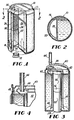
- Fig. 1 is perspective cross-sectional side view of one embodiment of the present invention.
- Fig. 2 is a cross-sectional top view of the self-cooling container of Figure 1.
- Fig. 3 is a perspective cross-sectional side view of another embodiment of the present invention.
- Fig. 4 is an enlarged partial cross-sectional side view of the self-cooling container of Figure 3.
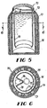
- Fig. 5 is a perspective cross-sectional side view of another embodiment of this invention.
- Fig. 6 is a top view of the separator in the self-cooling container of Figure 5.
- Fig. 7 is perspective cross-sectional side view of yet another embodiment of the present invention.
- Fig. 8 is a cross-sectional top view of the self-cooling container in Figure 7.
- Fig. 9 is a perspective cross-sectional side view of yet another embodiment of the present invention.
- With reference to the drawings, Figures 1 and 2 show a self-cooling container 10 particularly suited for the storage of carbonated soft drinks, fruit drinks, beer and the like. Preferably, the container 10 is a can and is constructed of conventional materials such as aluminum, steel, plastic or the like. The container 10 has a
hollow body 12, an opening means 14, optional insulation means 16, an openable closure means 18, a directing means 28 and acooling chamber 20. The opening means 14 is typically a pull-tab or pop-top as known in the art. The openable closure means 18 provides a tamper-evident function and means to prevent accidental activation of the cooling mechanism. - The
cooling chamber 20 is positioned to provide a narrow passageway between it and the outer wall ofhollow body 12 and is adjacent to openable closure means 18. Thecooling chamber 20 can contain either a refrigerant gas or, preferably, a chemical capable of reacting upon activation to absorb heat. Refrigerant gases are well known in art and include carbon dioxide, hydrocarbons and the like. If refrigerant gases are employed, means for allowing venting of the gases such as any conventional valve (not shown) will be located through openable closure means 18. The preferred cooling mechanism is a chemical cooling means as shown in Figure 1 and described below. - Accordingly, the
cooling chamber 20 has twocompartments cooling chamber 20 includes aflexible rolling diaphragm 30 in contact with the liquid incompartment 22 which can be exposed by opening openable closure means 18. The openable closure means 18 can be any material which will prevent access to theflexible rolling diaphragm 30 until properly opened or removed. Typically, the openable closure means 18 is an adhesive foil, a plastic cap, or the like which is peeled back, opened or otherwise removed by the consumer. - The
compartment 22 ofcooling chamber 20 contains a suitable liquid which will both react when in contact with the chemical contained incompartment 24 and transmit pressure exerted on flexiblerolling diaphragm 30 to rupturable separator means 26. Typically, the liquid employed will be water although other liquids, either organic or inorganic, can be employed depending on the chemical chosen forcompartment 24. The chemical incompartment 24 is selected so as to react with the liquid incompartment 22 upon contact to thereby absorb heat. This reaction, known as an endothermic reaction, is the cooling mechanism which will cool the beverage inhollow body 12 by heat transfer through the wall ofcooling chamber 20. Thus, thecooling chamber 20 is constructed of any suitable heat transfer material including, but not limited to, steel, aluminum or metal alloys. - Suitable chemicals for use in
compartment 24 can be any material which reacts with the liquid incompartment 22 to absorb heat. Such chemicals are well known in the art. When the liquid is water, typical materials include inorganic salts such as alkali metal halides, perchlorates, ammonium salts or the like. The preferred chemical is ammonium nitrate when the liquid is water. - The directing means 28 extends across the circumference of container 10 from the top of container 10 to a position short of the bottom. The directing means 28 directs the flow of beverage such that the beverage flows below the directing means 28 and up between the side of container 10 and the
cooling chamber 20 prior to being dispensed fromopening means 14. In this manner, the next-to-be-consumed portion of the beverage is quickly and efficiently cooled due to the increased ratio of volume (of beverage) to area (of heat transfer wall). The directing means 28 can be made of any material but is suitably a metal or plastic affixed to the top of container 10. - One advantage of the present embodiment is the ability to manufacture container 10 using conventional manufacturing materials and equipment with minimal adaptation. For example, container 10 can be manufactured with conventional can manufacturing technology by preforming
hollow body 12 withcooling chamber 20, preforming the top of container 10 which can have thedirecting means 28 as a integral part thereof or as a separate unit to be placed thereon, inserting intocooling chamber 20 the cooling means which can be either separately manufactured as a preformed unit or assembled withincooling chamber 20, and then inserting the top and separator means 26 into the hollow body. After sealing container 10 with conventional techniques, the openable closure means 18 can be placed on the container using conventional technology. - The operation of the present self-cooling container 10 is particularly simple lending it to quick consumer acceptance. As desired, the consumer lifts or removes the openable closure means 18, applies pressure to the
flexible rolling diaphragm 30 with their finger thereby causing a pressure to be exerted upon and rupturing the rupturable separator means 26. Once the rupturable separator means 26 is ruptured, the chemical fromcompartment 24 enterscompartment 22 and reacts with the liquid incompartment 22. The resulting endothermic reaction cools the beverage. The beverage is consumed through opening means 14 after opening. - It is important to note that rupturable separator means 26 has sufficient durability to keep the contents of
compartment 22 andcompartment 24 from coming into contact during normal handling. On the other hand, rupturable separator means 26 must be capable of rupturing upon the exertion of pressure. Typically, the rupturable separator means can be any thin material or membrane such as rubbers, elastomers, films, resins, plastics or the like. Preferably the material is an elastomer which is stretched or drawn so as to have limited flexibility yet not rupture during normal handling. Optionally, mechanical mixing means for increasing the mixing of the chemical and the liquid can be employed incompartment 24. - Figures 3 and 4 show another embodiment of the present invention which utilizes a directed flow to cool the next-to-be-consumed portion of the beverage. Accordingly,
container 40 hashollow body 42, cooling chamber 44, opening means 46 and directing means 48. The cooling chamber 44 hascompartments Compartment 50 containing the liquid is in contact with a flexible rolling diaphragm (not shown).Compartment 52 contains a chemical. The cooling chamber 44 is similar to that shown in Figures 1 and 2 (20). - Circling cooling chamber 44 is directing
means 48 which forms a "skirt" or a "cup" around the cooling chamber 44. The directing means 48 is affixed tocontainer 40 by any suitable means as known to those skilled in the art. The top of directing means 48 has a projecting lip and ahole 62 for the insertion of adrinking tube 64, suitably a metal or plastic straw. Thedrinking tube 64 hasstopper 66 extending horizontally outward to stop the insertion ofdrinking tube 64 so as not to prohibit the flow of beverage if inserted against separator means 48. The directing means 48, made from a suitable material such as metal or plastic, directs the flow of beverage between the directing means 48 and the cooling chamber 44 prior to exiting through thedrinking tube 64. - Figure 4 shows a sectional enlargement of the top half of
container 40. Thedrinking tube 64 is shown inserted into opening means 46 and thehole 62 of directing means 48. - The operation of
container 40 is generally similar to that of container 10 of Figure 1. The consumer opens or removes openable closure means 58, applies pressure to the flexible rolling diaphragm which ruptures the rupturable separator means 54 and allows the liquid and chemical fromcompartments drinking tube 64 is attached tocontainer 40 in a sanitary plastic wrapper or the like. The consumer opens opening means 46, detaches thedrinking tube 64, opens the wrapper, andinserts drinking tube 64 intohole 62. Thedrinking tube 64 draws the beverage from between directing means 48 and cooling chamber 44 which is cooled as it passes upward. Preferably, there are attachment means (not shown) which keep thedrinking tube 64 in contact with thecontainer 40 resulting in the separator means acting like a giant straw. - Figure 5 and 6 show another embodiment of the present invention.
Container 70 hashollow body 72, coolingchamber 74, opening means 76 and directing means 78. The coolingchamber 74 is a continuous member circling the external wall of thehollow body 72 enclosed by an optional insulatingmeans 73. Typically, the coolingchamber 74 will have at least twoseparate compartments 75 and 77 and a rupturable separator means 79 made from a pliable material. The cooling means is typically two chemicals or a chemical and a liquid as employed in the cooling chambers herein. Such cooling chambers are known in the art and are employed at remote locations to provide cold or heat treatments. Typical applications for such cooling chambers include injury treatment at sporting events. - The directing means 78 has a cup-like shape and extends from the top of
container 70, and stops short of the bottom ofcontainer 70. Figure 6 shows the configuration of the directing means 78 and the relationship of opening means 76 from a top view. The directing means 78 is positioned so as to provide a narrow annular space between it and the external wall ofhollow body 72. - The operation of this embodiment is extremely simple. The consumer will squeeze cooling
chamber 74 to rupture the rupturable separator means 79 therein, thereby allowing the cooling means to be actuated. Thecontainer 70 is opened through opening means 76 where the beverage is dispensed. The beverage flows along the annular space between the directing means 78 and the outside wall ofhollow body 72 and is cooled prior to exiting opening means 76. - Figure 7 and 8 show a self-cooling container which is specifically adapted to activate the cooling mechanism upon opening the container. Accordingly,
container 80 has ahollow body 82, a coolingchamber 84, a opening means 86 and a directing means 88. The coolingchamber 84 is preferably a metal tube, such as a toothpaste tube, which is affixed to the top ofcontainer 80 by any suitable means. The coolingchamber 84 contains a chemical and anelastomer 94 filled with a liquid. Typically, theelastomer 94 is a balloon or other puncturable material which can be filled with a liquid and then placed into the coolingchamber 84 prior to being inserted inhollow body 82. The top of coolingchamber 84 has aplug 90 which forms a seal between the coolingchamber 84 and thehollow body 82. Withinplug 90 is anactuation pin 92 wherein the cutting end is positioned in close proximity toelastomer 94. The directing means 88 extends across the circumference ofhollow body 82 from the top ofhollow body 82 to a position short of the bottom ofhollow body 82. - Again, the operation of
container 80 is very simple. The consumer simply opens the opening means 86 which exerts a force uponactuation pin 92 which inturn punctures elastomer 94. The liquid inelastomer 94 mixes with the chemical in coolingchamber 84 to cause the endothermic reaction. The beverage flows up between the coolingchamber 84 and both the outside wall ofhollow body 82 and the directing means 88 prior to existing opening means 86. - Figure 9 is another embodiment of the present invention which utilizes a chemical mixing means to increase the rate of mixing of the chemical and the liquid in the cooling chamber. The
container 100 hashollow body 102, opening means 114, coolingchamber 120, openable closure means 118, directing means 132, and adrinking tube 134. Thedrinking tube 134, made from any flexible material, is accessible through opening means 114 and attached to directing means 132. The directing means 132 forms a "skirt" or "cup" around thecooling chamber 120, is attached to the top thereof and comes to a position short of the bottom ofcontainer 100. - The cooling
chamber 120 hascompartments compartments chamber 120 has a gaspermeable membrane 128 and anactuation pin 130 which passes through gaspermeable membrane 128, through the liquid incompartment 124 and rests with the cutting end in close proximity to rupturable separator means 126.Activation pin 130 is accessible through openable closure means 118. - The
compartment 122 has a chemical for reacting with the liquid incompartment 124 and also contains a suitable chemical mixing means 136 which, when in contact with the liquid, will react to evolve gas. The gas so evolved will bubble up through the mixture and expedite the mixing of the chemical and the liquid. The evolved gas is then vented through gaspermeable membrane 128 and openable closure means 118. - The chemical mixing means 136 can include any chemical which, when in contact with a suitable liquid such as water, will evolve a non-toxic gas. Preferred chemical mixing means 136 include non-toxic salts, such as alkali metal carbonates, and organic acids with baking soda (sodium bicarbonate) and citric acid being especially preferred when the liquid is water.
- The
actuation pin 130 preferably has a vertically extendingcap 130A which keeps theactuation pin 130 from being pushed through the gaspermeable membrane 126.Collapsible prongs 130B are preferably provided which collapse during insertion and serve to retain theactuation pin 130 from being removed. - The gas
permeable membrane 128 can be any porous material which will form a seal with theactuation pin 130, allow the penetration of gas and retain the liquid incompartment 124. Examples of such materials include gas permeable resins, films, elastomers and polymers. Such materials are known in the art. - The operation of self-cooling
container 100 is as follows. The consumer opens or removes the openable closure means 118, applies pressure toactuation pin 130 which punctures rupturable separator means 126 allowing the liquid, chemical, and chemical mixing means 136 to mix. The gas evolved from the chemical mixing means 136 is vented to atmosphere through gaspermeable membrane 128. The consumer then opens opening means 114 and pulls outdrinking tube 134. The beverage is drawn up from the bottom of thecontainer 100, in between the directing means 132 and thecooling chamber 120 and out throughdrinking tube 134. - A major advantage of all of the embodiments of the present invention is the directed cooling of a predetermined portion of the beverage by employing means for directing the beverage flow. The present embodiments reduce the volume to surface area ratio of the predetermined amount of beverage being cooled by controlling or directing the flow of beverage past the cooling chamber prior to exiting the container. In this manner, the cooling is directed to the next-to-be-consumed portion of the beverage reducing the waiting time required for the consumer to drink cold beverage.
- Thus the present invention, at least in its preferred forms, mitigates the problems associated with the prior techniques by providing a self-cooling container capable of (i) being adapted into current container manufacturing techniques (ii) utilizing a simple and safe cooling mechanism, and (iii) reducing the time required to consume cool beverage; and furthermore provides a self-cooling container which is safe, convenient to use and economical to manufacture; and furthermore provides a self-cooling container which cools predominantly the next-to-be-consumed portion of the beverage; and furthermore provides a self-cooling container which can be introduced into the container manufacturing industries without major alterations in manufacturing machinery or equipment; and furthermore employs an endothermic chemical reaction with inexpensive materials as a self-contained cooling mechanism; and furthermore provides a self-cooling container which can be easily and safely actuated to initiate the cooling process.
- It is to be clearly understood that there are no particular features of the foregoing specification, or of any claims appended hereto, which are at present regarded as being essential to the performance of the present invention, and that any one or more of such features or combinations thereof may therefore be included in, added to, omitted from or deleted from any of such claims if and when amended during the prosecution of this application or in the filing or prosecution of any divisional application based thereon. Furthermore the manner in which any of such features of the specification or claims are described or defined may be amended, broadened or otherwise modified in any manner which falls within the knowledge of a person skilled in the relevant art, for example so as to encompass, either implicitly or explicitly, equivalents or generalisations thereof.
Claims (31)
Applications Claiming Priority (2)
| Application Number | Priority Date | Filing Date | Title |
|---|---|---|---|
| US68876 | 1987-07-01 | ||
| US07/068,876 US4802343A (en) | 1987-07-01 | 1987-07-01 | Self-cooling container |
Publications (2)
| Publication Number | Publication Date |
|---|---|
| EP0297724A2 true EP0297724A2 (en) | 1989-01-04 |
| EP0297724A3 EP0297724A3 (en) | 1990-03-21 |
Family
ID=22085278
Family Applications (1)
| Application Number | Title | Priority Date | Filing Date |
|---|---|---|---|
| EP88304968A Withdrawn EP0297724A3 (en) | 1987-07-01 | 1988-06-01 | Self-cooling container |
Country Status (6)
| Country | Link |
|---|---|
| US (1) | US4802343A (en) |
| EP (1) | EP0297724A3 (en) |
| JP (1) | JPH01124575A (en) |
| AU (1) | AU1582388A (en) |
| BR (1) | BR8802507A (en) |
| ZA (1) | ZA883604B (en) |
Cited By (13)
| Publication number | Priority date | Publication date | Assignee | Title |
|---|---|---|---|---|
| WO1996029255A1 (en) * | 1995-03-23 | 1996-09-26 | Matthew John Searle | Beverage container with heating or cooling insert |
| GB2329459A (en) * | 1997-09-20 | 1999-03-24 | Bass Plc | Self cooling beverage containers |
| GB2329461A (en) * | 1997-09-20 | 1999-03-24 | Bass Plc | Self cooling a can or container |
| US6103280A (en) * | 1997-09-20 | 2000-08-15 | Bass Public Limited Company | Self-cooling containers of beverage and foodstuffs |
| WO2000069748A1 (en) * | 1999-05-13 | 2000-11-23 | Thermotic Developments Limited | Self-heating or self-cooling containers |
| WO2002012807A1 (en) * | 2000-08-07 | 2002-02-14 | Leandro Liberati | Instantaneous cooling system for containers of liquid |
| GB2370629A (en) * | 1998-01-24 | 2002-07-03 | Brandbrew Sa | Cooling containers of beverages |
| US6889507B1 (en) | 1999-08-04 | 2005-05-10 | Crown Cork & Seal Technologies Corporation | Self-cooling can |
| WO2008000274A1 (en) * | 2006-06-30 | 2008-01-03 | Carlsberg Breweries A/S | Chemical cooling |
| US8360048B2 (en) | 2009-03-09 | 2013-01-29 | Heat Wave Technologies, Llc | Self-heating systems and methods for rapidly heating a comestible substance |
| US8556108B2 (en) | 2007-09-26 | 2013-10-15 | Heat Wave Technologies, Llc | Self-heating systems and methods for rapidly heating a comestible substance |
| US8578926B2 (en) | 2009-03-09 | 2013-11-12 | Heat Wave Technologies, Llc | Self-heating systems and methods for rapidly heating a comestible substance |
| DE102015102142A1 (en) * | 2015-02-13 | 2016-08-18 | Do-Tech Gmbh | Cooling element for beverage cans, self-cooling beverage can and method |
Families Citing this family (56)
| Publication number | Priority date | Publication date | Assignee | Title |
|---|---|---|---|---|
| US4911740A (en) * | 1988-08-02 | 1990-03-27 | Schieder Hans B | Pressure responsive valve in a temperature changing device |
| WO1990005669A1 (en) * | 1988-11-17 | 1990-05-31 | Coil Matic, Inc. | Methods and articles for collecting a refrigerant vented from a heat exchange system |
| US4922973A (en) * | 1988-11-17 | 1990-05-08 | Coil Matic, Inc. | Collecting vessels for collecting refrigerants from heat exchange systems and methods |
| US5197302A (en) * | 1989-01-05 | 1993-03-30 | International Thermal Packaging, Inc. | Vacuum insulated sorbent-driven refrigeration device |
| US4925470A (en) * | 1989-04-14 | 1990-05-15 | Chou Tien Fa | Bottom ejection type instant cooling easy-opener with amusement effect |
| US4928495A (en) * | 1989-06-22 | 1990-05-29 | Israel Siegel | Self cooling and self heating container |
| US4993237A (en) * | 1989-09-21 | 1991-02-19 | Heritage Ventures U.S., Ltd. | Self-cooling containers |
| US5214933A (en) * | 1992-01-29 | 1993-06-01 | Envirochill International Ltd. | Self-cooling fluid container |
| US5398850A (en) * | 1993-08-06 | 1995-03-21 | River Medical, Inc. | Gas delivery apparatus for infusion |
| US5578005A (en) * | 1993-08-06 | 1996-11-26 | River Medical, Inc. | Apparatus and methods for multiple fluid infusion |
| US5398851A (en) * | 1993-08-06 | 1995-03-21 | River Medical, Inc. | Liquid delivery device |
| US5571261A (en) * | 1993-08-06 | 1996-11-05 | River Medical, Inc | Liquid delivery device |
| US5408845A (en) * | 1993-09-08 | 1995-04-25 | Microchill Int Ltd | Cooling or chilling apparatus |
| EG20382A (en) * | 1993-10-07 | 1999-02-28 | Envirochill Int Ltd | Self cooling fluid container |
| US5700245A (en) * | 1995-07-13 | 1997-12-23 | Winfield Medical | Apparatus for the generation of gas pressure for controlled fluid delivery |
| AU4190796A (en) * | 1995-12-08 | 1997-07-03 | Ho Kyun Kim | Beverage container with an enclosed cooling system |
| US5943875A (en) * | 1997-12-08 | 1999-08-31 | Envirochill International, Ltd. | Self-cooling fluid container with nested refrigerant and fluid chambers |
| US6843071B1 (en) * | 1999-02-26 | 2005-01-18 | Tempra Technology Inc. | Preparation of refrigerant materials |
| US6178753B1 (en) * | 1999-04-19 | 2001-01-30 | Ontro, Inc. | Container with self-heating module having liquid reactant and breakable reactant barrier at distal end of module |
| KR20020037924A (en) * | 2000-11-16 | 2002-05-23 | 권성문 | Self-cooling container |
| US6962149B2 (en) * | 2001-05-02 | 2005-11-08 | Expressasia.Com Snd. Bhd. | Insertable thermotic module for self-heating can |
| US7004161B2 (en) | 2001-05-02 | 2006-02-28 | Expressasia Berhad | Insertable thermotic module for self-heating cans |
| KR100418906B1 (en) * | 2001-11-21 | 2004-02-14 | 엘지전자 주식회사 | beverage coolant using hydrogen storage alloy |
| KR20020086333A (en) * | 2002-08-28 | 2002-11-18 | 황익현 | Container having a structure for cooling-function therein |
| US7069739B2 (en) * | 2002-12-18 | 2006-07-04 | Porter Michael A | Device for cooling or heating liquids in a bottle |
| WO2005016784A2 (en) * | 2003-08-15 | 2005-02-24 | Gasm Limited | Thermally insulating containers |
| US7025055B2 (en) * | 2004-03-15 | 2006-04-11 | Ontech Delaware Inc. | Tray for selectably heating or cooling the contents |
| US7117684B2 (en) * | 2004-03-15 | 2006-10-10 | Ontech Delaware Inc. | Container with integral module for heating or cooling the contents |
| US20060162344A1 (en) * | 2004-03-15 | 2006-07-27 | Ontech Delaware Inc. | Container with module for heating or cooling the contents |
| US20080190116A1 (en) * | 2004-11-29 | 2008-08-14 | Flamm Shachar | Fluid Conduit Cooling Apparatus and Method |
| FR2885495B1 (en) * | 2005-05-10 | 2007-08-10 | Oreal | PRODUCT PACKAGING AND DISPENSING ASSEMBLY |
| US7260944B2 (en) * | 2005-08-12 | 2007-08-28 | Anthony Michael M | Cryogenic apparatus for chilling beverages and food products and process of manufacturing the same |
| WO2007059151A2 (en) * | 2005-11-14 | 2007-05-24 | Heat Wave Technologies Llc | Improved self-heating container |
| US20080271476A1 (en) * | 2007-02-09 | 2008-11-06 | Elias Langguth | Endothermic beverage cooler |
| US20100078010A1 (en) * | 2007-05-03 | 2010-04-01 | Kolb Kenneth W | Insertable Thermotic Module for Self-Heating Can |
| US20090078711A1 (en) * | 2007-09-26 | 2009-03-26 | Heat Wave Technologies, Llc | Self-heating apparatuses using solid chemical reactants |
| CA2703038C (en) * | 2007-10-15 | 2012-05-01 | Millercoors, Llc | Inserted thermal barrier liner for containers |
| US8336729B2 (en) * | 2007-10-15 | 2012-12-25 | Millercoors, Llc | Thermal barrier liner for containers |
| US8297072B2 (en) * | 2007-10-16 | 2012-10-30 | Millercoors, Llc | Container incorporating integral cooling element |
| US8448809B2 (en) | 2007-10-15 | 2013-05-28 | Millercoors, Llc | Thermal barrier liner for containers |
| EP2194024A1 (en) * | 2008-12-02 | 2010-06-09 | Koninklijke Philips Electronics N.V. | A domestic beverage dispensing device having cooling means |
| WO2010066772A1 (en) * | 2008-12-09 | 2010-06-17 | Carlsberg Breweries A/S | A system and method for providing a self cooling container |
| EP2196752A1 (en) | 2008-12-09 | 2010-06-16 | Carlsberg Breweries A/S | A self cooling container |
| US8477293B2 (en) * | 2009-02-27 | 2013-07-02 | Gemological Institute Of America (Gia) | Method and apparatus for rapidly cooling a gem, including two stage cooling |
| EP2397796A1 (en) | 2010-06-15 | 2011-12-21 | Carlsberg Breweries A/S | A self cooling container and a cooling device |
| WO2011157735A2 (en) | 2010-06-15 | 2011-12-22 | Carlsberg Breweries A/S | A self cooling container and a cooling device |
| US20120204578A1 (en) * | 2010-12-09 | 2012-08-16 | Leavitt David D | Container Cap Containing Cooling Agent Insert |
| US20130098069A1 (en) * | 2011-10-21 | 2013-04-25 | Patrick Collins | Self-Cooling Beverage Can |
| EP2695560A1 (en) | 2012-08-10 | 2014-02-12 | Carlsberg Breweries A/S | A cooling device including coated reactants |
| CA2882357A1 (en) * | 2012-10-15 | 2014-04-24 | Joseph Company International, Inc. | Heat exchange unit for self-cooling beverage container |
| US20140157795A1 (en) * | 2012-12-06 | 2014-06-12 | Kevin Joseph | Self-Contained Thermal Beverage System |
| WO2014166867A1 (en) | 2013-04-08 | 2014-10-16 | Carlsberg Breweries A/S | A system for externally cooling a beverage holder and a method of externally cooling a beverage holder |
| WO2016002597A1 (en) * | 2014-06-30 | 2016-01-07 | シャープ株式会社 | Cooling member |
| WO2019168492A1 (en) | 2018-03-02 | 2019-09-06 | Anthony Michael Mark | Humidification and dehumidification process and apparatus for chilling beverages and other food products and process of manufacture |
| CN111703706B (en) * | 2020-06-30 | 2022-02-25 | 雄县飞洋塑料包装有限公司 | Self-cooled product packaging box |
| CN111703707B (en) * | 2020-06-30 | 2022-02-25 | 雄县飞洋塑料包装有限公司 | Quick refrigerated self-cooling type product packaging box |
Citations (11)
| Publication number | Priority date | Publication date | Assignee | Title |
|---|---|---|---|---|
| US2968932A (en) * | 1958-07-31 | 1961-01-24 | John R Vance | Cooling device |
| US3003324A (en) * | 1959-07-07 | 1961-10-10 | John R Vance | Container for beverages or the like |
| US3213932A (en) * | 1961-09-14 | 1965-10-26 | Gottfurcht Bernard | Varied temperature container |
| FR2136962A1 (en) * | 1971-05-10 | 1972-12-29 | Viguier Rene | |
| DE2150305A1 (en) * | 1971-10-08 | 1973-04-12 | Hoehne Reinhard F Dr | COOLING OF BEVERAGES |
| US3874557A (en) * | 1974-02-07 | 1975-04-01 | Harold E Porter | Self-cooling or self-heating beverage container or the like |
| US3970068A (en) * | 1973-05-29 | 1976-07-20 | Shotaro Sato | Heat exchange package for food |
| US4091632A (en) * | 1976-01-27 | 1978-05-30 | Marchewka Richard B | Beverage cooling device having consumable foodstuff therein |
| US4478346A (en) * | 1982-04-19 | 1984-10-23 | Antonio Valentino Pannutti | Ice-holding and game-adaptable insert cup for drinking container |
| US4640264A (en) * | 1983-10-20 | 1987-02-03 | Tosinobu Yamaguchi | Food and drink warming container |
| FR2587608A1 (en) * | 1985-09-25 | 1987-03-27 | Ukon Murajiroh | CONTAINER FOR AUTOMATIC REFUELING OR COOLING OF BEVERAGES OR FOODS BY EXOTHERMIC OR ENDOTHERMIC REACTION |
Family Cites Families (33)
| Publication number | Priority date | Publication date | Assignee | Title |
|---|---|---|---|---|
| US1897723A (en) * | 1927-04-29 | 1933-02-14 | Walter H Free | Refrigerating device |
| US2460765A (en) * | 1945-10-29 | 1949-02-01 | Herbert E Palaith | Refrigerating means for containers |
| US2556893A (en) * | 1947-10-09 | 1951-06-12 | Zwiebach Leo | Self-cooling container |
| US2757517A (en) * | 1954-09-03 | 1956-08-07 | Jerald F Goldberg | Self-refrigerating container |
| US2746265A (en) * | 1955-01-07 | 1956-05-22 | Evan D Mills | Container cooling device |
| US2805556A (en) * | 1955-11-22 | 1957-09-10 | Wang Wensan | Pocket liquid cooling device |
| US2900808A (en) * | 1955-11-22 | 1959-08-25 | Wang Wensan | Pocket liquid cooling device |
| US2882691A (en) * | 1956-06-15 | 1959-04-21 | Kwik Kold Of America Inc | Beverage cooling means |
| US3229478A (en) * | 1964-12-02 | 1966-01-18 | Alonso Jose | Self-cooled beverage container |
| US3269141A (en) * | 1965-02-26 | 1966-08-30 | Joseph F Weiss | Beverage container |
| US3309890A (en) * | 1965-03-15 | 1967-03-21 | Eugene R Barnett | Refrigerated disposable container |
| US3326013A (en) * | 1966-01-03 | 1967-06-20 | David M Jacobs | Refrigerant-containing food or beverage container |
| US3338067A (en) * | 1966-06-28 | 1967-08-29 | Combined beverage and refrigerant containers | |
| US3373581A (en) * | 1966-08-31 | 1968-03-19 | Wray Jr John Robert | Container arrangement with coolant therein |
| US3494142A (en) * | 1968-04-23 | 1970-02-10 | Wray Jr John Robert | End closure and coolant insert for self-cooling container |
| US3494143A (en) * | 1968-04-26 | 1970-02-10 | Eugene R Barnett | Disposable container |
| US3525236A (en) * | 1968-07-15 | 1970-08-25 | Nariman Solhkhah | Portable self-cooling device |
| US3520148A (en) * | 1968-07-30 | 1970-07-14 | Richard D Fuerle | Self-cooling container |
| AU4281768A (en) * | 1968-08-30 | 1971-02-25 | ROSENFELD and STUART FREDERICK FOX NATHAN | Method of cooling containers |
| US3597937A (en) * | 1969-06-06 | 1971-08-10 | Eugene H Parks | Self-cooling device for beverage container |
| US3620406A (en) * | 1969-12-29 | 1971-11-16 | Raychem Corp | Pull tab and pressure relief valve |
| US3726106A (en) * | 1970-01-07 | 1973-04-10 | W Jaeger | Self-refrigerating and heating food containers and method for same |
| US3881321A (en) * | 1970-02-24 | 1975-05-06 | Drackett Co | Self-cooling disposable liquid container |
| US3759060A (en) * | 1972-06-28 | 1973-09-18 | Marian Cax | Disposable refrigerated container that can be refilled, reused or recycled |
| US3803867A (en) * | 1972-08-31 | 1974-04-16 | S Willis | Thermodynamic beverage cooling unit |
| US3919856A (en) * | 1973-04-06 | 1975-11-18 | William D Beck | Self-chilling container with safety device and method of making same |
| US3852975A (en) * | 1973-04-06 | 1974-12-10 | W Beck | Self-chilling container with safety device and method of making same |
| US3889483A (en) * | 1973-04-30 | 1975-06-17 | Readi Temp | Heat transfer package with shaped frangible ampule |
| US3987643A (en) * | 1974-01-21 | 1976-10-26 | Willis Samuel C | Thermodynamic beverage cooling unit |
| US3842617A (en) * | 1974-01-28 | 1974-10-22 | H Chase | Disposable refrigerated container and refillable refrigerant supply vessel |
| US4204613A (en) * | 1978-03-13 | 1980-05-27 | Marvin Glass & Associates | Liquid cooling and dispensing device |
| US4407356A (en) * | 1981-03-09 | 1983-10-04 | Delau Bruce E | Portable quick chilling and heating appliance |
| US4599872A (en) * | 1984-12-07 | 1986-07-15 | Rist Wesley G | Pour through beverage chiller |
-
1987
- 1987-07-01 US US07/068,876 patent/US4802343A/en not_active Expired - Fee Related
-
1988
- 1988-05-09 AU AU15823/88A patent/AU1582388A/en not_active Abandoned
- 1988-05-20 ZA ZA883604A patent/ZA883604B/en unknown
- 1988-05-23 BR BR8802507A patent/BR8802507A/en unknown
- 1988-05-31 JP JP63134292A patent/JPH01124575A/en active Pending
- 1988-06-01 EP EP88304968A patent/EP0297724A3/en not_active Withdrawn
Patent Citations (11)
| Publication number | Priority date | Publication date | Assignee | Title |
|---|---|---|---|---|
| US2968932A (en) * | 1958-07-31 | 1961-01-24 | John R Vance | Cooling device |
| US3003324A (en) * | 1959-07-07 | 1961-10-10 | John R Vance | Container for beverages or the like |
| US3213932A (en) * | 1961-09-14 | 1965-10-26 | Gottfurcht Bernard | Varied temperature container |
| FR2136962A1 (en) * | 1971-05-10 | 1972-12-29 | Viguier Rene | |
| DE2150305A1 (en) * | 1971-10-08 | 1973-04-12 | Hoehne Reinhard F Dr | COOLING OF BEVERAGES |
| US3970068A (en) * | 1973-05-29 | 1976-07-20 | Shotaro Sato | Heat exchange package for food |
| US3874557A (en) * | 1974-02-07 | 1975-04-01 | Harold E Porter | Self-cooling or self-heating beverage container or the like |
| US4091632A (en) * | 1976-01-27 | 1978-05-30 | Marchewka Richard B | Beverage cooling device having consumable foodstuff therein |
| US4478346A (en) * | 1982-04-19 | 1984-10-23 | Antonio Valentino Pannutti | Ice-holding and game-adaptable insert cup for drinking container |
| US4640264A (en) * | 1983-10-20 | 1987-02-03 | Tosinobu Yamaguchi | Food and drink warming container |
| FR2587608A1 (en) * | 1985-09-25 | 1987-03-27 | Ukon Murajiroh | CONTAINER FOR AUTOMATIC REFUELING OR COOLING OF BEVERAGES OR FOODS BY EXOTHERMIC OR ENDOTHERMIC REACTION |
Cited By (22)
| Publication number | Priority date | Publication date | Assignee | Title |
|---|---|---|---|---|
| US6134894A (en) * | 1995-03-23 | 2000-10-24 | Searle; Matthew J. | Method of making beverage container with heating or cooling insert |
| WO1996029255A1 (en) * | 1995-03-23 | 1996-09-26 | Matthew John Searle | Beverage container with heating or cooling insert |
| US6305175B1 (en) | 1995-03-23 | 2001-10-23 | Matthew J. Searle | Beverage container with heating or cooling material |
| GB2329461B (en) * | 1997-09-20 | 2002-05-29 | Bass Plc | Improvements relating to containers |
| GB2329459A (en) * | 1997-09-20 | 1999-03-24 | Bass Plc | Self cooling beverage containers |
| GB2329461A (en) * | 1997-09-20 | 1999-03-24 | Bass Plc | Self cooling a can or container |
| US6103280A (en) * | 1997-09-20 | 2000-08-15 | Bass Public Limited Company | Self-cooling containers of beverage and foodstuffs |
| GB2363451A (en) * | 1997-09-20 | 2001-12-19 | Bass Plc | Self cooling beverage containers |
| GB2329459B (en) * | 1997-09-20 | 2002-05-08 | Bass Plc | Improvements relating to containers |
| GB2370629A (en) * | 1998-01-24 | 2002-07-03 | Brandbrew Sa | Cooling containers of beverages |
| WO2000069748A1 (en) * | 1999-05-13 | 2000-11-23 | Thermotic Developments Limited | Self-heating or self-cooling containers |
| US6502407B1 (en) | 1999-05-13 | 2003-01-07 | Thermotic Developments Limited | Self-heating or self-cooling containers |
| US6889507B1 (en) | 1999-08-04 | 2005-05-10 | Crown Cork & Seal Technologies Corporation | Self-cooling can |
| WO2002012807A1 (en) * | 2000-08-07 | 2002-02-14 | Leandro Liberati | Instantaneous cooling system for containers of liquid |
| WO2008000274A1 (en) * | 2006-06-30 | 2008-01-03 | Carlsberg Breweries A/S | Chemical cooling |
| US8556108B2 (en) | 2007-09-26 | 2013-10-15 | Heat Wave Technologies, Llc | Self-heating systems and methods for rapidly heating a comestible substance |
| US9603483B2 (en) | 2007-09-26 | 2017-03-28 | Heat Wave Technologies, Llc | Self-heating systems and methods for rapidly heating a comestible substance |
| US8360048B2 (en) | 2009-03-09 | 2013-01-29 | Heat Wave Technologies, Llc | Self-heating systems and methods for rapidly heating a comestible substance |
| US8578926B2 (en) | 2009-03-09 | 2013-11-12 | Heat Wave Technologies, Llc | Self-heating systems and methods for rapidly heating a comestible substance |
| US9175876B2 (en) | 2009-03-09 | 2015-11-03 | Heat Wave Technologies, Llc | Self-heating systems and methods for rapidly heating a comestible substance |
| US9598186B2 (en) | 2009-03-09 | 2017-03-21 | Heat Wave Technologies, Llc | Self-heating systems and methods for rapidly heating a comestible substance |
| DE102015102142A1 (en) * | 2015-02-13 | 2016-08-18 | Do-Tech Gmbh | Cooling element for beverage cans, self-cooling beverage can and method |
Also Published As
| Publication number | Publication date |
|---|---|
| JPH01124575A (en) | 1989-05-17 |
| US4802343A (en) | 1989-02-07 |
| BR8802507A (en) | 1989-01-10 |
| ZA883604B (en) | 1988-11-28 |
| AU1582388A (en) | 1989-01-05 |
| EP0297724A3 (en) | 1990-03-21 |
Similar Documents
| Publication | Publication Date | Title |
|---|---|---|
| US4802343A (en) | Self-cooling container | |
| US4784678A (en) | Self-cooling container | |
| US5626022A (en) | Container with integral module for heating or cooling the contents | |
| US6962149B2 (en) | Insertable thermotic module for self-heating can | |
| US5799775A (en) | Apparatus for dispensing a substance in a liquid beverage | |
| AU582527B2 (en) | Self-contained cooling device for food containers | |
| US5943875A (en) | Self-cooling fluid container with nested refrigerant and fluid chambers | |
| US20100251731A1 (en) | Self-Chilling Beverage Can | |
| US4615463A (en) | Insulated container for a fluid receptacle | |
| US4319464A (en) | Refrigerated container | |
| US20120204578A1 (en) | Container Cap Containing Cooling Agent Insert | |
| US4656838A (en) | Cooling device for a can containing a beverage | |
| US20130025296A1 (en) | Container Cap With Enhanced Shelf-Life Heating Or Cooling Agent Insert | |
| US20140157795A1 (en) | Self-Contained Thermal Beverage System | |
| US3512516A (en) | Combined food packaging and food cooking device | |
| GB2384846A (en) | A device for cooling pressurised beverages | |
| US6173579B1 (en) | Sealed liquid container | |
| WO2001010729A9 (en) | Multi-cell container | |
| EP0892905A1 (en) | Combined valve cup and bottom assembly for self-cooling container | |
| US20230039707A1 (en) | Self-heating or self-cooling system and method | |
| GB2208537A (en) | A device for cooling drink | |
| KR200226868Y1 (en) | Self-cooling container | |
| RU44479U1 (en) | DEVICE FOR CHANGING THE TEMPERATURE OF PREFERRED DRINKS | |
| CA2506726A1 (en) | Self-cooling liquid container | |
| JPH0769103B2 (en) | Freezing |
Legal Events
| Date | Code | Title | Description |
|---|---|---|---|
| PUAI | Public reference made under article 153(3) epc to a published international application that has entered the european phase |
Free format text: ORIGINAL CODE: 0009012 |
|
| AK | Designated contracting states |
Kind code of ref document: A2 Designated state(s): AT BE CH DE ES FR GB GR IT LI LU NL SE |
|
| PUAL | Search report despatched |
Free format text: ORIGINAL CODE: 0009013 |
|
| AK | Designated contracting states |
Kind code of ref document: A3 Designated state(s): AT BE CH DE ES FR GB GR IT LI LU NL SE |
|
| 17P | Request for examination filed |
Effective date: 19900824 |
|
| 17Q | First examination report despatched |
Effective date: 19910424 |
|
| STAA | Information on the status of an ep patent application or granted ep patent |
Free format text: STATUS: THE APPLICATION IS DEEMED TO BE WITHDRAWN |
|
| 18D | Application deemed to be withdrawn |
Effective date: 19910905 |