EP0291144B1 - Burn-in board loader and unloader - Google Patents
Burn-in board loader and unloader Download PDFInfo
- Publication number
- EP0291144B1 EP0291144B1 EP88300559A EP88300559A EP0291144B1 EP 0291144 B1 EP0291144 B1 EP 0291144B1 EP 88300559 A EP88300559 A EP 88300559A EP 88300559 A EP88300559 A EP 88300559A EP 0291144 B1 EP0291144 B1 EP 0291144B1
- Authority
- EP
- European Patent Office
- Prior art keywords
- packages
- burn
- package
- pick
- head
- Prior art date
- Legal status (The legal status is an assumption and is not a legal conclusion. Google has not performed a legal analysis and makes no representation as to the accuracy of the status listed.)
- Expired - Lifetime
Links
Images


Classifications
-
- G—PHYSICS
- G01—MEASURING; TESTING
- G01R—MEASURING ELECTRIC VARIABLES; MEASURING MAGNETIC VARIABLES
- G01R31/00—Arrangements for testing electric properties; Arrangements for locating electric faults; Arrangements for electrical testing characterised by what is being tested not provided for elsewhere
- G01R31/28—Testing of electronic circuits, e.g. by signal tracer
- G01R31/2851—Testing of integrated circuits [IC]
- G01R31/2893—Handling, conveying or loading, e.g. belts, boats, vacuum fingers
-
- G—PHYSICS
- G01—MEASURING; TESTING
- G01R—MEASURING ELECTRIC VARIABLES; MEASURING MAGNETIC VARIABLES
- G01R31/00—Arrangements for testing electric properties; Arrangements for locating electric faults; Arrangements for electrical testing characterised by what is being tested not provided for elsewhere
- G01R31/28—Testing of electronic circuits, e.g. by signal tracer
- G01R31/2851—Testing of integrated circuits [IC]
- G01R31/2855—Environmental, reliability or burn-in testing
- G01R31/286—External aspects, e.g. related to chambers, contacting devices or handlers
- G01R31/2865—Holding devices, e.g. chucks; Handlers or transport devices
- G01R31/2867—Handlers or transport devices, e.g. loaders, carriers, trays
-
- Y—GENERAL TAGGING OF NEW TECHNOLOGICAL DEVELOPMENTS; GENERAL TAGGING OF CROSS-SECTIONAL TECHNOLOGIES SPANNING OVER SEVERAL SECTIONS OF THE IPC; TECHNICAL SUBJECTS COVERED BY FORMER USPC CROSS-REFERENCE ART COLLECTIONS [XRACs] AND DIGESTS
- Y10—TECHNICAL SUBJECTS COVERED BY FORMER USPC
- Y10T—TECHNICAL SUBJECTS COVERED BY FORMER US CLASSIFICATION
- Y10T29/00—Metal working
- Y10T29/53—Means to assemble or disassemble
- Y10T29/5313—Means to assemble electrical device
- Y10T29/53174—Means to fasten electrical component to wiring board, base, or substrate
- Y10T29/53183—Multilead component
-
- Y—GENERAL TAGGING OF NEW TECHNOLOGICAL DEVELOPMENTS; GENERAL TAGGING OF CROSS-SECTIONAL TECHNOLOGIES SPANNING OVER SEVERAL SECTIONS OF THE IPC; TECHNICAL SUBJECTS COVERED BY FORMER USPC CROSS-REFERENCE ART COLLECTIONS [XRACs] AND DIGESTS
- Y10—TECHNICAL SUBJECTS COVERED BY FORMER USPC
- Y10T—TECHNICAL SUBJECTS COVERED BY FORMER US CLASSIFICATION
- Y10T29/00—Metal working
- Y10T29/53—Means to assemble or disassemble
- Y10T29/5313—Means to assemble electrical device
- Y10T29/53191—Means to apply vacuum directly to position or hold work part
-
- Y—GENERAL TAGGING OF NEW TECHNOLOGICAL DEVELOPMENTS; GENERAL TAGGING OF CROSS-SECTIONAL TECHNOLOGIES SPANNING OVER SEVERAL SECTIONS OF THE IPC; TECHNICAL SUBJECTS COVERED BY FORMER USPC CROSS-REFERENCE ART COLLECTIONS [XRACs] AND DIGESTS
- Y10—TECHNICAL SUBJECTS COVERED BY FORMER USPC
- Y10T—TECHNICAL SUBJECTS COVERED BY FORMER US CLASSIFICATION
- Y10T29/00—Metal working
- Y10T29/53—Means to assemble or disassemble
- Y10T29/5313—Means to assemble electrical device
- Y10T29/53261—Means to align and advance work part
Definitions
- the present invention relates generally to the field of automated apparatus for handling electronic circuit components and, more particularly, to automated apparatus for use in the art of burning-in circuit components prior to their distribution and use. Still more particularly, the present invention is directed to the art of automated insertion and removal of electronic integrated circuit (IC) packages into and out of sockets on printed circuit (PC) boards, and to the art of testing burn-in boards.
- IC integrated circuit
- IC packages are mass-produced and installed in electronic circuits within highly sophisticated, complex, and costly equipment. As with many mass-produced products, IC packages are prone to failure, in some cases within the first one thousand hours of operation.
- the complexity of equipment within which such packages are installed makes post-installation failures highly undesirable. For example, when equipment reaches the final inspection stage of production, before failures are detected, the high level skills required for inspection and repair add a significant cost to production expenses. Even more significantly, when the product has been installed in the field and a service technician must make warranty repairs, the costs thereby incurred can have a significant effect on profitability. More and more often, however, post-installation failures simply cannot be tolerated because the potentially disastrous consequences. As a result, manufacturers of electronic equipment are demanding ever greater quality and dependability in commercial grade IC packages.
- Burn-in One of the methods for detecting flawed IC packages is referred to generally as "burn-in". According to burn-in techniques, IC packages are stressed within their physical and electrical limits prior to installation, whereby those packages likely to become early failures in completed equipment can be discovered.
- Burn-in involves placing a large number of IC packages on one or more PC boards ("burn-in boards"); placing the burn-in boards with the packages mounted thereon in a chamber whose environment, particularly temperature, is controllable; applying direct current (dc) biases to each package on each board in such a manner as to forward and reverse bias as many of the package's junctions as possible, and/or actively clocking each package to its maximum rated conditions, such application of dc biases, clock signals, and loads being accomplished substantially simultaneously to each package; removing the component boards from the chamber after the IC packages have been subjected to the environmental condition of the chamber and the biases, clock signals, and loads for a designated period of time; and removing the IC packages from the burn-in boards.
- dc direct current
- the IC packages can be electrically tested either within or outside the burn-in chamber, depending on the sophistication of the particular chamber, by applying a room temperature test of critical dc parameters, e.g., input currents and thresholds, output voltages and currents, and, in the case of digital components, by making a functional test to verify truth table performance. In this way, the packages that fail during burn-in are detected and segregated from those that do not fail.
- critical dc parameters e.g., input currents and thresholds, output voltages and currents
- a second method for improving the quality control of IC packages is to verify that the IC packages function properly according to their minimum rated electrical operational specifications. Typically, after or during "burn-in" each IC package is tested across a broad range of parameters and, in some cases, graded as to its performance. Thereafter, the IC packages may be sorted into groups according to the performance grades.
- burn-in and test processes although successful in reducing expenses associated with flawed IC packages, are not themselves without expense. Substantial expenditures are necessary to purchase or to construct burn-in chambers, burn-in boards, and test equipment. Personnel must be employed and trained to operate the equipment and to monitor the time-consuming processes. So substantial are the investments that independent businesses provide burn-in and test services to a variety of manufacturers. Cost effectiveness of the burn-in and test processes is therefore essential.
- German Gebrauchsmuster G 86 26 502.4 also discloses apparatus for testing printed circuit board assemblies and includes a tiltable support for the boards.
- Automated handling enables the use of a computer to track and document the progress of each IC package through the burn-in process.
- automated handling equipment may be used to achieve a higher throughput of IC packages more efficiently than could be achieved otherwise.
- a single automated loader for example, can easily replace eight or more very efficient employees assigned to the tedious task of loading burn-in boards.
- automated handling equipment provides improved reliability and consistency of work product.
- Automated handling equipment is generally very expensive.
- Automated burn-in board loaders, unloaders, and testers because of the distinctly different nature of their operation, generally are sold as independent units, any one of which may costs from 20,000 to 50,000 or more.
- the substantial nature of the capital investment required for purchase of this equipment in spite of the known advantages of its use, represents an impediment to its purchase by even large manufacturers. Accordingly, there exists a need in the art for reasonably priced automated handling equipment.
- One means by which this end may be accomplished is to design an improved apparatus which, in spite of the distinctly different nature of loaders, unloaders, and testers, combines the three functions in a single, efficient machine.
- an apparatus for loading IC packages into and unloading IC packages from sockets mounted on printed circuit boards comprising a support for supporting the printed circuit boards in a horizontal position, a transport device affixed to said support for inserting IC packages into and extracting IC packages from sockets on said printed circuit boards, and a delivery device affixed to said transport device for delivering IC packages to and from said transport device, characterised in that said support is rotatable from the horizontal in a first direction to convey the IC packages by gravity from a storage position to the transport device and rotatable from the horizontal in a second direction opposite the first direction to convey the IC packages by gravity from the transport device to the storage position.
- the loader/unloader apparatus further includes a control system for receiving electrical signals from sensors and delivering electrical signals to apparatus so as to properly position the burn-in boards beneath the transport means and so as to ensure smooth operation of the automated insertion and extraction process.
- the rotatable support means may include a platform which is rotatable about its axis in both the clockwise and counter-clockwise direction.
- a table may be movably affixed to the platform for supporting one or more burn-in boards and for moving the burn-in boards in the forward, rearward, and lateral directions so as to position rows of sockets beneath the transport means.
- the transport means may include a vacuum actuated pick-up head for lifting IC packages and may have air cylinders affixed to produce vertical and horizontal motion of the pick-up head over sockets on the burn-in board and over the delivery means.
- the delivery means includes a track along which the IC packages may slide, either towards the transport means when the platform is in the loading position, or away from the transport means and towards IC package storage tubes when the platform is in the unloading position.
- the delivery means may also include a gate mechanism for delivering the IC packages to and from the transport means one IC package at a time.
- the loader/unloader apparatus may also include a tapered wedge member attached to the delivery channel used to partially unseat DIP@s from their sockets so as to permit removal of the DIP from its socket by the vacuum actuated pick-up head.
- the invention may include socket testing means allowing functional tests to be performed on the sockets so as to ensure their operativeness.
- testing means may include test-heads having a plurality of downwardly extending electrical leads for mating with the IC sockets to be tested, and electrical conductors attached to those leads providing communication means between the test-heads and the control system.
- Burn-in refers generally to the technique whereby integrated circuit (IC) packages are stressed, and sometimes tested, within their physical and electrical limits prior to their sale or distribution so that those packages likely to become early failures in complicated equipment can be discovered, and so that IC packages, in some cases, can be graded and sorted according to performance specifications.
- the burn-in technique generally includes loading the IC packages into sockets on burn-in boards, placing the burn-in boards in a chamber whose environment, particularly temperature, is controllable, applying electrical test signals to the boards while subjecting the IC packages to the maximum temperature reading therefor, removing the burn-in board from the chamber, and unloading the IC packages from the burn-in boards.
- a loader/unloader apparatus 10 for automatically loading IC packages (not shown) into sockets 14 on one or more burn-in boards 16.
- Typical IC packages are dual in-line packages ("DIP's"), which comprise a parallelepiped body portion having from four to sixty-four electrical leads of a generally L-shaped cross-section extending out and down from the opposing sides of the body.
- the sockets 14 mounted on the burn-in boards 16 include socket contacts defining slots for receiving electrical leads on IC packages.
- the IC package may be a surface mounted device ("chip") including small outline integrated circuits (SOIC's), plastic leaded chip carriers (PLCC's), ceramic leaded chip carriers (CLCC's), or leadless chip carriers (LCC's).
- SOIC also comprises a generally parallelepiped body portion having electrical leads extending from opposing sides of the body.
- the electrical leads may have either a J-shaped or an S-shaped ("gull wing") cross-section permitting the lead to lie on the surface of the socket 14 rather than being inserted into slots in the socket.
- the PLCC, CLCC, and LCC have bodies which are of a square or rectangular geometry with a relatively thin cross-section, giving these IC packages an overall wafer-shaped appearance.
- the PLCC and the CLCC have mutliple electrical leads positioned flush with or bent into close proximity with the body of the package, while the LCC has conductive coatings applied at select areas on the major body surfaces.
- the sockets 14 therefore include socket contacts having conductive coatings on the surface of the socket.
- the loader/unloader 10 shown in FIG. 1 may be used to load all types of IC packages on and unload them from burn-in boards. Additionally, the apparatus may be used to selectively unload, and thereby sort, chips after the burn-in process has been completed.
- loader/unloader apparatus 10 is shown in a commercial package and is comprised generally of support structure 20 and rotatable platform 30.
- Support structure 20 includes a base portion 22 for supporting platform 30 and a stanchion portion 24.
- the support structure 20 comprises a frame (not shown) manufactured from structural tubing or other heavy gauge metal which is covered with sheet metal panels, such as panel 28.
- Base portion 22 and stanchion portion 24 also enclose certain drive mechanisms and control apparatus hereafter described in greater detail.
- platform 30 is generally comprised of left and right end panels 32 and 34 respectively, front panel 36, rear panel 38, and bottom panel 40, these panels being bolted, welded or otherwise suitably fastened together at substantially right angles so as to form a box-like structure.
- canopy 42 is rigidly attached to right end panel 34, front panel 36 and rear panel 38 and extends approximately one-third the length of platform 30, thereby extending above a portion of bottom panel 40 and forming a partial enclosure into which burn-in boards 16 may be positioned as described in greater detail below.
- Lateral cross bars 41 span the width of platform 30 and are spaced above burn-in boards 16 where they are rigidly affixed to front and rear panels 36 and 38 so as to provide slidable support for a plurality of loader/unloader mechanism 140, also hereafter described in greater detail.
- platform 30 is rotatable about an axis 44 which extends generally perpendicular to front panel 36 and rear panel 38.
- Platform 30 rotates about axis 44 on front shaft 46 and rear shaft 48.
- Shafts 46 and 48 are coaxially aligned and keyed to support plates 49 which are then bolted to front panel 36 and rear panel 38.
- Front shaft 46 is received through apertures in front panel 36 and in framing member 21 of base 22 and is supported by a flange-type bearing 51 which is bolted to framing member 21.
- Rear shaft 48 is received through bushings 35, positioned in apertures in rear panel 38 and framing member 23 of base 22, and is rigidly attached to drive sprocket 60.
- loader/unloader apparatus 10 is shown in loading position 11, i.e., the position in which loader/unloader mechanism 140 loads IC packages delivered from IC package storage tubes 17 into sockets mounted on burn-in-board 16.
- FIG. 2 also illustrates loader/unloader apparatus 10 in unloading position 13 (dashed line) in which loader/unloader mechanism 140 extracts IC packages from sockets on burn-in board 16 and transports the packages to storage tubes 17.
- FIG. 3 there is shown a partial rear view of the lower portion of stanchion 24 of support structure 20 with a rear panel 28 removed, thereby revealing the drive apparatus used to rotate platform 30.
- drive motor 70 is affixed within stanchion 24 in a vertical orientation.
- Motor shaft 68 is connected through coupling 67 to worm-gear 66 which engages the teeth of drive sprocket 60.
- Drive motor 70 such as Model No. M092 manufactured by the Superior Electric Company is reversible.
- a controller not shown
- drive motor 70 Upon receipt of the appropriate signal from a controller (not shown), such as a microprocessor hereafter described in greater detail, drive motor 70 will turn worm-gear 66 and rotate drive sprocket 60 in a clockwise direction as viewed in FIG.
- a potentiometer 302 mounted on front shaft 46 within support structure 20, shown in FIG. 4, sends a continuous analog voltage signal to the controller, thereby indicating the angular position of platform 30.
- the controller On achieving the desired degree of rotation, which may be, for example, 35 degrees from the horizontal for loading certain sized chips and DIPs, the controller will stop drive motor 70 and halt the rotation of platform 30.
- motor drive 70 and worm gear 66 Upon receipt of another control signal from the controller, such as when loading has been completed, motor drive 70 and worm gear 66 will rotate drive sprocket 60 in the counter-clockwise direction as viewed in FIG. 3, and thereby rotate platform 30 back to the horizontal position shown in FIG. 1 or to the unloading position 13 as depicted in FIG. 2. Potentiometer 302 is again employed to continuously signal the angular position of platform 30.
- burn-in board 16 is mounted on table 106, with portions of each cut-away to depict table carriage 92 and table shuttle 89; table 106, table carriage 92 and table shuttle 89 all cooperatively interact to maneuver burn-in board 16 and sockets 14 beneath the loader/unloader mechanisms 140, depicted in FIG. 1, as hereafter described.
- brackets 80 which rigidly support cross members 82 above bottom panel 40.
- Cylindrical carriage support rods 84 are bolted to cross members 82, thereby forming a track on which table carriage 92, described below, may traverse in either the forward or rearward direction, arrows 108 and 110 depicted in FIG. 4 defining the forward and rearward directions respectively.
- the forward and rearward movement of table carriage 92 is controlled by carriage drive motor 86 which is secured to cross member 82 nearest to right end panel 34.
- the shaft of carriage drive motor 86 is connected to a threaded cylindrical metallic rod or screw 90 which is supported at both ends thereof by screw journal boxes 91, the left most screw journal box 91 being bolted to left cross member 82 and right screw journal box 91 being secured to motor mounting bracket 88, which, in turn, is bolted to right cross member 82.
- Table carriage 92 slidably supported on carriage support rods 84, includes rear runner 94, front runner 96, carriage support housings 97 and shuttle support rods 98.
- Rear runner 94 and front runner 96 are generally L-shaped in cross section and include a vertical portion and a bottom flat portion to which a pair of carriage support housings 97 are attached.
- the carriage support housings 97 are slidably affixed to carriage support rods 84, carriage support rods 84 passing through bushings contained therein, such as Thompson recirculating ball bushings.
- Shuttle support rods 98 extend between, and are rigidly attached to, the vertical portions of runners 94 and 96, thereby forming a track on which table shuttle 89 may traverse laterally in the direction denoted by arrows 111 and 113 in FIG. 4, table shuttle 89 providing support for and being affixed to table 106 by suitable fastening means such as bolts (not shown).
- Shuttle support rods 98 are slidably received through bushings in four shuttle support housings 99 which are fastened to the sides of shuttle 89, such bushings also typically being Thompson recirculating ball bushings. Lateral movement of shuttle 89 and table 106 in directions 111 or 113 is initiated by shuttle drive motor 102 which is secured to front runner 96.
- the shaft of shuttle drive motor 102 is connected to a second threaded cylindrical metallic rod or screw 104 which passes through a threaded coupling 103 attached to underside of table shuttle 89.
- table 106 and burn-in board 16 are advanced in either the forward direction 108 or rearward direction 110 by means of the rotation of screw 90.
- Rotational motion of the screw 90 generated by energizing carriage drive motor 86, is translated to forward and rearward linear motion of table 106 by means of threaded coupling 93 affixed to forward shuttle support rod 98.
- Threads of coupling 93 cooperatively engage the threadlike groves extending continuously about the circumference of screw 90, causing table carriage 92 to advance linearly as screw 90 rotates.
- table 106 and burn-in board 16 are advanced in a lateral direction 111 or 113 by means of the rotation of screw 104.
- Screw 104 passes through threaded coupling 103 which is secured to table shuttle 89.
- Rotational motion of screw 104 generated by energizing shuttle drive motor 102, is translated into linear motion of table 106 by means of threaded coupling 103 whose threads cooperatively engage the groves of screw 104, causing the table 106 to advance laterally in a direction perpendicular to the forward and rearward directions depicted by arrows 108 and 110 respectively.
- Burn-in board 16 is removably affixed in a predetermined position to table 106 by suitable clamping means such as pneumatic actuated clamp 19 shown in FIG. 1.
- IC sockets 14 are arranged on the burn-in board 16 in a substantially close fitting array comprised of rows which are aligned as indicated by the arrow at 112, and in columns which are aligned as indicated by the arrow at 114.
- IC sockets 14 aligned in a row are arranged side by side; IC sockets 14 aligned in a column are arranged end to end.
- the slidable nature of the attachment of the loader/unloader mechanisms 140 onto cross bars 41, shown best in FIG. 1, facilitate adjustment of the lateral position of the loader/unloader mechanisms 140 so as to accommodate a variety of sizes of burn-in boards having differing spacing between columns of sockets.
- loader/unloader apparatus 10 includes a control system, hereinafter described in greater detail, which among other functions serves to direct the proper positioning of table 106 and burn-in board 16 which respect to loader/unloader mechanisms 140 so as to align a column of sockets 14 on burn-in board 16 with each loader/ unloader mechanism 140.
- positioning of table 106 and burn-in board 16 is accomplished by controlling the operation of carriage drive motor 86 and shuttle drive motor 102.
- These motors are precisely controllable stepper motors whose direction of rotation is reversable and whose degree of rotation is accurately controlled according to step pulses generated by the controller.
- These drive motors 86 and 102 may be, for example, model numbers M063 as manufactured by the Superior Electric Company.
- the present invention does not require the use of a series of position sensors. Instead, the controller utilized in loader/unloader apparatus 10 only requires sensors to indicate when table carriage 92 and table shuttle 89 are in their starting or "home" positions. Upon receipt of signals indicating that table carriage 92 and table carriage 89 are in their respective home positions, the controller can drive carriage 92 and shuttle 89 to the proper starting position for loading or unloading IC packages on burn-in board 16, the exact positioning of which will depend upon a variety of factors, such as the number and size of burn-in boards and the size and type of IC packages to be handled.
- support rod 130 is affixed to bottom panel 40 parallel to support rods 84 by bracket 131.
- Affixed to support rod 130 are photoelectric sensors 132 and 133, such as model no. CLI-355, manufactured by the Clairex Electronics Company, each having a channel formed in the upper surface thereof for detecting the presence of downwardly extending indicator 134 which is rigidly attached to rear runner 94 of table carriage 92.
- Indicator 134 and photoelectric sensors 132 and 133 are positioned such that indicator 134 may pass through the channel in their upper surfaces as table carriage 92 moves linearly in forward or rearward direction 108 and 110.
- Photoelectric sensor 132 signals the limit of travel in the rearward direction 110 and signals the home position in the forward and rearward directions for each loading or unloading sequence. While the movement and position of table carriage 92 is precisely controlled through the use of a stepper drive motor as described above, photoelectric sensor 133 serves as a back-up or safety device to limit forward travel of table carriage 92 should a control malfunction occur. Similarly, photoelectric sensor 135, which may also be model no CLI-355, manufactured by the Clairex Electronics Company, is mounted on table shuttle 89 and positioned so as to receive indicator 136 which is attached to and extends from forward runner 96. Photoelectric sensor 135 signals the limit of travel of table shuttle 89 in the lateral direction 113 and signals the home position in the lateral direction for any loading or unloading sequence.
- FIG. 10 shows a block diagram disclosing the basic organization of the control system for the loader/unloader apparatus 10.
- the control system is centered around a microprocessor 300, such as Model No. 2003XC manufactured by Texas Microsystems, Inc.
- the microprocessor 300 is housed in support structure 20.
- the loader/unloader apparatus 10 includes a front control panel 25, shown also in FIG. 1, having a plurality of push buttons arranged thereon for an operator to enter set-up parameters and to command certain operations of the loader/unloader apparatus 10.
- the commands which may be communicated by an operator through control panel 25 to the microprocessor 300 include start, stop, run, and step commands. Certain tests of loader/unloader apparatus 10 may also be initiated from control panel 25.
- Floppy disk drive 27, supported in base structure 22, provides a means through which to input operating instructions and data to microprocessor 300. Input and output messages are communicated to the operator via monitor 26 which is supported by and housed in stanchion 24 as shown in FIG. 1.
- the control system comprises additional input and output subsystems.
- the first additional input subsystem 310 is for communicating the angular position of platform 30 and comprises potentiometer 302, shown in FIG. 4, which continuously transmits an analog voltage signal to microprocessor 300 indicating the angular position of platform 30.
- An output subsystem 318 is provided to start and stop platform drive motor 70 as required for the various IC package loading, unloading, and sorting functions to be performed by loader/unloader apparatus 10.
- Input subsystems 312, 314, and 316 are also provided for receiving signals from photoelectric sensors 132, 133, and 135 respectively, located within platform 30 as shown in FIG. 4. As explained above, photoelectric sensors 132 and 135 define the starting or "home" position of table 106 within platform 30. In response to signals from photoelectric sensors 132 and 135, through output subsystems 320 and 322, microprocessor 300 operates carriage motor 86 and shuttle drive motor 102 to advance table 106 and burn-in board 16 in the forward, rearward, and lateral directions so as to position the proper row and column of sockets beneath the loader/unloader mechanisms 140. Input subsystem 134, including photoelectric sensor 133 is provided to signal microprocessor 300 should the carriage drive control system malfunction, allowing table carriage 92, shown in FIG. 4, to advance too far in the forward direction 108.
- the control system for loader/unloader apparatus 10 also includes a vacuum source subsystem 324 which includes hardware by which microprocessor 300 controls actuation of pick-up heads 210 of loader/unloader mechanisms 140 as hereafter described in greater detail.
- a vacuum subsystem sensor 326 is provided to monitor the vacuum generated and available at the pick-up heads of loader/unloader mechanisms 140 so as to provide an input signal to microprocessor 300 indicating whether a particular loader/unloader mechanism 140 has successfully lifted an IC package by means of the vacuum generated and supplied to that loader/unloader mechanism 140.
- a pneumatic source subsystem 330 which includes hardware by which microprocessor 300 controls actuation of clamp 19 and actuation of air cylinders 214 and 216, a part of the loader/unloader mechanism 140, hereafter described in greater detail.
- the control system finally includes a socket test subsystem 328.
- Socket test subsystem 328 including test-heads 400 hereinafter described in greater detail, is used to transmit test signals to, and record the response from, sockets which are to be loaded with IC packages for burn-in. By testing sockets before loading, defective sockets can be identified and their location recorded by microprocessor 300. During the loading process then, IC packages will not be inserted into the defective sockets.
- Loader/unloader mechanism 140 is employed to load and unload all types of IC packages, namely both chips and DIP's.
- the loading sequence for both types of IC packages is identical although slight modifications to the loader/unloader mechanism 140 are made to accommodate the physical differences between chips and DIP's.
- the loading sequence for IC packages will be described with reference to FIGS. 5A, 5B, 6 and 7 which depict loading of chips.
- the modifications to loader/unloader mechanism 140 required for loading DIP's will be noted.
- the unloading of chips is described with reference to FIGS. 8A and 8B.
- the modifications to loader/ unloader mechanism 140 required to unload DIP's from sockets on a burn-in board are described with reference to FIGS. 9A, 9B and 9C.
- Loader/unloader mechanism 140 generally includes transport device 150, gate mechanism 170, and delivery channel 190. Due to the force of gravity, when platform 30 is in the loading position, delivery channel 190 provides a steady supply of IC packages 12 in serial fashion to the transport device 150 for insertion into sockets 14 on burn-in board 16. Gate mechanism 170 ensures that the IC packages 12 advance to transport device 150 one IC package at a time.
- Delivery device 190 includes track 192, track cover 194 and track base 196.
- track 192 includes a channel 193 in which IC packages 12 may slide.
- the width of channel 193 is dependent upon the width of the IC package then being loaded, the width of channel 193 being only slightly wider than IC package 12, so as to insure the proper orientation and position of the IC package.
- Transport device 150 picks up IC package 12 from delivery track 192 and loads it on burn-in board 16.
- Track 192 is configured differently when loader/unloader mechanism 140 loads DIPs rather than chips on a burn-in board. Instead of having a channel 193 formed therein, track 192 instead is formed with a ridge, generally rectangular in cross section and having a width slightly less than the distance between the rows of leads extending from the DIP, allowing the DIP to straddle and slide upon the ridge.
- Track base 196 is attached to track base 196 by recessed screws 198.
- Track base 196 also includes pins 199 and a captured cap screw 200 for fastening track base 196 to support plate 43, which in turn is clamped to lateral cross bars 41.
- cap screw 200 is the sole means for attaching delivery channel 190 and loader/unloader mechanism 140 to platform 30, loader/unloader mechanisms 140 can be quickly and easily changed when it is desirable to load or unload a different size or type of IC package than those previously handled.
- Track base 196 includes conduits 249 formed therein for connection to pneumatic hoses 250 which control the operation of transport mechanism 150, as explained below.
- Track cover 194 L-shaped in cross section, includes a side plate 195 and top plate 197 and is attached to track 192 by screws through side plate 195. Top plate 197 retains IC packages 12 in position in track 192 as the packages are fed toward gate mechanism 170 by the force of gravity.
- gate mechanism 170 is attached to top plate 197 of track cover 194.
- Gate mechanism 170 includes enclosure 172, gate rod 184, left and right gate pins 180 and 182 respectively, bushing blocks 174 and support blocks 183.
- enclosure 172 is generally box-like in configuration and is fastened to track cover 194 through bushing blocks 174 by spring loaded fasteners 176.
- Bushing blocks 174 are secured to enclosure 172 by flush mounted fasteners (not shown).
- the male portion of spring loaded fasteners 176 are recessed within top plate 197 of track cover 194 so as not to impede the flow of IC packages 12 along track 192.
- Gate rod 184 passes through enclosure 172 and is slidably received within coaxially aligned apertures in bushing blocks 174 allowing reciprocal motion of gate rod 184 therethrough.
- Left and right gate pins 180 and 182 are retained in position within enclosure 172 by support blocks 183 which are secured to enclosure 172 by flush mounted screws on other suitable fasteners (not shown), the gate pins 180 and 182 being separated by a distance greater than the length of the IC package being handled, that distance typically approximating one and one-half times the length of the IC package.
- Gate pins 180 and 182 are interally threaded and fitted with a short length of rubber tubing 181 which is retained within the threaded portion of gate pins 180 and 182 through compression fit.
- An indentation 186 is formed on gate rod 184 so that as rod 184 reciprocates within enclosure 172, indentation 186 moves between positions above left gate pin 180 and above right gate pin 182. As indentation 186 moves above either gate pin 180 or 182, spring 185 forces the respective gate pin upward where it is captured by indentation 186. As gate rod 184 reciprocates further and indentation 186 moves correspondingly, indentation 186 cams the captured gate pin 180 or 182 downwardly such that the end of the tubing 181 protrudes through holes or slots formed in top plate 197 of track cover 194.
- tubing 181 of one or both of gate pins 180 and 182 will extend through top plate 197 of track cover of 194 at all times.
- the length of gate pins 180 and 182 and of tubing 181 are of such dimensions so as to ensure that tubing 181 will impede the flow of IC packages along delivery channel 190 when gate pins 180 and 182 are not captured by indentation 186 of gate rod 184.
- a reference to gate pins 180 and 182 shall refer to the entire gate pin assembly comprising both the screw portion and the length of tubing, it being understood that only tubing 181 actually extends into delivery channel 190.
- transport device 150 includes a vacuum actuated pickup head 210, slide block 212, vertical air cylinder 214, horizontal air cylinder 216, adjustable stops 218, front and rear face plates 224 and 226 respectively, and end plate 228 (front face plate shown in FIGS. 1 and 2).
- Front and rear face plates 224 and 226 are attached to delivery channel 190 by flush mounted bolts 205.
- Front and rear face plates 224 and 226 are also fastened to end plate 228 and spacer block 229 by suitable flush mounted fasteners (not shown).
- One end of horizontal cylinder 216 threadedly engages spacer block 229.
- Piston rod 221 extending from horizontal cylinder 216 is slidably received through an aperture formed in spacer block 229 and threadedly engages slide block 212.
- Slide block 212 is disposed between front plate 224 and rear plate 226.
- Guide pins 230 extend from slide block 212 at substantially right angles to the parallel planes formed by front face plate 224 and rear face plate 226, guide pins 230 being received within slots 227 formed in face plates 224 and 226, thereby supporting slide block 212 as piston rod 221 reciprocates within horizontal cylinder 216.
- Vertical cylinder 214 is threadedly engaged to the top of slide block 212.
- Piston rod 220 extending from vertical cylinder 214 is slidably received through an aperture formed in slide block 212 and threadedly engages vacuum actuated pick-up head 210.
- Pick-up head 210 a metalic block, includes an internal conduit (not shown) one end of which terminates at the lower surface 211 of pick-up head 210, surface 211 forming the surface against which IC packages are secured during transport by a vacuum source which is connected to the other end of the internal conduit by a vacuum line or hose (not shown).
- the vacuum line passes through opening 234 formed in rear plat 226, opening 234 permitting the horizontal and vertical movement the vacuum line as piston rods 220 and 221 reciprocate so as to position pick-up head 210.
- horizontal cylinder 216 includes piston rod 222 extending from the rearward end of cylinder 216, piston rod 222 threadedly engaging one end of connection bar 204.
- connection bar 204 is slotted so as to receive gate rod 184 and permit reciprocation therethrough.
- connection bar 204 slides along gate rod 184 unimpeded until engaging collars 202 or 203 which are fastened to gate rod 184 by set screws or other suitable means (not shown).
- gate rod 184 actuates gate mechanism 170 as hereinafter explained in more detail.
- an operator Before initiating the loading sequence of loader/unloader 10, an operator inserts the open end of an IC package storage tube 17 to each delivery channel 190 by clamping device 191 as depicted in FIG. 1.
- the operator additionally places a burn-in board 16 to table 106.
- the operator then depresses the "run" pushbutton on console 25 which first actuates pneumatic clamp 19, securing the burn-in board to table 106, and next rotates platform 30 into the loading position 11 as depicted in FIG. 2, with platform 30 sloping from right to left at an incline, for example, of approximately 35 degrees.
- the loading angle may be lesser or greater than 35 degrees.
- the angle of incline must be steep enough to ensure the packages will properly feed through delivery channel 190, but not be so steep that the packages could be damaged as they slide from storage tubes 17 until the frontmost IC package 50 comes to rest within gate mechanism 170 as depicted in FIG. 5A.
- FIG. 5A as platform 30 rotates from a substantially horizontal position shown in FIG. 1, to the loading position 11 as shown in FIG. 2, the IC packages 12 maintained in the storage tubes 17 slide into track 192 of delivery channel 190 due entirely to the force of gravity.
- Vertical cylinder 214 is initially positioned as shown in FIG. 5A with piston rod 220 completely retracted such that pick-up head 210 is in its uppermost position. Because of the interconnection between vertical piston 214, slide block 212, and piston rod 221, with vertical cylinder 214 in its initial position, piston rod 222 of horizontal cylinder 216 is fully extended, which when achieving that position caused connection bar 204 to contact and push against collar 203, thereby positioning indentation 186 of gate rod 184 above right gate pin 182.
- right gate pin 182 is captured by the indentation 186 of gate rod 184 so as not to extend into delivery channel 190.
- left gate pin 180 is pressed downward by gate rod 184 so as to extend through the hole in track cover 194 and impede the flow of IC packages along delivery track 192.
- platform 30 is rotated into the loading position, IC packages 12 continue to slide towards transport device 150 until the frontmost IC package 50 engages left gate pin 180.
- controller 300 initiates travel of table carriage 92 in the rearward direction 110. As left runner 94 of table carriage 92 moves in the rearward direction 110, downwardly extending indicator 134 passes within the channel formed in the upper surface of photoelectric sensor 132 which then signals controller 300 that table carriage 92 is in the home or start position. Sequentially or simultaneously, controller 300 signals lateral drive motor 102 to drive table shuttle 89 in the lateral direction 113 until indicator 136 triggers photoelectric sensor 135 signaling controller 300 that shuttle 89 is in its home position.
- controller 300 Having already received input signals via the floppy disk placed in disk drive 27 or from the operator's control panel 25 instructing controller 300 as to the size and number of burn-in boards 16, the size of the IC packages 12, and the spacing of sockets 14 on burn-in boards 16 positioned on table 106 and other such variables, controller 300 will activate drive motors 86 and 102 so as to position the first row of sockets 14 on burn-in board 16 directly below pickup heads 210 of loader/unloader mechanisms 140. It should be understood that the positioning of table 106 and burn-in board 16 may be accomplished before, during, or after platform 30 has been rotated into the loading position 11.
- loader/unloader mechanisms 140 will all operate in unison, thereby loading a number of sockets in a row simultaneously. Accordingly, the loading operation is understood by referring to and depicting a single loader/unloader mechanism 140 as depicted in FIG. 5A.
- controller 300 actuates horizontal cylinder 216 so as to extend piston rod 221, retract piston rod 222, and thereby move slide block 212 and vertical cylinder 214 to the position shown in FIG. 5B.
- connection bar 204 slides along gate rod 184 until engaging collar 202.
- connection bar 204 pushes against collar 202 which pushes gate rod 184 until indentation 186 is no longer located above right gate pin 182, gate rod 184 thereby forcing right gate pin 182 through the aperture in top plate 197 of track cover 194 and pinning the IC package 51 within delivery channel 190 and preventing it from sliding further along track 192.
- Gate rod 184 continues to be pushed into enclosure 172 until piston rod 221 completes its stroke, at which time indentation 186 is located directly above left gate pin 180, allowing left gate pin 182 to clear itself from top plate 197 of track cover 194, thereby permitting the frontmost IC package 50 to slide down track 192 until it contacts and comes to rest against stop post 206, shown as IC package 50′ in dashed lines in FIG. 5A.
- a second control signal generated by controller 300 actuates horizontal cylinder 216 and causes slide block 212 and vertical cylinder 214 to return to their initial positions shown in FIG. 5A such that pick-up head 210 is now positioned directly above IC package 50′ now positioned against stop post 206.
- piston rod 222 is extended, causing connection bar 204 to slide along gate rod 184 until it engages rear collar 203 and draws gate rod 184 out of enclosure 172, which in turn causes left gate pin 180 to be cammed downward forcing it through top plate 197 of track cover 194 and into delivery channel 190.
- indentation 186 slides above right gate pin 182.
- Controller 300 then actuates the vacuum source attached to pick-up head 210 and secures the top of IC package 50′ against the bottom of pickup head 210. After a vacuum sensor has confirmed that IC package 50′ has been picked-up, vertical cylinder 214 is actuated so that piston rod 220 is retracted.
- burn-in board 16 is driven forward after sockets in each row have passed beneath pick-up head 210 until sockets in the final row of burn-in board or boards 16 have been loaded. At this time, a number of columns of sockets have been loaded, that number dependent upon and equal to the number of loader/unloader mechanisms 140 affixed to platform 30. At this time, table shuttle 89 is propelled in the lateral direction 113 as shown in FIG. 4 so as to align columns of empty sockets with loader/ unloader mechanisms 140. The empty sockets 14 which are now positioned beneath pick-up heads 210 are loaded as described above.
- Burn-in board 16 is then propelled in a rearward direction 110 in a step-wise fashion so as to complete the loading of the columns of sockets now aligned with loader/unloader mechanisms 140. After loading IC packages into the last sockets in those columns, table shuttle 89 once again propels burn-in board 16 laterally in direction 113 so as to align additional columns of empty sockets with loader/unloader mechanisms 140. Thus, in this serpentine manner, all of the sockets on one or more burn-in boards 16 may be loaded.
- microprocessor 300 directs the following remedial procedures.
- vertical piston 214 is actuated so as to raise pick-up head 210 before the vacuum sensor 326 makes its first check. If vacuum sensor 326 signals that an IC package has not been lifted, vertical piston 214 is again actuated so as to extend piston rod 220 and pick-up head 210 to their lowermost positions.
- Pick-up head 210 is then driven downward toward IC package 12, the vacuum is applied, and pick-up head 210 is once again raised. In this position, vacuum sensor 326 again checks to determine whether an IC package has been lifted. If vacuum sensor 326 again determines that no IC package has been lifted by pick-up head 210, an error message is transmitted to the operator via monitor 26, and loading then ceases. While these checks and remedial procedures are being conducted, the positioning of burn-in board 16 and table 106 is maintained, and, except for the loader/unloader mechanism 140 involved in the procedures described, the remainder of the loader/unloader mechanisms 140 remain idle.
- the loader/unloader mechanism 140 operates in substantially the same manner as when it loads IC packages onto burn-in boards, the only significant difference being that in the unloading sequence, the transport mechanism 150 removes IC packages from sockets on one or more burn-in boards and returns them to delivery channel 190 which, due to the force of gravity, delivers the IC packages to IC package storage tubes 17 after they pass through gate mechanism 170. Because of the similarity between the loading and unloading sequence, a brief description of the unloading sequences for both chips or DIP's are sufficient to enable one skilled in the art to understand and appreciate the unloading operation as performed by the present invention.
- platform 30 is rotated to the unloading position 13 as depicted in dashed lines in FIG. 2.
- Table carriage 92 and table shuttle 89 are then driven to their home positions by controller 300. Once the home positions are signaled, table 106 is then driven to the proper unloading position within platform 30, that position depending upon the number and size of burn-in boards, the size and type of IC packages to be unloaded and similar variables which have been input to controller 300 through operator's panel 25 or disk drive 27. It should be understood that, once again, positioning of table 106 may be accomplished either before, after, or during rotation of platform 30.
- controller 300 actuates vertical cylinder 214, thereby extending piston rod 220 and pick-up head 210 until piston head 210 is in close proximity to chip 50, at which time controller 300 initiates the vacuum to pick-up head 210 thereby lifting chip 50 from socket 14.
- a vacuum sensor (not shown) has determined that pick-up head 210 has successfully removed chip 50
- vertical piston 214 is actuated so as to retract piston rod 220, thereby raising pick-up head 210 to its uppermost position.
- horizontal cylinder 216 is actuated so as to retract piston rod 221 and extend rod 222 which, through the interaction of connection bar 204, collar 203, and gate mechanism 170, forces left gate pin 180 into delivery channel 190 as shown in FIG. 8B.
- Vertical cylinder 214 is then actuated so as to extend piston rod 220 and lower pick-up head 210 and chip 50 as shown in dashed lines in FIG. 8B.
- chip 50 is on delivery track 192, the vacuum to pick-up head 210 is discontinued.
- Pick-up head 210 is then raised, therby releasing IC package 50′ and allowing it to slide along track 192 until it engages and comes to rest against left gate pin 180.
- horizontal cylinder 216 will once again be actuated thereby extending piston rod 222 and thereby actuating gate mechanism 170 such that right gate pin 182 is retracted allowing chip 50′ to slide towards and into the IC package storage tube 17 (not shown) and such that left gate pin 180 is extended into delivery channel 192 so as to impede the progress of the next chip, once that chip has been released from pick-up head 210.
- chips are removed from sockets on burn-in boards and delivered back into IC package storage tubes, one chip at a time.
- the procedure described may be employed to remove all the chips from sockets on the burn-in board simply in the order in which the socket are positioned beneath loader/unloader mechanism 140, the procedure outlined above may also be used to selectively unload and thereby sort chips according to performance ratings or grades exhibited by the chips during the burn-in process. Frequently during burn-in, the chips' performance is monitored and compared against certain industrial standards established for such performance. The performance for each chip may also be recorded, for example on a floppy disk, such that the performance record may then be employed after burn-in to sort the chips according to their performance grades. This sorting process is frequently desirable so that chips having like performance grades may be packaged and sold to customers desiring the assurance that all the chips purchased meet the performance specification for a particular application.
- the loader/unloader apparatus 10 of the present invention is adapted for this sorting process.
- performance data on each chip which has undergone burn-in is input into microprocessor 300 through disk drive 27 as shown in FIG. 1, along with information conveying each chip's location on the burn-in board 16.
- microprocessor 300 will selectively activate loader/unloader mechanisms 140 as the burn-in board is moved in its serpentine fashion beneath pick-up heads 210, thereby enabling chips having like performance grades to be sorted and packaged together in storage tubes 17 shown in FIG. 1.
- transport mechanism 150 is modified somewhat as hereinafter described. Because DIPS are secured within sockets due to frictional forces acting upon the leads which extend from the body portion of the DIP, the vacuum force supplied to pick-up head 210 for lifting and transporting chips is not alone sufficient to overcome those frictional forces and thereby remove the DIP from its socket. Accordingly, transport mechanism 150 is modified so as to include wedge member 250 and spacer block 252, spacer block 252 employed to attach wedge member 250 to the underside of delivery channel 192. Referring to FIGS.
- wedge member 250 generally comprises a flat top portion 254 and a keel portion 256 rigidly affixed to the top portion at substantially a right angle such that the wedge member 250 has a "T-shaped" cross-section when a section is taken through the flat top portion 254.
- the width of top portion 254 narrows until it equals the thickness of keel portion 256 at 255, best shown in FIG. 9C.
- Wedge member 250 is tapered at angle of approximately 7 degrees from shoulder 258 to the end of wedge member 250, forming a tapered blade 260 ending in a point 262 at its foremost end, the end furthest from spacer block 252.
- Tapered blade 260 has the dimensions x and y shown in FIG.
- dimension x is approximately equal to 0.85 inches and dimension y is approximately equal to 0.46 inches.
- the height of wedge member 250 as measured at its untapered or highest point, "z" as shown in FIG. 9C is dictated by the size of the DIP, dimension z being slightly greater than the depth of the groove formed in socket 14.
- the present invention is also adaptable for use in performing functional tests on sockets mounted on burn-in boards so as to ensure that if an IC package is loaded into the socket, the package will be properly exercised when it undergoes the burn-in process previously described.
- Test-head 400 shown in FIG. 11, threadedly engages piston rod 410 extending from a vertically mounted air cylinder (not shown), the air cylinder being supported by a support bracket (not shown) which is clamped to lateral cross bars 41.
- Test-head 400 comprises a body portion 402 and a plurality of electrical leads 404 for making electrical connection with the electrical contacts in the IC socket to be tested. Leads 404 are electrically connected with in test-head 400 to conductors 406 which communicate electrical signals between the IC sockets to be tested and microprocessor 300.
- test-head 400 is positioned above burn-in board 16 over the first row of sockets 14 to be tested.
- Microprocessor 300 then actuates the air cylinder so as to extend piston rod 410 to its fully extended position, leads 404 thereby making electrical contact with the electrical contacts in socket 14.
- test-heads 400 may differ in number of contacts and contact configuration in accordance with the type, size and configuration of socket being tested.
- table 106 is advanced, in this example, in the forward direction 108 by table carriage 92 so as to bring sockets in the next row on burn-in board 16 beneath test-head 400. In this stepwise fashion previously described, all the sockets on the burn-in board may be tested.
Description
- The present invention relates generally to the field of automated apparatus for handling electronic circuit components and, more particularly, to automated apparatus for use in the art of burning-in circuit components prior to their distribution and use. Still more particularly, the present invention is directed to the art of automated insertion and removal of electronic integrated circuit (IC) packages into and out of sockets on printed circuit (PC) boards, and to the art of testing burn-in boards.
- According to present practices, IC packages are mass-produced and installed in electronic circuits within highly sophisticated, complex, and costly equipment. As with many mass-produced products, IC packages are prone to failure, in some cases within the first one thousand hours of operation. The complexity of equipment within which such packages are installed makes post-installation failures highly undesirable. For example, when equipment reaches the final inspection stage of production, before failures are detected, the high level skills required for inspection and repair add a significant cost to production expenses. Even more significantly, when the product has been installed in the field and a service technician must make warranty repairs, the costs thereby incurred can have a significant effect on profitability. More and more often, however, post-installation failures simply cannot be tolerated because the potentially disastrous consequences. As a result, manufacturers of electronic equipment are demanding ever greater quality and dependability in commercial grade IC packages.
- Quality and dependability are enhanced substantially by early detection of those IC packages likely to fail in the first few hours of operation, prior to the installation of packages in electronic equipment. One of the methods for detecting flawed IC packages is referred to generally as "burn-in". According to burn-in techniques, IC packages are stressed within their physical and electrical limits prior to installation, whereby those packages likely to become early failures in completed equipment can be discovered.
- Burn-in involves placing a large number of IC packages on one or more PC boards ("burn-in boards"); placing the burn-in boards with the packages mounted thereon in a chamber whose environment, particularly temperature, is controllable; applying direct current (dc) biases to each package on each board in such a manner as to forward and reverse bias as many of the package's junctions as possible, and/or actively clocking each package to its maximum rated conditions, such application of dc biases, clock signals, and loads being accomplished substantially simultaneously to each package; removing the component boards from the chamber after the IC packages have been subjected to the environmental condition of the chamber and the biases, clock signals, and loads for a designated period of time; and removing the IC packages from the burn-in boards.
- The IC packages can be electrically tested either within or outside the burn-in chamber, depending on the sophistication of the particular chamber, by applying a room temperature test of critical dc parameters, e.g., input currents and thresholds, output voltages and currents, and, in the case of digital components, by making a functional test to verify truth table performance. In this way, the packages that fail during burn-in are detected and segregated from those that do not fail.
- Because the packages that do not fail during the burn-in process have withstood substantial stress, such IC packages possess a high degree of dependability and can be installed in highly complex equipment with reasonable confidence that such IC packages will not fail prematurely.
- A second method for improving the quality control of IC packages (sometimes performed as a part of burn-in) is to verify that the IC packages function properly according to their minimum rated electrical operational specifications. Typically, after or during "burn-in" each IC package is tested across a broad range of parameters and, in some cases, graded as to its performance. Thereafter, the IC packages may be sorted into groups according to the performance grades.
- The burn-in and test processes, however, although successful in reducing expenses associated with flawed IC packages, are not themselves without expense. Substantial expenditures are necessary to purchase or to construct burn-in chambers, burn-in boards, and test equipment. Personnel must be employed and trained to operate the equipment and to monitor the time-consuming processes. So substantial are the investments that independent businesses provide burn-in and test services to a variety of manufacturers. Cost effectiveness of the burn-in and test processes is therefore essential.
- One means for improving the cost effectiveness of the burn-in and test processes is to reduce labour expenses and to improve efficiency and quality control through the use of automation. Accordingly, efforts have been made by the assignee of the present application and others to automate various aspects of the burn-in process. For example, assignee's US Patent 4,567,652, discloses an apparatus for receiving IC packages from storage tubes and for loading the packages into sockets on a burn-in board for subsequent burn-in and test. In addition, assignee's US Patent 4,594,764 discloses an apparatus for unloading IC packages from burn-in boards subsequent to burn-in and test and, if desired, for sorting tested IC packages according to performance grades.
- In US Patent No 4,304,514 there is disclosed an apparatus for loading integrated circuit packages into and unloading such packages from sockets mounted on printed circuit boards. German Gebrauchsmuster G 86 26 502.4 also discloses apparatus for testing printed circuit board assemblies and includes a tiltable support for the boards.
- The advantages of automated loading and unloading of IC packages are well known. Automated handling enables the use of a computer to track and document the progress of each IC package through the burn-in process. In situations involving a high volume of IC packages for burn-in, automated handling equipment may be used to achieve a higher throughput of IC packages more efficiently than could be achieved otherwise. A single automated loader, for example, can easily replace eight or more very efficient employees assigned to the tedious task of loading burn-in boards. In any situation, automated handling equipment provides improved reliability and consistency of work product. Automated handling equipment, however, is generally very expensive.
- Automated burn-in board loaders, unloaders, and testers, because of the distinctly different nature of their operation, generally are sold as independent units, any one of which may costs from 20,000 to 50,000 or more. The substantial nature of the capital investment required for purchase of this equipment, in spite of the known advantages of its use, represents an impediment to its purchase by even large manufacturers. Accordingly, there exists a need in the art for reasonably priced automated handling equipment. One means by which this end may be accomplished is to design an improved apparatus which, in spite of the distinctly different nature of loaders, unloaders, and testers, combines the three functions in a single, efficient machine.
- According to the invention there is provided an apparatus for loading IC packages into and unloading IC packages from sockets mounted on printed circuit boards, comprising a support for supporting the printed circuit boards in a horizontal position, a transport device affixed to said support for inserting IC packages into and extracting IC packages from sockets on said printed circuit boards, and a delivery device affixed to said transport device for delivering IC packages to and from said transport device, characterised in that said support is rotatable from the horizontal in a first direction to convey the IC packages by gravity from a storage position to the transport device and rotatable from the horizontal in a second direction opposite the first direction to convey the IC packages by gravity from the transport device to the storage position.
- The loader/unloader apparatus further includes a control system for receiving electrical signals from sensors and delivering electrical signals to apparatus so as to properly position the burn-in boards beneath the transport means and so as to ensure smooth operation of the automated insertion and extraction process.
- The rotatable support means may include a platform which is rotatable about its axis in both the clockwise and counter-clockwise direction. A table may be movably affixed to the platform for supporting one or more burn-in boards and for moving the burn-in boards in the forward, rearward, and lateral directions so as to position rows of sockets beneath the transport means.
- The transport means may include a vacuum actuated pick-up head for lifting IC packages and may have air cylinders affixed to produce vertical and horizontal motion of the pick-up head over sockets on the burn-in board and over the delivery means. The delivery means includes a track along which the IC packages may slide, either towards the transport means when the platform is in the loading position, or away from the transport means and towards IC package storage tubes when the platform is in the unloading position. The delivery means may also include a gate mechanism for delivering the IC packages to and from the transport means one IC package at a time.
- The loader/unloader apparatus may also include a tapered wedge member attached to the delivery channel used to partially unseat DIP@s from their sockets so as to permit removal of the DIP from its socket by the vacuum actuated pick-up head.
- Additionally, the invention may include socket testing means allowing functional tests to be performed on the sockets so as to ensure their operativeness. Such testing means may include test-heads having a plurality of downwardly extending electrical leads for mating with the IC sockets to be tested, and electrical conductors attached to those leads providing communication means between the test-heads and the control system.
- The invention will now be described by way of example with reference to the accompanying drawings, in which:
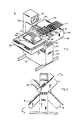
- FIGURE 1 shows a perspective view of the loader/unloader apparatus structured in accordance with the principles of the present invention,
- FIGURE 2 shows a front view of the loader/unloader apparatus depicted in Figure 1,
- FIGURE 3 shows a partial view of the loader/unloader apparatus of Figure 1 with portions thereof removed so as to disclose pertinent internal apparatus,
- FIGURE 4 shows a cross-section of the loader/unloader apparatus taken along line 4-4 of Figure 2 with portions thereof being removed or cut away so as to disclose pertinent portions of the apparatus,
- FIGURES 5A and 5B show a cross-section of a loader/unloader mechanism in the position for loading IC packages,
- FIGURE 6 shows a cross-section of the IC package delivery channel taken along line 6-6 in Figure 5A,
- FIGURE 7 shows an enlarged cross-section of the gate mechanism depicted in Figures 5A and 5B,
- FIGURES 8A and 8B show a cross-section of a loader/unloader mechanism when in the position for unloading IC packages,
- FIGURE 9A shows a partial cross-section of a loader/unloader mechanism configured for removing DIP's from a burn-in board,
- FIGURE 9B shows a partial cross-section of the loader/unloader mechanism of Figure 9A taken along
line 9B-9B of Figure 9A, - FIGURE 9C shows a partial cross-section of a portion of the loader/unloader mechanism depicted in Figures 9A and 9B taken along line 9C-9C of Figure 9B,
- FIGURE 10 shows a block diagram of a control system for the loader/unloader apparatus, and
- FIGURE 11 shows a partial cross-section of a portion of the loader/unloader apparatus configured for testing sockets on a burn-in board.
- "Burn-in" refers generally to the technique whereby integrated circuit (IC) packages are stressed, and sometimes tested, within their physical and electrical limits prior to their sale or distribution so that those packages likely to become early failures in complicated equipment can be discovered, and so that IC packages, in some cases, can be graded and sorted according to performance specifications. The burn-in technique generally includes loading the IC packages into sockets on burn-in boards, placing the burn-in boards in a chamber whose environment, particularly temperature, is controllable, applying electrical test signals to the boards while subjecting the IC packages to the maximum temperature reading therefor, removing the burn-in board from the chamber, and unloading the IC packages from the burn-in boards. In addition, it is sometimes desirable to sort the IC packages by performance grade after burn-in.
- Referring initially to Figure 1, there is shown a loader/
unloader apparatus 10 for automatically loading IC packages (not shown) intosockets 14 on one or more burn-inboards 16. Typical IC packages, as are referred to herein, are dual in-line packages ("DIP's"), which comprise a parallelepiped body portion having from four to sixty-four electrical leads of a generally L-shaped cross-section extending out and down from the opposing sides of the body. The overall width of the IC package may be, for example, 0.3, 0.4 or 0.6 inch (1 inch = 25.4 mm). Thesockets 14 mounted on the burn-inboards 16 include socket contacts defining slots for receiving electrical leads on IC packages. Alternatively, the IC package may be a surface mounted device ("chip") including small outline integrated circuits (SOIC's), plastic leaded chip carriers (PLCC's), ceramic leaded chip carriers (CLCC's), or leadless chip carriers (LCC's). The SOIC also comprises a generally parallelepiped body portion having electrical leads extending from opposing sides of the body. The electrical leads may have either a J-shaped or an S-shaped ("gull wing") cross-section permitting the lead to lie on the surface of thesocket 14 rather than being inserted into slots in the socket. The PLCC, CLCC, and LCC have bodies which are of a square or rectangular geometry with a relatively thin cross-section, giving these IC packages an overall wafer-shaped appearance. In the usual construction, the PLCC and the CLCC have mutliple electrical leads positioned flush with or bent into close proximity with the body of the package, while the LCC has conductive coatings applied at select areas on the major body surfaces. To accommodate surface mounted IC packages, thesockets 14 therefore include socket contacts having conductive coatings on the surface of the socket. - The loader/
unloader 10 shown in FIG. 1 may be used to load all types of IC packages on and unload them from burn-in boards. Additionally, the apparatus may be used to selectively unload, and thereby sort, chips after the burn-in process has been completed. - Referring still to FIG. 1, loader/
unloader apparatus 10 is shown in a commercial package and is comprised generally ofsupport structure 20 androtatable platform 30.Support structure 20 includes abase portion 22 for supportingplatform 30 and astanchion portion 24. Thesupport structure 20 comprises a frame (not shown) manufactured from structural tubing or other heavy gauge metal which is covered with sheet metal panels, such aspanel 28.Base portion 22 andstanchion portion 24 also enclose certain drive mechanisms and control apparatus hereafter described in greater detail. - Referring briefly to FIGS. 2 and 4,
platform 30 is generally comprised of left andright end panels front panel 36,rear panel 38, andbottom panel 40, these panels being bolted, welded or otherwise suitably fastened together at substantially right angles so as to form a box-like structure. Referring again to FIG. 1,canopy 42 is rigidly attached toright end panel 34,front panel 36 andrear panel 38 and extends approximately one-third the length ofplatform 30, thereby extending above a portion ofbottom panel 40 and forming a partial enclosure into which burn-inboards 16 may be positioned as described in greater detail below. Lateral cross bars 41 span the width ofplatform 30 and are spaced above burn-inboards 16 where they are rigidly affixed to front andrear panels unloader mechanism 140, also hereafter described in greater detail. - As can be seen most clearly in FIG. 4,
platform 30 is rotatable about anaxis 44 which extends generally perpendicular tofront panel 36 andrear panel 38.Platform 30 rotates aboutaxis 44 onfront shaft 46 andrear shaft 48.Shafts plates 49 which are then bolted tofront panel 36 andrear panel 38.Front shaft 46 is received through apertures infront panel 36 and in framing member 21 ofbase 22 and is supported by a flange-type bearing 51 which is bolted to framing member 21.Rear shaft 48 is received throughbushings 35, positioned in apertures inrear panel 38 and framingmember 23 ofbase 22, and is rigidly attached to drivesprocket 60. - Referring again to FIG. 2, loader/
unloader apparatus 10 is shown in loading position 11, i.e., the position in which loader/unloader mechanism 140 loads IC packages delivered from ICpackage storage tubes 17 into sockets mounted on burn-in-board 16. FIG. 2 also illustrates loader/unloader apparatus 10 in unloading position 13 (dashed line) in which loader/unloader mechanism 140 extracts IC packages from sockets on burn-inboard 16 and transports the packages tostorage tubes 17. - Referring now to FIG. 3, there is shown a partial rear view of the lower portion of
stanchion 24 ofsupport structure 20 with arear panel 28 removed, thereby revealing the drive apparatus used to rotateplatform 30. As shown, drivemotor 70 is affixed withinstanchion 24 in a vertical orientation.Motor shaft 68 is connected through coupling 67 to worm-gear 66 which engages the teeth ofdrive sprocket 60. Drivemotor 70, such as Model No. M092 manufactured by the Superior Electric Company is reversible. Upon receipt of the appropriate signal from a controller (not shown), such as a microprocessor hereafter described in greater detail, drivemotor 70 will turn worm-gear 66 and rotatedrive sprocket 60 in a clockwise direction as viewed in FIG. 3 so as to rotateplatform 30 into the loading position 11 depicted in FIG. 2. A potentiometer 302, mounted onfront shaft 46 withinsupport structure 20, shown in FIG. 4, sends a continuous analog voltage signal to the controller, thereby indicating the angular position ofplatform 30. On achieving the desired degree of rotation, which may be, for example, 35 degrees from the horizontal for loading certain sized chips and DIPs, the controller will stop drivemotor 70 and halt the rotation ofplatform 30. Upon receipt of another control signal from the controller, such as when loading has been completed,motor drive 70 andworm gear 66 will rotate drivesprocket 60 in the counter-clockwise direction as viewed in FIG. 3, and thereby rotateplatform 30 back to the horizontal position shown in FIG. 1 or to the unloading position 13 as depicted in FIG. 2. Potentiometer 302 is again employed to continuously signal the angular position ofplatform 30. - Referring again to FIG. 4, a section view of
platform 30, burn-inboard 16 is mounted on table 106, with portions of each cut-away to depicttable carriage 92 andtable shuttle 89; table 106,table carriage 92 andtable shuttle 89 all cooperatively interact to maneuver burn-inboard 16 andsockets 14 beneath the loader/unloader mechanisms 140, depicted in FIG. 1, as hereafter described. As shown in FIG. 4, affixed to endpanels platform 30 arebrackets 80 which rigidly supportcross members 82 abovebottom panel 40. Cylindricalcarriage support rods 84 are bolted to crossmembers 82, thereby forming a track on whichtable carriage 92, described below, may traverse in either the forward or rearward direction,arrows table carriage 92 is controlled bycarriage drive motor 86 which is secured to crossmember 82 nearest toright end panel 34. The shaft ofcarriage drive motor 86 is connected to a threaded cylindrical metallic rod or screw 90 which is supported at both ends thereof byscrew journal boxes 91, the left mostscrew journal box 91 being bolted toleft cross member 82 and rightscrew journal box 91 being secured to motor mounting bracket 88, which, in turn, is bolted toright cross member 82. -
Table carriage 92, slidably supported oncarriage support rods 84, includesrear runner 94,front runner 96,carriage support housings 97 andshuttle support rods 98.Rear runner 94 andfront runner 96 are generally L-shaped in cross section and include a vertical portion and a bottom flat portion to which a pair ofcarriage support housings 97 are attached. Thecarriage support housings 97 are slidably affixed tocarriage support rods 84,carriage support rods 84 passing through bushings contained therein, such as Thompson recirculating ball bushings.Shuttle support rods 98 extend between, and are rigidly attached to, the vertical portions ofrunners table shuttle 89 may traverse laterally in the direction denoted byarrows 111 and 113 in FIG. 4,table shuttle 89 providing support for and being affixed to table 106 by suitable fastening means such as bolts (not shown).Shuttle support rods 98 are slidably received through bushings in fourshuttle support housings 99 which are fastened to the sides ofshuttle 89, such bushings also typically being Thompson recirculating ball bushings. Lateral movement ofshuttle 89 and table 106 indirections 111 or 113 is initiated byshuttle drive motor 102 which is secured tofront runner 96. The shaft ofshuttle drive motor 102 is connected to a second threaded cylindrical metallic rod or screw 104 which passes through a threadedcoupling 103 attached to underside oftable shuttle 89. - In operation, table 106 and burn-in
board 16 are advanced in either theforward direction 108 orrearward direction 110 by means of the rotation ofscrew 90. Rotational motion of thescrew 90, generated by energizingcarriage drive motor 86, is translated to forward and rearward linear motion of table 106 by means of threadedcoupling 93 affixed to forwardshuttle support rod 98. Threads ofcoupling 93 cooperatively engage the threadlike groves extending continuously about the circumference ofscrew 90, causingtable carriage 92 to advance linearly asscrew 90 rotates. Similarly, table 106 and burn-inboard 16 are advanced in alateral direction 111 or 113 by means of the rotation ofscrew 104. Screw 104 passes through threadedcoupling 103 which is secured totable shuttle 89. Rotational motion ofscrew 104, generated by energizingshuttle drive motor 102, is translated into linear motion of table 106 by means of threadedcoupling 103 whose threads cooperatively engage the groves ofscrew 104, causing the table 106 to advance laterally in a direction perpendicular to the forward and rearward directions depicted byarrows - Burn-in
board 16 is removably affixed in a predetermined position to table 106 by suitable clamping means such as pneumatic actuated clamp 19 shown in FIG. 1.IC sockets 14 are arranged on the burn-inboard 16 in a substantially close fitting array comprised of rows which are aligned as indicated by the arrow at 112, and in columns which are aligned as indicated by the arrow at 114. As is evident from FIG. 4,IC sockets 14 aligned in a row are arranged side by side;IC sockets 14 aligned in a column are arranged end to end. The slidable nature of the attachment of the loader/unloader mechanisms 140 onto cross bars 41, shown best in FIG. 1, facilitate adjustment of the lateral position of the loader/unloader mechanisms 140 so as to accommodate a variety of sizes of burn-in boards having differing spacing between columns of sockets. - Referring now to FIGS. 1 and 4, loader/
unloader apparatus 10 includes a control system, hereinafter described in greater detail, which among other functions serves to direct the proper positioning of table 106 and burn-inboard 16 which respect to loader/unloader mechanisms 140 so as to align a column ofsockets 14 on burn-inboard 16 with each loader/unloader mechanism 140. As described above, positioning of table 106 and burn-inboard 16 is accomplished by controlling the operation ofcarriage drive motor 86 andshuttle drive motor 102. These motors are precisely controllable stepper motors whose direction of rotation is reversable and whose degree of rotation is accurately controlled according to step pulses generated by the controller. These drivemotors - The precise control achievable through the use of such motors translates into equally precise control of the position of table 106. Accordingly, the present invention does not require the use of a series of position sensors. Instead, the controller utilized in loader/
unloader apparatus 10 only requires sensors to indicate whentable carriage 92 andtable shuttle 89 are in their starting or "home" positions. Upon receipt of signals indicating thattable carriage 92 andtable carriage 89 are in their respective home positions, the controller can drivecarriage 92 andshuttle 89 to the proper starting position for loading or unloading IC packages on burn-inboard 16, the exact positioning of which will depend upon a variety of factors, such as the number and size of burn-in boards and the size and type of IC packages to be handled. - The position sensors employed by the present invention are best shown in FIG. 4. As shown,
support rod 130 is affixed tobottom panel 40 parallel to supportrods 84 bybracket 131. Affixed to supportrod 130 arephotoelectric sensors rear runner 94 oftable carriage 92. Indicator 134 andphotoelectric sensors table carriage 92 moves linearly in forward orrearward direction Photoelectric sensor 132 signals the limit of travel in therearward direction 110 and signals the home position in the forward and rearward directions for each loading or unloading sequence. While the movement and position oftable carriage 92 is precisely controlled through the use of a stepper drive motor as described above,photoelectric sensor 133 serves as a back-up or safety device to limit forward travel oftable carriage 92 should a control malfunction occur. Similarly,photoelectric sensor 135, which may also be model no CLI-355, manufactured by the Clairex Electronics Company, is mounted ontable shuttle 89 and positioned so as to receiveindicator 136 which is attached to and extends fromforward runner 96.Photoelectric sensor 135 signals the limit of travel oftable shuttle 89 in thelateral direction 113 and signals the home position in the lateral direction for any loading or unloading sequence. - FIG. 10 shows a block diagram disclosing the basic organization of the control system for the loader/
unloader apparatus 10. The control system is centered around amicroprocessor 300, such as Model No. 2003XC manufactured by Texas Microsystems, Inc. Themicroprocessor 300 is housed insupport structure 20. - The loader/
unloader apparatus 10 includes afront control panel 25, shown also in FIG. 1, having a plurality of push buttons arranged thereon for an operator to enter set-up parameters and to command certain operations of the loader/unloader apparatus 10. The commands which may be communicated by an operator throughcontrol panel 25 to themicroprocessor 300 include start, stop, run, and step commands. Certain tests of loader/unloader apparatus 10 may also be initiated fromcontrol panel 25.Floppy disk drive 27, supported inbase structure 22, provides a means through which to input operating instructions and data tomicroprocessor 300. Input and output messages are communicated to the operator viamonitor 26 which is supported by and housed instanchion 24 as shown in FIG. 1. - In addition to the
control panel 25,disk drive 27, and monitor 26, the control system comprises additional input and output subsystems. The firstadditional input subsystem 310 is for communicating the angular position ofplatform 30 and comprises potentiometer 302, shown in FIG. 4, which continuously transmits an analog voltage signal tomicroprocessor 300 indicating the angular position ofplatform 30. Anoutput subsystem 318 is provided to start and stopplatform drive motor 70 as required for the various IC package loading, unloading, and sorting functions to be performed by loader/unloader apparatus 10. - Input subsystems 312, 314, and 316 are also provided for receiving signals from
photoelectric sensors platform 30 as shown in FIG. 4. As explained above,photoelectric sensors platform 30. In response to signals fromphotoelectric sensors output subsystems microprocessor 300 operatescarriage motor 86 andshuttle drive motor 102 to advance table 106 and burn-inboard 16 in the forward, rearward, and lateral directions so as to position the proper row and column of sockets beneath the loader/unloader mechanisms 140. Input subsystem 134, includingphotoelectric sensor 133 is provided to signalmicroprocessor 300 should the carriage drive control system malfunction, allowingtable carriage 92, shown in FIG. 4, to advance too far in theforward direction 108. - The control system for loader/
unloader apparatus 10 also includes avacuum source subsystem 324 which includes hardware by whichmicroprocessor 300 controls actuation of pick-upheads 210 of loader/unloader mechanisms 140 as hereafter described in greater detail. Avacuum subsystem sensor 326 is provided to monitor the vacuum generated and available at the pick-up heads of loader/unloader mechanisms 140 so as to provide an input signal tomicroprocessor 300 indicating whether a particular loader/unloader mechanism 140 has successfully lifted an IC package by means of the vacuum generated and supplied to that loader/unloader mechanism 140. - Also included in the control system for loader/
unloader apparatus 10 is apneumatic source subsystem 330 which includes hardware by whichmicroprocessor 300 controls actuation of clamp 19 and actuation ofair cylinders unloader mechanism 140, hereafter described in greater detail. - The control system finally includes a
socket test subsystem 328.Socket test subsystem 328, including test-heads 400 hereinafter described in greater detail, is used to transmit test signals to, and record the response from, sockets which are to be loaded with IC packages for burn-in. By testing sockets before loading, defective sockets can be identified and their location recorded bymicroprocessor 300. During the loading process then, IC packages will not be inserted into the defective sockets. - Loader/
unloader mechanism 140 is employed to load and unload all types of IC packages, namely both chips and DIP's. The loading sequence for both types of IC packages is identical although slight modifications to the loader/unloader mechanism 140 are made to accommodate the physical differences between chips and DIP's. The loading sequence for IC packages will be described with reference to FIGS. 5A, 5B, 6 and 7 which depict loading of chips. The modifications to loader/unloader mechanism 140 required for loading DIP's will be noted. The unloading of chips is described with reference to FIGS. 8A and 8B. The modifications to loader/unloader mechanism 140 required to unload DIP's from sockets on a burn-in board are described with reference to FIGS. 9A, 9B and 9C. - Referring now to FIG. 5A, one of a plurality of loader/
unloader mechanisms 140 is shown in cross section while in the loading position. Loader/unloader mechanism 140 generally includestransport device 150,gate mechanism 170, anddelivery channel 190. Due to the force of gravity, whenplatform 30 is in the loading position,delivery channel 190 provides a steady supply ofIC packages 12 in serial fashion to thetransport device 150 for insertion intosockets 14 on burn-inboard 16.Gate mechanism 170 ensures that the IC packages 12 advance to transportdevice 150 one IC package at a time. -
Delivery device 190 includestrack 192,track cover 194 andtrack base 196. Referring now to FIGS. 5A and 6,track 192 includes achannel 193 in which IC packages 12 may slide. The width ofchannel 193 is dependent upon the width of the IC package then being loaded, the width ofchannel 193 being only slightly wider thanIC package 12, so as to insure the proper orientation and position of the IC package.Transport device 150 picks upIC package 12 fromdelivery track 192 and loads it on burn-inboard 16. -
Track 192 is configured differently when loader/unloader mechanism 140 loads DIPs rather than chips on a burn-in board. Instead of having achannel 193 formed therein, track 192 instead is formed with a ridge, generally rectangular in cross section and having a width slightly less than the distance between the rows of leads extending from the DIP, allowing the DIP to straddle and slide upon the ridge. - Referring still to FIGS. 5A and 6, in either configuration,
track 192 is attached to trackbase 196 by recessedscrews 198.Track base 196 also includespins 199 and a capturedcap screw 200 forfastening track base 196 to supportplate 43, which in turn is clamped to lateral cross bars 41. Ascap screw 200 is the sole means for attachingdelivery channel 190 and loader/unloader mechanism 140 toplatform 30, loader/unloader mechanisms 140 can be quickly and easily changed when it is desirable to load or unload a different size or type of IC package than those previously handled.Track base 196 includesconduits 249 formed therein for connection topneumatic hoses 250 which control the operation oftransport mechanism 150, as explained below.Track cover 194, L-shaped in cross section, includes aside plate 195 andtop plate 197 and is attached to track 192 by screws throughside plate 195.Top plate 197 retains IC packages 12 in position intrack 192 as the packages are fed towardgate mechanism 170 by the force of gravity. - As shown in FIG. 5A,
gate mechanism 170 is attached totop plate 197 oftrack cover 194.Gate mechanism 170, best shown in FIG. 7, includesenclosure 172,gate rod 184, left and right gate pins 180 and 182 respectively, bushing blocks 174 and support blocks 183. Referring to FIG. 7,enclosure 172 is generally box-like in configuration and is fastened to trackcover 194 through bushing blocks 174 by spring loaded fasteners 176. Bushing blocks 174 are secured toenclosure 172 by flush mounted fasteners (not shown). The male portion of spring loaded fasteners 176 are recessed withintop plate 197 oftrack cover 194 so as not to impede the flow of IC packages 12 alongtrack 192.Gate rod 184 passes throughenclosure 172 and is slidably received within coaxially aligned apertures in bushing blocks 174 allowing reciprocal motion ofgate rod 184 therethrough. Left and right gate pins 180 and 182 are retained in position withinenclosure 172 bysupport blocks 183 which are secured toenclosure 172 by flush mounted screws on other suitable fasteners (not shown), the gate pins 180 and 182 being separated by a distance greater than the length of the IC package being handled, that distance typically approximating one and one-half times the length of the IC package. - Gate pins 180 and 182 are interally threaded and fitted with a short length of
rubber tubing 181 which is retained within the threaded portion of gate pins 180 and 182 through compression fit. Anindentation 186 is formed ongate rod 184 so that asrod 184 reciprocates withinenclosure 172,indentation 186 moves between positions aboveleft gate pin 180 and aboveright gate pin 182. Asindentation 186 moves above eithergate pin spring 185 forces the respective gate pin upward where it is captured byindentation 186. Asgate rod 184 reciprocates further andindentation 186 moves correspondingly,indentation 186 cams the capturedgate pin tubing 181 protrudes through holes or slots formed intop plate 197 oftrack cover 194. With only oneindentation 186 formed ongate rod 184,tubing 181 of one or both of gate pins 180 and 182 will extend throughtop plate 197 of track cover of 194 at all times. The length of gate pins 180 and 182 and oftubing 181 are of such dimensions so as to ensure thattubing 181 will impede the flow of IC packages alongdelivery channel 190 when gate pins 180 and 182 are not captured byindentation 186 ofgate rod 184. Hereinafter, a reference to gate pins 180 and 182 shall refer to the entire gate pin assembly comprising both the screw portion and the length of tubing, it being understood thatonly tubing 181 actually extends intodelivery channel 190. - Referring again to FIG. 5A,
transport device 150 includes a vacuum actuatedpickup head 210, slide block 212,vertical air cylinder 214,horizontal air cylinder 216,adjustable stops 218, front andrear face plates 224 and 226 respectively, and end plate 228 (front face plate shown in FIGS. 1 and 2). Front andrear face plates 224 and 226 are attached todelivery channel 190 by flush mountedbolts 205. Front andrear face plates 224 and 226 are also fastened toend plate 228 and spacer block 229 by suitable flush mounted fasteners (not shown). One end ofhorizontal cylinder 216 threadedly engages spacer block 229.Piston rod 221 extending fromhorizontal cylinder 216 is slidably received through an aperture formed in spacer block 229 and threadedly engages slide block 212. Slide block 212 is disposed between front plate 224 andrear plate 226. Guide pins 230 extend from slide block 212 at substantially right angles to the parallel planes formed by front face plate 224 andrear face plate 226, guide pins 230 being received withinslots 227 formed inface plates 224 and 226, thereby supporting slide block 212 aspiston rod 221 reciprocates withinhorizontal cylinder 216.Vertical cylinder 214 is threadedly engaged to the top of slide block 212.Piston rod 220 extending fromvertical cylinder 214 is slidably received through an aperture formed in slide block 212 and threadedly engages vacuum actuated pick-uphead 210. - Pick-up
head 210, a metalic block, includes an internal conduit (not shown) one end of which terminates at the lower surface 211 of pick-uphead 210, surface 211 forming the surface against which IC packages are secured during transport by a vacuum source which is connected to the other end of the internal conduit by a vacuum line or hose (not shown). The vacuum line passes throughopening 234 formed inrear plat 226, opening 234 permitting the horizontal and vertical movement the vacuum line aspiston rods head 210. As depicted in FIG. 5A,horizontal cylinder 216 includespiston rod 222 extending from the rearward end ofcylinder 216,piston rod 222 threadedly engaging one end ofconnection bar 204. The opposite end ofconnection bar 204 is slotted so as to receivegate rod 184 and permit reciprocation therethrough. In this configuration, aspiston rod 222 reciprocates withinhorizontal cylinder 216,connection bar 204 slides alonggate rod 184 unimpeded until engagingcollars gate rod 184 by set screws or other suitable means (not shown). Aspiston rod 222 continues to travel afterconnection bar 204 has engaged eithercollar gate rod 184 actuatesgate mechanism 170 as hereinafter explained in more detail. - Before initiating the loading sequence of loader/
unloader 10, an operator inserts the open end of an ICpackage storage tube 17 to eachdelivery channel 190 by clampingdevice 191 as depicted in FIG. 1. The operator additionally places a burn-inboard 16 to table 106. The operator then depresses the "run" pushbutton onconsole 25 which first actuates pneumatic clamp 19, securing the burn-in board to table 106, andnext rotates platform 30 into the loading position 11 as depicted in FIG. 2, withplatform 30 sloping from right to left at an incline, for example, of approximately 35 degrees. Depending upon the size and mass of the particular IC packages being loaded, the loading angle may be lesser or greater than 35 degrees. The angle of incline must be steep enough to ensure the packages will properly feed throughdelivery channel 190, but not be so steep that the packages could be damaged as they slide fromstorage tubes 17 until thefrontmost IC package 50 comes to rest withingate mechanism 170 as depicted in FIG. 5A. - Referring now to FIG. 5A, as
platform 30 rotates from a substantially horizontal position shown in FIG. 1, to the loading position 11 as shown in FIG. 2, the IC packages 12 maintained in thestorage tubes 17 slide intotrack 192 ofdelivery channel 190 due entirely to the force of gravity.Vertical cylinder 214 is initially positioned as shown in FIG. 5A withpiston rod 220 completely retracted such that pick-uphead 210 is in its uppermost position. Because of the interconnection betweenvertical piston 214, slide block 212, andpiston rod 221, withvertical cylinder 214 in its initial position,piston rod 222 ofhorizontal cylinder 216 is fully extended, which when achieving that position causedconnection bar 204 to contact and push againstcollar 203, thereby positioningindentation 186 ofgate rod 184 aboveright gate pin 182. Against the action ofsprings 185,right gate pin 182 is captured by theindentation 186 ofgate rod 184 so as not to extend intodelivery channel 190. By contrast, leftgate pin 180 is pressed downward bygate rod 184 so as to extend through the hole intrack cover 194 and impede the flow of IC packages alongdelivery track 192. Thus, asplatform 30 is rotated into the loading position, IC packages 12 continue to slide towardstransport device 150 until thefrontmost IC package 50 engages leftgate pin 180. - Before
controller 300 initiates the loading of IC packages 12 bytransport mechanism 150, burn-inboard 16 must be properly positioned withinplatform 30. Accordingly, as best shown in FIG. 4,controller 300 initiates travel oftable carriage 92 in therearward direction 110. Asleft runner 94 oftable carriage 92 moves in therearward direction 110, downwardly extending indicator 134 passes within the channel formed in the upper surface ofphotoelectric sensor 132 which then signalscontroller 300 that tablecarriage 92 is in the home or start position. Sequentially or simultaneously,controller 300 signalslateral drive motor 102 to drivetable shuttle 89 in thelateral direction 113 untilindicator 136 triggersphotoelectric sensor 135signaling controller 300 that shuttle 89 is in its home position. Having already received input signals via the floppy disk placed indisk drive 27 or from the operator'scontrol panel 25 instructingcontroller 300 as to the size and number of burn-inboards 16, the size of the IC packages 12, and the spacing ofsockets 14 on burn-inboards 16 positioned on table 106 and other such variables,controller 300 will activate drivemotors sockets 14 on burn-inboard 16 directly below pickup heads 210 of loader/unloader mechanisms 140. It should be understood that the positioning of table 106 and burn-inboard 16 may be accomplished before, during, or afterplatform 30 has been rotated into the loading position 11. - Except in the instance when a malfunction has been detected, loader/
unloader mechanisms 140 will all operate in unison, thereby loading a number of sockets in a row simultaneously. Accordingly, the loading operation is understood by referring to and depicting a single loader/unloader mechanism 140 as depicted in FIG. 5A. - Referring first to FIG. 5A, when the
first IC socket 14 is positioned beneath pick-uphead 210 of loader/unloader mechanism 140,controller 300 actuateshorizontal cylinder 216 so as to extendpiston rod 221, retractpiston rod 222, and thereby move slide block 212 andvertical cylinder 214 to the position shown in FIG. 5B. Aspiston rod 221 is being extended,connection bar 204 slides alonggate rod 184 until engagingcollar 202. Referring again to FIG. 5A, aspiston rod 221 continues its stroke,connection bar 204 pushes againstcollar 202 which pushesgate rod 184 untilindentation 186 is no longer located aboveright gate pin 182,gate rod 184 thereby forcingright gate pin 182 through the aperture intop plate 197 oftrack cover 194 and pinning theIC package 51 withindelivery channel 190 and preventing it from sliding further alongtrack 192.Gate rod 184 continues to be pushed intoenclosure 172 untilpiston rod 221 completes its stroke, at whichtime indentation 186 is located directly aboveleft gate pin 180, allowingleft gate pin 182 to clear itself fromtop plate 197 oftrack cover 194, thereby permitting thefrontmost IC package 50 to slide downtrack 192 until it contacts and comes to rest againststop post 206, shown asIC package 50′ in dashed lines in FIG. 5A. - After a timed interval, a second control signal generated by
controller 300 actuateshorizontal cylinder 216 and causes slide block 212 andvertical cylinder 214 to return to their initial positions shown in FIG. 5A such that pick-uphead 210 is now positioned directly aboveIC package 50′ now positioned againststop post 206. As this occurs,piston rod 222 is extended, causingconnection bar 204 to slide alonggate rod 184 until it engagesrear collar 203 and drawsgate rod 184 out ofenclosure 172, which in turn causesleft gate pin 180 to be cammed downward forcing it throughtop plate 197 oftrack cover 194 and intodelivery channel 190. Asgate rod 184 continues its rearward motion,indentation 186 slides aboveright gate pin 182.Spring 185forces gate pin 182 upward and out ofdelivery channel 190 and thus out of contact withIC package 51, allowing IC packages 51 and 52 and all serially positioned packages to slide downward alongtrack 192 one package length such thatIC package 51 engages and comes to rest in the position previously vacated byIC package 50′ against now extendedleft guide pin 180,IC package 52 coming to rest beneathright gate pin 182 in the position just vacated byIC package 51. Again, after a timed interval,controller 300 actuatesvertical cylinder 214 and extendspiston rod 220 andpickup head 210 downward untilpickup head 210 is in close proximity to the top ofIC package 50′.Controller 300 then actuates the vacuum source attached to pick-uphead 210 and secures the top ofIC package 50′ against the bottom ofpickup head 210. After a vacuum sensor has confirmed thatIC package 50′ has been picked-up,vertical cylinder 214 is actuated so thatpiston rod 220 is retracted. - Referring now to FIG. 5B, after a predetermined interval,
horizontal cylinder 216 is then actuated, sending slide block 212 andvertical cylinder 214 to its frontmost position,IC package 50′ held securely by pick-uphead 210. As this occurs, theindentation 186 inguide rod 184 once again moves to a position aboveleft gate pin 180 which causesright gate pin 182 to be forced downward intodelivery channel 190 and to press against and therebysecure IC package 52 beneath it intrack 192. Asindentation 186 move aboveleft gate pin 180, the force supplied byspring 185 retracts leftgate pin 180 fromtrack cover 194, allowingIC package 51 to slide downdelivery channel 190 until engagingpost 206 as shown in FIG. 5B. Still referring to FIG. 5B, after a timed interval,vertical cylinder 214 is actuated andpiston rod 220 andpickup head 210 then move to their lower- most positions (dashed lines) andIC package 50 is positioned insocket 14, at whichtime controller 300 deactivates the vacuum supply topickup head 210 and retractspiston 220 and pick-uphead 210 to their uppermost position as shown in FIG. 5B. Burn-inboard 16 is then propelled in theforward direction 108 as previously described, until the second row of sockets are aligned beneath thepickup head 210. - In a like manner, burn-in
board 16 is driven forward after sockets in each row have passed beneath pick-uphead 210 until sockets in the final row of burn-in board orboards 16 have been loaded. At this time, a number of columns of sockets have been loaded, that number dependent upon and equal to the number of loader/unloader mechanisms 140 affixed toplatform 30. At this time,table shuttle 89 is propelled in thelateral direction 113 as shown in FIG. 4 so as to align columns of empty sockets with loader/unloader mechanisms 140. Theempty sockets 14 which are now positioned beneath pick-upheads 210 are loaded as described above. Burn-inboard 16 is then propelled in arearward direction 110 in a step-wise fashion so as to complete the loading of the columns of sockets now aligned with loader/unloader mechanisms 140. After loading IC packages into the last sockets in those columns,table shuttle 89 once again propels burn-inboard 16 laterally indirection 113 so as to align additional columns of empty sockets with loader/unloader mechanisms 140. Thus, in this serpentine manner, all of the sockets on one or more burn-inboards 16 may be loaded. - On each occasion in which pick-up
head 210 is employed to lift an IC package for transport, avacuum sensor 326 depicted in the control diagram of FIG. 10, monitors the vacuum present at pick-uphead 210 to determine whether an IC package has been lifted for transport. Whenvacuum sensor 326 detects that pick-uphead 210 has not been successful in lifting an IC package,microprocessor 300 directs the following remedial procedures. In operation,vertical piston 214 is actuated so as to raise pick-uphead 210 before thevacuum sensor 326 makes its first check. Ifvacuum sensor 326 signals that an IC package has not been lifted,vertical piston 214 is again actuated so as to extendpiston rod 220 and pick-uphead 210 to their lowermost positions. After the standard timed interval, vacuum is again applied to pick-uphead 210 andvertical piston 214 is then actuated so as to raise pick-uphead 210. At this time, a second test is made byvacuum sensor 326. If it is again determined that the IC package has not been lifted, a second remedial procedure is followed wherebyhorizontal cylinder 216 is actuated so as to first transportvertical piston 214 and pick-uphead 210 to their position shown in FIG. 5B.Horizontal cylinder 216 is then actuated so as to return pick-uphead 210 andvertical cylinder 214 to the position shown in FIG. 5A, this two-step process actuatinggate mechanism 170 so as to deliver anotherIC package 12 againststop post 206. Pick-uphead 210 is then driven downward towardIC package 12, the vacuum is applied, and pick-uphead 210 is once again raised. In this position,vacuum sensor 326 again checks to determine whether an IC package has been lifted. Ifvacuum sensor 326 again determines that no IC package has been lifted by pick-uphead 210, an error message is transmitted to the operator viamonitor 26, and loading then ceases. While these checks and remedial procedures are being conducted, the positioning of burn-inboard 16 and table 106 is maintained, and, except for the loader/unloader mechanism 140 involved in the procedures described, the remainder of the loader/unloader mechanisms 140 remain idle. - In the unloading mode, the loader/
unloader mechanism 140 operates in substantially the same manner as when it loads IC packages onto burn-in boards, the only significant difference being that in the unloading sequence, thetransport mechanism 150 removes IC packages from sockets on one or more burn-in boards and returns them todelivery channel 190 which, due to the force of gravity, delivers the IC packages to ICpackage storage tubes 17 after they pass throughgate mechanism 170. Because of the similarity between the loading and unloading sequence, a brief description of the unloading sequences for both chips or DIP's are sufficient to enable one skilled in the art to understand and appreciate the unloading operation as performed by the present invention. - Referring first to FIGS. 1 and 2, after an operator has secured the loaded burn-in
boards 16 to table 106,platform 30 is rotated to the unloading position 13 as depicted in dashed lines in FIG. 2.Table carriage 92 andtable shuttle 89 are then driven to their home positions bycontroller 300. Once the home positions are signaled, table 106 is then driven to the proper unloading position withinplatform 30, that position depending upon the number and size of burn-in boards, the size and type of IC packages to be unloaded and similar variables which have been input tocontroller 300 through operator'spanel 25 ordisk drive 27. It should be understood that, once again, positioning of table 106 may be accomplished either before, after, or during rotation ofplatform 30. - A brief description of the unloading sequence for chips will now be supplied. Referring now to FIG. 8A, once the
first socket 14 having achip 50 secured therein is positioned beneath pick-uphead 210,controller 300 actuatesvertical cylinder 214, thereby extendingpiston rod 220 and pick-uphead 210 untilpiston head 210 is in close proximity to chip 50, at whichtime controller 300 initiates the vacuum to pick-uphead 210 thereby liftingchip 50 fromsocket 14. Once a vacuum sensor (not shown) has determined that pick-uphead 210 has successfully removedchip 50,vertical piston 214 is actuated so as to retractpiston rod 220, thereby raising pick-uphead 210 to its uppermost position. After a timed interval,horizontal cylinder 216 is actuated so as to retractpiston rod 221 and extendrod 222 which, through the interaction ofconnection bar 204,collar 203, andgate mechanism 170, forces leftgate pin 180 intodelivery channel 190 as shown in FIG. 8B.Vertical cylinder 214 is then actuated so as to extendpiston rod 220 and lower pick-uphead 210 andchip 50 as shown in dashed lines in FIG. 8B. Whenchip 50 is ondelivery track 192, the vacuum to pick-uphead 210 is discontinued. Pick-uphead 210 is then raised, therby releasingIC package 50′ and allowing it to slide alongtrack 192 until it engages and comes to rest againstleft gate pin 180. After a timed interval,vertical cylinder 214 is again actuated so as to retractpiston rod 220 and lift pick-uphead 210. Whenhorizontal piston 216 is then actuated so as to extendpiston rod 221 and transport pick-up head andvertical piston 214 back to their positions shown in FIG. 8A,right gate pin 182 is then extended intodelivery channel 192, and leftgate pin 180 clears itself fromchannel 192, thereby releasingchip 50 which slides downdelivery channel 190 towardstorage tube 17 until coming to rest against now extendedright gate pin 182 as shown in dashed lines asIC package 50′ in FIG. 8A. After thenext IC package 51 has been removed from its socket by activation ofvertical cylinder 214 as described above,horizontal cylinder 216 will once again be actuated thereby extendingpiston rod 222 and thereby actuatinggate mechanism 170 such thatright gate pin 182 is retracted allowingchip 50′ to slide towards and into the IC package storage tube 17 (not shown) and such that leftgate pin 180 is extended intodelivery channel 192 so as to impede the progress of the next chip, once that chip has been released from pick-uphead 210. In this manner, chips are removed from sockets on burn-in boards and delivered back into IC package storage tubes, one chip at a time. - Although the procedure described may be employed to remove all the chips from sockets on the burn-in board simply in the order in which the socket are positioned beneath loader/
unloader mechanism 140, the procedure outlined above may also be used to selectively unload and thereby sort chips according to performance ratings or grades exhibited by the chips during the burn-in process. Frequently during burn-in, the chips' performance is monitored and compared against certain industrial standards established for such performance. The performance for each chip may also be recorded, for example on a floppy disk, such that the performance record may then be employed after burn-in to sort the chips according to their performance grades. This sorting process is frequently desirable so that chips having like performance grades may be packaged and sold to customers desiring the assurance that all the chips purchased meet the performance specification for a particular application. - The loader/
unloader apparatus 10 of the present invention is adapted for this sorting process. In practice, performance data on each chip which has undergone burn-in is input intomicroprocessor 300 throughdisk drive 27 as shown in FIG. 1, along with information conveying each chip's location on the burn-inboard 16. With such information,microprocessor 300 will selectively activate loader/unloader mechanisms 140 as the burn-in board is moved in its serpentine fashion beneath pick-upheads 210, thereby enabling chips having like performance grades to be sorted and packaged together instorage tubes 17 shown in FIG. 1. - The sequence for unloading DIP's is indentical to that described above for unloading chips; however,
transport mechanism 150 is modified somewhat as hereinafter described. Because DIPS are secured within sockets due to frictional forces acting upon the leads which extend from the body portion of the DIP, the vacuum force supplied to pick-uphead 210 for lifting and transporting chips is not alone sufficient to overcome those frictional forces and thereby remove the DIP from its socket. Accordingly,transport mechanism 150 is modified so as to includewedge member 250 andspacer block 252, spacer block 252 employed to attachwedge member 250 to the underside ofdelivery channel 192. Referring to FIGS. 9A, 9B, and 9C,wedge member 250 generally comprises a flattop portion 254 and akeel portion 256 rigidly affixed to the top portion at substantially a right angle such that thewedge member 250 has a "T-shaped" cross-section when a section is taken through the flattop portion 254. The width oftop portion 254 narrows until it equals the thickness ofkeel portion 256 at 255, best shown in FIG. 9C.Wedge member 250 is tapered at angle of approximately 7 degrees from shoulder 258 to the end ofwedge member 250, forming atapered blade 260 ending in apoint 262 at its foremost end, the end furthest fromspacer block 252.Tapered blade 260 has the dimensions x and y shown in FIG. 9C where dimension x is approximately equal to 0.85 inches and dimension y is approximately equal to 0.46 inches. The height ofwedge member 250 as measured at its untapered or highest point, "z" as shown in FIG. 9C is dictated by the size of the DIP, dimension z being slightly greater than the depth of the groove formed insocket 14. - As shown in FIG. 9A, as table 106 and burn-in
board 16 is moved towardtransport device 150 in theforward direction 108, the frontmost or leadingDIP 55 insocket 14 moves overpoint 260 and straddles the taperedblade 260 ofwedge member 250. As table 106 continues to move forward, the leading edge ofDIP 55 is raised or cammed upward by the action of its forward motion along thetappered blade 260. As table 106 and burn-inboard 16 continue their forward motion so as to positionDIP 55 directly beneath pick-uphead 210, shoulder 258 ofwedge member 250 moves underDIP 55 to a position approximately at the midpoint ofDIP 55. By this time,DIP 56 has moved over and now straddles the foremost end of the taperedblade 260 ofwedge member 250. While in this position,vertical cylinder 214 is actuated so as to extendpiston rod 220 and pick-uphead 210 toward their lowermost positions. With the right or leading end ofDIP 55 pried fromsocket 14 to a greater extent that its left or trailing end by taperedblade 260, pick-uphead 210 first contacts the leading end ofDIP 55. Aspiston 220 continues its downward stroke, the force of pick-uphead 210 against the leading end ofDIP 55 extracts the left or trailing end ofDIP 55 such that the upper surface ofDIP 50 is now substantially parallel to the lower surface of pick-uphead 210 and such that both ends ofDIP 55 are extracted fromsocket 14 to an equal extent. It should be understood, however, that at thispoint DIP 50 is still secured withinsocket 14 by frictional forces. In this position, the vacuum to pick-uphead 210 is actuated, the vacuum force now being sufficient to extractDIP 55 entirely from itssocket 14.Cylinders DIP 55 to thedelivery channel 190 in the same manner as chips are transported from burn-inboard 16 todelivery channel 190 as described above. - The present invention is also adaptable for use in performing functional tests on sockets mounted on burn-in boards so as to ensure that if an IC package is loaded into the socket, the package will be properly exercised when it undergoes the burn-in process previously described.
- In the testing configuration,
platform 30 is maintained in the horizontal position shown in FIG. 1. Test-head 400, shown in FIG. 11, threadedly engagespiston rod 410 extending from a vertically mounted air cylinder (not shown), the air cylinder being supported by a support bracket (not shown) which is clamped to lateral cross bars 41. Test-head 400 comprises abody portion 402 and a plurality ofelectrical leads 404 for making electrical connection with the electrical contacts in the IC socket to be tested.Leads 404 are electrically connected with in test-head 400 toconductors 406 which communicate electrical signals between the IC sockets to be tested andmicroprocessor 300. - In the testing mode, test-
head 400 is positioned above burn-inboard 16 over the first row ofsockets 14 to be tested.Microprocessor 300 then actuates the air cylinder so as to extendpiston rod 410 to its fully extended position, leads 404 thereby making electrical contact with the electrical contacts insocket 14. As should be apparent, test-heads 400 may differ in number of contacts and contact configuration in accordance with the type, size and configuration of socket being tested. - Once sockets in the first row on burn-in
board 16 have been tested and their test performance recorded bymicroprocessor 300, table 106 is advanced, in this example, in theforward direction 108 bytable carriage 92 so as to bring sockets in the next row on burn-inboard 16 beneath test-head 400. In this stepwise fashion previously described, all the sockets on the burn-in board may be tested.
Claims (9)
- An apparatus for loading IC packages (12) into and unloading IC packages (12) from sockets (14) mounted on printed circuit boards (16), comprising a support (30) for supporting the printed circuit boards (16) in a horizontal position, a transport device (140) affixed to said support (30) for inserting IC packages (12) into and extracting IC packages (12) from sockets (14) on said printed circuit boards (16), and a delivery device (190) affixed to said transport device (140) for delivering IC packages (12) to and from said transport device (140),
characterised in that said support (30) is rotatable from the horizontal in a first direction to convey the IC packages (12) by gravity from a storage position to the transport device (140) and rotatable from the horizontal in a second direction opposite the first direction to convey the IC packages (12) by gravity from the transport device (140) to the storage position. - An apparatus as claimed in claim 1, characterised by a positioning device (106) for positioning the printed circuit boards (16) beneath said transport device (140).
- An apparatus as claimed in claim 1, characterised by a control system (300) for receiving input signals from and communicating output signals to said apparatus.
- An apparatus as claimed in claim 1, characterised in that said delivery device (190) comprises a delivery track (192) for delivering IC packages (12) to and from said transport device (140) in a serial fashion.
- An apparatus as claimed in claim 4, characterised in that said delivery device (190) includes a gate mechanism (170) for delivering IC packages (12) to and from said transport device (140), one IC package (12) at a time.
- An apparatus as claimed in any one of claims 1 to 5, characterised in that said transport device (140) comprises a vacuum source (324), a pick-up head (210) actuatable by said vacuum source (324) for lifting IC packages (12), a first cylinder assembly (214) having a piston rod extending therefrom attached to said pick-up head (210) so as to lower said pick-up head (210) to a position in close proximity of an IC package (12) and to raise the IC package (12) after said pick-up head (210) has been actuated by said vacuum source (324), and a second cylinder assembly (216) having a piston rod extending therefrom and affixed to said first cylinder assembly (214) so as to move said first cylinder assembly (214) and said pick-up head (210) alternately between a position above said delivery device (190) and a position above the printed circuit boards (16).
- An apparatus as claimed in claim 6 when appended to claim 3, characterised in that said control system (300) includes a detector (326) for monitoring the vacuum at said pick-up head (210) so as to determine when an IC package (12) has been secured to said transport device (140) by actuation of said vacuum source (324).
- An apparatus as claimed in any one of claims 1 to 7, characterised in that said support (30) comprises a rotatable platform (30), and in that a table (106) is provided which is movably affixed to said platform (30) for supporting the boards (16), said table (106) being movable in the forward, rearward, and lateral directions.
- An apparatus as claimed in claim 8, characterised in that said delivery device (190) includes a clamping device (191) for securing an IC package storage tube to said delivery track (192) so as to allow IC packages (12) to slide between said delivery track (192) and the IC package storage tubes.
Applications Claiming Priority (2)
| Application Number | Priority Date | Filing Date | Title |
|---|---|---|---|
| US07/044,873 US4817273A (en) | 1987-04-30 | 1987-04-30 | Burn-in board loader and unloader |
| US44873 | 1987-04-30 |
Publications (2)
| Publication Number | Publication Date |
|---|---|
| EP0291144A1 EP0291144A1 (en) | 1988-11-17 |
| EP0291144B1 true EP0291144B1 (en) | 1992-05-20 |
Family
ID=21934792
Family Applications (1)
| Application Number | Title | Priority Date | Filing Date |
|---|---|---|---|
| EP88300559A Expired - Lifetime EP0291144B1 (en) | 1987-04-30 | 1988-01-25 | Burn-in board loader and unloader |
Country Status (5)
| Country | Link |
|---|---|
| US (1) | US4817273A (en) |
| EP (1) | EP0291144B1 (en) |
| JP (1) | JPH0715494B2 (en) |
| DE (1) | DE3871229D1 (en) |
| SG (1) | SG92792G (en) |
Families Citing this family (65)
| Publication number | Priority date | Publication date | Assignee | Title |
|---|---|---|---|---|
| JPH0725721Y2 (en) * | 1987-09-08 | 1995-06-07 | 岡谷電機産業株式会社 | Loader / Unloader device |
| JPH0621030Y2 (en) * | 1987-09-08 | 1994-06-01 | 岡谷電機産業株式会社 | Loader / Unloader device |
| JPS6466576A (en) * | 1987-09-08 | 1989-03-13 | Okaya Electric Industry Co | Loader/unloader apparatus |
| US4968931A (en) * | 1989-11-03 | 1990-11-06 | Motorola, Inc. | Apparatus and method for burning in integrated circuit wafers |
| US5093984A (en) * | 1990-05-18 | 1992-03-10 | Aehr Test Systems | Printed circuit board loader/unloader |
| US5146661A (en) * | 1990-11-07 | 1992-09-15 | At&T Bell Laboratories | Packaged device handling method and apparatus |
| US5174016A (en) * | 1991-04-25 | 1992-12-29 | Toddco General, Inc. | Chip removal apparatus and method of using same |
| JPH0577918A (en) * | 1991-09-18 | 1993-03-30 | Murata Mfg Co Ltd | Device for handling chip part |
| US5539151A (en) * | 1992-09-25 | 1996-07-23 | Vlsi Technology, Inc. | Reinforced sealing technique for an integrated-circuit package |
| JP3183591B2 (en) * | 1993-07-02 | 2001-07-09 | 三菱電機株式会社 | Semiconductor device test system, semiconductor device test method, semiconductor device insertion / extraction station, and test chamber |
| GB2284368B (en) * | 1993-12-02 | 1996-01-03 | Calmwaters Limited | A circuit board production process |
| US5509193A (en) * | 1994-05-06 | 1996-04-23 | Micron Technology, Inc. | Apparatus for loading and unloading burn-in boards |
| US5494562A (en) * | 1994-06-27 | 1996-02-27 | Ciba Corning Diagnostics Corp. | Electrochemical sensors |
| JPH08150583A (en) * | 1994-11-29 | 1996-06-11 | Ando Electric Co Ltd | Automatic handler with ic transferring device |
| DE19610123C1 (en) * | 1996-03-14 | 1997-10-23 | Siemens Ag | Burn-in-board and electrical component testing method |
| JPH10160794A (en) * | 1996-12-02 | 1998-06-19 | Mitsubishi Electric Corp | Ic-attaching/detaching device and its attaching/detaching head |
| JP3691195B2 (en) * | 1997-02-13 | 2005-08-31 | 株式会社ルネサステクノロジ | Manufacturing method of semiconductor device |
| US6305076B1 (en) | 2000-01-21 | 2001-10-23 | Cypress Semiconductor Corp. | Apparatus for transferring a plurality of integrated circuit devices into and/or out of a plurality of sockets |
| US6476629B1 (en) * | 2000-02-23 | 2002-11-05 | Micron Technology, Inc. | In-tray burn-in board for testing integrated circuit devices in situ on processing trays |
| US6609701B1 (en) * | 2000-10-12 | 2003-08-26 | Advanced Micro Devices, Inc. | Devices and methods for integrated circuit container release |
| KR100392229B1 (en) * | 2001-01-09 | 2003-07-22 | 미래산업 주식회사 | Index head of handler for testing semiconductor |
| US6919718B2 (en) * | 2003-11-10 | 2005-07-19 | Unisys Corporation | System for testing a group of IC-chips having a chip holding subassembly that is built-in and loaded/unloaded automatically |
| DE502007003132D1 (en) | 2007-01-24 | 2010-04-29 | Rasco Gmbh | Guide device and test device for electronic components |
| US8549912B2 (en) | 2007-12-18 | 2013-10-08 | Teradyne, Inc. | Disk drive transport, clamping and testing |
| US20090153993A1 (en) * | 2007-12-18 | 2009-06-18 | Teradyne, Inc. | Disk Drive Testing |
| US7996174B2 (en) * | 2007-12-18 | 2011-08-09 | Teradyne, Inc. | Disk drive testing |
| US8238099B2 (en) * | 2008-04-17 | 2012-08-07 | Teradyne, Inc. | Enclosed operating area for disk drive testing systems |
| US7848106B2 (en) | 2008-04-17 | 2010-12-07 | Teradyne, Inc. | Temperature control within disk drive testing systems |
| US7945424B2 (en) * | 2008-04-17 | 2011-05-17 | Teradyne, Inc. | Disk drive emulator and method of use thereof |
| US8117480B2 (en) | 2008-04-17 | 2012-02-14 | Teradyne, Inc. | Dependent temperature control within disk drive testing systems |
| US8095234B2 (en) * | 2008-04-17 | 2012-01-10 | Teradyne, Inc. | Transferring disk drives within disk drive testing systems |
| US8305751B2 (en) * | 2008-04-17 | 2012-11-06 | Teradyne, Inc. | Vibration isolation within disk drive testing systems |
| US8160739B2 (en) * | 2008-04-17 | 2012-04-17 | Teradyne, Inc. | Transferring storage devices within storage device testing systems |
| US20110123301A1 (en) * | 2008-04-17 | 2011-05-26 | Scott Noble | Bulk feeding storage devices to storage device testing systems |
| US8102173B2 (en) * | 2008-04-17 | 2012-01-24 | Teradyne, Inc. | Thermal control system for test slot of test rack for disk drive testing system with thermoelectric device and a cooling conduit |
| US8041449B2 (en) | 2008-04-17 | 2011-10-18 | Teradyne, Inc. | Bulk feeding disk drives to disk drive testing systems |
| US20090262455A1 (en) * | 2008-04-17 | 2009-10-22 | Teradyne, Inc. | Temperature Control Within Disk Drive Testing Systems |
| MY149779A (en) * | 2008-06-03 | 2013-10-14 | Teradyne Inc | Processing storage devices |
| KR20100107483A (en) * | 2008-09-18 | 2010-10-05 | 베리지 (싱가포르) 피티이. 엘티디. | Method of sharing a test resource at a plurality of test sites, automated test equipment, handler for loading and unloading devices to be tested and test system |
| US8151450B2 (en) * | 2008-12-31 | 2012-04-10 | Intel Corporation | Sliding package retention device for LGA sockets |
| US8547123B2 (en) * | 2009-07-15 | 2013-10-01 | Teradyne, Inc. | Storage device testing system with a conductive heating assembly |
| US8628239B2 (en) | 2009-07-15 | 2014-01-14 | Teradyne, Inc. | Storage device temperature sensing |
| US7920380B2 (en) * | 2009-07-15 | 2011-04-05 | Teradyne, Inc. | Test slot cooling system for a storage device testing system |
| US8116079B2 (en) | 2009-07-15 | 2012-02-14 | Teradyne, Inc. | Storage device testing system cooling |
| US8466699B2 (en) * | 2009-07-15 | 2013-06-18 | Teradyne, Inc. | Heating storage devices in a testing system |
| US8687356B2 (en) | 2010-02-02 | 2014-04-01 | Teradyne, Inc. | Storage device testing system cooling |
| US7995349B2 (en) | 2009-07-15 | 2011-08-09 | Teradyne, Inc. | Storage device temperature sensing |
| US9779780B2 (en) | 2010-06-17 | 2017-10-03 | Teradyne, Inc. | Damping vibrations within storage device testing systems |
| US8687349B2 (en) | 2010-07-21 | 2014-04-01 | Teradyne, Inc. | Bulk transfer of storage devices using manual loading |
| US9001456B2 (en) | 2010-08-31 | 2015-04-07 | Teradyne, Inc. | Engaging test slots |
| US9459312B2 (en) | 2013-04-10 | 2016-10-04 | Teradyne, Inc. | Electronic assembly test system |
| US10725091B2 (en) | 2017-08-28 | 2020-07-28 | Teradyne, Inc. | Automated test system having multiple stages |
| US10845410B2 (en) | 2017-08-28 | 2020-11-24 | Teradyne, Inc. | Automated test system having orthogonal robots |
| US10948534B2 (en) | 2017-08-28 | 2021-03-16 | Teradyne, Inc. | Automated test system employing robotics |
| US11226390B2 (en) | 2017-08-28 | 2022-01-18 | Teradyne, Inc. | Calibration process for an automated test system |
| US10983145B2 (en) | 2018-04-24 | 2021-04-20 | Teradyne, Inc. | System for testing devices inside of carriers |
| JP7057499B2 (en) * | 2018-05-08 | 2022-04-20 | 山一電機株式会社 | Inspection socket |
| US10775408B2 (en) | 2018-08-20 | 2020-09-15 | Teradyne, Inc. | System for testing devices inside of carriers |
| US11754596B2 (en) | 2020-10-22 | 2023-09-12 | Teradyne, Inc. | Test site configuration in an automated test system |
| US11899042B2 (en) | 2020-10-22 | 2024-02-13 | Teradyne, Inc. | Automated test system |
| US11867749B2 (en) | 2020-10-22 | 2024-01-09 | Teradyne, Inc. | Vision system for an automated test system |
| US11953519B2 (en) | 2020-10-22 | 2024-04-09 | Teradyne, Inc. | Modular automated test system |
| US11754622B2 (en) | 2020-10-22 | 2023-09-12 | Teradyne, Inc. | Thermal control system for an automated test system |
| CN113702729B (en) * | 2021-07-16 | 2023-07-18 | 成都思科瑞微电子股份有限公司 | Crimping capacitor aging test system and test method |
| CN113725142B (en) * | 2021-11-01 | 2021-12-31 | 四川旭茂微科技有限公司 | Chip sucking disc and chip loading device |
Family Cites Families (27)
| Publication number | Priority date | Publication date | Assignee | Title |
|---|---|---|---|---|
| US3453714A (en) * | 1967-02-10 | 1969-07-08 | Ibm | Vacuum operated chip placement head |
| US3623637A (en) * | 1969-12-29 | 1971-11-30 | Teletype Corp | Vacuum chuck and methods of transferring workpieces |
| US3736651A (en) * | 1971-08-31 | 1973-06-05 | Ibm | Automatic pin insertion and bonding to a metallized pad on a substrate surface |
| US3727757A (en) * | 1972-06-12 | 1973-04-17 | C Boissicat | Dip handling apparatus |
| US4079489A (en) * | 1976-12-30 | 1978-03-21 | Honeywell Information Systems Inc. | Placement machine |
| US4149311A (en) * | 1977-09-22 | 1979-04-17 | Banner/Technical Devices Inc. | Work station for facilitating component assembly |
| US4292116A (en) * | 1978-04-18 | 1981-09-29 | Tokyo Denki Kagaku Kogyo Kabushiki Kaisha | Apparatus for mounting chip type circuit elements on a printed circuit board |
| GB2034613B (en) * | 1978-11-09 | 1983-01-19 | Tokyo Shibaura Electric Co | Method and apparatus for mounting electronic components |
| JPS5599795A (en) * | 1979-01-25 | 1980-07-30 | Matsushita Electric Ind Co Ltd | Device for mounting electronic part |
| DE2935081C2 (en) * | 1979-08-30 | 1985-12-19 | Philips Patentverwaltung Gmbh, 2000 Hamburg | Device for assembling printed circuit boards. |
| US4304514A (en) * | 1979-11-13 | 1981-12-08 | Thermalloy Incorporated | Circuit package loader and extractor |
| NL8001114A (en) * | 1980-02-25 | 1981-09-16 | Philips Nv | DEVICE FOR MOUNTING CONNECTION WIRELESS PLATE OR BLOCKED ELECTRONIC COMPONENTS ON A SUBSTRATE. |
| US4439917A (en) * | 1980-04-21 | 1984-04-03 | Pearson Rune S | Method and apparatus for automatically extracting integrated circuit packages from electrical sockets |
| US4459743A (en) * | 1980-12-05 | 1984-07-17 | J. Osawa Camera Sales Co., Ltd. | Automatic mounting apparatus for chip components |
| JPS57199965A (en) * | 1981-06-02 | 1982-12-08 | Kyoei Sangyo Kk | Automatic inspecting machine for printed wiring board |
| NL8103574A (en) * | 1981-07-29 | 1983-02-16 | Philips Nv | METHOD AND APPARATUS FOR PLACING ELECTRICAL AND / OR ELECTRONIC COMPONENTS ON A SUBSTRATE. |
| DE3150945A1 (en) * | 1981-12-23 | 1983-07-07 | Philips Patentverwaltung Gmbh, 2000 Hamburg | DEVICE FOR TRANSMITTING CONNECTOR-FREE COMPONENTS TO A PROVIDED SET POSITION OF A CIRCUIT BOARD |
| FR2524251A1 (en) * | 1982-03-26 | 1983-09-30 | Outillages Scient Lab | MACHINE FOR AUTOMATICALLY INSERTING ELECTRONIC COMPONENTS, IN PARTICULAR INTEGRATED CIRCUITS, ON PRINTED CIRCUITS |
| NL8201593A (en) * | 1982-04-16 | 1983-11-16 | Philips Nv | DEVICE FOR TRANSFERRING AN ELECTRICAL OR ELECTRONIC COMPONENT TO A MOUNTING PANEL. |
| US4567652A (en) * | 1982-11-18 | 1986-02-04 | Reliability Incorporated | Burn-in board loader |
| JPS59224279A (en) * | 1983-06-01 | 1984-12-17 | 富士機械製造株式会社 | Method and device for positioning and holding electronic part |
| US4584764A (en) * | 1983-10-26 | 1986-04-29 | Reliability Incorporated | Automated burn-in board unloader and IC package sorter |
| US4588092A (en) * | 1983-11-15 | 1986-05-13 | Automated Electronic Technology, Inc. | Integrated circuit handling and contact system |
| GB8406129D0 (en) * | 1984-03-08 | 1984-04-11 | Dyna Pert Precima Ltd | Orienting electrical components |
| JPS60235497A (en) * | 1984-05-09 | 1985-11-22 | シルバー精工株式会社 | Method of mounting electronic part |
| US4586252A (en) * | 1985-02-15 | 1986-05-06 | Avco Corporation | Tool for removing soldered components |
| DE8626502U1 (en) * | 1986-10-03 | 1987-01-08 | Eltest Elektronische Testautomaten Gmbh, 8000 Muenchen, De |
-
1987
- 1987-04-30 US US07/044,873 patent/US4817273A/en not_active Expired - Fee Related
-
1988
- 1988-01-25 EP EP88300559A patent/EP0291144B1/en not_active Expired - Lifetime
- 1988-01-25 DE DE8888300559T patent/DE3871229D1/en not_active Expired - Lifetime
- 1988-04-20 JP JP63098019A patent/JPH0715494B2/en not_active Expired - Lifetime
-
1992
- 1992-09-14 SG SG927/92A patent/SG92792G/en unknown
Also Published As
| Publication number | Publication date |
|---|---|
| SG92792G (en) | 1992-12-04 |
| US4817273A (en) | 1989-04-04 |
| JPH0715494B2 (en) | 1995-02-22 |
| JPS63284478A (en) | 1988-11-21 |
| DE3871229D1 (en) | 1992-06-25 |
| EP0291144A1 (en) | 1988-11-17 |
Similar Documents
| Publication | Publication Date | Title |
|---|---|---|
| EP0291144B1 (en) | Burn-in board loader and unloader | |
| US4567652A (en) | Burn-in board loader | |
| US6729119B2 (en) | Robotic loader for surgical stapling cartridge | |
| EP0263307A2 (en) | Board fixturing system | |
| US5055779A (en) | Integrated board testing system | |
| EP3321028A1 (en) | Board removal apparatus for a pallet and associated methods | |
| WO2004109305A1 (en) | Transportation device, electronic component-handling device, and transportation method in electronic component-handling device | |
| US4993136A (en) | Method of converting a vacuum test fixture on a board testing apparatus to a mechanical test fixture | |
| CN111422613A (en) | Spline check out test set | |
| CN113262988A (en) | Full-automatic test equipment of general type PCBA | |
| CN110877017B (en) | Power transformer production test monitoring method | |
| CN106825368A (en) | A kind of rivet automatic riveting machine | |
| JPH0134886B2 (en) | ||
| US5829942A (en) | Apparatus for loading and unloading circuit boards along a conveyor system | |
| EP0121626B1 (en) | Method and apparatus for straightening and aligning leads and testing electrical functioning of components | |
| KR100533333B1 (en) | Printed Circuit Board Rom Writing and Function Testing System | |
| CN108591042B (en) | Integrated online detection device for automobile oil pump | |
| JPS60121745A (en) | Method and device for removing ic package from socket | |
| CN112657851A (en) | Appearance detection device and method | |
| JP3615268B2 (en) | Substrate positioning jig mechanism | |
| CN211217600U (en) | Power transformer production test monitoring system | |
| JP2724231B2 (en) | Automatic adjustment inspection device for printed circuit board, orthogonal robot and CIM | |
| CN216988675U (en) | Full-automatic test equipment of general type PCBA | |
| JPH0631495A (en) | Cushion pin self-attaching device in press machine | |
| KR960001837Y1 (en) | Assembling and checking apparatus of remote controller |
Legal Events
| Date | Code | Title | Description |
|---|---|---|---|
| PUAI | Public reference made under article 153(3) epc to a published international application that has entered the european phase |
Free format text: ORIGINAL CODE: 0009012 |
|
| AK | Designated contracting states |
Kind code of ref document: A1 Designated state(s): DE FR GB |
|
| 17P | Request for examination filed |
Effective date: 19890214 |
|
| 17Q | First examination report despatched |
Effective date: 19910219 |
|
| GRAA | (expected) grant |
Free format text: ORIGINAL CODE: 0009210 |
|
| AK | Designated contracting states |
Kind code of ref document: B1 Designated state(s): DE FR GB |
|
| PG25 | Lapsed in a contracting state [announced via postgrant information from national office to epo] |
Ref country code: FR Effective date: 19920520 |
|
| REF | Corresponds to: |
Ref document number: 3871229 Country of ref document: DE Date of ref document: 19920625 |
|
| EN | Fr: translation not filed | ||
| PLBE | No opposition filed within time limit |
Free format text: ORIGINAL CODE: 0009261 |
|
| STAA | Information on the status of an ep patent application or granted ep patent |
Free format text: STATUS: NO OPPOSITION FILED WITHIN TIME LIMIT |
|
| 26N | No opposition filed | ||
| PGFP | Annual fee paid to national office [announced via postgrant information from national office to epo] |
Ref country code: DE Payment date: 20000103 Year of fee payment: 13 |
|
| PGFP | Annual fee paid to national office [announced via postgrant information from national office to epo] |
Ref country code: GB Payment date: 20000105 Year of fee payment: 13 |
|
| PG25 | Lapsed in a contracting state [announced via postgrant information from national office to epo] |
Ref country code: GB Free format text: LAPSE BECAUSE OF NON-PAYMENT OF DUE FEES Effective date: 20010125 |
|
| GBPC | Gb: european patent ceased through non-payment of renewal fee |
Effective date: 20010125 |
|
| PG25 | Lapsed in a contracting state [announced via postgrant information from national office to epo] |
Ref country code: DE Free format text: LAPSE BECAUSE OF NON-PAYMENT OF DUE FEES Effective date: 20011101 |