EP0288043B1 - Simulation method for programs - Google Patents
Simulation method for programs Download PDFInfo
- Publication number
- EP0288043B1 EP0288043B1 EP88106337A EP88106337A EP0288043B1 EP 0288043 B1 EP0288043 B1 EP 0288043B1 EP 88106337 A EP88106337 A EP 88106337A EP 88106337 A EP88106337 A EP 88106337A EP 0288043 B1 EP0288043 B1 EP 0288043B1
- Authority
- EP
- European Patent Office
- Prior art keywords
- program
- programs
- program modules
- processing
- data
- Prior art date
- Legal status (The legal status is an assumption and is not a legal conclusion. Google has not performed a legal analysis and makes no representation as to the accuracy of the status listed.)
- Expired - Lifetime
Links
Images


Classifications
-
- G—PHYSICS
- G06—COMPUTING; CALCULATING OR COUNTING
- G06F—ELECTRIC DIGITAL DATA PROCESSING
- G06F11/00—Error detection; Error correction; Monitoring
- G06F11/30—Monitoring
- G06F11/34—Recording or statistical evaluation of computer activity, e.g. of down time, of input/output operation ; Recording or statistical evaluation of user activity, e.g. usability assessment
-
- G—PHYSICS
- G06—COMPUTING; CALCULATING OR COUNTING
- G06F—ELECTRIC DIGITAL DATA PROCESSING
- G06F11/00—Error detection; Error correction; Monitoring
- G06F11/36—Preventing errors by testing or debugging software
- G06F11/3664—Environments for testing or debugging software
Definitions
- the present invention relates, in a distributed processing system for executing a series of processes with a plurality of programs, to a simulation method for evaluating the performances of the programs.
- An object of the present invention is to provide, in the distributed processing system, a simulation method for programs which facilitates the development of a system and which enhances the reliability of software.
- the present invention consists in giving each program the input/output data thereof, a processor for storing the program, and information on the processing time of the program beforehand, and comprising:
- system flow the starting flow of the series of programs
- step (2) is applied to the system flow generated by the step (1), whereby the processing time of the whole system flow can be calculated.
- FIG. 2 is a whole architecture diagram of a system to which the method of the present invention is applied.
- a common transmission path for connecting individual processors will be illustrated as a single-loop transmission system by way of example, any of general transmission media may well be employed.
- numerals 11 - 16 indicate processors whose internal memories store application programs and which execute the programs, and numeral 1 indicates a unidirectional loop transmission path which transmits data in the direction of arrows.
- Numerals 21 - 26 denote network control processors (hereinbelow, termed "NCPs") which control the data transmission on the transmission path.
- NCPs network control processors
- the respective NCPs 21 - 26 and the corresponding processors 11 - 16 are connected bidirectionally. Processed results (data) in the processors 11 - 16 are broadcast onto the transmission path via the NCPs 21 - 26.
- Each of NCPs 21 - 26 decides if data flowing on the transmission path is necessary for the processor connected to its own, and it sends the data to its own processor only when the data has been decided necessary.
- Each of the processors 11 - 16 starts the application program stored therein at the point of time at which all data items necessary for the execution of the program have been completely gathered. The started program executes its own process by the use of the data items, and outputs the result of the process.
- the processor 11 is assumed to be a development system.
- a program 101 for performing the simulation method of the present invention is set in the processor 11, and a CRT terminal 1001 for a man-machine interface and a file 10001 for storing tables required for the execution of the method are connected to this processor.
- the processor 16 is an I/O managing processor, to which an external input unit 1601 and an external output unit 1602 are connected. This processor 16 fetches data from an external process through the external input unit 1601 and delivers the data onto the transmission path, while it fetches data from the transmission path and delivers the data to an external process through the external output unit 1602.
- Fig. 3 Shown in Fig. 3 is the format of data which flows on the transmission path.
- Symbol CC 302 denotes a content code, which is a code corresponding to the content of the data. On the basis of this content code, each NCP judges whether or not the received data is necessary for the processor connected to its own.
- Symbol SA 303 denotes an NCP address having sent the message, and symbol C 304 a consecutive number required for transmission.
- DATA 305 indicates the data of the processed result of each application program, and FCS 306 indicates error sensing data.
- F 301 and F 307 denote flags which indicate the start and end of the message, respectively.
- the present invention is directed toward the distributed processing system as explained above, and is intended to simulate the operations of the application programs in the case where these programs are set in the respective processors. Now, the simulation method of the present invention will be described with reference to Fig. 4 - Figs. 10(a) and 10(b).
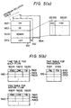
- Fig. 4 and Figs. 5(a) and 5(b) show the formats of the tables which are set in the file indicated at numeral 10001 in Fig. 2.
- Fig. 4 shows the table which stores information on the respective programs, and which shall hereinafter be called the "program constitution table.”
- This table is made up of the tables (401, 402, (2003)) of the respective programs.
- the individual tables are assigned serial numbers, which shall be called “program Nos.”
- the format of the table 401 will be elucidated.
- the tables 402, ...... have the same format.
- Symbol ICC 4011 denotes an area in which the content code of data to serve as the input of the corresponding program is stored
- symbol OCC 4012 denotes an area in which the content code of the output data of the program is stored
- TIME 4013 indicates an area for storing the processing time of the program
- PNO 4014 an area for storing the processor No. of the processor in which the program is stored
- PINF 4015 an area for storing the attribute of the program (for example, the program identifier).
- the program constitution table shall be previously set before the execution of the method of the present invention.
- this table can be set by keying-in the necessary information items from the CRT terminal (1001 in Fig. 2).
- Figs. 5(a) and 5(b) show the tables which are generated on the basis of the program constitution table shown in Fig. 4 by the method of the present invention.
- Fig. 5(a) shows the table indicative of the relations among the programs (hereinafter, called the "program relation table").
- the program relation table is made up of the tables 551 - 55m of the respective programs, and these tables are identified by respectively assigned serial Nos. (program relation table Nos.).
- the tables 552 - 55m have the same format.
- the table 551 is configured of a program pointer PP 5511, a table status ST 5512, a downstream information DOWNI 5513, and a level area LEV 5514.
- the program pointer PP 5511 is an area for storing a pointer which indicates the position of the program corresponding to this table, within the program constitution table (Fig. 4), and it has the program No. set therein.
- the table status ST 5512 is an area for setting therein information which indicates whether this table is in a normal status or in a relay status.
- the downstream information DOWNI 5513 there is stored the information of the program which lies downstream on the data flow of the program corresponding to this table.
- the area DOWNI is composed of content codes OCC 551310 which this program delivers as outputs, and pointers PRP 551311 which indicate the positions of the programs for receiving data items having the content codes as inputs, within the program constitution table.
- the pointers PRP 551311 are the program Nos. of the program constitution table shown in Fig. 4.
- Fig. 5(b) shows the tables which are generated on the basis of the program relation table shown in Fig. 5(a) during the execution of the simulation of the present invention, and which serve to store elaspsed times at the several stages of the simulation.
- the table 560 is a table (a time table for flows) which stores the elapsed times of a series of respective programs (hereinafter, called "system flows") that are successively started, and which is made up of rows 5601, 5602, « that correspond to the respective flows.
- the first row 5601 is composed of an area PMD 56011 for storing information which indicates an adjacent program lying upstream of a program being presently handled, an area CMD 56012 for storing information which indicates the program being presently handled, and an area TM 56013 for storing the elapsed time.
- the second row 5602, et seq. have the same composition as that of the first row 5601.
- the table 1560 is a table (a time table for previous-level flows) which serves to keep the contents of the table 560 and which has the same format as that of the table 560.
- the table 570 is a table (a time table for processors) which stores the elapsed times of the respective processors, and which is made up of rows 5701, 5702, ......
- the first row 5701 is composed of an area PN 57011 for storing processor No., and an area TM 57012 for storing the elapsed time.
- the second row 5702, et seq. have the same composition as that of the first row 5701.
- Fig. 1 shows the processing flow of the program 101 within the processor 11 shown in Fig. 2.
- the program 101 carries out the simulation in accordance with inputs from the CRT terminal 1001.
- information which triggers a system flow (programs) for starting the simulation (the identifier of a program to be first started, or the content code of data to be input to the program) is fetched from the CRT terminal 1001 (step 1011).
- the system flow which is started by the trigger obtained at the step 1011 is generated on the basis of the contents of the program constitution table shown in Fig. 4 (step 1012).
- step 1013 the processing time of the whole system flow is calculated (step 1013) on the basis of the system flow obtained at the step 1012, and the processing time information items (TIME 4013 in Fig. 4) and processor Nos. (PNO 4014 in Fig. 4) of the individual programs contained in the program constitution table.
- the calculated result is output to the CRT terminal 1001 (step 1014).
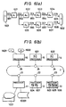
- Figs. 6(a) and 6(b) exemplify the application programs which are set in the system shown in Fig. 2.
- Fig. 6(a) schematically depicts the relation among the programs (the system flow).
- the processor 16 fetches data from the external input unit 1601, and supplies the transmission path with data 651 having a content code CC1. This data becomes the input data of a program A1 (601).
- the program A1 executes a process in accordance with the content of the input data 651, and outputs data 652 having a content code CC2 as the result.
- the data 652 becomes the input data of programs A2 (602) and A5 (605).
- the programs A2 and A5 execute processes according to the input data, and they output data items 653 and 656 having content codes CC3 and CC6, respectively.
- a program A3 (603) is started by the data 653 and outputs data 654 having a content code CC4, whereupon a program A4 (604) is started by data 654 and outputs data 655 having a content code CC5.
- programs A6 (606) and A7 (607) are successively started by the data 656, and the program A7 outputs data 658 having a content code CC8.
- the data items 655 and 658 are delivered to the external output unit 1602 by the processor 16.
- Fig. 6(b) is a diagram showing how the programs illustrated in Fig. 6(a) are arranged in the system.
- the program A1 is set in the processor 15; the program A2 in the processor 14; the programs A3, A5 and A6 in the processor 13; and the programs A4 and A7 in the processor 12.
- Fig. 7(a) shows a flow elucidating the contents of the process of the step 1012 in Fig. 1. It is now assumed that the program A1 in the processor 15 shown in Fig. 6(b) has been designated by the step 1011 in Fig. 1. Then, the position of the designated program within the program constitution table shown in Fig. 4, namely, the program No. thereof is found (step 701). It is set in the area PP of the first program relation table (551 in Fig.
- step 702 the program constitution table is searched for a program which is to be started by the data of the content code, and a program relation table corresponding thereto is set. Subsequently, a variable L indicative of a level (hereinafter, called "level variable”) is made '0', and '0' is set in the area LEV of the program relation table 551 (step 703).
- level variable a variable indicative of a level
- the expression "level” signifies a pointer whose value is set at '0' for the program to be first started within the system flow (the program A1 in this case) and is increased in a manner to be '1' for an adjacent downstream program and '2' for a still downstream program.
- the operating flow shifts to the processing step 704 of searching for a program or programs (A2 and A5 in this case) of the L-th level (the 0-th level in this case), to which the output data (652 in Fig. 6) of the program A1 (601 in Figs. 6(a) and 6(b)) is input.
- Fig. 7(b) shows the contents of the processing step 704. The process of Fig.
- the table status area ST 5512 of the 0-th level program relation table indicates the normal status (step 751), so that the program constitution table is searched for a program or programs the content code of the input data of which is the content code CC2 of the output data of the program A1 to-be-handled (step 752). Since, in this case, the programs A2 and A5 are the corresponding programs, program Nos. corresponding to the programs A2 and A5 are respectively set in the program pointer areas PP of the program relation tables 552 and 553 in Fig. 5(a).
- the normal status is set in the table status areas ST, and (L + 1) (namely, '1') is set in the level areas LEV.
- program relation table Nos. corresponding to the program relation tables 552 and 553 are set in the downstream information area DOWNI of the program relation table 551 (step 753).
- the operating flow shifts to a processing step 754. Since, in this case, the first level programs A2 and A5 and the 0-th level program A1 are separate programs, the process (the step 704 in Fig. 7(a)) is ended in the above state. Subsequently, the operating flow shifts to a processing step 705 in Fig.
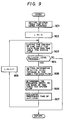
- Fig. 9 depicts a flow showing the contents of the processing step 1013 in Fig. 1.
- Fig. 10(a) shows a system flow to be handled here, and values indicated within ( ) for the respective programs are the processing times of the programs (that is, the contents of the areas TIME 4013 of the program constitution table in Fig. 4).
- the time table for flows 560 in Fig. 5(b)
- the time table for processors 570 in Fig.
- information indicative of the program A1 (concretely, the value of the area PP of the module relation table) is set in the area for the current level program, CMD at the first row of the time table for flows, and the processing time '2' of the program A1 is set in the area for the elapsed time, TM (refer to level 0 in Fig. 10(b)).
- '0' is set as the level variable L, whereupon the contents of the "time table for flows" are copied in the "time table for previous-level flows" shown in Fig. 5(b) (step 903).
- a program of the (L + 1)-th level exists is decided (step 904).
- the operating flow shifts to a processing step 905.
- the items of the time table for flows are set in correspondence with the programs of the (L + 1)-th level.
- the programs A2 and A5 exist at the first level, both the upstream programs thereof are the program A1, and the area ST of the module relation table corresponding to the program A1 indicates the normal mode, so that the program No. of the program constitution table corresponding to the programme A1 is set in the upstream program area PMD at the first row 5601 of the "time table for flows," and the program No. corresponding to the program A2 is set in the current level program area CMD.
- the program Nos is set in the current level program area
- processing times of the respective programs at the (L + 1)-th level are evaluated according to the evaluation order determined by the processing step 906 (step 907).
- the evaluation here is done in conformity with the following processing time calculative formulas:
- step 908 the level variable L is incremented by one (step 908), and the operating flow returns again to the processing step 903, at which the contents of the "time table for flows" are copied in the "time table for previous-level flows.”
- programs (A3, A6) at the (L + 1)-th level namely, the second level
- the operating flow shifts to the processing step 905, at which the areas PMD and CMD of the "time table for flows" are set similarly to the preceding time (level 2 in Fig. 10(b)).
- the operating flow shifts to the processing step 906, at which either of the programs A3 and A6 to be evaluated earlier is determined.
- the operations of the respective programs can be simulated merely by setting the input/output data items and processing times of the individual programs and information items on the processors in which the programs are stored.
- the performance evaluation with the transmission delay taken into consideration can be done in such a way that a data transfer time within the processor and a data transfer time between the processors are given as additional information and that the transfer times are added when the processing time of the system flow is calculated.
- the embodiment has referred to only the case of the single system flow, the performance evaluation can be done by applying the method even in such a case where a plurality of system flows run in parallel.
- processors for executing the method need not be connected to the transmission path.
- the operations of the respective programs can be simulated merely by defining the input/output data items and processing times of the individual programs and processors in which the programs are stored.
Description
- The present invention relates, in a distributed processing system for executing a series of processes with a plurality of programs, to a simulation method for evaluating the performances of the programs.
- In a distributed processing system wherein a series of processes are distributively carried out by a plurality of processors connected to a common transmission path; a method in which programs for executing the series of processes respectively are distributively stored in the corresponding processors and in which the program of each processor is started when data items required for executing this program have been completely gathered from the transmission path into its own processor, is disclosed in, for example, the official gazette of Japanese Patent Application Laid-open No. 146361/1982 (corresponding to JP-A-57 146 361. This method makes it possible that the series of respective processes are distributively executed by the corresponding processors without needing an executive processor for managing the whole system.
- As an expedient for simulating the system, there is a program package described in, for example, "HITAC Manual, GPSS, Introduction" which is disclosed in pages 248 to 270 of "Computer Simulation Techniques", by T.H. Naylor et al., John Wiley & Sons, Inc. 1966.
- In the article "Practical Multiprocessor Scheduling Algorithms for Efficient Parallel Processing", of H. Kasarara et al. in: "Systems and Computers in Japan", Vol. 16, No. 2, Washington, 1985,
pages 11 to 19 an optimization algorithm for scheduling a set of program modules forming a program by parallel processing is described. The simulation for producing an optimized system flow diagram is based on a previously defined taskgraph representing the relations among the various program modules in the system. - Regarding the distributed processing system referred to in the prior art, in case of designing the system, there has not been any method for previously evaluating how the individual programs operate, in other words, the performances, responses etc. of the programs. Therefore, how the system may be designed is difficult of evaluation, which has been problematic in the system design.
- With these techniques, however, the motion of the system must be first put into a model, according to which the sequence of the processes is described. This has led to the problem that the techniques cannot be easily applied.
- An object of the present invention is to provide, in the distributed processing system, a simulation method for programs which facilitates the development of a system and which enhances the reliability of software.
- This object is solved by a method according to
claim 1. - In order to accomplish the object, the present invention consists in giving each program the input/output data thereof, a processor for storing the program, and information on the processing time of the program beforehand, and comprising:
- (1) joining any desired program with a program to which the output data of the desired program is input, and
- (2) adding the processing times given to the respective programs, in a designated program sequence.
- In the present invention, by successively executing the aforementioned step (1), the starting flow of the series of programs (hereinafter, called "system flow") can be generated with respect to any desired program in such a manner that another program is started by the result of execution of the desired program and that a further program is started by the result of execution of the other program.
- Moreover, the aforementioned step (2) is applied to the system flow generated by the step (1), whereby the processing time of the whole system flow can be calculated.
- Fig. 1 is a diagram showing the general processing flow of a method according to the present invention;
- Fig. 2 is a system architecture diagram exemplifying a system to which the present invention is applied;
- Fig. 3 is a diagram showing an example of the format of a message which is transmitted;
- Fig. 4 and Figs. 5(a) and 5(b) are diagrams showing examples of the formats of tables which are used in the present invention;
- Figs. 6(a) and 6(b) are diagrams showing examples of application programs which are set in the system shown in Fig. 2;
- Figs. 7(a) and 7(b) and Fig. 9 are diagrams showing examples of parts of the processing flow of the method of the present invention; and
- Fig. 8 and Figs. 10(a) and 10(b) are diagrams showing examples of tables generated according to the present invention.
- Now, the present invention will be described in detail in conjunction with embodiments. Fig. 2 is a whole architecture diagram of a system to which the method of the present invention is applied. Although, in the ensuing embodiments, a common transmission path for connecting individual processors will be illustrated as a single-loop transmission system by way of example, any of general transmission media may well be employed.
- Referring to Fig. 2, numerals 11 - 16 indicate processors whose internal memories store application programs and which execute the programs, and
numeral 1 indicates a unidirectional loop transmission path which transmits data in the direction of arrows. Numerals 21 - 26 denote network control processors (hereinbelow, termed "NCPs") which control the data transmission on the transmission path. The respective NCPs 21 - 26 and the corresponding processors 11 - 16 are connected bidirectionally. Processed results (data) in the processors 11 - 16 are broadcast onto the transmission path via the NCPs 21 - 26. Each of NCPs 21 - 26 decides if data flowing on the transmission path is necessary for the processor connected to its own, and it sends the data to its own processor only when the data has been decided necessary. Each of the processors 11 - 16 starts the application program stored therein at the point of time at which all data items necessary for the execution of the program have been completely gathered. The started program executes its own process by the use of the data items, and outputs the result of the process. - In this embodiment, the
processor 11 is assumed to be a development system. Aprogram 101 for performing the simulation method of the present invention is set in theprocessor 11, and aCRT terminal 1001 for a man-machine interface and afile 10001 for storing tables required for the execution of the method are connected to this processor. In addition, theprocessor 16 is an I/O managing processor, to which anexternal input unit 1601 and anexternal output unit 1602 are connected. Thisprocessor 16 fetches data from an external process through theexternal input unit 1601 and delivers the data onto the transmission path, while it fetches data from the transmission path and delivers the data to an external process through theexternal output unit 1602. - Shown in Fig. 3 is the format of data which flows on the transmission path.
Symbol CC 302 denotes a content code, which is a code corresponding to the content of the data. On the basis of this content code, each NCP judges whether or not the received data is necessary for the processor connected to its own. Symbol SA 303 denotes an NCP address having sent the message, and symbol C 304 a consecutive number required for transmission.DATA 305 indicates the data of the processed result of each application program, and FCS 306 indicates error sensing data. F 301 and F 307 denote flags which indicate the start and end of the message, respectively. - The present invention is directed toward the distributed processing system as explained above, and is intended to simulate the operations of the application programs in the case where these programs are set in the respective processors. Now, the simulation method of the present invention will be described with reference to Fig. 4 - Figs. 10(a) and 10(b).
- Fig. 4 and Figs. 5(a) and 5(b) show the formats of the tables which are set in the file indicated at
numeral 10001 in Fig. 2. Fig. 4 shows the table which stores information on the respective programs, and which shall hereinafter be called the "program constitution table." This table is made up of the tables (401, 402, ......) of the respective programs. In addition, the individual tables are assigned serial numbers, which shall be called "program Nos." Next, the format of the table 401 will be elucidated. The tables 402, ...... have the same format.Symbol ICC 4011 denotes an area in which the content code of data to serve as the input of the corresponding program is stored, while symbol OCC 4012 denotes an area in which the content code of the output data of the program is stored. Besides,TIME 4013 indicates an area for storing the processing time of the program, PNO 4014 an area for storing the processor No. of the processor in which the program is stored, and PINF 4015 an area for storing the attribute of the program (for example, the program identifier). Incidentally, the program constitution table shall be previously set before the execution of the method of the present invention. By way of example, this table can be set by keying-in the necessary information items from the CRT terminal (1001 in Fig. 2). - Figs. 5(a) and 5(b) show the tables which are generated on the basis of the program constitution table shown in Fig. 4 by the method of the present invention. Fig. 5(a) shows the table indicative of the relations among the programs (hereinafter, called the "program relation table"). The program relation table is made up of the tables 551 - 55m of the respective programs, and these tables are identified by respectively assigned serial Nos. (program relation table Nos.). Next, the format of the table 551 will be elucidated. The tables 552 - 55m have the same format. The table 551 is configured of a
program pointer PP 5511, atable status ST 5512, adownstream information DOWNI 5513, and alevel area LEV 5514. Theprogram pointer PP 5511 is an area for storing a pointer which indicates the position of the program corresponding to this table, within the program constitution table (Fig. 4), and it has the program No. set therein. Thetable status ST 5512 is an area for setting therein information which indicates whether this table is in a normal status or in a relay status. In thedownstream information DOWNI 5513, there is stored the information of the program which lies downstream on the data flow of the program corresponding to this table. The area DOWNI is composed ofcontent codes OCC 551310 which this program delivers as outputs, andpointers PRP 551311 which indicate the positions of the programs for receiving data items having the content codes as inputs, within the program constitution table. Concretely, thepointers PRP 551311 are the program Nos. of the program constitution table shown in Fig. 4. - Fig. 5(b) shows the tables which are generated on the basis of the program relation table shown in Fig. 5(a) during the execution of the simulation of the present invention, and which serve to store elaspsed times at the several stages of the simulation. The table 560 is a table (a time table for flows) which stores the elapsed times of a series of respective programs (hereinafter, called "system flows") that are successively started, and which is made up of
rows first row 5601 is composed of anarea PMD 56011 for storing information which indicates an adjacent program lying upstream of a program being presently handled, anarea CMD 56012 for storing information which indicates the program being presently handled, and anarea TM 56013 for storing the elapsed time. Thesecond row 5602, et seq. have the same composition as that of thefirst row 5601. In addition, the table 1560 is a table (a time table for previous-level flows) which serves to keep the contents of the table 560 and which has the same format as that of the table 560. The table 570 is a table (a time table for processors) which stores the elapsed times of the respective processors, and which is made up ofrows first row 5701 is composed of anarea PN 57011 for storing processor No., and anarea TM 57012 for storing the elapsed time. Thesecond row 5702, et seq. have the same composition as that of thefirst row 5701. - Fig. 1 shows the processing flow of the
program 101 within theprocessor 11 shown in Fig. 2. Theprogram 101 carries out the simulation in accordance with inputs from theCRT terminal 1001. First, information which triggers a system flow (programs) for starting the simulation (the identifier of a program to be first started, or the content code of data to be input to the program) is fetched from the CRT terminal 1001 (step 1011). Subsequently, the system flow which is started by the trigger obtained at thestep 1011 is generated on the basis of the contents of the program constitution table shown in Fig. 4 (step 1012). Thereafter, the processing time of the whole system flow is calculated (step 1013) on the basis of the system flow obtained at thestep 1012, and the processing time information items (TIME 4013 in Fig. 4) and processor Nos. (PNO 4014 in Fig. 4) of the individual programs contained in the program constitution table. The calculated result is output to the CRT terminal 1001 (step 1014). Now, the processes of thesteps - Figs. 6(a) and 6(b) exemplify the application programs which are set in the system shown in Fig. 2. Fig. 6(a) schematically depicts the relation among the programs (the system flow). The
processor 16 fetches data from theexternal input unit 1601, and supplies the transmission path withdata 651 having a content code CC1. This data becomes the input data of a program A₁ (601). The program A₁ executes a process in accordance with the content of theinput data 651, andoutputs data 652 having a content code CC2 as the result. Thedata 652 becomes the input data of programs A₂ (602) and A₅ (605). The programs A₂ and A₅ execute processes according to the input data, and theyoutput data items data 653 andoutputs data 654 having a content code CC4, whereupon a program A₄ (604) is started bydata 654 andoutputs data 655 having a content code CC5. Similarly, programs A₆ (606) and A₇ (607) are successively started by thedata 656, and the programA₇ outputs data 658 having a content code CC8. Thedata items external output unit 1602 by theprocessor 16. Fig. 6(b) is a diagram showing how the programs illustrated in Fig. 6(a) are arranged in the system. The program A₁ is set in theprocessor 15; the program A₂ in theprocessor 14; the programs A₃, A₅ and A₆ in theprocessor 13; and the programs A₄ and A₇ in theprocessor 12. - Hereunder, the program constitution shown in Figs. 6(a) and 6(b) will be taken as a concrete example. First, the process of the
step 1012 in Fig. 1 will be described with reference to Figs. 7(a) - 8. Fig. 7(a) shows a flow elucidating the contents of the process of thestep 1012 in Fig. 1. It is now assumed that the program A₁ in theprocessor 15 shown in Fig. 6(b) has been designated by thestep 1011 in Fig. 1. Then, the position of the designated program within the program constitution table shown in Fig. 4, namely, the program No. thereof is found (step 701). It is set in the area PP of the first program relation table (551 in Fig. 5(a)), and the normal status is set in the area ST (step 702). By the way, in a case where a content code has been designated by thestep 1011 in Fig. 1, the program constitution table is searched for a program which is to be started by the data of the content code, and a program relation table corresponding thereto is set. Subsequently, a variable L indicative of a level (hereinafter, called "level variable") is made '0', and '0' is set in the area LEV of the program relation table 551 (step 703). Here, the expression "level" signifies a pointer whose value is set at '0' for the program to be first started within the system flow (the program A₁ in this case) and is increased in a manner to be '1' for an adjacent downstream program and '2' for a still downstream program. Next, the operating flow shifts to theprocessing step 704 of searching for a program or programs (A₂ and A₅ in this case) of the L-th level (the 0-th level in this case), to which the output data (652 in Fig. 6) of the program A₁ (601 in Figs. 6(a) and 6(b)) is input. Fig. 7(b) shows the contents of theprocessing step 704. The process of Fig. 7(b) is carried out for all the program relation tables which belong to the L-th level. First, the tablestatus area ST 5512 of the 0-th level program relation table indicates the normal status (step 751), so that the program constitution table is searched for a program or programs the content code of the input data of which is the content code CC2 of the output data of the program A₁ to-be-handled (step 752). Since, in this case, the programs A₂ and A₅ are the corresponding programs, program Nos. corresponding to the programs A₂ and A₅ are respectively set in the program pointer areas PP of the program relation tables 552 and 553 in Fig. 5(a). Besides, the normal status is set in the table status areas ST, and (L + 1) (namely, '1') is set in the level areas LEV. Simultaneously therewith, program relation table Nos. corresponding to the program relation tables 552 and 553 are set in the downstream information area DOWNI of the program relation table 551 (step 753). Next, the operating flow shifts to a processing step 754. Since, in this case, the first level programs A₂ and A₅ and the 0-th level program A₁ are separate programs, the process (thestep 704 in Fig. 7(a)) is ended in the above state. Subsequently, the operating flow shifts to aprocessing step 705 in Fig. 7(a), which decides whether or not a program relation table corresponding to the (L + 1)-th level exists. Since, in this case, the programs A₂ and A₅ exist as the programs corresponding to the (L + 1)-th level, namely, the first level, the operating flow shifts to aprocessing step 706, at which the level variable L is renewed to '1' and which is followed by theprocessing step 704. Thenceforth, the control operation is similarly performed until module relation tables are set as illustrated in Fig. 8. After the module relation tables have been set up to the third level, the fourth level program does not exist at theprocessing step 705, and hence, theprocessing step 1012 shown in Fig. 1 is ended. - Next, the process of the
step 1013 in Fig. 1 will be described with reference to Figs. 9 - 10(b). Fig. 9 depicts a flow showing the contents of theprocessing step 1013 in Fig. 1. In addition, Fig. 10(a) shows a system flow to be handled here, and values indicated within ( ) for the respective programs are the processing times of the programs (that is, the contents of theareas TIME 4013 of the program constitution table in Fig. 4). In the process of thestep 1013 in Fig. 1, the time table for flows (560 in Fig. 5(b)) and the time table for processors (570 in Fig. 5(b)) are first set in correspondence with the 0-th level program (A₁ in this case) as indicated at astep 901 in Fig. 9. Since the program A₁ is set in theprocessor 15, '2' being the processing time of the program A₁ is set in the area TM of that row of the time table for processors which corresponds to theprocessor 15. Besides, '0' is set in the areas TM of the rows corresponding to the other processors. Subsequently, information indicative of the program A₁ (concretely, the value of the area PP of the module relation table) is set in the area for the current level program, CMD at the first row of the time table for flows, and the processing time '2' of the program A₁ is set in the area for the elapsed time, TM (refer tolevel 0 in Fig. 10(b)). Next, '0' is set as the level variable L, whereupon the contents of the "time table for flows" are copied in the "time table for previous-level flows" shown in Fig. 5(b) (step 903). Thereafter, whether or not a program of the (L + 1)-th level exists is decided (step 904). Since, in this case, the programs A₂ and A₅ exist as the first level programs, the operating flow shifts to aprocessing step 905. At theprocessing step 905, the items of the time table for flows are set in correspondence with the programs of the (L + 1)-th level. The programs A₂ and A₅ exist at the first level, both the upstream programs thereof are the program A₁, and the area ST of the module relation table corresponding to the program A₁ indicates the normal mode, so that the program No. of the program constitution table corresponding to the programme A₁ is set in the upstream program area PMD at thefirst row 5601 of the "time table for flows," and the program No. corresponding to the program A₂ is set in the current level program area CMD. Likewise, the program Nos. corresponding to the programs A₁ and A₅ are respectively set in the areas PMD and CMD at thesecond row 5602 of the "time table for flows" (level 1 in Fig. 10(b)). Subsequently, the (L + 1)-th level program from which the processing time is evaluated is determined on the basis of the contents of the "time table for previous-level flows" (step 906). The determination here is done in conformity with the following evaluation order determinant criteria: -
- (1) The evaluation is started from a program lying downstream of a program at that row of the "time table for previous-level flows" which has a smaller value in the elapsed time area TM.
- (2) In a case where, in the criterion (1), a plurality of programs lie downstream of the program at the row having the smaller TM value, the evaluation order of the plurality of programs is determined on the basis of a criterion given beforehand (for example, the order in which they have been registered).
- In the case of Fig. 10(a) to be handled here, only the program A₁ exists upstream of the first level programs A₂ and A₅, and this case falls under the criterion (2). On this occasion, the evaluation shall be started from the program A₂ on the basis of the criterion given beforehand.
- Subsequently, the processing times of the respective programs at the (L + 1)-th level are evaluated according to the evaluation order determined by the processing step 906 (step 907). The evaluation here is done in conformity with the following processing time calculative formulas:
- (1) Case where a subject program and the upstream program thereof are set in different processors;
·max {(TM value of the row of the "time table for previous -level flows" corresponding to the flow to which the subject program belongs), (TM value of the row of the "time table for processors" corresponding to the processor in which the subject program is set)} + (processing time of the subject program)
Here, when the subject program is started by a plurality of input data items, the maximum one of the TM values of the "time table for previous-level flows" corresponding to the flows to which the programs outputting the input data items belong is taken as the first term of max { }.
(2) Case where a subject program and the upstream program thereof are set in an identical processor;
·(TM value of the row of the "time table for processors" corresponding to the processor in which the subject program is set) + (processing time of the subject program)
On the basis of the above calculative formulas, the program A₂ is evaluated as follows: Since the program A₂ (processor 14) and the upstream program A₁ thereof (processor 15) are set in the separate processors,
is calculated according to the calculative formula (1). This value is set in the area TM of the row of the "time table for processors" corresponding to theprocessor 14 to which the program A₂ belongs. Besides, this value is set in the area TM of the row of the "time table for flows" corresponding to the flow to which the program A₂ belongs. - Subsequently, the program A₅ is evaluated. Since also the program A₅ (processor 13) is set in the processor separate from that of the program A₂,

is calculated according to the calculative formula (1). This value is set in the area TM of the row of the "time table for processors" corresponding to theprocessor 13. Besides, this value is set in the area TM of the row of the "time table for flows" corresponding to the flow to which the program A₅ belongs (level 1 in Fig. 10(b)). Thus, theprocessing step 907 for L = 0 is ended. Subsequently, the level variable L is incremented by one (step 908), and the operating flow returns again to theprocessing step 903, at which the contents of the "time table for flows" are copied in the "time table for previous-level flows." Next, since programs (A₃, A₆) at the (L + 1)-th level (namely, the second level) exist (step 904), the operating flow shifts to theprocessing step 905, at which the areas PMD and CMD of the "time table for flows" are set similarly to the preceding time (level 2 in Fig. 10(b)). Subsequently, the operating flow shifts to theprocessing step 906, at which either of the programs A₃ and A₆ to be evaluated earlier is determined. In this case, the programs A₆ and A₃ are evaluated in this order at theprocessing step 907 in accordance with <Evaluation order determining criterion> (1).
Since both the programs A₆ and the upstream program A₅ thereof lie in theprocessor 
is calculated in accordance with <Processing time-calculating formula> (2). This value is set in the area TM of the row of the "time table for processors" corresponding to theprocessor 13. Besides, this value is set in the area TM of the row of the "time table for flows" corresponding to the flow to which the program A₆ belongs. Subsequently, since the program A₃ (processor 13) and the upstream program A₂ thereof (processor 12) lie in the separate processors,
is calculated in accordance with <Processing time-calculating formula> (1). This value is set in the area TM of the row of the time "time table for processors" corresponding to theprocessor 13. Besides, this value is set in the area TM of the row of the "time table for flows" corresponding to the flow to which the program A₃ belongs (management tables oflevel 2 in Fig. 10(b)). Thus, the process for L = 1 is ended. Thenceforth, the process is similarly carried out according to the flow of Fig. 9 until the "time table for flows" oflevel 3 in Fig. 10(b) is eventually obtained. Owing to this table, it is found that, in the case of the system flow shown in Fig. 10(a), the processing time taken since the start of the program A₁ till the end of the program A₄ is 13, while the processing time taken till the end of the program A₇ is 10. - Owing to the method stated above, the operations of the respective programs can be simulated merely by setting the input/output data items and processing times of the individual programs and information items on the processors in which the programs are stored.
- By the way, although in the embodiment a transmission delay which arises at the data transfer between the programs is assumed to be null, the performance evaluation with the transmission delay taken into consideration can be done in such a way that a data transfer time within the processor and a data transfer time between the processors are given as additional information and that the transfer times are added when the processing time of the system flow is calculated.
- Besides, although the embodiment has referred to only the case of the single system flow, the performance evaluation can be done by applying the method even in such a case where a plurality of system flows run in parallel.
- Besides, although the embodiment has referred to the case of the system wherein the programs are distributively arranged in the plurality of processors, naturally the method is also applicable to a system constructed of only a single processor.
- Besides, although the embodiment has referred to the example in which the method is executed by the processors connected to the transmission path, processors for executing the method need not be connected to the transmission path.
- According to the present invention, in a system wherein a series of processes are executed by a plurality of programs, the operations of the respective programs can be simulated merely by defining the input/output data items and processing times of the individual programs and processors in which the programs are stored. Thus, it becomes possible to easily evaluate the performance, responsiveness etc. of a designed system in case of a system design, so that the efficiency of development of software rises. Moreover, problems concerning the performance (a bottleneck, etc.) can be easily detected at the stage of the design by the method of the invention, so that the reliability of the software is enhanced.
Claims (6)
- A method for simulating processing of a plurality of program modules (A1...A7) in a distributed processing system, wherein a series of processes is executed by programs which are distributively arranged in a plurality of processors (12...16) which are interconnected by a transmission means (1), said method being executed in a program simulation processor (11) having an input/output device (1001) and a memory (10001), characterised by the steps of :
storing in said memory (10001) a program constitution table containing information relating to input/output data and processing time of each one of said plurality of program modules and to the processor in which said each program module is processed;
fetching (1011) information to be input to said series of processes from said input/output device (1001) indicating a given one of said plurality of program modules to be first simulated;
producing (1012) a system flow diagram defining an interrelational order of said plurality of program modules based on said fetched information and said information relating to the input/output data of said program constitution table by interrelating each program module with program modules whose input data is the output data of said each program module;
evaluating (1013) performance of the system based on said information relating to the processing time of said respective program modules having said interrelational order defined by said system flow diagram by adding at least the processing times given to the respective program modules according to said interrelational order; and
outputting (1014) to said input/output device (1001) the result of said evaluating step. - The method according to claim 1, wherein said producing step (1012) includes a step of generating a program relation table for each one of said plurality of program modules, said program relation table having information relating to a program module whose input data is the output data of the program module associated with said program relation table.
- The method according to claim 1 or 2, wherein said evaluating step (1013) includes a step of generating a time table for storing elapsed times of the respective program modules according to said interrelational order.
- The method according to any one of claims 1 to 3, wherein said evaluating step (1013) includes a step of generating a time table for storing elapsed times of the respective processors associated with the program modules according to said interrelational order.
- The method according to any one of claims 1 to 4, wherein said evaluating step (1013) includes a step of adding data transmission times between the respective processors to the processing times of the respective program modules according to said interrelational order.
- The method according to any one of claims 1 to 5, wherein the simulation processing is carried out for a plurality of system flow diagrams in parallel.
Applications Claiming Priority (2)
| Application Number | Priority Date | Filing Date | Title |
|---|---|---|---|
| JP99754/87 | 1987-04-24 | ||
| JP9975487A JP2550063B2 (en) | 1987-04-24 | 1987-04-24 | Distributed processing system simulation method |
Publications (3)
| Publication Number | Publication Date |
|---|---|
| EP0288043A2 EP0288043A2 (en) | 1988-10-26 |
| EP0288043A3 EP0288043A3 (en) | 1990-03-28 |
| EP0288043B1 true EP0288043B1 (en) | 1994-11-17 |
Family
ID=14255772
Family Applications (1)
| Application Number | Title | Priority Date | Filing Date |
|---|---|---|---|
| EP88106337A Expired - Lifetime EP0288043B1 (en) | 1987-04-24 | 1988-04-20 | Simulation method for programs |
Country Status (4)
| Country | Link |
|---|---|
| US (1) | US5097412A (en) |
| EP (1) | EP0288043B1 (en) |
| JP (1) | JP2550063B2 (en) |
| DE (1) | DE3852115T2 (en) |
Families Citing this family (27)
| Publication number | Priority date | Publication date | Assignee | Title |
|---|---|---|---|---|
| EP0372682A3 (en) * | 1988-12-05 | 1991-07-17 | Digital Equipment Corporation | System characterization method |
| DE69033434T2 (en) * | 1989-07-31 | 2000-08-03 | Hitachi Ltd | Data processing system and data transmission and processing method |
| US5442772A (en) * | 1991-03-29 | 1995-08-15 | International Business Machines Corporation | Common breakpoint in virtual time logic simulation for parallel processors |
| US5617538A (en) * | 1991-07-02 | 1997-04-01 | Tm Patents, L.P. | Message transfer system and method for parallel computer with message transfers being scheduled by skew and roll functions to avoid bottlenecks |
| JPH05216712A (en) * | 1991-10-23 | 1993-08-27 | Internatl Business Mach Corp <Ibm> | Computer system, method for performing inner-viewing task on computer system and i/o processor assembly |
| US5724556A (en) * | 1995-04-14 | 1998-03-03 | Oracle Corporation | Method and apparatus for defining and configuring modules of data objects and programs in a distributed computer system |
| US5727167A (en) * | 1995-04-14 | 1998-03-10 | International Business Machines Corporation | Thresholding support in performance monitoring |
| US7257523B1 (en) | 1999-05-06 | 2007-08-14 | Fisher-Rosemount Systems, Inc. | Integrated distributed process control system functionality on a single computer |
| US7117136B1 (en) | 2000-08-18 | 2006-10-03 | Linden Research, Inc. | Input and feedback system |
| US8612196B2 (en) * | 2002-04-11 | 2013-12-17 | Linden Research, Inc. | System and method for distributed simulation in which different simulation servers simulate different regions of a simulation space |
| DE10348563B4 (en) * | 2002-10-22 | 2014-01-09 | Fisher-Rosemount Systems, Inc. | Integration of graphic display elements, process modules and control modules in process plants |
| US9983559B2 (en) * | 2002-10-22 | 2018-05-29 | Fisher-Rosemount Systems, Inc. | Updating and utilizing dynamic process simulation in an operating process environment |
| US7146231B2 (en) | 2002-10-22 | 2006-12-05 | Fisher-Rosemount Systems, Inc.. | Smart process modules and objects in process plants |
| US7308558B2 (en) * | 2004-01-07 | 2007-12-11 | International Business Machines Corporation | Multiprocessor data processing system having scalable data interconnect and data routing mechanism |
| US7007128B2 (en) * | 2004-01-07 | 2006-02-28 | International Business Machines Corporation | Multiprocessor data processing system having a data routing mechanism regulated through control communication |
| US7729789B2 (en) | 2004-05-04 | 2010-06-01 | Fisher-Rosemount Systems, Inc. | Process plant monitoring based on multivariate statistical analysis and on-line process simulation |
| JP2007536634A (en) * | 2004-05-04 | 2007-12-13 | フィッシャー−ローズマウント・システムズ・インコーポレーテッド | Service-oriented architecture for process control systems |
| GB2425622A (en) * | 2005-04-27 | 2006-11-01 | Ncapsa Ltd | Programming real-time systems using data flow diagrams |
| EP1969429A2 (en) | 2005-12-05 | 2008-09-17 | Fisher-Rosemount Systems, Inc. | Multi-objective predictive process optimization with concurrent process simulation |
| US7849362B2 (en) | 2005-12-09 | 2010-12-07 | International Business Machines Corporation | Method and system of coherent design verification of inter-cluster interactions |
| US7711534B2 (en) * | 2005-12-09 | 2010-05-04 | International Business Machines Corporation | Method and system of design verification |
| US9367493B2 (en) * | 2005-12-09 | 2016-06-14 | Globalfoundries Inc. | Method and system of communicating between peer processors in SoC environment |
| US8881039B2 (en) | 2009-03-13 | 2014-11-04 | Fisher-Rosemount Systems, Inc. | Scaling composite shapes for a graphical human-machine interface |
| US8825183B2 (en) * | 2010-03-22 | 2014-09-02 | Fisher-Rosemount Systems, Inc. | Methods for a data driven interface based on relationships between process control tags |
| US10878140B2 (en) | 2016-07-27 | 2020-12-29 | Emerson Process Management Power & Water Solutions, Inc. | Plant builder system with integrated simulation and control system configuration |
| US11604459B2 (en) | 2019-07-12 | 2023-03-14 | Emerson Process Management Power & Water Solutions, Inc. | Real-time control using directed predictive simulation within a control system of a process plant |
| US11418969B2 (en) | 2021-01-15 | 2022-08-16 | Fisher-Rosemount Systems, Inc. | Suggestive device connectivity planning |
Family Cites Families (26)
| Publication number | Priority date | Publication date | Assignee | Title |
|---|---|---|---|---|
| US3648253A (en) * | 1969-12-10 | 1972-03-07 | Ibm | Program scheduler for processing systems |
| US3678467A (en) * | 1970-10-20 | 1972-07-18 | Bell Telephone Labor Inc | Multiprocessor with cooperative program execution |
| US4315315A (en) * | 1971-03-09 | 1982-02-09 | The Johns Hopkins University | Graphical automatic programming |
| US3766524A (en) * | 1971-06-30 | 1973-10-16 | Ibm | Dynamic time slicing control for microprogrammed controller |
| US3763474A (en) * | 1971-12-09 | 1973-10-02 | Bell Telephone Labor Inc | Program activated computer diagnostic system |
| US4183083A (en) * | 1972-04-14 | 1980-01-08 | Duquesne Systems, Inc. | Method of operating a multiprogrammed computing system |
| US4149243A (en) * | 1977-10-20 | 1979-04-10 | International Business Machines Corporation | Distributed control architecture with post and wait logic |
| US4262331A (en) * | 1978-10-30 | 1981-04-14 | Ibm Corporation | Self-adaptive computer load control |
| US4393446A (en) * | 1979-08-20 | 1983-07-12 | General Electric Company | Routine timer for computer systems |
| FR2469751A1 (en) * | 1979-11-07 | 1981-05-22 | Philips Data Syst | SYSTEM INTERCOMMUNICATION PROCESSOR FOR USE IN A DISTRIBUTED DATA PROCESSING SYSTEM |
| DE2946081C3 (en) * | 1979-11-15 | 1995-09-21 | Wabco Vermoegensverwaltung | Circuit arrangement for monitoring the function of a microprocessor |
| JPS57757A (en) * | 1980-06-04 | 1982-01-05 | Hitachi Ltd | Job execution schedule system |
| US4403286A (en) * | 1981-03-06 | 1983-09-06 | International Business Machines Corporation | Balancing data-processing work loads |
| JPS57164636A (en) * | 1981-04-03 | 1982-10-09 | Hitachi Ltd | Control method for transmission system |
| US4740895A (en) * | 1981-08-24 | 1988-04-26 | Genrad, Inc. | Method of and apparatus for external control of computer program flow |
| US4517641A (en) * | 1982-04-30 | 1985-05-14 | International Business Machines Corporation | Lookahead I/O device control subsystem |
| US4583222A (en) * | 1983-11-07 | 1986-04-15 | Digital Equipment Corporation | Method and apparatus for self-testing of floating point accelerator processors |
| US4698751A (en) * | 1984-07-13 | 1987-10-06 | Ford Aerospace & Communications Corporation | Systolic array for solving cyclic loop dependent algorithms |
| US4837676A (en) * | 1984-11-05 | 1989-06-06 | Hughes Aircraft Company | MIMD instruction flow computer architecture |
| US4769772A (en) * | 1985-02-28 | 1988-09-06 | Honeywell Bull, Inc. | Automated query optimization method using both global and parallel local optimizations for materialization access planning for distributed databases |
| US4677587A (en) * | 1985-05-14 | 1987-06-30 | Sanders Associates, Inc. | Program simulation system including means for ensuring interactive enforcement of constraints |
| US4972314A (en) * | 1985-05-20 | 1990-11-20 | Hughes Aircraft Company | Data flow signal processor method and apparatus |
| US4703481A (en) * | 1985-08-16 | 1987-10-27 | Hewlett-Packard Company | Method and apparatus for fault recovery within a computing system |
| US4845665A (en) * | 1985-08-26 | 1989-07-04 | International Business Machines Corp. | Simulation of computer program external interfaces |
| US4814978A (en) * | 1986-07-15 | 1989-03-21 | Dataflow Computer Corporation | Dataflow processing element, multiprocessor, and processes |
| US4866663A (en) * | 1987-02-13 | 1989-09-12 | Sanders Associates, Inc. | Simulation system |
-
1987
- 1987-04-24 JP JP9975487A patent/JP2550063B2/en not_active Expired - Fee Related
-
1988
- 1988-04-20 EP EP88106337A patent/EP0288043B1/en not_active Expired - Lifetime
- 1988-04-20 DE DE3852115T patent/DE3852115T2/en not_active Expired - Fee Related
- 1988-04-21 US US07/184,395 patent/US5097412A/en not_active Expired - Lifetime
Also Published As
| Publication number | Publication date |
|---|---|
| DE3852115D1 (en) | 1994-12-22 |
| EP0288043A3 (en) | 1990-03-28 |
| US5097412A (en) | 1992-03-17 |
| JPS63266550A (en) | 1988-11-02 |
| DE3852115T2 (en) | 1995-03-23 |
| JP2550063B2 (en) | 1996-10-30 |
| EP0288043A2 (en) | 1988-10-26 |
Similar Documents
| Publication | Publication Date | Title |
|---|---|---|
| EP0288043B1 (en) | Simulation method for programs | |
| Holzmann | The model checker SPIN | |
| US4860201A (en) | Binary tree parallel processor | |
| US4797885A (en) | Distributed processing system and method | |
| US5561802A (en) | Method for managing programs with attribute information and developing loaded programs | |
| IL97177A (en) | Method for creating a sequential circuit | |
| CN113220542B (en) | Early warning method and device for computing task, computer equipment and storage medium | |
| JP2709705B2 (en) | Program management method in multi-computer system | |
| US7287246B2 (en) | Debugging optimized flows with breakpoints using stored breakpoint trigger indicators | |
| CN115794213A (en) | Configurable object management method, device and equipment based on embedded system | |
| Daws et al. | Automatic verification of the IEEE 1394 root contention protocol with KRONOS and PRISM | |
| US7512613B2 (en) | Non-intrusive data logging | |
| EP0263423B1 (en) | Distributed processing system and method | |
| Verbeek et al. | Verification of building blocks for asynchronous circuits | |
| US5335324A (en) | Distributed processing system and method for job execution using a plurality of processors and including identification of replicated data | |
| Мок | Fundamental Design Problems of Distributed Systems for the Hard Real-Time Environment | |
| Bertolotti et al. | Model-based design languages: a case study | |
| JP2590159B2 (en) | Environment setting method for integration test | |
| JPH0683900A (en) | Simulation method for system and simulation system | |
| Stoelinga | Gambling for leadership: Verification of root contention in IEEE 1394 | |
| Palumbo | Advanced techniques in reliability model representation and solution | |
| CN115470031A (en) | Abnormal event correction method, device, equipment and medium | |
| Treadwell | Estimating task execution delay in a real-time system via static source code analysis | |
| JP3385790B2 (en) | Language converter | |
| JP2656471B2 (en) | Distributed processing system and information processing method thereof |
Legal Events
| Date | Code | Title | Description |
|---|---|---|---|
| PUAI | Public reference made under article 153(3) epc to a published international application that has entered the european phase |
Free format text: ORIGINAL CODE: 0009012 |
|
| AK | Designated contracting states |
Kind code of ref document: A2 Designated state(s): DE FR GB |
|
| PUAL | Search report despatched |
Free format text: ORIGINAL CODE: 0009013 |
|
| AK | Designated contracting states |
Kind code of ref document: A3 Designated state(s): DE FR GB |
|
| RHK1 | Main classification (correction) |
Ipc: G06F 9/46 |
|
| 17P | Request for examination filed |
Effective date: 19900829 |
|
| 17Q | First examination report despatched |
Effective date: 19921020 |
|
| GRAA | (expected) grant |
Free format text: ORIGINAL CODE: 0009210 |
|
| AK | Designated contracting states |
Kind code of ref document: B1 Designated state(s): DE FR GB |
|
| REF | Corresponds to: |
Ref document number: 3852115 Country of ref document: DE Date of ref document: 19941222 |
|
| ET | Fr: translation filed | ||
| PLBE | No opposition filed within time limit |
Free format text: ORIGINAL CODE: 0009261 |
|
| STAA | Information on the status of an ep patent application or granted ep patent |
Free format text: STATUS: NO OPPOSITION FILED WITHIN TIME LIMIT |
|
| 26N | No opposition filed | ||
| REG | Reference to a national code |
Ref country code: GB Ref legal event code: IF02 |
|
| PGFP | Annual fee paid to national office [announced via postgrant information from national office to epo] |
Ref country code: FR Payment date: 20040322 Year of fee payment: 17 |
|
| PGFP | Annual fee paid to national office [announced via postgrant information from national office to epo] |
Ref country code: GB Payment date: 20040324 Year of fee payment: 17 |
|
| PGFP | Annual fee paid to national office [announced via postgrant information from national office to epo] |
Ref country code: DE Payment date: 20040608 Year of fee payment: 17 |
|
| PG25 | Lapsed in a contracting state [announced via postgrant information from national office to epo] |
Ref country code: GB Free format text: LAPSE BECAUSE OF NON-PAYMENT OF DUE FEES Effective date: 20050420 |
|
| PG25 | Lapsed in a contracting state [announced via postgrant information from national office to epo] |
Ref country code: DE Free format text: LAPSE BECAUSE OF NON-PAYMENT OF DUE FEES Effective date: 20051101 |
|
| GBPC | Gb: european patent ceased through non-payment of renewal fee |
Effective date: 20050420 |
|
| PG25 | Lapsed in a contracting state [announced via postgrant information from national office to epo] |
Ref country code: FR Free format text: LAPSE BECAUSE OF NON-PAYMENT OF DUE FEES Effective date: 20051230 |
|
| REG | Reference to a national code |
Ref country code: FR Ref legal event code: ST Effective date: 20051230 |