EP0286594A2 - Process for the production of photographically structurable coatings - Google Patents
Process for the production of photographically structurable coatings Download PDFInfo
- Publication number
- EP0286594A2 EP0286594A2 EP19880810207 EP88810207A EP0286594A2 EP 0286594 A2 EP0286594 A2 EP 0286594A2 EP 19880810207 EP19880810207 EP 19880810207 EP 88810207 A EP88810207 A EP 88810207A EP 0286594 A2 EP0286594 A2 EP 0286594A2
- Authority
- EP
- European Patent Office
- Prior art keywords
- radiation
- optionally
- coated
- oder
- film
- Prior art date
- Legal status (The legal status is an assumption and is not a legal conclusion. Google has not performed a legal analysis and makes no representation as to the accuracy of the status listed.)
- Withdrawn
Links
Classifications
-
- G—PHYSICS
- G03—PHOTOGRAPHY; CINEMATOGRAPHY; ANALOGOUS TECHNIQUES USING WAVES OTHER THAN OPTICAL WAVES; ELECTROGRAPHY; HOLOGRAPHY
- G03F—PHOTOMECHANICAL PRODUCTION OF TEXTURED OR PATTERNED SURFACES, e.g. FOR PRINTING, FOR PROCESSING OF SEMICONDUCTOR DEVICES; MATERIALS THEREFOR; ORIGINALS THEREFOR; APPARATUS SPECIALLY ADAPTED THEREFOR
- G03F7/00—Photomechanical, e.g. photolithographic, production of textured or patterned surfaces, e.g. printing surfaces; Materials therefor, e.g. comprising photoresists; Apparatus specially adapted therefor
- G03F7/16—Coating processes; Apparatus therefor
- G03F7/164—Coating processes; Apparatus therefor using electric, electrostatic or magnetic means; powder coating
-
- H—ELECTRICITY
- H05—ELECTRIC TECHNIQUES NOT OTHERWISE PROVIDED FOR
- H05K—PRINTED CIRCUITS; CASINGS OR CONSTRUCTIONAL DETAILS OF ELECTRIC APPARATUS; MANUFACTURE OF ASSEMBLAGES OF ELECTRICAL COMPONENTS
- H05K3/00—Apparatus or processes for manufacturing printed circuits
- H05K3/22—Secondary treatment of printed circuits
- H05K3/28—Applying non-metallic protective coatings
-
- H—ELECTRICITY
- H05—ELECTRIC TECHNIQUES NOT OTHERWISE PROVIDED FOR
- H05K—PRINTED CIRCUITS; CASINGS OR CONSTRUCTIONAL DETAILS OF ELECTRIC APPARATUS; MANUFACTURE OF ASSEMBLAGES OF ELECTRICAL COMPONENTS
- H05K2203/00—Indexing scheme relating to apparatus or processes for manufacturing printed circuits covered by H05K3/00
- H05K2203/10—Using electric, magnetic and electromagnetic fields; Using laser light
- H05K2203/105—Using an electrical field; Special methods of applying an electric potential
-
- H—ELECTRICITY
- H05—ELECTRIC TECHNIQUES NOT OTHERWISE PROVIDED FOR
- H05K—PRINTED CIRCUITS; CASINGS OR CONSTRUCTIONAL DETAILS OF ELECTRIC APPARATUS; MANUFACTURE OF ASSEMBLAGES OF ELECTRICAL COMPONENTS
- H05K2203/00—Indexing scheme relating to apparatus or processes for manufacturing printed circuits covered by H05K3/00
- H05K2203/11—Treatments characterised by their effect, e.g. heating, cooling, roughening
- H05K2203/1105—Heating or thermal processing not related to soldering, firing, curing or laminating, e.g. for shaping the substrate or during finish plating
-
- H—ELECTRICITY
- H05—ELECTRIC TECHNIQUES NOT OTHERWISE PROVIDED FOR
- H05K—PRINTED CIRCUITS; CASINGS OR CONSTRUCTIONAL DETAILS OF ELECTRIC APPARATUS; MANUFACTURE OF ASSEMBLAGES OF ELECTRICAL COMPONENTS
- H05K2203/00—Indexing scheme relating to apparatus or processes for manufacturing printed circuits covered by H05K3/00
- H05K2203/13—Moulding and encapsulation; Deposition techniques; Protective layers
- H05K2203/1333—Deposition techniques, e.g. coating
- H05K2203/1355—Powder coating of insulating material
Definitions
- the invention relates to a method for producing photostructurable coatings by coating a base material with a photosensitive powder coating, irradiating the coating in a predetermined pattern by actinic radiation and then developing the non-irradiated areas.
- Photostructurable coatings are used, inter alia, as galvanoresists or as solder masks.
- Galvano-resists are used to cover the parts of a printed circuit board which, in the case of further galvanic surface treatment using the appropriate techniques, must not accept metal deposition. Since the galvanic surface treatment in the manufacturing process of printed circuits is an expensive work process, very high demands are placed on galvano-resists.
- the curtain casting method in particular, has proven to be a suitable coating method for applying the thin layers. This is described for example in US 4,230,793.
- Another common method for producing photostructurable coatings is the use of UV-crosslinkable film resists (dry resist).
- the photopolymerizable lacquers must have high image resolution and developability, good adhesion to the conductor metal and synthetic resins, and high thermal, mechanical, electrical and chemical resistance. To achieve such properties, a protective layer must be achieved that is free of pores and bubbles. In order to meet the requirements of the soldering process, the protective mask made with a solder mask must also have temperatures of e.g. Survive 270 ° C without damage for 10 seconds.
- Photostructurable coatings such as, for example, galvanoresists or solder mask, are usually produced using solvent-based photosensitive lacquers. Such lacquers and their use for producing a solder pattern are described, for example, in GB-A 2 032 939.
- the printed circuit board is coated with a solution of a photopolymerizable substance in a volatile organic solvent, the solvent is evaporated off, resulting in a film of the photopoly merisable substance arises, the film is actinically irradiated by a template, the irradiated parts of the film photopolymerizing and thereby becoming less soluble, while the parts protected from the radiation remain essentially unchanged.
- the non-irradiated, unpolymerized parts of the film are then dissolved away with a suitable solvent which does not dissolve the irradiated photopolymerized parts. This last stage is usually called "development".
- a method would be desirable in which a layer of a photopolymerizable substance is applied to the printed circuit board and this layer is in a solid, non-sticky form which can be exposed by means of an original without having to use organic solvents. This would not only avoid the problems of toxicity and flammability associated with the use of solvents, as well as the cost of recovering the solvents, but would also avoid the problems that arise when the solvent evaporates due to the formation of bubbles and pores in the photosensitive layer. In addition, an impairment of the final properties (such as water resistance) by residual solvents in the hardened film would also be excluded.
- Powder coatings based on various binders have been known for a long time. Electrical conductors, e.g. Metals, especially coated electrostatically with the powder mixture. As the expert knows, however, it is extremely difficult to coat both conductors and non-conductors uniformly electrostatically.
- the material to be coated in the process according to the invention can e.g. a conductor and a non-conductor provided with conductors, e.g. a printed circuit board.
- the photostructurable coatings produced can be used in particular as galvanoresist or particularly preferably as solder mask.
- the method according to the invention enables the uniform coating of printed circuit boards without the use of solvent-based lacquers. Non-porous and bubble-free uniform coatings with good adhesion are achieved. In addition, simultaneous coating on both sides is possible, and the layer thickness can be varied by the user as desired.
- the coating is applied without plugging existing drilling points on the plate, so that polymer residues are completely removed during development. It is not necessary to use auxiliary foils, as described for dry resist, as described, for example, in US Pat. No. 4,289,841.
- the one after Solder resist obtained in the present process enables, for example, good embedding of the conductor tracks and has good thermal, mechanical, electrical and chemical resistance.
- DE-OS 25 18 656 describes mixtures containing epoxy resins and onium salts of elements from group Va of the periodic table.
- the substance mixtures are radiation-curable and are preferably used in liquid form, including as a photoresist. It is also mentioned that the substance mixtures can be used as a free-flowing powder, and in one example the coating of a steel plate with a powder coating and subsequent photocuring of the coating is described.
- this reference does not disclose the use of powder coatings as photoresist, and even less does it suggest the use of radiation-curable powder coatings for the production of galvanoresists or solder masks for printed circuit boards. In these applications, structured surfaces must be completely coated. It is particularly important that the paint completely fills out any undercuts that may be on the circuit boards, an essential requirement for adequate protection of the conductors.
- US 4,307,177 discloses solvent-containing coatings produced by radiation crosslinking of cationically polymerizable substances without epoxide groups in the presence of radiation-sensitive aromatic halonium salts.
- the coatings can also be used as a resist for image generation, among other things.
- radiation-curable compounds are used as component (A) of the powder coating.
- Suitable radiation-curable, paint-forming compounds are known to the person skilled in the art. There are substances which polymerize cationically, if appropriate in the presence of a cationic photoinitiator, and those which polymerize via radicals, if appropriate in the presence of a radical photoinitiator.
- a preferred group of radiation-curable compounds of the first type are epoxy resins.
- the usual epoxy resins suitable for powder coatings can be used as epoxy resins. Such compounds are described for example in DE-OS 28 38 841.
- the resins used preferably have an epoxy content of 0.5 to 12 equivalents per kg, are solid at room temperature and, if necessary, can be reacted with e.g. be pre-extended with a dihydric phenol.
- Epoxy resins which contain on average more than one epoxy group per molecule are preferred, in particular polyglycidyl derivatives of aromatics, heteroaromatics or cycloaliphatics.
- Particularly preferred epoxy resins are optionally advanced polyglycidyl ethers of a bisphenol, such as e.g.
- Bisphenol A tetrabromobisphenol A or bisphenol F, or especially polyglycidyl ether of a novolak, e.g. a phenol or cresol novolak. Mixtures of different epoxy resins can also be used.
- cationic photoinitiators are preferably used according to the invention as radiation-activatable polymerization initiators (B).
- Another class of compounds which can be hardened with cationic photoinitiators are the vinyl ethers.
- Preferred cationic photoinitiators are halonium salts, iodosyl salts, sulfonium salts, sulfoxonium salts or in particular metallocene salts. Examples of such halonium, iodosyl and sulfonium salts are e.g. the compounds mentioned under the formulas II, IV and III in EP-A 153 904. Suitable sulfoxonium salts are described, for example, in EP-A 35 969, EP-A 44 274, EP-A 54 509 and EP-A 164 314.
- UV-Curing, Science and Technology provides an overview of other common onium salt initiators.
- Preferred photoinitiators are metallocene salts, as described, for example, in EP-A 94 915, in particular iron-arene complexes, such as, for example, compounds of the formula I. wherein s is 1 or 2, t is 1, 2, 3, 4 or 5, X is a non-nucleophilic anion, R1 is a ⁇ -arene and R2 is an anion of a ⁇ -arene, preferably cyclopentadienyl.
- Examples of preferred ⁇ -arenes R1 are cumene, naphthalene, methylnaphthalene or stilbene.
- Examples of anions X are BF4 ⁇ , PF6 ⁇ , AsF6 ⁇ , SbF6 ⁇ , SbF5OH ⁇ , CF3SO3 ⁇ , CF3-CF2-SO3 ⁇ , C4F9SO3 ⁇ , TiF62 ⁇ , phosphorus tungstate (PO40W123 ⁇ ) or silicon tungsten (SiO40W124 ⁇ ).
- sensitizers are added to increase the light output.
- Examples include polycyclic aromatic hydrocarbons or aromatic keto compounds. Specific examples of preferred sensitizers are mentioned in EP-A 153 904.
- cationic photoinitiators are mixtures of an aluminum chelate, such as, for example, aluminum acetylacetonate or salicylate, with silanes, for example Such compounds are described, for example, in EP-A 103 305, EP-A 91 131, EP-A 76 102 and EP 135 887.
- Another group of preferred radiation-curable compounds (A) which can be used in the process according to the invention are ethylenically unsaturated compounds. Esters of ethylenically unsaturated monocarboxylic acids, compounds containing vinyl groups or compounds containing maleimide units are preferred.
- These can be, for example, polyether acrylates, polyester acrylates, polyester urethane acrylates, urethane acrylates or, in particular, epoxy acrylates.
- Suitable compounds of the type mentioned are known to the person skilled in the art and can be prepared in a known manner. They are described for example in US 3,380,831, US 3,297,745, US 4,129,488 and US 3,586,526 to '530. Polycaprolactones, such as, for example, those disclosed in US Pat. No. 3,700,643, cinnamic acid derivatives or alkyd urethane acrylates, such as described in US Pat. No. 3,673,140, can also be used.
- Radiation-curable compounds (A) containing maleimidyl units are e.g. to mention the polymers described in US 4,115,368, US 4,079,041 and US 4,544,621.
- UV-curable polymers are described, for example, in "Ultraviolet Radiation Cured Coatings", Journal of Paint Technology, Vol. 46, No. 596, p. 60 (1974) and in American Paint Journal, from September 4, 1972 on p. 26.
- epoxy acrylates are particularly radiation-curable ethylenically unsaturated compounds (A).
- A radiation-curable ethylenically unsaturated compounds
- Such connections are e.g. in US 4,129,488, US 3,586,526 to '530 and DE-OS 29 44 097. They can be produced, for example, by reacting epoxy resins with suitable (meth) acrylic acid derivatives.
- the usual epoxy acrylates contain practically no unreacted epoxy groups. However, double-functional compounds in which only some of the epoxy groups have been reacted and which therefore contain both epoxy and (meth) acrylate groups can also be used.
- mixtures of various compounds according to the definition can also be used as components (A) or (B) of the powder coating material.
- radical photoinitiators are suitably used as radiation-activatable polymerization initiators (B).
- Preferred radical photoinitiators are benzoins, benzophenones, acetophenones, thioxanthones or metallocenes, in particular titanocenes.
- R16 is preferably a tertiary C4-C12 alkyl radical or an aromatic or heterocyclic radical which is substituted in each of the two ortho positions for binding to the carbonyl group by an alkyl, alkoxy or alkylthio group.
- the compounds of formula VII are tertiary acylphosphine oxides or acylphosphinic acid esters. They are described, for example, in US Pat. Nos. 4,265,723 and 4,292,152.
- Suitable metallocene photoinitiators are e.g. in EP-A 94 914, EP-A 94 915, EP-A 126 712, EP-A 152 377, EP-A 207 889 and EP-A 122 223.
- Suitable titanocenes are disclosed in particular in EP-A 186 626.
- the powder coating materials which can be used according to the invention may also contain plasticizers, such as dibutyl phthalate, dioctyl phthalate or tricresyl phosphate, or other additives, such as extenders, fillers and colorants.
- plasticizers such as dibutyl phthalate, dioctyl phthalate or tricresyl phosphate
- additives such as extenders, fillers and colorants.
- Suitable extenders and fillers are, for example, mica, alumina, gypsum, talc, titanium dioxide, chalk, quartz powder, cellulose, kaolin, ground dolomite, wollastonite, silica with a large specific surface area (available under the trade name "Aerosil”), alumina modified with long-chain amines (available under the trade name "Bentone”), powdered polyvinyl chloride, polyolefins or aminoplasts and metal powder, such as copper, silver, aluminum or iron powder. Flame retardants such as antimony trioxide can also be added to the curable mixtures.
- additives customary in the coating industry such as, for example, light stabilizers, and in particular degassing agents, leveling agents, thermal hardeners, fillers and / or pigments can be added to the powder coatings.
- Leveling agents are e.g. Polyvinyl lactals, such as polyvinyl butyral ("Mowital” B 30 H® from HOECHST), polyethylene glycol, polyvinyl pyrrolidone, glycerin, neopentyl glycol, acrylic copolymers, such as “Modaflow” ® or “Acrylron” MFP® from MONSANTO or PROTEX, as well as “Acronal” 4F® from BASF and "Uresin B® from HOECHST (a carbamic acid resin made from butyl urethane and formaldehyde).
- Polyvinyl lactals such as polyvinyl butyral ("Mowital” B 30 H® from HOECHST), polyethylene glycol, polyvinyl pyrrolidone, glycerin, neopentyl glycol, acrylic copolymers, such as “Modaflow” ® or “Acrylron” MFP® from
- Benzoin is preferably used as the degassing agent.
- Talc is particularly preferred as filler.
- the powder coatings can be made by simply mixing the ingredients, e.g. in a ball mill. Another way of manufacturing is to melt the ingredients together, preferably in an extruder, e.g. in a Buss co-kneader, and then crushed the cooled mass.
- the mixtures preferably have a particle size in the range from 0.015 to 500 ⁇ m, and in particular from 1 to 75 ⁇ m.
- additives contained in powder coating in addition to components (A) and (B) are generally added in small amounts, preferably up to 20% by weight, based on the mixture as a whole. They must be compatible with the rest of the mixture.
- catalysts, accelerators and hardeners can also be added to the mixtures, in particular if component (A) is an epoxy resin.
- component (A) is an epoxy resin.
- these additives cure the epoxy component; optionally, this post-curing step takes place after the development of the photoresist.
- Suitable hardeners which can be used in the process according to the invention as hardeners for epoxy resins are, for example, phenolic hydroxyl groups, carboxyl groups and in particular compounds containing carboxylic anhydride groups.
- the powder coating materials to be used according to the invention preferably contain 50-99.5% by weight of component (A), 0.5-20% by weight of photoinitiator (B) and 0-20% by weight of the additives.
- component (A) 0.5-20% by weight of photoinitiator (B) and 0-20% by weight of the additives.
- the proportions of the individual components complement each other to 100% and the quantities are based on the total quantity.
- the powder coatings very particularly preferably contain, based on the total amount, 60-99% by weight of component (A), 1-10% by weight of photoinitiator (B) and 0-15% by weight of the additives.
- the powder coating to be used according to the invention preferably has a softening point in the range from approximately 50 to 150 ° C., in particular approximately 65 to 110 ° C.
- the layer thickness of the powder coating can be varied as required. Layer thicknesses of approximately 20 to 200 ⁇ m, in particular of 30 to 100 ⁇ m, are preferred.
- the powder coating is applied to the material to be coated, if appropriate preheated, e.g. applied to a circuit board using one of the methods known for coating objects with powder coatings. Suitable coating methods are, for example, the vortex sintering method or the method described in DE-OS 24 11 629 (electrostatic vortex sintering).
- the powder coating can also be applied with an electrostatic powder spray gun at voltages of preferably 30-100, in particular 40-80 kV.
- the material to be coated is preferably preheated to a temperature of above 100 ° C., in particular approximately 150 to 200 ° C. After coating, the material is heated for about 1 to 5 minutes until the powder melts to form a non-porous film. After cooling, the film is firm and tack-free and can e.g. be exposed to produce a solder mask.
- the light sensitivity of the powder coating materials used according to the invention generally ranges from the UV region (approx. 200 nm) to approx. 600 nm and thus spans a very wide range.
- Preferred application is actinic radiation with a wavelength in the range of approximately 300 to 550 nm.
- a large number of the most varied types are therefore used as light sources. Both point sources and flat spotlights (lamp carpets) are suitable. Examples are: carbon arc lamps, xenon arc lamps, mercury vapor lamps, optionally doped with metal halides (metal halogen lamps), fluorescent lamps, argon incandescent lamps, electron flash lamps and photographic floodlights.
- the distance between the lamp and the image material according to the invention can vary, for example between 2 cm and 150 cm, depending on the application and the lamp type or intensity.
- Laser light is particularly suitable sources, eg argon ion laser or krypton ion laser with strong emission lines (Ar laser) at 457, 476, 488, 514, 528 nm. With this type of exposure, a photomask in contact with the photopolymer layer is no longer necessary; the controlled laser beam writes directly on the layer.
- the high sensitivity of the materials according to the invention which allows high writing speeds at relatively low intensities, is very advantageous here.
- thermal treatment for a shorter time. Only the parts that have already been exposed are thermally hardened. This thermal treatment is particularly recommended for metallocene photoinitiators. It can take place in conventional ovens, for example in convection ovens, but also with IR radiation, for example by irradiation with IR lasers, or in microwave devices.
- the temperatures used are generally 50-150 ° C, preferably 80-130 ° C; the curing time is usually between 5 and 40 minutes.
- the unexposed areas of the photoresist are removed in a manner known per se using a developer.
- Development takes place with a basic aqueous solution or preferably with organic solvents.
- organic solvents For example, 2-ethoxyethanol, acetone, methyl, ethyl ketone, ⁇ -butyrolactone, benzyl alcohol, n-butyl diglycol (diethylene glycol monobutyl ether), propylene carbonate and especially cyclohexanone and mixtures of these solvents.
- the relief image can be subjected to a thermal treatment again. This is preferably carried out at 80-160 ° C, in particular at 110-150 ° C for 10 to 120 minutes. The remaining, unreacted reactive groups react.
- thermomechanical, chemical and electrical properties in particular stability, adhesion and high specific volume resistance.
- the term 'exposure to a predetermined pattern of actinic radiation' includes both exposure through a photomask which contains a predetermined pattern, for example a slide, and exposure with a laser beam which is moved, for example, under computer control over and onto the surface of the coated substrate Way creates an image.
- soldering test mentioned in the examples is carried out as follows: A flux solution of 26 g of pure rosin and 100 ml of isopropanol is thinly applied to the hardened test plate and dried at room temperature for at least 20 min. The test plate pretreated in this way is placed with the lacquer layer to be tested facing downward on a solder bath (consisting of 50% lead and 50% tin) kept at 270 ⁇ 5 ° C. After 10 s the test plate is removed from the solder bath and shaken off gently. After cooling for about 1 hour, the flux is removed by washing twice with isopropanol, and the test plate is assessed after drying (blowing off with compressed air) using a stereo magnifier. In order to meet the soldering test, the paint must not lift off or flake off, show cracks, bubbles or pores, or have tin residues such as pearls or tin veils.
- photoinitiators used in the exemplary embodiments correspond to the following compounds.
- Photoinitiator I ( ⁇ 6-1-methylnaphthalene) ( ⁇ 5-cyclopentadienyl) iron (II) hexafluorophosphate
- Photoinitiator II ( ⁇ 6-stilbene) ( ⁇ 5-cyclopentadienyl) iron (II) hexafluorophosphate
- Photoinitiator III ( ⁇ 6-cumene) ( ⁇ 5-cyclopentadienyl) iron (II) hexafluoroantimonate
- Photoinitiator IV benzil dimethyl ketal
- the powder coating is sprayed with an electrostatic powder spray gun (Type 705 Ransburg-GEMA AG) at a voltage of 80 kV onto an epoxy glass fiber plate provided with copper conductors. Before spraying, the plate is warmed up to approx. 175 ° C and suspended in the spray booth in such a way that some larger copper conductor tracks are electrically connected to the grounding of the spray gun.
- a coherent powder layer is formed both on the conductor tracks and on the insulating plate, which melts after a melting process of 90 s at 175 ° C. to form a pore-free film with a film thickness of approx. 50 ⁇ m.
- the Conductor tracks are embedded in the powder coating layer and the plated-through holes of approx. 0.6 mm diameter are free of powder coating.
- This plate is exposed through a mask with a metal halide lamp of 5000 W at a distance of 75 cm for 120 s. The plate is then heated to 110 ° C. for 15 minutes, developed after cooling with cyclohexanone and then post-cured at 135 ° C. for 1 hour.
- the printed circuit board treated in this way shows no visible change after the soldering test.
- a powder coating is prepared analogously to Example I, but compound II is used instead of I as a photoinitiator.
- This powder coating is sprayed with a 40 kV electrostatic powder spray gun onto a circuit board preheated to 160 ° C. After melting at 160 ° C for 90 s, a uniform layer is obtained both on the conductor tracks and on the insulating material. As described in Example 1, this printed circuit board is exposed for 60 s, pre-hardened, developed, post-hardened and subjected to the soldering test. No visible change in the resist layer is observed.
- the leveling agent concentrate used in Example 1 10 g photoinitiator III 240 g talc 10 g green pigment (
- this printed circuit board is exposed for 60 s, pre-hardened, developed, post-hardened and subjected to the soldering test. No visible change in the resist layer is observed.
- the mass is ground and a powder coating with a softening range of 67 - 84 ° C is obtained, which is sprayed onto a 150 ° C preheated circuit board with an electrostatic spray gun with 80 kV voltage. After melting (2 min / 120 ° C) a pore-free film with good embedding of the conductor tracks is obtained.
- This circuit board is exposed as described in Example 1 for 60 s, developed with cyclohexanone and cured at 135 ° C. for 30 minutes. The plate shows no visible change after the soldering test.
- the powder coating is sprayed with an electrostatic powder spray gun (type 705 from RANSBURG-GEMA AG) at a voltage of 80 kV onto an epoxy glass fiber plate of 1.6 mm thickness laminated with copper foil.
- This plate has holes with a diameter of 0.6 - 1 mm and is treated in a chemical copper bath for through-contacting before coating with the powder coating.
- the plate coated with the powder coating is heated to 175 ° C. for 90 s.
- the result is a homogeneous coating with a thickness of approx. 65 ⁇ m.
- the holes are essentially free of powder coating, and the electrodeposited copper can be used to reinforce the chemically deposited copper in the hole walls to the required thickness.
- the plate is exposed through a mask, post-cured and developed in diethylene glycol mono-n-butyl ether.
- the result is an image with good resolution and steep flanks.
- the plate is treated in a galvanic copper bath according to the following working scheme: - cleaning by immersion in a solution of BUZ-R at 25 ° C for 1 minute (Dr.Ing. Max Schlötter GmbH + Co.AG.), - rinse with tap water for 1 min, - Etching in a solution of 120 g ENPLATE AD485 (IMASA AG, Dällikon, Switzerland) and 20 ml concentrated sulfuric acid per liter water, - Acid copper bath AC from Erne AG, Dällikon, 75 min at approx. 25 ° C and a current density of 3 A / dm2, - Rinse with tap water.
- the galvanoresist After the galvanic treatment of the plate, the galvanoresist shows no damage such as bubbles, cracks etc. and can be removed by stripping with methylene chloride.
- the copper coating obtained has a thickness of approximately 50 ⁇ m.
- a mix of 60 pbw ( Parts by weight) of an epoxy acrylate, which was prepared by reacting an epoxy resin of the bis-phenol A type with an epoxy content of 1.1 Aeq / kg and a softening range of 75-85 ° C with acrylic acid and as a technical product with the name RIPOXY VR 60 is available from Showa Highpolymers in Japan, 32.5 pbw of the urethane acrylate of the formula prepared by reacting hexamethylene diisocyanate with hydroxyethyl methacrylate by the method of J. Kaiser et al., Israel J. Chem. 10 , 157 (1972), 5 wwt. a leveling agent concentrate consisting of 90 pbw.
- the plate is exposed for 30 seconds through a mask as described in Example 1 and then heated to 110 ° C. for 10 minutes.
- the subsequent development in a mixture of 50 wt. Propylene carbonate, 30 pbw Diethylene glycol monobutyl ether and 20% by weight. ⁇ -butyrolactone gives an image with a good resolution.
Abstract
Description
Die Erfindung betrifft ein Verfahren zur Herstellung von photostrukturierbaren Ueberzügen durch Beschichtung eines Basismaterials mit einem photoempfindlichen Pulverlack, Bestrahlung der Beschichtung in einem vorbestimmten Muster durch aktinische Strahlung und anschliessende Entwicklung der nicht bestrahlten Bereiche.The invention relates to a method for producing photostructurable coatings by coating a base material with a photosensitive powder coating, irradiating the coating in a predetermined pattern by actinic radiation and then developing the non-irradiated areas.
Photostrukturierbare Ueberzüge finden unter anderem als Galvanoresists oder als Lötstoppmasken Anwendung.Photostructurable coatings are used, inter alia, as galvanoresists or as solder masks.
Galvano-Resists dienen zur Abdeckung der Teile einer Leiterplatte, die bei einer weiteren galvanischen Oberflächenbehandlung in den entsprechenden Techniken keine Metallabscheidung annehmen dürfen. Da die galvanische Oberflächenbehandlung im Fertigungsprozess gedruckter Schaltungen ein teurer Arbeitsvorgang ist, werden an Galvano-Resists sehr hohe Anforderungen gestellt. Die wichtigsten Kriterien sind daher:
- gute Beständigkeit gegenüber sauren und alkalischen Elektrolyten während teilweise sehr langer Expositionszeiten
- sehr feine Konturenzeichnung bei gleichzeitig relativ dickem Lackauftrag
- gute Haftfestigkeit als Voraussetzung für das Arbeiten mit hohen Stromdichten und hohen Stromausbeuten
- hohe Porendichte des Lackfilms; Porosität kann leicht zu Durchschlägen bzw. Metallablagerungen führen ("Griessbildung")
-insgesamt gute dielektrische Eigenschaften
- gute Relation von Fliess-Viskosität und Struktur-Viskosität, damit beim Druck gute Konturenschärfe und gleichzeitig ein gutes Stehvermögen des Lackes an den Druckrändern, insbesondere bei höheren Leiterzügen, erzielt werden.Galvano-resists are used to cover the parts of a printed circuit board which, in the case of further galvanic surface treatment using the appropriate techniques, must not accept metal deposition. Since the galvanic surface treatment in the manufacturing process of printed circuits is an expensive work process, very high demands are placed on galvano-resists. The most important criteria are therefore:
- Good resistance to acid and alkaline electrolytes during sometimes very long exposure times
- very fine contour drawing with relatively thick paint application
- Good adhesive strength as a prerequisite for working with high current densities and high current yields
- high pore density of the paint film; Porosity can easily lead to punctures or metal deposits ("grit formation")
- overall good dielectric properties
- Good relation between flow viscosity and structure viscosity, so that good contour sharpness and at the same time good durability of the varnish at the printing edges can be achieved, particularly with higher conductor runs.
Bei der Herstellung von gedruckten Schaltungen ist es üblich, die Leiterzüge zum Schutz vor äusseren Einflüssen mit einer dünnen Isolations- und Schutzschicht zu versehen. Diese Schichten dienen oft gleichzeitig als Lötstoppmasken, um bei späteren Lötverfahren einen unerwünschten Kontakt der Leiterzüge zu verhindern.In the manufacture of printed circuits, it is customary to provide the conductor tracks with a thin insulation and protective layer to protect them from external influences. These layers often serve at the same time as stop masks to prevent undesired contact of the conductor tracks in later soldering processes.
Als Beschichtungsverfahren hat sich zum Aufbringen der dünnen Schichten, insbesondere das Vorhanggiessverfahren bewährt. Dieses ist zum Beispiel in der US 4,230,793 beschrieben. Ein anderes übliches Verfahren zur Herstellung von photostrukturierbaren Ueberzügen ist die Verwendung von UV vernetzbaren Folienresists (Trockenresist).The curtain casting method, in particular, has proven to be a suitable coating method for applying the thin layers. This is described for example in US 4,230,793. Another common method for producing photostructurable coatings is the use of UV-crosslinkable film resists (dry resist).
An die photopolymerisierbaren Lacke werden hohe Anforderungen gestellt. Sie müssen eine hohe Bildauflösung und Entwickelbarkeit, eine gute Haftung auf dem Leitermetall und auf Kunstharzen sowie eine hohe thermische, mechanische, elektrische und chemische Resistenz haben. Zur Erzielung solcher Eigenschaften muss eine Schutzschicht erreicht werden, die frei von Poren und Blasen ist. Um den Anforderungen beim Lötvorgang zu genügen, muss zudem die mit einem Lötstopplack hergestellte Schutzmaske Temperaturen von z.B. 270°C während 10 Sekunden schadlos überstehen.High demands are placed on the photopolymerizable lacquers. They must have high image resolution and developability, good adhesion to the conductor metal and synthetic resins, and high thermal, mechanical, electrical and chemical resistance. To achieve such properties, a protective layer must be achieved that is free of pores and bubbles. In order to meet the requirements of the soldering process, the protective mask made with a solder mask must also have temperatures of e.g. Survive 270 ° C without damage for 10 seconds.
Photostrukturierbare Ueberzüge, wie z.B. Galvanoresists oder Lötstoppmasken werden üblicherweise unter Verwendung lösungsmittelhaltiger photoempfindlicher Lacke hergestellt. Solche Lacke und ihre Anwendung zur Herstellung eines Lötmusters sind zum Beispiel in der GB-A 2 032 939 beschrieben. Bei der Herstellung solcher Ueberzüge wird die Leiterplatte mit einer Lösung einer photopolymerisierbaren Substanz in einem flüchtigen organischen Lösungsmittel beschichtet, das Lösungsmittel wird verdampft, wodurch ein Film der photopoly merisierbaren Substanz entsteht, der Film wird durch eine Vorlage aktinisch bestrahlt, wobei die bestrahlten Teile des Films photopolymerisieren und dadurch weniger löslich werden, während die von der Strahlung geschützten Teile im wesentlichen unverändert bleiben. Anschliessend werden die nicht bestrahlten, nicht polymeriserten Teile des Films mit einem geeigneten Lösungsmittel, welches die bestrahlten photopolymerisierten Teile nicht löst, weggelöst. Diese letzte Stufe wird üblicherweise "Entwicklung" genannt.Photostructurable coatings, such as, for example, galvanoresists or solder mask, are usually produced using solvent-based photosensitive lacquers. Such lacquers and their use for producing a solder pattern are described, for example, in GB-A 2 032 939. In the production of such coatings, the printed circuit board is coated with a solution of a photopolymerizable substance in a volatile organic solvent, the solvent is evaporated off, resulting in a film of the photopoly merisable substance arises, the film is actinically irradiated by a template, the irradiated parts of the film photopolymerizing and thereby becoming less soluble, while the parts protected from the radiation remain essentially unchanged. The non-irradiated, unpolymerized parts of the film are then dissolved away with a suitable solvent which does not dissolve the irradiated photopolymerized parts. This last stage is usually called "development".
Wünschenswert wäre ein Verfahren, bei dem eine Schicht einer photopolymerisierbaren Substanz auf die Leiterplatte appliziert wird und diese Schicht in einer festen, nicht-klebrigen Form ist, welche man durch eine Vorlage belichten kann, ohne dabei organische Lösungmittel verwenden zu müssen. Dadurch liessen sich nicht nur die mit der Verwendung von Lösungsmitteln verbundenen Proleme der Toxizität und Entflammbarkeit sowie die Kosten der Wiedergewinnung der Lösungmittel vermeiden, sondern auch die beim Verdampfen des Lösungsmittels durch Blasen- und Porenbildung in der photoempfindlichen Schicht entstehenden Probleme, würden nicht auftreten. Ausserdem wäre auch eine Beeinträchtigung der Endeigenschaften (wie z.B. Wasserbeständigkeit) durch Restlösungsmittel im gehärteten Film ausgeschlossen.A method would be desirable in which a layer of a photopolymerizable substance is applied to the printed circuit board and this layer is in a solid, non-sticky form which can be exposed by means of an original without having to use organic solvents. This would not only avoid the problems of toxicity and flammability associated with the use of solvents, as well as the cost of recovering the solvents, but would also avoid the problems that arise when the solvent evaporates due to the formation of bubbles and pores in the photosensitive layer. In addition, an impairment of the final properties (such as water resistance) by residual solvents in the hardened film would also be excluded.
Es wurde nun gefunden, dass dieses Ziel erreicht werden kann, wenn zur Herstellung von photostrukturierbaren Ueberzügen bestimmte photoempfindliche Pulverlacke verwendet werden.It has now been found that this goal can be achieved if certain photosensitive powder coatings are used to produce photostructurable coatings.
Pulverlacke auf der Basis verschiedener Bindemittel sind seit langem bekannt. Dabei werden üblicherweise elektrische Leiter, wie z.B. Metalle, mit der Pulvermischung insbesondere elektrostatisch beschichtet. Wie der Fachmann weiss, ist es aber äusserst schwierig, sowohl Leiter als auch Nichtleiter gleichmässig elektrostatisch zu beschichten.Powder coatings based on various binders have been known for a long time. Electrical conductors, e.g. Metals, especially coated electrostatically with the powder mixture. As the expert knows, however, it is extremely difficult to coat both conductors and non-conductors uniformly electrostatically.
Gegenstand der vorliegenden Erfindung ist ein Verfahren zur Herstellung von photostrukturierbaren Ueberzügen, worin
- (i) ein zu beschichtendes Material, gegebenenfalls nach Erwärmung, mit einem Pulverlack enthaltend
- (A) eine strahlungshärtbare Verbindung und gegebenenfalls
- (B) einen strahlungsaktivierbaren Polymerisatinsinitiator für (A) elektrostatisch beschichtet wird,
- (ii) das beschichtete Material erwärmt wird, um ein Schmelzen des Pulvers zu einem Film, der nach Abkühlung fest ist, zu bewirken,
- (iii) der feste Film in einem vorbestimmten Muster aktinischer Strahlung ausgesetzt wird, bei der die strahlungshärtbare Verbindung (A) und/oder der strahlungsaktivierbare Polymerisationsinitiator (B) aktiviert werden, so dass in den bestrahlten Bereichen die Komponente (A) ganz oder teilweise gehärtet wird, gegebenenfalls
- (iv) das beschichtete Material erhitzt wird, und dadurch die belichteten Teile einer thermischen Nachbehandlung unterzogen werden,
- (v) die Bereiche des Films, die nicht gehärtet sind, durch Entwicklung entfernt werden und gegebenenfalls
- (vi) das beschichtete Material wieder erhitzt wird und dabei (A) nachgehärtet wird.
- (i) containing a material to be coated, optionally after heating, with a powder coating
- (A) a radiation curable compound and optionally
- (B) electrostatically coating a radiation-activatable polymer initiator for (A),
- (ii) the coated material is heated to cause the powder to melt into a film that is solid after cooling,
- (iii) the solid film is exposed to actinic radiation in a predetermined pattern, in which the radiation-curable compound (A) and / or the radiation-activatable polymerization initiator (B) are activated, so that component (A) is wholly or partly cured in the irradiated areas will, if necessary
- (iv) the coated material is heated, and the exposed parts are thereby subjected to a thermal aftertreatment,
- (v) the areas of the film that are not cured are removed by development and optionally
- (vi) the coated material is heated again and (A) is subsequently cured.
Das im erfindungsgemässen Verfahren zu beschichtende Material kann z.B. ein Leiter, sowie ein mit Leitern versehener Nichtleiter, z.B. eine Leiterplatte, sein. Die hergestellten photostrukturierbaren Ueberzüge können insbesondere als Galvanoresist oder besonders bevorzugt als Lötstoppmasken verwendet werden.The material to be coated in the process according to the invention can e.g. a conductor and a non-conductor provided with conductors, e.g. a printed circuit board. The photostructurable coatings produced can be used in particular as galvanoresist or particularly preferably as solder mask.
Das erfindungsgemässe Verfahren ermöglicht die gleichmässige Beschichtung von Leiterplatten ohne Verwendung lösungsmittelhaltiger Lacke. Es werden poren- und blasenfreie gleichmässige Beschichtungen mit guter Haftung erzielt. Zudem ist die gleichzeitige beidseitige Beschichtung möglich, und die Schichtdicke kann vom Anwender nach Wunsch variiert werden. Das Aufbringen der Beschichtung erfolgt ohne dass auf der Platte vorhandene Bohrstellen verstopft werden, so dass Polymerreste bei der Entwicklung vollständig entfernt werden. Eine Anwendung von Hilfsfolien, wie beim Trockenresist, wie z.B. in US 4,289,841 beschrieben, ist dabei nicht nötig. Der nach dem vorliegenden Verfahren erhaltene Lötstopplack ermöglicht z.B. eine gute Einbettung der Leiterbahnen und weist eine gute thermische, mechanische, elektrische und chemische Resistenz auf.The method according to the invention enables the uniform coating of printed circuit boards without the use of solvent-based lacquers. Non-porous and bubble-free uniform coatings with good adhesion are achieved. In addition, simultaneous coating on both sides is possible, and the layer thickness can be varied by the user as desired. The coating is applied without plugging existing drilling points on the plate, so that polymer residues are completely removed during development. It is not necessary to use auxiliary foils, as described for dry resist, as described, for example, in US Pat. No. 4,289,841. The one after Solder resist obtained in the present process enables, for example, good embedding of the conductor tracks and has good thermal, mechanical, electrical and chemical resistance.
Die DE-OS 25 18 656 beschreibt Stoffgemische enthaltend Epoxidharze und Oniumsalze von Elementen der Gruppe Va des Periodensystems. Die Stoffgemische sind strahlungshärtbar und werden bevorzugt in flüssiger Form, unter anderem auch als Photoresist angewendet. Es wird auch erwähnt, dass die Stoffgemische als frei fliessendes Pulver verwendet werden können, und in einem Beispiel wird die Beschichtung einer Stahlplatte mit einem Pulverlack und anschliessende Photohärtung der Beschichtung beschrieben. Diese Literaturstelle offenbart aber weder die Verwendung von Pulverlacken als Photoresist, und noch weniger legt sie den Einsatz von strahlungshärtbaren Pulverlacken für die Herstellung von Galvanoresists oder Lötstoppmasken für Leiterplatten nahe. Bei diesen Anwendungen müssen strukturierte Oberflächen vollständig beschichtet werden. Dabei ist es insbesondere wichtig, dass der Lack auch alle auf den Leiterplatten eventuell vorhandenen Hinterschneidungen gänzlich ausfüllt, ein wesentliches Erfordernis für einen genügenden Schutz der Leiter.DE-OS 25 18 656 describes mixtures containing epoxy resins and onium salts of elements from group Va of the periodic table. The substance mixtures are radiation-curable and are preferably used in liquid form, including as a photoresist. It is also mentioned that the substance mixtures can be used as a free-flowing powder, and in one example the coating of a steel plate with a powder coating and subsequent photocuring of the coating is described. However, this reference does not disclose the use of powder coatings as photoresist, and even less does it suggest the use of radiation-curable powder coatings for the production of galvanoresists or solder masks for printed circuit boards. In these applications, structured surfaces must be completely coated. It is particularly important that the paint completely fills out any undercuts that may be on the circuit boards, an essential requirement for adequate protection of the conductors.
Die US 4,307,177 offenbart lösungsmittelhaltige Beschichtungen hergestellt durch Strahlungsvernetzung kationisch polymerisierbarer Substanzen ohne Epoxidgruppen in Gegenwart von strahlungsempfindlichen aromatischen Haloniumsalzen. Die Beschichtungen können unter anderem auch zur Bilderzeugung als Resist verwendet werden.US 4,307,177 discloses solvent-containing coatings produced by radiation crosslinking of cationically polymerizable substances without epoxide groups in the presence of radiation-sensitive aromatic halonium salts. The coatings can also be used as a resist for image generation, among other things.
Im erfindungsgemässen Verfahren werden als Komponente (A) des Pulverlackes strahlungshärtbare Verbindungen eingesetzt. Geeignete strahlungshärtbare, lackbildende Verbindungen sind dem Fachmann geläufig. Es kommen sowohl Substanzen in Frage, welche, gegebenenfalls in Anwesenheit eines kationischen Photoinitiators, kationisch polymerisieren, als auch solche, welche, gegebenenfalls in Anwesenheit eines radikalischen Photoinitiators, über Radikale polymerisieren.In the process according to the invention, radiation-curable compounds are used as component (A) of the powder coating. Suitable radiation-curable, paint-forming compounds are known to the person skilled in the art. There are substances which polymerize cationically, if appropriate in the presence of a cationic photoinitiator, and those which polymerize via radicals, if appropriate in the presence of a radical photoinitiator.
Eine bevorzugte Gruppe strahlungshärtbarer Verbindungen der ersten Art sind Epoxidharze. Als Epoxidharze können die üblichen, für Pulverbeschichtungen geeigneten Epoxidharze verwendet werden. Solche Verbindungen sind beispielsweise in der DE-OS 28 38 841 beschrieben. Die verwendeten Harze haben vorzugsweise einen Epoxidgehalt von 0,5 bis 12 Aequivalenten pro kg, sind bei Zimmertemperatur fest und können, falls erforderlich, durch Umsetzung mit z.B. einem zweiwertigen Phenol vorverlängert werden. Bevorzugt sind Epoxidharze, die im Durchschnitt mehr als eine Epoxidgruppe pro Molekül enthalten, insbesondere Polyglycidylderivate von Aromaten, Heteroaromaten oder Cycloaliphaten. Besonders bevorzugte Epoxidharze sind gegebenenfalls vorverlängerte Polyglycidylether eines Bisphenols, wie z.B. Bisphenol A, Tetrabrombisphenol A oder Bisphenol F, oder insbesondere Polyglycidylether eines Novolaks, wie z.B. eines Phenol- oder Kresolnovolaks. Es können auch Gemische verschiedener Epoxidharze verwendet werden.A preferred group of radiation-curable compounds of the first type are epoxy resins. The usual epoxy resins suitable for powder coatings can be used as epoxy resins. Such compounds are described for example in DE-OS 28 38 841. The resins used preferably have an epoxy content of 0.5 to 12 equivalents per kg, are solid at room temperature and, if necessary, can be reacted with e.g. be pre-extended with a dihydric phenol. Epoxy resins which contain on average more than one epoxy group per molecule are preferred, in particular polyglycidyl derivatives of aromatics, heteroaromatics or cycloaliphatics. Particularly preferred epoxy resins are optionally advanced polyglycidyl ethers of a bisphenol, such as e.g. Bisphenol A, tetrabromobisphenol A or bisphenol F, or especially polyglycidyl ether of a novolak, e.g. a phenol or cresol novolak. Mixtures of different epoxy resins can also be used.
Bei Verwendung von Epoxidharzen als Komponente (A) des im vorliegenden Verfahren eingesetzten Pulverlacks werden vorzugsweise erfindungsgemäss als strahlungsaktivierbare Polymerisationsinitiatoren (B) kationische Photoinitiatoren eingesetzt. Eine weitere Verbindungsklasse, die mit kationischen Photoinitiatoren härtbar ist, stellen die Vinylether dar. Bevorzugte kationische Photoinitiatoren sind Haloniumsalze, Iodosylsalze, Sulfoniumsalze, Sulfoxoniumsalze oder insbesondere Metallocensalze. Beispiele solcher Halonium-, Iodosyl- und Sulfoniumsalze sind z.B. die unter den Formeln II, IV und III in der EP-A 153 904 erwähnten Verbindungen. Geeignete Sulfoxoniumsalze sind beispielsweise in den EP-A 35 969, EP-A 44 274, EP-A 54 509 und EP-A 164 314 beschrieben.When using epoxy resins as component (A) of the powder coating used in the present process, cationic photoinitiators are preferably used according to the invention as radiation-activatable polymerization initiators (B). Another class of compounds which can be hardened with cationic photoinitiators are the vinyl ethers. Preferred cationic photoinitiators are halonium salts, iodosyl salts, sulfonium salts, sulfoxonium salts or in particular metallocene salts. Examples of such halonium, iodosyl and sulfonium salts are e.g. the compounds mentioned under the formulas II, IV and III in EP-A 153 904. Suitable sulfoxonium salts are described, for example, in EP-A 35 969, EP-A 44 274, EP-A 54 509 and EP-A 164 314.
Eine Uebersicht über weitere gängige Oniumsalzinitiatoren bietet "UV-Curing, Science and Technology" (S.P.Pappas, Technology Marketing Corp., Stanford, Connecticut, USA)."UV-Curing, Science and Technology" (SPPappas, Technology Marketing Corp., Stanford, Connecticut, USA) provides an overview of other common onium salt initiators.
Bevorzugte Photoinitiatoren sind Metallocensalze, wie beispielsweise in der EP-A 94 915 beschrieben, insbesondere Eisen-Aren-Komplexe, wie z.B. Verbindungen der Formel I

Beispiele für bevorzugte π-Arene R¹ sind Cumol, Naphthalin, Methylnaphthalin oder Stilben.Examples of preferred π-arenes R¹ are cumene, naphthalene, methylnaphthalene or stilbene.
Beispiele für Anionen X sind BF₄⁻, PF₆⁻, AsF₆⁻, SbF₆⁻, SbF₅OH⁻, CF₃SO₃⁻, CF₃-CF₂-SO₃⁻, C₄F₉SO₃⁻, TiF₆²⁻, Phosphorwolframat (PO₄₀W₁₂³⁻) oder Siliciumwolframat (SiO₄₀W₁₂⁴⁻).Examples of anions X are BF₄⁻, PF₆⁻, AsF₆⁻, SbF₆⁻, SbF₅OH⁻, CF₃SO₃⁻, CF₃-CF₂-SO₃⁻, C₄F₉SO₃⁻, TiF₆²⁻, phosphorus tungstate (PO₄₀W₁₂³⁻) or silicon tungsten (SiO₄₀W₁₂⁴⁻).
Man kann auch Kombinationen dieser Metallocensalze mit Oxidationsmitteln einsetzen. Solche Kombinationen sind in der EP-A 126 712 beschrieben.Combinations of these metallocene salts with oxidizing agents can also be used. Such combinations are described in EP-A 126 712.
Zur Erhöhung der Lichtausbeute setzt man, je nach Initiatortyp, falls erwünscht, Sensibilisatoren zu.Depending on the type of initiator, if desired, sensitizers are added to increase the light output.
Beispiele dafür sind polycyclische aromatische Kohlenwasserstoffe oder aromatische Ketoverbindungen. Spezifische Beispiele bevorzugter Sensibilisatoren sind in der EP-A 153 904 erwähnt.Examples include polycyclic aromatic hydrocarbons or aromatic keto compounds. Specific examples of preferred sensitizers are mentioned in EP-A 153 904.
Weitere Verbindungsklassen, die erfindungsgemäss als kationische Photoinitiatoren (B) eingesetzt werden können, sind Mischungen aus einem Aluminium-Chelat, wie z.B. Aluminium-Acetylacetonat oder -salicylat, mit Silanen, wie beispielsweise

Eine weitere Gruppe bevorzugter, im erfindungsgemässen Verfahren einsetzbarer strahlungshärtbarer Verbindungen (A) sind ethylenisch ungesättigte Verbindungen. Dabei sind Ester ethylenisch ungesättigter Monocarbonsäuren, Vinylgruppen enthaltende Verbindungen oder Maleinimideinheiten enthaltende Verbindungen bevorzugt. Bevorzugte strahlungshärtbare ethylenisch ungesättigte Verbindungen (A) enthalten mindestens eine, vorzugsweise mindestens 2, Gruppen der Formel II
CH₂=![]()
worin R Wasserstoff, Chlor oder Brom oder eine C₁-C₄-Alkylgruppe ist. Es kann sich dabei zum Beispiel um Polyether-Acrylate, Polyester-Acrylate, Polyester-Urethan-Acrylate, Urethanacrylate oder insbesondere Epoxidacrylate handeln. Geeignete Verbindungen der erwähnten Art sind dem Fachmann bekannt und können auf bekannte Weise hergestellt werden. Sie sind z.B. in den US 3,380,831, US 3,297,745, US 4,129,488 und US 3,586,526 bis '530 beschrieben. Es können auch Polycaprolactone, wie z.B. die in US 3,700,643 offenbarten, Zimtsäurederivate oder Alkyd-Urethan-Acrylate, wie z.B. in US 3,673,140 beschrieben, eingesetzt werden.Another group of preferred radiation-curable compounds (A) which can be used in the process according to the invention are ethylenically unsaturated compounds. Esters of ethylenically unsaturated monocarboxylic acids, compounds containing vinyl groups or compounds containing maleimide units are preferred. Preferred radiation-curable ethylenically unsaturated compounds (A) contain at least one, preferably at least 2, groups of the formula II
CH₂ = ![]()
wherein R is hydrogen, chlorine or bromine or a C₁-C₄ alkyl group. These can be, for example, polyether acrylates, polyester acrylates, polyester urethane acrylates, urethane acrylates or, in particular, epoxy acrylates. Suitable compounds of the type mentioned are known to the person skilled in the art and can be prepared in a known manner. They are described for example in US 3,380,831, US 3,297,745, US 4,129,488 and US 3,586,526 to '530. Polycaprolactones, such as, for example, those disclosed in US Pat. No. 3,700,643, cinnamic acid derivatives or alkyd urethane acrylates, such as described in US Pat. No. 3,673,140, can also be used.
Als Maleinimidyleinheiten enthaltende strahlungshärtbare Verbindungen (A) sind z.B. die in US 4,115,368, US 4,079,041 und US 4,544,621 beschriebenen Polymere zu erwähnen.Radiation-curable compounds (A) containing maleimidyl units are e.g. to mention the polymers described in US 4,115,368, US 4,079,041 and US 4,544,621.
Verschiedene Typen UV-härtbarer Polymere sind beispielsweise in "Ultraviolet Radiation Cured Coatings", Journal of Paint Technology, Bd. 46, No. 596, S. 60 (1974) sowie in American Paint Journal, vom 4.9.1972 auf S. 26 beschrieben.Various types of UV-curable polymers are described, for example, in "Ultraviolet Radiation Cured Coatings", Journal of Paint Technology, Vol. 46, No. 596, p. 60 (1974) and in American Paint Journal, from September 4, 1972 on p. 26.
Besonders strahlungshärtbare ethylenisch ungesättigte Verbindungen (A) sind, wie erwähnt Epoxid-Acrylate. Solche Verbindungen sind z.B. in den US 4,129,488, US 3,586,526 bis '530 und DE-OS 29 44 097 beschrieben. Sie können zum Beispiel durch Umsetzung von Epoxidharzen mit geeigneten (Meth)Acrylsäurederivaten hergestellt werden. Die üblichen Epoxid-Acrylate enthalten praktisch keine nicht reagierten Epoxidgruppen mehr. Es können aber auch doppelfunktionelle Verbindungen, bei denen nur ein Teil der Epoxidgruppen umgesetzt wurde und welche daher sowohl Epoxid- als auch (Meth)Acrylatgruppen enthalten, verwendet werden.As mentioned, epoxy acrylates are particularly radiation-curable ethylenically unsaturated compounds (A). Such connections are e.g. in US 4,129,488, US 3,586,526 to '530 and DE-OS 29 44 097. They can be produced, for example, by reacting epoxy resins with suitable (meth) acrylic acid derivatives. The usual epoxy acrylates contain practically no unreacted epoxy groups. However, double-functional compounds in which only some of the epoxy groups have been reacted and which therefore contain both epoxy and (meth) acrylate groups can also be used.
Erfindungsgemäss können auch Gemische verschiedener definitionsgemässer Verbindungen als Komponenten (A) bzw. (B) des Pulverlacks eingesetzt werden.According to the invention, mixtures of various compounds according to the definition can also be used as components (A) or (B) of the powder coating material.
Beim erfindungsgemässen Einsatz von strahlungshärtbaren ethylenisch ungesättigten Verbindungen (A) werden geeigneterweise als strahlungsaktivierbare Polymerisationsinitiatoren (B) radikalische Photoinitiatoren eingesetzt. Bevorzugte radikalische Photoinitiatoren sind Benzoine, Benzophenone, Acetophenone, Thioxanthone oder Metallocene, insbesondere Titanocene.When radiation-curable ethylenically unsaturated compounds (A) are used according to the invention, radical photoinitiators are suitably used as radiation-activatable polymerization initiators (B). Preferred radical photoinitiators are benzoins, benzophenones, acetophenones, thioxanthones or metallocenes, in particular titanocenes.
Folgende Verbindungsklassen sind z.B. als Komponente (B) geeignet:
- 1) Aroylketale der Formel III

Ar¹ Phenyl oder durch C₁-C₄-Alkyl oder Halogen substituiertes Phenyl ist,
Ar² eine der für Ar¹ gegebenen Bedeutungen hat oder Wasserstoff, C₁-C₈-Alkyl oder C₅-C₈-Cycloalkyl bedeutet,
R³ und R⁴ unabhängig voneinander C₁-C₆-Alkyl, C₃-C₄-Alkenyl, C₇-C₁₀-Phenylalkyl oder durch Halogen, C₁-C₄-Alkoxy, C₂-C₈-Dialkylamino, Morpholino oder Piperidino substituiertes C₂-C₄-Alkyl bedeuten, oder R³ und R⁴ zusammen C₂-C₁₂-Alkandiyl oder 2-Buten-1,4-diyl bedeuten.
Solche Verbindungen sind aus den US-PS 3,715,293, 3,998,712, 4,485,249 und der GB-PS 1 390 006 bekannt. - 2) Benzoin-Derivate der Formel IV

Ar¹ Phenyl oder durch C₁-C₄-Alkyl oder Halogen substituiertes Phenyl bedeutet,
R⁵ Wasserstoff, C₁-C₄-Alkyl, Allyl, Benzyl, Hydroxymethyl oder (C₁-C₄-Alkoxy)methyl bedeutet,
R⁶ Wasserstoff, C₁-C₆-Alkyl, C₃-C₈-Alkoxyalkyl, Allyl oder Benzyl bedeutet oder R⁵ und R⁶ zusammen -CH₂-O-CH₂-, -CH₂-O-C(CH₃)₂- oder -CH₂-O-CH(C₆H₅)- bedeuten.
Solche Verbindungen sind z.B. in den DE-PS 1 694 149 und 1 923 266 beschrieben. - 3) Acetophenonderivate der Formel V

Ar³ Phenyl oder durch einen oder mehrere der Reste Halogen, C₁-C₁₈-Alkyl, C₃-C₁₂-Alkenyl, C₁-C₁₂-Alkoxy, C₁-C₁₂-Alkylthio, C₁-C₁₂-Alkylamino, C₂-C₂₄-Dialkylamino, C₄-C₈-Bis(hydroxyalkyl)-amino, Phenoxy, Phenylthio, 4-Tolylthio, 2-Hydroxyethylthio, Allyloxy, Allylthio, Diallylamino, Bis(2-methoxyethyl)amino, Morpholino, Piperidino oder Pyrrolidino substituiertes Phenyl bedeutet,
R⁷ und R⁸ unabhängig voneinander C₁-C₈-Alkyl oder durch OH, C₁-C₄-Alkoxy, Benzyloxy, -CN, -COO(C₁-C₈-Alkyl), C₂-C₈-Dialkylamino oder Morpholino substituiertes C₁-C₄-Alkyl bedeuten, oder R⁷ und R⁸ zusammen C₂-C₉-Alkandiyl, (C₁-C₄-Alkoxy)-pentandiyl-1,5, C₃-C₉-Oxa- oder Azaalkandiyl oder C₅-C₉-Alkendiyl bedeuten und
Y eine Gruppe -OR⁹ oder -NR¹⁰R¹¹ bedeutet, worin R⁹ Wasserstoff, C₁-C₈-Alkyl, durch OH, C₁-C₄-Alkoxy oder CN substituiertes C₂-C₄-Alkyl, Allyl, Benzyl oder Trimethylsilyl bedeutet oder R⁹ und R⁷ zusammen eine Gruppe -CH₂-O-CH₂-, -C(CH₃)₂-O-CH₂-, -CH(CH₃)-O-CH₂- oder -CH(C₆H₅)-O-CH₂- bedeuten und R¹⁰ und R¹¹ unabhängig voneinander Wasserstoff, C₁-C₁₂-Alkyl, durch OH, C₁-C₄-Alkoxy, -CN oder -COO(C₁-C₄-Alkyl) substituiertes C₂-C₄-Alkyl, Allyl, Benzyl oder Cyclohexyl bedeuten oder R¹⁰ und R¹¹ zusammen C₃-C₇-Alkandiyl bedeuten, das durch -O- oder -NR¹²- unterbrochen sein kann, wobei R¹² Wasserstoff, C₁-C₄-Alkyl oder C₂-C₄-Hydroxyalkyl bedeutet. Solche Verbindungen sind z.B. in der DE-OS 2 722 264 und der EP-A-3002 beschrieben. - 4) Ester von Arylglyoxylsäuren der Formel VI
R¹³―― ―OR¹² (VI).
worin
R¹² ein unverzweigter oder verzweigter aliphatischer C₁-C₁₀-Kohlenwasserstoffrest, Phenyl, Benzyl, Cyclohexyl oder Trimethylsilyl ist und
R¹³ unsubstituiertes C₆-C₁₄-Aryl oder durch eine oder mehrere der Gruppen Alkyl, Alkoxy, Aryloxy, Alkylthio, Arylthio oder Halogen substituiertes Phenyl bedeutet.
R¹² als aliphatischer Rest kann z.B. Methyl, Ethyl, Propyl, Butyl, Pentyl, Hexyl, 2-Ethylbutyl, Octyl, 2-Ethylhexyl, Nonyl, Decyl, Allyl oder Methallyl sein. R¹³ kann z.B. Phenyl, Diphenylyl, Naphthyl, Anthracyl, Tolyl, Xylyl, Methoxyphenyl, Phenoxyphenyl oder Chlorphenyl sein. Solche Verbindungen sind z.B. in den US-PS 4,038,164 und 4,519,883 beschrieben. - 5) Acylphosphinoxide der Formel VII
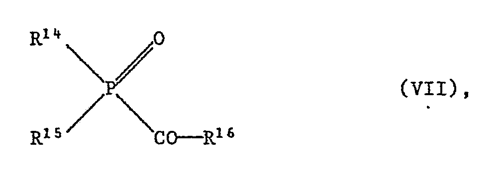
R¹⁴ C₁-C₆-Alkyl, C₅-C₆-Cycloalkyl, unsubstituiertes oder durch Halogen, Alkyl oder Alkoxy substituiertes C₆-C₁₀-Aryl oder ein S oder N enthaltender 5- oder 6-gliedriger heterocyclischer Rest ist,
R¹⁵ eine der für R¹⁴ gegebenen Bedeutungen hat oder C₁-C₆-Alkoxy, C₆-C₁₀-Aryloxy oder C₇-C₁₀-Aralkyloxy ist, oder R¹⁴ und R¹⁵ zusammen mit dem P-Atom einen Ring bilden und
R¹⁶ ein C₂-C₁₈-Alkylrest, ein C₂-C₄-Alkenylrest, ein C₅-C₁₂ cycloaliphatischer Rest, ein durch Alkyl, Alkoxy oder Alkylthio substituierter Phenyl- oder Naphthylrest oder ein S oder N enthaltender 5- oder 6-gliedriger heterocyclischer Rest ist oder eine Gruppe -Z-CO-P(O)(R¹⁴)(R¹⁵) ist, worin Z Phenylen oder C₂-C₆-Alkylen bedeutet.
- 1) Aroyl ketals of the formula III
Ar¹ is phenyl or phenyl substituted by C₁-C₄-alkyl or halogen,
Ar² has one of the meanings given for Ar¹ or is hydrogen, C₁-C₈-alkyl or C₅-C₈-cycloalkyl,
R³ and R⁴ independently of one another are C₁-C₆-alkyl, C₃-C₄-alkenyl, C₇-C₁₀-phenylalkyl or C₂-C₄-alkyl substituted by halogen, C₁-C₄-alkoxy, C₂-C₈-dialkylamino, morpholino or piperidino, or R³ and R⁴ together are C₂-C₁₂-alkanediyl or 2-butene-1,4-diyl.
Such compounds are known from US Pat. Nos. 3,715,293, 3,998,712, 4,485,249 and GB Pat. No. 1,390,006. - 2) Benzoin derivatives of the formula IV
Ar¹ is phenyl or phenyl substituted by C₁-C₄-alkyl or halogen,
R⁵ is hydrogen, C₁-C₄-alkyl, allyl, benzyl, hydroxymethyl or (C₁-C₄-alkoxy) methyl,
R⁶ is hydrogen, C₁-C₆-alkyl, C₃-C₈-alkoxyalkyl, allyl or benzyl or R⁵ and R⁶ together are -CH₂-O-CH₂-, -CH₂-OC (CH₃) ₂- or -CH₂-O-CH (C₆H₅ ) - mean.
Such compounds are described, for example, in German Patents 1,694,149 and 1,923,266. - 3) Acetophenone derivatives of the formula V
Ar³ phenyl or by one or more of the radicals halogen, C₁-C₁₈-alkyl, C₃-C₁₂-alkenyl, C₁-C₁₂-alkoxy, C₁-C₁₂-alkylthio, C₁-C₁₂-alkylamino, C₂-C₂₄-dialkylamino, C₄-C₈ Bis (hydroxyalkyl) amino, Phenoxy, phenylthio, 4-tolylthio, 2-hydroxyethylthio, allyloxy, allylthio, diallylamino, bis (2-methoxyethyl) amino, morpholino, piperidino or pyrrolidino means substituted phenyl,
R⁷ and R⁸ independently of one another are C₁-C₈-alkyl or C₁-C₄-alkyl substituted by OH, C₁-C₄-alkoxy, benzyloxy, -CN, -COO (C₁-C₈-alkyl), C₂-C₈-dialkylamino or morpholino, or R⁷ and R⁸ together are C₂-C₉-alkanediyl, (C₁-C₄-alkoxy) -pentanediyl-1,5, C₃-C₉-oxa- or azaalkanediyl or C₅-C₉-alkenediyl and
Y is a group -OR⁹ or -NR¹⁰R¹¹, wherein R⁹ is hydrogen, C₁-C₈-alkyl, C₂-C₄-alkyl substituted by OH, C₁-C₄-alkoxy or CN, allyl, benzyl or trimethylsilyl or R⁹ and R⁷ together are a group -CH₂-O-CH₂-, -C (CH₃) ₂-O-CH₂-, -CH (CH₃) -O-CH₂- or -CH (C₆H₅) -O-CH₂- mean and R¹⁰ and R¹¹ are independently hydrogen, C₁-C₁₂-alkyl, C₂-C₄-alkyl substituted by OH, C₁-C₄-alkoxy, -CN or -COO (C₁-C₄-alkyl), allyl, benzyl or cyclohexyl or R¹⁰ and R¹¹ together are C₃-C₇-alkanediyl mean, which can be interrupted by -O- or -NR¹²-, where R¹² is hydrogen, C₁-C₄-alkyl or C₂-C₄-hydroxyalkyl. Such compounds are described, for example, in DE-OS 2 722 264 and EP-A-3002. - 4) esters of arylglyoxylic acids of the formula VI
R¹³―-―OR¹² (VI).
wherein
R¹² is an unbranched or branched aliphatic C₁-C₁₀ hydrocarbon radical, phenyl, benzyl, cyclohexyl or trimethylsilyl and
R¹³ is unsubstituted C₆-C₁₄ aryl or phenyl substituted by one or more of the groups alkyl, alkoxy, aryloxy, alkylthio, arylthio or halogen.
R¹² as an aliphatic radical can be, for example, methyl, ethyl, propyl, butyl, pentyl, hexyl, 2-ethylbutyl, octyl, 2-ethylhexyl, nonyl, decyl, allyl or methallyl. R13 can be, for example, phenyl, diphenylyl, naphthyl, anthracyl, tolyl, xylyl, methoxyphenyl, phenoxyphenyl or chlorophenyl. Such compounds are described, for example, in US Pat. Nos. 4,038,164 and 4,519,883. - 5) Acylphosphine oxides of the formula VII
R¹⁴ is C₁-C₆-alkyl, C₅-C₆-cycloalkyl, unsubstituted or substituted by halogen, alkyl or alkoxy, C₆-C₁₀-aryl or a 5- or 6-membered heterocyclic radical containing S or N,
R¹⁵ has one of the meanings given for R¹⁴ or is C₁-C₆ alkoxy, C₆-C₁₀ aryloxy or C₇-C₁₀ aralkyloxy, or R¹⁴ and R¹⁵ together with the P atom form a ring and
R¹⁶ is a C₂-C₁₈ alkyl radical, a C₂-C₄ alkenyl radical, a C₅-C₁₂ cycloaliphatic radical, a phenyl or naphthyl radical substituted by alkyl, alkoxy or alkylthio or a 5- or 6-membered heterocyclic radical containing S or N or is a group -Z-CO-P (O) (R¹⁴) (R¹⁵), wherein Z is phenylene or C₂-C₆-alkylene.
Bevorzugt ist R¹⁶ ein tertiärer C₄-C₁₂-Alkylrest oder ein aromatischer oder heterocyclischer Rest, der in beiden Orthostellungen zur Bindung an die Carbonylgruppe durch je eine Gruppe Alkyl, Alkoxy oder Alkylthio substituiert ist.R¹⁶ is preferably a tertiary C₄-C₁₂ alkyl radical or an aromatic or heterocyclic radical which is substituted in each of the two ortho positions for binding to the carbonyl group by an alkyl, alkoxy or alkylthio group.
Die Verbindungen der Formel VII sind tertiäre Acylphosphinoxide oder Acylphosphinsäure-ester. Sie sind z.B. in den US-PS 4,265,723 und 4,292,152 beschrieben.The compounds of formula VII are tertiary acylphosphine oxides or acylphosphinic acid esters. They are described, for example, in US Pat. Nos. 4,265,723 and 4,292,152.
Geeignete Metallocen-Photoinitiatoren sind z.B. in EP-A 94 914, EP-A 94 915, EP-A 126 712, EP-A 152 377, EP-A 207 889 und EP-A 122 223 beschrieben. Geeignete Titanocene sind insbesondere in der EP-A 186 626 offenbart.Suitable metallocene photoinitiators are e.g. in EP-A 94 914, EP-A 94 915, EP-A 126 712, EP-A 152 377, EP-A 207 889 and EP-A 122 223. Suitable titanocenes are disclosed in particular in EP-A 186 626.
Die erfindungsgemäss einsetzbaren Pulverlacke können ferner noch Weichmacher, wie Dibutylphthalat, Dioctylphthalat oder Trikresylphosphat, oder sonstige Additive enthalten, wie Streckmittel, Füllstoffe und Färbemittel. Geeignete Streckmittel und Füllstoffe sind beispielsweise Glimmer, Tonerde, Gips, Talk, Titandioxid, Kreide, Quarzmehl, Cellulose, Kaolin, gemahlener Dolomit, Wollastonit, Kieselerde mit grosser spezifischer Oberfläche (erhältlich unter dem Handelsnamen "Aerosil"), mit langkettigen Aminen modifizierte Tonerde (erhältlich unter dem Handelsnamen "Bentone"), gepulvertes Polyvinylchlorid, Polyolefine oder Aminoplaste sowie Metallpulver, wie Kupfer-, Silber-, Aluminium- oder Eisenpulver. Flammschutzmittel, wie Antimontrioxid, können ebenfalls den härtbaren Mischungen zugegeben werden.The powder coating materials which can be used according to the invention may also contain plasticizers, such as dibutyl phthalate, dioctyl phthalate or tricresyl phosphate, or other additives, such as extenders, fillers and colorants. Suitable extenders and fillers are, for example, mica, alumina, gypsum, talc, titanium dioxide, chalk, quartz powder, cellulose, kaolin, ground dolomite, wollastonite, silica with a large specific surface area (available under the trade name "Aerosil"), alumina modified with long-chain amines ( available under the trade name "Bentone"), powdered polyvinyl chloride, polyolefins or aminoplasts and metal powder, such as copper, silver, aluminum or iron powder. Flame retardants such as antimony trioxide can also be added to the curable mixtures.
Den Pulverlacken können noch weitere in der Lackindustrie übliche Zusätze, wie beispielsweise Lichtschutzmittel, und insbesondere Entgasungsmittel, Verlaufsmittel thermische Härter, Füllstoffe und/oder Pigmente beigegeben werden.Further additives customary in the coating industry, such as, for example, light stabilizers, and in particular degassing agents, leveling agents, thermal hardeners, fillers and / or pigments can be added to the powder coatings.
Verlaufsmittel sind z.B. Polyvinylactale, wie Polyvinylbutyral ("Mowital" B 30 H® der HOECHST), Polyethylenglykol, Polyvinylpyrrolidon, Glycerin, Neopentylglykol, Acryl-Mischpolymerisate, wie "Modaflow"® oder "Acrylron" MFP® der MONSANTO bzw. der PROTEX, sowie "Acronal" 4F® der Firma BASF und "Uresin B® der Firma HOECHST (ein Carbamidsäureharz aus Butylurethan und Formaldehyd).Leveling agents are e.g. Polyvinyl lactals, such as polyvinyl butyral ("Mowital" B 30 H® from HOECHST), polyethylene glycol, polyvinyl pyrrolidone, glycerin, neopentyl glycol, acrylic copolymers, such as "Modaflow" ® or "Acrylron" MFP® from MONSANTO or PROTEX, as well as "Acronal" 4F® from BASF and "Uresin B® from HOECHST (a carbamic acid resin made from butyl urethane and formaldehyde).
Als Entgasungsmittel wird vorzugsweise Benzoin eingesetzt.Benzoin is preferably used as the degassing agent.
Als Füllstoff wird insbesondere Talk bevorzugt.Talc is particularly preferred as filler.
Die Pulverlacke können durch einfaches Mischen der Bestandteile, z.B. in einer Kugelmühle, hergestellt werden. Eine andere Möglichkeit der Herstellung besteht darin, dass man die Bestandteile zusammen schmilzt, vorzugsweise in einem Extruder, wie z.B. in einem Buss-Kokneter, und dann die abgekühlte Masse zerkleinert. Die Mischungen weisen vorzugsweise eine Partikelgrösse im Bereich von 0,015 bis 500 µm, und insbesondere von 1 - 75 µm, auf.The powder coatings can be made by simply mixing the ingredients, e.g. in a ball mill. Another way of manufacturing is to melt the ingredients together, preferably in an extruder, e.g. in a Buss co-kneader, and then crushed the cooled mass. The mixtures preferably have a particle size in the range from 0.015 to 500 μm, and in particular from 1 to 75 μm.
Die neben den Komponenten (A) und (B) in Pulverlack enthaltenen Zusatzstoffe werden in der Regel in kleinen Mengen, bevorzugt bis 20 Gew. %, bezogen auf die Gesamtmischung, zugesetzt. Sie müssen mit den übrigen Bestandteilen der Mischung verträglich sein.The additives contained in powder coating in addition to components (A) and (B) are generally added in small amounts, preferably up to 20% by weight, based on the mixture as a whole. They must be compatible with the rest of the mixture.
Ferner können den Mischungen noch Katalysatoren, Beschleuniger und Härter beigegeben werden, insbesondere, wenn die Komponente (A) ein Epoxidharz ist. Diese Zusätze bewirken bei einer eventuellen thermischen Nachbehandlung eine Nachhärtung der Epoxidkomponente; gegebenenfalls erfolgt dieser Nachhärtungsschritt nach der Entwicklung des Photoresists. Geeignete Härter, welche im erfindungsgemässen Verfahren als Härter für Epoxidharze verwendet werden können, sind beispielsweise phenolische Hydroxylgruppen, Carboxylgruppen und insbesondere Carbonsäureanhydridgruppen enthaltende Verbindungen.Furthermore, catalysts, accelerators and hardeners can also be added to the mixtures, in particular if component (A) is an epoxy resin. In the event of a thermal aftertreatment, these additives cure the epoxy component; optionally, this post-curing step takes place after the development of the photoresist. Suitable hardeners which can be used in the process according to the invention as hardeners for epoxy resins are, for example, phenolic hydroxyl groups, carboxyl groups and in particular compounds containing carboxylic anhydride groups.
Die erfindungsgemäss zu verwendenden Pulverlacke enthalten bevorzugt 50 - 99,5 Gew. % der Komponente (A), 0,5 - 20 Gew.% des Photoinitaotrs (B) und 0 - 20 Gew. % der Zusatzstoffe. Dabei ergänzen sich die Anteile der einzelnen Komponenten jeweils zu 100 % und die Mengenangaben sind auf die Gesamtmenge bezogen.The powder coating materials to be used according to the invention preferably contain 50-99.5% by weight of component (A), 0.5-20% by weight of photoinitiator (B) and 0-20% by weight of the additives. The proportions of the individual components complement each other to 100% and the quantities are based on the total quantity.
Ganz besonders bevorzugt enthalten die Pulverlacke, bezogen auf die Gesamtmenge, 60 - 99 Gew.% der Komponente (A), 1 - 10 Gew % des Photoinitiators (B) und 0 - 15 Gew. der Zusatzstoffe.The powder coatings very particularly preferably contain, based on the total amount, 60-99% by weight of component (A), 1-10% by weight of photoinitiator (B) and 0-15% by weight of the additives.
Vorzugsweise hat der erfindungsgemäss zu verwendende Pulverlack einen Erweichungspunkt im Bereich von etwa 50 bis 150°C, insbesondere etwa 65 bis 110°C.The powder coating to be used according to the invention preferably has a softening point in the range from approximately 50 to 150 ° C., in particular approximately 65 to 110 ° C.
Die Schichtdicke des Pulverlackes kann nach Bedarf variiert werden. Bevorzugt werden Schichtdicken von ca. 20 bis 200 µm, insbesondere von 30 bis 100 µm.The layer thickness of the powder coating can be varied as required. Layer thicknesses of approximately 20 to 200 μm, in particular of 30 to 100 μm, are preferred.
Der Pulverlack wird erfindungsgemäss auf das, gegebenenfalls vorgeheizte, zu beschichtende Material, z.B. auf eine Leiterplatte, mittels einer der für die Beschichtung von Gegenständen mit Pulverlacken bekannten Methoden appliziert. Geeignete Beschichtungsverfahren sind beispielsweise das Wirbelsinterverfahren oder das in der DE-OS 24 11 629 beschriebene Verfahren (elektrostatisches Wirbelsintern). Das Aufbringen des Pulverlackes kann auch mit einer elektrostatischen Pulverspritzpistole bei Spannungen von vorzugsweise 30 - 100, insbesondere 40 - 80 kV erfolgen. Dabei wird das zu beschichtende Material vorzugsweise auf eine Temperatur von über 100°C, insbesondere etwa 150 bis 200°C, vorgeheizt. Nach erfolgter Beschichtung wird das Material noch etwa 1 bis 5 Minuten bis zum Schmelzen des Pulvers zu einem porenfreien Film erwärmt. Der Film ist nach Abkühlung fest und klebfrei und kann z.B. zur Herstellung einer Lötstoppmaske belichtet werden.According to the invention, the powder coating is applied to the material to be coated, if appropriate preheated, e.g. applied to a circuit board using one of the methods known for coating objects with powder coatings. Suitable coating methods are, for example, the vortex sintering method or the method described in DE-OS 24 11 629 (electrostatic vortex sintering). The powder coating can also be applied with an electrostatic powder spray gun at voltages of preferably 30-100, in particular 40-80 kV. The material to be coated is preferably preheated to a temperature of above 100 ° C., in particular approximately 150 to 200 ° C. After coating, the material is heated for about 1 to 5 minutes until the powder melts to form a non-porous film. After cooling, the film is firm and tack-free and can e.g. be exposed to produce a solder mask.
Die Lichtempfindlichkeit der erfindungsgemäss verwendeten Pulverlacke reicht in der Regel von UV-Gebiet (ca. 200 nm) bis ca. 600 nm und umspannt somit einen sehr breiten Bereich. Bevorzugte Anwendung findet aktinische Strahlung einer Wellenlänge im Bereich von etwa 300 bis 550 nm. Als Lichtquellen kommt daher eine grosse Anzahl der verschiedensten Typen zur Anwendung. Es sind sowohl Punktquellen als auch flächenförmige Strahler (Lampenteppiche) geeignet. Beispiele sind: Kohlelichtbogenlampen, Xenon-Lichtbogenlampen, Quecksilberdampflampen, gegebenenfalls mit Metall-Halogeniden dotiert (Metall-Halogenlampen), Fluoreszenzlampen, Argonglühlampen, Elektronenblitzlampen und photographische Flutlichtlampen.The light sensitivity of the powder coating materials used according to the invention generally ranges from the UV region (approx. 200 nm) to approx. 600 nm and thus spans a very wide range. Preferred application is actinic radiation with a wavelength in the range of approximately 300 to 550 nm. A large number of the most varied types are therefore used as light sources. Both point sources and flat spotlights (lamp carpets) are suitable. Examples are: carbon arc lamps, xenon arc lamps, mercury vapor lamps, optionally doped with metal halides (metal halogen lamps), fluorescent lamps, argon incandescent lamps, electron flash lamps and photographic floodlights.
Der Abstand zwischen Lampe und erfindungsgemässem Bildmaterial kann je nach Anwendungszweck und Lampentyp bzw. -stärke variieren, z.B. zwischen 2 cm bis 150 cm. Speziell geeignet sind Laserlicht quellen, z.B. Argonionenlaser oder Kryptonionenlaser mit starken Emissionslinien (Ar-Laser) bei 457, 476, 488, 514, 528 nm. Bei dieser Art der Belichtung ist keine Photomaske im Kontakt mit der Photopolymerschicht mehr nötig; der gesteuerte Laser-Strahl schreibt direkt auf die Schicht. Hier ist die hohe Empfindlichkeit der erfindungsgemässen Materialien sehr vorteilhaft, die hohe Schreibgeschwindigkeiten bei relativ niedrigen Intensitäten erlaubt.The distance between the lamp and the image material according to the invention can vary, for example between 2 cm and 150 cm, depending on the application and the lamp type or intensity. Laser light is particularly suitable sources, eg argon ion laser or krypton ion laser with strong emission lines (Ar laser) at 457, 476, 488, 514, 528 nm. With this type of exposure, a photomask in contact with the photopolymer layer is no longer necessary; the controlled laser beam writes directly on the layer. The high sensitivity of the materials according to the invention, which allows high writing speeds at relatively low intensities, is very advantageous here.
Nach der bildmässigen Belichtung des Materials und vor der Entwicklung kann es vorteilhaft sein, für kürzere Zeit eine thermische Behandlung durchzuführen. Dabei werden nur die bereits belichteten Teile thermisch gehärtet. Diese thermische Behandlung ist besonders empfehlenswert bei den Metallocen-Photoinitiatoren. Sie kann in konventionellen Oefen, beispielsweise in Konvektionsöfen, stattfinden, aber auch mit IR-Strahlung, beispielsweise durch Bestrahlung mit IR-Lasern, oder in Mikrowellengeräten erfolgen. Die angewandten Temperaturen liegen im allgemeinen bei 50 - 150°C, bevorzugt bei 80 - 130°C; die Härtungszeit liegt in der Regel zwischen 5 und 40 Minuten.After the imagewise exposure of the material and before development, it can be advantageous to carry out a thermal treatment for a shorter time. Only the parts that have already been exposed are thermally hardened. This thermal treatment is particularly recommended for metallocene photoinitiators. It can take place in conventional ovens, for example in convection ovens, but also with IR radiation, for example by irradiation with IR lasers, or in microwave devices. The temperatures used are generally 50-150 ° C, preferably 80-130 ° C; the curing time is usually between 5 and 40 minutes.
Nach der Belichtung und gegebenenfalls thermischen Nachbehandlung werden die unbelichteten Stellen des Photolackes in an sich bekannter Weise mit einem Entwickler entfernt.After the exposure and, if appropriate, thermal aftertreatment, the unexposed areas of the photoresist are removed in a manner known per se using a developer.
Die Entwicklung erfolgt mit einer basischen wässrigen Lösung oder vorzugsweise mit organischen Lösungmitteln. In Frage kommen beispielsweise 2-Ethoxyethanol, Aceton, Methyl, Ethyl-Keton, γ-Butyrolacton, Benzylalkohol, n-Butyldiglykol (Diethylenglykolmonobutylether), Propylencarbonat und insbesondere Cyclohexanon sowie Mischungen dieser Lösungsmittel.Development takes place with a basic aqueous solution or preferably with organic solvents. For example, 2-ethoxyethanol, acetone, methyl, ethyl ketone, γ-butyrolactone, benzyl alcohol, n-butyl diglycol (diethylene glycol monobutyl ether), propylene carbonate and especially cyclohexanone and mixtures of these solvents.
Nach der Belichtung und Entwicklung kann das Reliefbild nochmals einer thermischen Behandlung unterworfen werden. Diese erfolgt vorzugsweise bei 80 - 160°C, insbesondere bei 110 - 150°C während 10 bis 120 Minuten. Dabei reagieren verbleibende, noch nicht umgesetzte reaktive Gruppen.After the exposure and development, the relief image can be subjected to a thermal treatment again. This is preferably carried out at 80-160 ° C, in particular at 110-150 ° C for 10 to 120 minutes. The remaining, unreacted reactive groups react.
Durch diese zusätzliche thermische Netzwerkbildung werden besonders resistente und dauerhafte Reliefbilder erhalten, die sich durch gute thermomechanische, chemische und elektrische Eigenschaften, insbesondere Stabilität, Haftung und hohen spezifischen Durchgangswiderstand auszeichnen.As a result of this additional thermal network formation, particularly resistant and permanent relief images are obtained which are distinguished by good thermomechanical, chemical and electrical properties, in particular stability, adhesion and high specific volume resistance.
Der Begriff 'Belichtung mit einem vorbestimmten Muster aktinischer Strahlung' beinhaltet sowohl die Belichtung durch eine Photomaske, die ein vorbestimmtes Muster enthält, beispielsweise ein Diapositiv, sowie die Belichtung durch einen Laserstrahl, der beispielsweise computergesteuert über die Oberfläche des beschichteten Substrates bewegt wird und auf diese Weise ein Bild erzeugt.The term 'exposure to a predetermined pattern of actinic radiation' includes both exposure through a photomask which contains a predetermined pattern, for example a slide, and exposure with a laser beam which is moved, for example, under computer control over and onto the surface of the coated substrate Way creates an image.
In den folgenden Beispielen wird die Erfindung näher erläutert.The invention is explained in more detail in the following examples.
Der in den Beispielen erwähnte Löttest wird wie folgt durchgeführt: Auf die ausgehärtete Prüfplatte wird eine Flussmittellösung aus 26 g Rein-Kolophonium und 100 ml Isopropanol mit einem Pinsel dünn aufgetragen und mindestens 20 min bei Raumtemperatur getrocknet. Die derart vorbehandelte Prüfplatte wird mit der zu prüfenden Lackschicht nach unten gerichtet auf ein bei 270 ± 5°C gehaltenes Lötbad (bestehend aus 50 % Blei und 50 % Zinn) gelegt. Nach 10 s wird die Prüfplatte vom Lötbad entfernt und leicht abgeschüttelt. Nach etwa 1 h Abkühlung wird das Flussmittel durch zweimaliges Waschen mit Isopropanol entfernt, und die Prüfplatte wird nach dem Trocknen (Abblasen mit Pressluft) mit Hilfe einer Stereolupe beurteilt. Um dem Löttest zu genügen, darf der Lack weder abheben oder abplatzen, noch Risse, Blasen oder Poren zeigen oder Zinnrückstände, wie Perlen oder Zinnschleier, aufweisen.The soldering test mentioned in the examples is carried out as follows: A flux solution of 26 g of pure rosin and 100 ml of isopropanol is thinly applied to the hardened test plate and dried at room temperature for at least 20 min. The test plate pretreated in this way is placed with the lacquer layer to be tested facing downward on a solder bath (consisting of 50% lead and 50% tin) kept at 270 ± 5 ° C. After 10 s the test plate is removed from the solder bath and shaken off gently. After cooling for about 1 hour, the flux is removed by washing twice with isopropanol, and the test plate is assessed after drying (blowing off with compressed air) using a stereo magnifier. In order to meet the soldering test, the paint must not lift off or flake off, show cracks, bubbles or pores, or have tin residues such as pearls or tin veils.
Die in den Ausführungsbeispielen verwendeten Photoinitiatoren entsprechen folgenden Verbindungen.
Photoinitiator I: (η⁶-1-Methylnaphthalin) (η⁵-cyclopentadienyl)-eisen(II)-hexafluorphosphat
Photoinitiator II: (η⁶-Stilben) (η⁵-cyclopentadienyl)eisen(II)-hexafluorphosphat
Photoinitiator III: (η⁶-Cumol) (η⁵-cyclopentadienyl)eisen(II)-hexafluorantimonat
Photoinitiator IV: BenzildimethylketalThe photoinitiators used in the exemplary embodiments correspond to the following compounds.
Photoinitiator I: (η⁶-1-methylnaphthalene) (η⁵-cyclopentadienyl) iron (II) hexafluorophosphate
Photoinitiator II: (η⁶-stilbene) (η⁵-cyclopentadienyl) iron (II) hexafluorophosphate
Photoinitiator III: (η⁶-cumene) (η⁵-cyclopentadienyl) iron (II) hexafluoroantimonate
Photoinitiator IV: benzil dimethyl ketal
Eine Mischung aus
1850 g eines technischen Kresol-Novolak Epoxidharzes mit einem Epoxidgehalt von 4,25 Aequ./kg und einem Erweichungspunkt von 99°C
100 g eines Verlaufsmittelkonzentrates bestehend aus 90 % Bisphenol-A-Harz und 10 % Acrylron MFP (ein Acryl-Mischpolymerisat der Fa. PROTEX), mit einem Epoxidgehalt von 1,25 Aequ./kg
50 g Photoinitiator I
240 g Talk und
20 g Grünpigment (Heliogengrün der BASF)
wird in einem Kneter PR 46 (Firma Buss AG) aufgeschmolzen. Nach dem Abkühlen der Schmelze wird die Masse zu einem feinen Pulver vermahlen. Der so erhaltene Pulverlack weist einen Erweichungspunkt (Koflerbank) von 75 - 95°C auf. Der Pulverlack wird mit einer elektrostatischen Pulverspritzpistole (Type 705 Ransburg-GEMA AG) bei einer Spannung von 80 kV auf eine mit Kupferleiterbahnen versehene Epoxidglasfaserplatte gespritzt. Die Platte wird vor dem Spritzen auf ca. 175°C aufgewärmt und in der Sprühkabine so aufgehängt, dass einige grössere Kupferleiterbahnen mit der Erdung der Sprühpistole elektrisch verbunden sind. Es entsteht sowohl auf den Leiterbahnen als auch auf der Isolierplatte eine zusammhängende Pulverschicht, die nach einem Aufschmelzprozess von 90 s bei 175°C zu einem porenfreien Film von ca. 50 µm Filmdicke schmilzt. Die Leiterbahnen sind in die Pulverlackschicht eingebettet und die durchkontaktierten Bohrungen von ca. 0,6 mm Durchmesser sind frei von Pulverlack.A mix of
1850 g of a technical cresol novolak epoxy resin with an epoxy content of 4.25 equivalents / kg and a softening point of 99 ° C
100 g of a leveling agent concentrate consisting of 90% bisphenol A resin and 10% Acrylron MFP (an acrylic copolymer from PROTEX), with an epoxy content of 1.25 equivalents / kg
50 g photoinitiator I
240 g talc and
20 g green pigment (heliogen green from BASF)
is melted in a kneader PR 46 (company Buss AG). After the melt has cooled, the mass is ground to a fine powder. The powder coating thus obtained has a softening point (Koflerbank) of 75-95 ° C. The powder coating is sprayed with an electrostatic powder spray gun (Type 705 Ransburg-GEMA AG) at a voltage of 80 kV onto an epoxy glass fiber plate provided with copper conductors. Before spraying, the plate is warmed up to approx. 175 ° C and suspended in the spray booth in such a way that some larger copper conductor tracks are electrically connected to the grounding of the spray gun. A coherent powder layer is formed both on the conductor tracks and on the insulating plate, which melts after a melting process of 90 s at 175 ° C. to form a pore-free film with a film thickness of approx. 50 µm. The Conductor tracks are embedded in the powder coating layer and the plated-through holes of approx. 0.6 mm diameter are free of powder coating.
Diese Platte wird durch eine Maske mit einer Metallhalogenid-Lampe von 5000 W im Abstand von 75 cm während 120 s belichtet. Danach wird die Platte 15 Min auf 110°C erwärmt, nach dem Abkühlen mit Cyclohexanon entwickelt und anschliessend während 1 Stunde bei 135°C nachgehärtet.This plate is exposed through a mask with a metal halide lamp of 5000 W at a distance of 75 cm for 120 s. The plate is then heated to 110 ° C. for 15 minutes, developed after cooling with cyclohexanone and then post-cured at 135 ° C. for 1 hour.
Die so behandelte Leiterplatte zeigt keine sichtbare Veränderung nach dem Löttest.The printed circuit board treated in this way shows no visible change after the soldering test.
Es wird ein Pulverlack analog zu Beispiel I hergestellt, wobei jedoch die Verbindung II anstelle von I als Photoinitiator eingesetzt wird.A powder coating is prepared analogously to Example I, but compound II is used instead of I as a photoinitiator.
Dieser Pulverlack wird mit einer Elektrostatik-Pulverspritzpistole mit 40 kV auf eine auf 160°C vorgewärmte Leiterplatte gespritzt. Nach dem Aufschmelzen während 90 s bei 160°C erhält man eine gleichmässige Schicht sowohl auf den Leiterbahnen als auch auf dem Isoliermaterial. Diese Leiterplatte wird wie in Bsp. 1 beschrieben während 60 s belichtet, vorgehärtet, entwickelt, nachgehärtet und dem Löttest ausgesetzt. Es wird keine sichtbare Veränderung der Resistschicht beobachtet.This powder coating is sprayed with a 40 kV electrostatic powder spray gun onto a circuit board preheated to 160 ° C. After melting at 160 ° C for 90 s, a uniform layer is obtained both on the conductor tracks and on the insulating material. As described in Example 1, this printed circuit board is exposed for 60 s, pre-hardened, developed, post-hardened and subjected to the soldering test. No visible change in the resist layer is observed.
Eine Mischung aus
935 g eines technischen, bromierten Epoxidphenolnovolaks mit einem Epoxidgehalt von 3,7 Aequ./kg mit einem Bromgehalt von 36 Gew. %
50 g des im Beispiel 1 verwendeten Verlaufsmittelkonzentrates
10 g Photoinitiator III
240 g Talk
10 g Grünpigment (Irgalithgrün GLN, CIBA-GEIGY)
wird im Kneter bei einer Manteltemperatur von 80°C aufgeschmolzen. Nach dem Mahlen (Korngrösse ca. 10-100µm) wird der Pulverlack (Schmelzbereich 107 - 110°C) mit der elektrostatischen Pulverspritzpistole (80 kV) auf eine 180°C vorgewärmte Leiterplatte gespritzt. Nach dem Aufschmelzen des Pulverlacks (90 s 180°C) wird ein zusammenhängender Film von ca. 80 µm mit guter Einbettung der Leiterbahnen erhalten.A mix of
935 g of a technical, brominated epoxy phenol novolak with an epoxy content of 3.7 equiv./kg with a bromine content of 36% by weight
50 g of the leveling agent concentrate used in Example 1
10 g photoinitiator III
240 g talc
10 g green pigment (irgalite green GLN, CIBA-GEIGY)
is melted in the kneader at a jacket temperature of 80 ° C. After grinding (grain size approx. 10-100µm), the powder coating (melting range 107 - 110 ° C) is sprayed with the electrostatic powder spray gun (80 kV) onto a preheated circuit board at 180 ° C. After the powder coating has melted (90 s 180 ° C.), a coherent film of approximately 80 μm is obtained with good embedding of the conductor tracks.
Diese Leiterplatte wird wie in Bsp. 1 beschrieben während 60 s belichtet, vorgehärtet, entwickelt, nachgehärtet und dem Löttest ausgesetzt. Es wird keine sichtbare Veränderung der Resistschicht beobachtet.
As described in Example 1, this printed circuit board is exposed for 60 s, pre-hardened, developed, post-hardened and subjected to the soldering test. No visible change in the resist layer is observed.
900 g eines Epoxidacrylates, welches durch Veresterung von 86,3 Teilen eines technischen Bisphenol-A-Epoxidharzes mit einem Epoxidgehalt von 2,0 Aequ./kg und einem Erweichungsbereich von 65 - 75°C (Epikote 1001, Shell) mit 13,7 Teilen Acrylsäure nach dem in der GB-A 2 032 939 beschriebenen Verfahren hergestellt wurde,
50 g des im Beispiel 1 beschriebenen Verlaufsmittelkonzentrates
50 g Photoinitiator IV
240 g Talk
10 g Heliogengrün (BASF)
werden im Kneter bei einer Manteltemperatur von 60°C aufgeschmolzen. Nach dem Erstarren wird die Masse gemahlen und damit ein Pulverlack mit einem Erweichungsbereich von 67 - 84°C erhalten, der mit einer elektrostatischen Spritzpistole mit 80 kV Spannung auf eine 150°C vorgewärmte Leiterplatte gespritzt wird. Nach Aufschmelzen (2 Min/120°C) wird ein porenfreier Film mit guter Einbettung der Leiterbahnen erhalten.900 g of an epoxy acrylate, which by esterification of 86.3 parts of a technical bisphenol A epoxy resin with an epoxy content of 2.0 equiv./kg and a softening range of 65 - 75 ° C (Epikote 1001, Shell) with 13.7 Parts of acrylic acid were prepared by the process described in GB-A 2 032 939,
50 g of the leveling agent concentrate described in Example 1
50 g photoinitiator IV
240 g talc
10 g heliogen green (BASF)
are melted in the kneader at a jacket temperature of 60 ° C. After solidification, the mass is ground and a powder coating with a softening range of 67 - 84 ° C is obtained, which is sprayed onto a 150 ° C preheated circuit board with an electrostatic spray gun with 80 kV voltage. After melting (2 min / 120 ° C) a pore-free film with good embedding of the conductor tracks is obtained.
Diese Leiterplatte wird wie in Bsp. 1 beschrieben während 60 s belichtet, mit Cyclohexanon entwickelt und 30 Min bei 135°C ausgehärtet. Die Platte zeigt nach dem Löttest keine sichtbare Veränderung.This circuit board is exposed as described in Example 1 for 60 s, developed with cyclohexanone and cured at 135 ° C. for 30 minutes. The plate shows no visible change after the soldering test.
Eine Mischung aus
1850 g eines technischen Bisphenol-A-Epoxidharzes mit einem Epoxidgehalt von 1,3 Aequ./kg und einem Erweichungsbereich von 65-75°C
100 g des im Beispiel 1 verwendeten Verlaufsmittelkonzentrates
50 g Photoinitiator II
480 g Talk und
20 g Grünpigment (Heliogengrün der BASF)
wird in einem Kneter PR 46 (BUSS AG) aufgeschmolzen. Nach dem Erstarren der Schmelze wird die Masse fein vermahlen und Grobanteile mit Korngrössen > 100 µm werden ausgesiebt. Der Pulverlack weist einen Erweichungsbereich (Koflerbank) von 76 - 97°C auf. Der Pulverlack wird mit einer elektrostatischen Pulverspritzpistole (Typ 705 der RANSBURG-GEMA AG) bei einer Spannung von 80 kV auf eine doppelseitig mit einer Kupferfolie kaschierte Epoxidglasfaserplatte von 1,6 mm Dicke gespritzt. Diese Platte weist Bohrungen von 0,6 - 1 mm Durchmesser auf und wird vor der Beschichtung mit dem Pulverlack in einem chemischen Kupferbad zwecks Durchkontaktierung behandelt. Die mit dem Pulverlack beschichtete Platte wird während 90 s auf 175°C erwärmt. Es resultiert eine homogene Beschichtung von ca. 65 µm Dicke. Die Löcher sind im wesentlichen frei von Pulverlack, und durch eine galvanische Abscheidung von Kupfer kann das chemisch abgeschiedene Kupfer in den Lochwandungen auf die erforderliche Dicke verstärkt werden. Die Platte wird durch eine Maske belichtete, nachgehärtet und in Diethylenglykolmono-n-Butylether entwickelt. Es entsteht ein Bild mit einer guten Auflösung und steilen Flanken. Die Platte wird nach folgendem Arbeitsschema in einem galvanischen Kupferbad behandelt:
- Reinigen durch 1-minütiges Tauchen in eine Lösung von BUZ-R bei 25°C (Dr.Ing. Max Schlötter GmbH + Co.AG.),
- 1 Min mit Leitungswasser spülen,
- Anätzen in einer Lösung von 120 g ENPLATE AD485 (IMASA AG, Dällikon, Schweiz) und 20 ml konzentrierter Schwefelsäure pro Liter Wasser,
- Saures Kupferbad AC der Firma Erne AG, Dällikon, 75 Min bei ca. 25°C und einer Stromdichte von 3 A/dm²,
-Spülen mit Leitungswasser.A mix of
1850 g of a technical bisphenol A epoxy resin with an epoxy content of 1.3 equiv./kg and a softening range of 65-75 ° C
100 g of the leveling agent concentrate used in Example 1
50 g photoinitiator II
480 g talc and
20 g green pigment (heliogen green from BASF)
is melted in a kneader PR 46 (BUSS AG). After the melt has solidified, the mass is finely ground and coarse particles with grain sizes> 100 µm are sieved out. The powder coating has a softening range (Kofler bench) of 76 - 97 ° C. The powder coating is sprayed with an electrostatic powder spray gun (type 705 from RANSBURG-GEMA AG) at a voltage of 80 kV onto an epoxy glass fiber plate of 1.6 mm thickness laminated with copper foil. This plate has holes with a diameter of 0.6 - 1 mm and is treated in a chemical copper bath for through-contacting before coating with the powder coating. The plate coated with the powder coating is heated to 175 ° C. for 90 s. The result is a homogeneous coating with a thickness of approx. 65 µm. The holes are essentially free of powder coating, and the electrodeposited copper can be used to reinforce the chemically deposited copper in the hole walls to the required thickness. The plate is exposed through a mask, post-cured and developed in diethylene glycol mono-n-butyl ether. The result is an image with good resolution and steep flanks. The plate is treated in a galvanic copper bath according to the following working scheme:
- cleaning by immersion in a solution of BUZ-R at 25 ° C for 1 minute (Dr.Ing. Max Schlötter GmbH + Co.AG.),
- rinse with tap water for 1 min,
- Etching in a solution of 120 g ENPLATE AD485 (IMASA AG, Dällikon, Switzerland) and 20 ml concentrated sulfuric acid per liter water,
- Acid copper bath AC from Erne AG, Dällikon, 75 min at approx. 25 ° C and a current density of 3 A / dm²,
- Rinse with tap water.
Nach der galvanischen Behandlung der Platte weist der Galvanoresist keine Beschädigungen wie Blasen, Risse etc. auf und ist durch Strippen mit Methylenchlorid sauber entfernbar. Der erhaltene Kupferüberzug hat eine Dicke von ca. 50 µm.After the galvanic treatment of the plate, the galvanoresist shows no damage such as bubbles, cracks etc. and can be removed by stripping with methylene chloride. The copper coating obtained has a thickness of approximately 50 μm.
Eine Mischung aus
60 Gwt. (=Gewichtsteile) eines Epoxidacrylates, welches durch Umsetzung eines Epoxidharzes vom Bis-Phenol A-Typ mit einem Epoxidgehalt von 1,1 Aeq/kg und einem Erweichungsbereich von 75-85°C mit Acrylsäure hergestellt wurde und als technisches Produkt mit der Bezeichnung RIPOXY VR 60 von Showa Highpolymers in Japan erhältlich ist,
32,5 Gwt. des Urethanacrylates der Formel
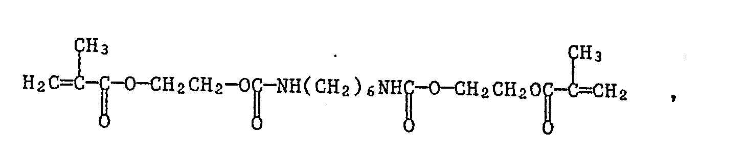
5 Gwt. eines Verlaufmittelkonzentrates bestehend aus 90 Gwt. des Epoxidacrylates RIPOXY VR 60 und 10 Gwt. ACRYLON MFP 250 (Acrylmischpolymerisat der Fa. PROTEX),
2,5 Gwt. Photoinitiator IV
0,5 Gwt. AEROSIL R972 (DEGUSSA)
wird während 8 Stunden in der Kugelmühle gemischt und fein vermahlen und dann durch ein Sieb von 100 µm Maschenweite gesiebt. Dieser Pulverlack wird mit einer elektrostatischen Spritzpistole auf ein Kupfer-Laminat beschichtet. Die mit dem Pulverlack beschichtete Platte wird während 4 Minuten auf 120°C erwärmt. Es entsteht ein gleichmässiger Film von ca. 50 µm Filmdicke.A mix of
60 pbw (= Parts by weight) of an epoxy acrylate, which was prepared by reacting an epoxy resin of the bis-phenol A type with an epoxy content of 1.1 Aeq / kg and a softening range of 75-85 ° C with acrylic acid and as a technical product with the name RIPOXY VR 60 is available from Showa Highpolymers in Japan,
32.5 pbw of the urethane acrylate of the formula
5 wwt. a leveling agent concentrate consisting of 90 pbw. of the epoxy acrylate RIPOXY VR 60 and 10 Gwt. ACRYLON MFP 250 (acrylic copolymer from PROTEX),
2.5 pbw Photoinitiator IV
0.5 pbw AEROSIL R972 (DEGUSSA)
is mixed and finely ground in a ball mill for 8 hours and then sieved through a sieve of 100 μm mesh size. This powder coating is coated with an electrostatic spray gun on a copper laminate. The plate coated with the powder coating is heated to 120 ° C. for 4 minutes. A uniform film of approx. 50 µm film thickness is created.
Die Platte wird wie in Beispiel 1 beschrieben durch eine Maske 30 Sekunden lang belichtet und anschliessend 10 Minuten auf 110°C erwärmt. Bei der nachfolgenden Entwicklung in einem Gemisch von 50 Gwt. Propylencarbonat, 30 Gwt. Diethylenglykolmonobutylether und 20 Gwt. γ-Butyrolacton wird ein Bild mit einer guten Auflösung erhalten.The plate is exposed for 30 seconds through a mask as described in Example 1 and then heated to 110 ° C. for 10 minutes. In the subsequent development in a mixture of 50 wt. Propylene carbonate, 30 pbw Diethylene glycol monobutyl ether and 20% by weight. γ-butyrolactone gives an image with a good resolution.
Eine Mischung aus
60 Gwt. des in Beispiel 6 benutzten Epoxidacrylates
32,5 Gwt. des Urethanacrylates der Formel

2,5 Gwt. Photoinitiator IV
5 Gwt. des in Beispiel 6 verwendeten Verlaufsmittelkonzentrates
0,5 Gwt. AEROSIL R972 (DEGUSSA)
0,2 Gwt. Kristallviolett
werden in einer Kugelmühle während 6 Stunden vermischt und fein vermahlen und dann durch ein Sieb von 100 µm Maschenweite gesiebt. Die Applikation und das Aufschmelzen erfolgt analog zum Beispiel 6. Man erhält einen gleichmässigen Film von ca. 60 µm Filmdicke. Nach der Belichtung und Entwicklung analog zum Beispiel 6 erhält man ein Bild mit einer guten Auflösung.A mix of
60 pbw of the epoxy acrylate used in Example 6
32.5 pbw of the urethane acrylate of the formula
2.5 pbw Photoinitiator IV
5 wwt. of the leveling agent concentrate used in Example 6
0.5 pbw AEROSIL R972 (DEGUSSA)
0.2 wt. Crystal violet
are mixed in a ball mill for 6 hours and finely ground and then sieved through a sieve with a mesh size of 100 μm. The application and melting takes place analogously to example 6. A uniform film of approximately 60 µm film thickness is obtained. After exposure and development analogous to example 6, an image with a good resolution is obtained.
Claims (16)
(A) eine strahlungshärtbare Verbindung und gegebenenfalls
(B) einen strahlungsaktivierbaren Polymerisationsinitiator für (A)
elektrostatisch beschichtet wird,
(A) a radiation curable compound and optionally
(B) a radiation-activatable polymerization initiator for (A)
is electrostatically coated,
CH₂=
enthält, worin R³ Wasserstoff, Chlor oder Brom oder eine C₁-C₄-Alkylgruppe ist.7. The method according to claim 6, wherein the compound (A) at least one group of formula II
CH₂ =
contains, wherein R³ is hydrogen, chlorine or bromine or a C₁-C₄ alkyl group.
Applications Claiming Priority (4)
| Application Number | Priority Date | Filing Date | Title |
|---|---|---|---|
| CH1314/87 | 1987-04-06 | ||
| CH131487 | 1987-04-06 | ||
| CH224587 | 1987-06-15 | ||
| CH2245/87 | 1987-06-15 |
Publications (1)
| Publication Number | Publication Date |
|---|---|
| EP0286594A2 true EP0286594A2 (en) | 1988-10-12 |
Family
ID=25687296
Family Applications (1)
| Application Number | Title | Priority Date | Filing Date |
|---|---|---|---|
| EP19880810207 Withdrawn EP0286594A2 (en) | 1987-04-06 | 1988-03-28 | Process for the production of photographically structurable coatings |
Country Status (2)
| Country | Link |
|---|---|
| EP (1) | EP0286594A2 (en) |
| JP (1) | JPS63261259A (en) |
Cited By (10)
| Publication number | Priority date | Publication date | Assignee | Title |
|---|---|---|---|---|
| WO1991003770A1 (en) * | 1989-09-11 | 1991-03-21 | Coates Brothers Plc | Resists |
| EP0541111A1 (en) * | 1991-11-06 | 1993-05-12 | Nippon Paint Co., Ltd. | Method of forming solder mask |
| US5368884A (en) * | 1991-11-06 | 1994-11-29 | Nippon Paint Co., Ltd. | Method of forming solder mask |
| EP0667381A2 (en) * | 1994-02-09 | 1995-08-16 | Ciba-Geigy Ag | Ultraviolet curable solid epoxy resin compositions |
| US5476749A (en) * | 1991-03-27 | 1995-12-19 | Ciba-Geigy Corporation | Photosensitive compositions based on acrylates |
| US5558911A (en) * | 1994-04-18 | 1996-09-24 | Basf Lacke + Farben Aktiengesellschaft | Coating articles using radiation-curable powder coatings |
| WO1997002511A1 (en) * | 1995-07-03 | 1997-01-23 | Ppg Industries, Inc. | Electrodepositable photoimageable compositions with improved edge coverage |
| US6747091B1 (en) | 1999-02-25 | 2004-06-08 | Basf Coatings Ag | Powder-slurry that can be hardened by actinic radiation or optionally by thermal means, method for producing said slurry and use of the same |
| EP1581034A1 (en) * | 2004-03-25 | 2005-09-28 | DSM IP Assets B.V. | Method of forming solder mask |
| US7122595B1 (en) | 1999-02-25 | 2006-10-17 | Basf Coatings Ag | Powder-slurry that can be hardened by actinic radiation or by thermal means, method for producing said slurry and use of the same |
Families Citing this family (7)
| Publication number | Priority date | Publication date | Assignee | Title |
|---|---|---|---|---|
| JPS6454442A (en) * | 1987-08-25 | 1989-03-01 | Nippon Soda Co | Photocurable resist resin composition for chemical plating |
| US4940651A (en) * | 1988-12-30 | 1990-07-10 | International Business Machines Corporation | Method for patterning cationic curable photoresist |
| US5667934A (en) * | 1990-10-09 | 1997-09-16 | International Business Machines Corporation | Thermally stable photoimaging composition |
| TW460509B (en) * | 1996-07-12 | 2001-10-21 | Ciba Sc Holding Ag | Curing process for cationically photocurable formulations |
| EP1125996A1 (en) * | 2000-02-09 | 2001-08-22 | Ucb, S.A. | Radiation curable powder compositions |
| US20070042191A1 (en) * | 2003-11-03 | 2007-02-22 | Carter James W | Tougher cycloaliphatic epoxide resins |
| JP5122078B2 (en) * | 2006-04-03 | 2013-01-16 | アイカ工業株式会社 | Decorative plate and manufacturing method thereof |
Family Cites Families (1)
| Publication number | Priority date | Publication date | Assignee | Title |
|---|---|---|---|---|
| JPS59160593U (en) * | 1983-04-15 | 1984-10-27 | 丸山 静子 | Clothes pill remover |
-
1988
- 1988-03-28 EP EP19880810207 patent/EP0286594A2/en not_active Withdrawn
- 1988-04-06 JP JP63084982A patent/JPS63261259A/en active Pending
Cited By (14)
| Publication number | Priority date | Publication date | Assignee | Title |
|---|---|---|---|---|
| WO1991003770A1 (en) * | 1989-09-11 | 1991-03-21 | Coates Brothers Plc | Resists |
| US5476749A (en) * | 1991-03-27 | 1995-12-19 | Ciba-Geigy Corporation | Photosensitive compositions based on acrylates |
| EP0711105A3 (en) * | 1991-11-06 | 1998-10-14 | Nippon Paint Co., Ltd. | Method of forming solder mask |
| US5368884A (en) * | 1991-11-06 | 1994-11-29 | Nippon Paint Co., Ltd. | Method of forming solder mask |
| EP0711105A2 (en) * | 1991-11-06 | 1996-05-08 | Nippon Paint Co., Ltd. | Method of forming solder mask |
| EP0541111A1 (en) * | 1991-11-06 | 1993-05-12 | Nippon Paint Co., Ltd. | Method of forming solder mask |
| EP0667381A2 (en) * | 1994-02-09 | 1995-08-16 | Ciba-Geigy Ag | Ultraviolet curable solid epoxy resin compositions |
| EP0667381A3 (en) * | 1994-02-09 | 1996-03-20 | Ciba Geigy Ag | Ultraviolet curable solid epoxy resin compositions. |
| US6001428A (en) * | 1994-02-09 | 1999-12-14 | Ciba Specialty Chemicals Corp. | Solid epoxy resin compositions crosslinkable with UV rays |
| US5558911A (en) * | 1994-04-18 | 1996-09-24 | Basf Lacke + Farben Aktiengesellschaft | Coating articles using radiation-curable powder coatings |
| WO1997002511A1 (en) * | 1995-07-03 | 1997-01-23 | Ppg Industries, Inc. | Electrodepositable photoimageable compositions with improved edge coverage |
| US6747091B1 (en) | 1999-02-25 | 2004-06-08 | Basf Coatings Ag | Powder-slurry that can be hardened by actinic radiation or optionally by thermal means, method for producing said slurry and use of the same |
| US7122595B1 (en) | 1999-02-25 | 2006-10-17 | Basf Coatings Ag | Powder-slurry that can be hardened by actinic radiation or by thermal means, method for producing said slurry and use of the same |
| EP1581034A1 (en) * | 2004-03-25 | 2005-09-28 | DSM IP Assets B.V. | Method of forming solder mask |
Also Published As
| Publication number | Publication date |
|---|---|
| JPS63261259A (en) | 1988-10-27 |
Similar Documents
| Publication | Publication Date | Title |
|---|---|---|
| EP0286594A2 (en) | Process for the production of photographically structurable coatings | |
| DE3613107C2 (en) | ||
| AT401265B (en) | ALKYL-BISACYLPHOSPHINOXIDES, THE COMPOSITIONS CONTAINING THEM AND THEIR USE | |
| EP0177453B1 (en) | Image-producing process | |
| EP0151372B1 (en) | Image production | |
| EP0003040B1 (en) | Light-sensitive coating material and process for the production of a negative photo resist image | |
| EP0075537B2 (en) | Process for coating printed circuits | |
| EP0255989B1 (en) | Negative photoresist on the basis of polyphenols and epoxide compounds or vinyl ethers | |
| JP2008509967A5 (en) | ||
| EP0418733B1 (en) | Radiation-curable composition and method of producing a solder mask | |
| EP0221010A1 (en) | Photo-initiator systems for free-radical polymerisations | |
| EP0207893B1 (en) | Image-forming process | |
| EP0182744B1 (en) | Radiation curable filled epoxy resin compositions and their use | |
| EP0302019A2 (en) | Negative photoresists on the basis of polyphenols and a choice of epoxide or vinyl ether compounds | |
| DE3331691A1 (en) | LIGHT-SENSITIVE, CURABLE MIXTURE SUITABLE FOR POSITIVE RECORDING MATERIAL | |
| EP0321828A2 (en) | Photopolymerisable mixture and recording material manufactured therefrom | |
| EP0295211B1 (en) | Photoresist composition | |
| JPH0368376B2 (en) | ||
| DE2557078C3 (en) | Photosensitive mass | |
| DE4142735A1 (en) | POLYMERIZABLE MIXTURE BY RADIATION AND METHOD FOR PRODUCING A SOLDER STOP MASK | |
| US5073478A (en) | Method of making a pattern | |
| EP0321827A2 (en) | Photopolymerisable mixture and recording material manufactured therefrom | |
| EP0291879B1 (en) | Photopolymerisable recording materials as well as photoresist layers and planographic printing plates on a basis of these recording materials as well as quinazolone-4 compounds | |
| EP0204292B1 (en) | Process for the production of printed circuits using a photopolymerisable system | |
| JP2868984B2 (en) | Circuit board |
Legal Events
| Date | Code | Title | Description |
|---|---|---|---|
| PUAI | Public reference made under article 153(3) epc to a published international application that has entered the european phase |
Free format text: ORIGINAL CODE: 0009012 |
|
| 17P | Request for examination filed |
Effective date: 19880330 |
|
| AK | Designated contracting states |
Kind code of ref document: A2 Designated state(s): CH DE FR GB IT LI NL SE |
|
| STAA | Information on the status of an ep patent application or granted ep patent |
Free format text: STATUS: THE APPLICATION IS DEEMED TO BE WITHDRAWN |
|
| 18D | Application deemed to be withdrawn |
Effective date: 19901003 |