EP0284311A2 - Block unit for making three-dimensional structures - Google Patents
Block unit for making three-dimensional structures Download PDFInfo
- Publication number
- EP0284311A2 EP0284311A2 EP88302413A EP88302413A EP0284311A2 EP 0284311 A2 EP0284311 A2 EP 0284311A2 EP 88302413 A EP88302413 A EP 88302413A EP 88302413 A EP88302413 A EP 88302413A EP 0284311 A2 EP0284311 A2 EP 0284311A2
- Authority
- EP
- European Patent Office
- Prior art keywords
- disk
- bar
- link
- central
- ring
- Prior art date
- Legal status (The legal status is an assumption and is not a legal conclusion. Google has not performed a legal analysis and makes no representation as to the accuracy of the status listed.)
- Withdrawn
Links
Images


Classifications
-
- A—HUMAN NECESSITIES
- A63—SPORTS; GAMES; AMUSEMENTS
- A63H—TOYS, e.g. TOPS, DOLLS, HOOPS OR BUILDING BLOCKS
- A63H33/00—Other toys
- A63H33/04—Building blocks, strips, or similar building parts
- A63H33/06—Building blocks, strips, or similar building parts to be assembled without the use of additional elements
- A63H33/08—Building blocks, strips, or similar building parts to be assembled without the use of additional elements provided with complementary holes, grooves, or protuberances, e.g. dovetails
-
- Y—GENERAL TAGGING OF NEW TECHNOLOGICAL DEVELOPMENTS; GENERAL TAGGING OF CROSS-SECTIONAL TECHNOLOGIES SPANNING OVER SEVERAL SECTIONS OF THE IPC; TECHNICAL SUBJECTS COVERED BY FORMER USPC CROSS-REFERENCE ART COLLECTIONS [XRACs] AND DIGESTS
- Y10—TECHNICAL SUBJECTS COVERED BY FORMER USPC
- Y10T—TECHNICAL SUBJECTS COVERED BY FORMER US CLASSIFICATION
- Y10T403/00—Joints and connections
- Y10T403/34—Branched
- Y10T403/341—Three or more radiating members
- Y10T403/342—Polyhedral
-
- Y—GENERAL TAGGING OF NEW TECHNOLOGICAL DEVELOPMENTS; GENERAL TAGGING OF CROSS-SECTIONAL TECHNOLOGIES SPANNING OVER SEVERAL SECTIONS OF THE IPC; TECHNICAL SUBJECTS COVERED BY FORMER USPC CROSS-REFERENCE ART COLLECTIONS [XRACs] AND DIGESTS
- Y10—TECHNICAL SUBJECTS COVERED BY FORMER USPC
- Y10T—TECHNICAL SUBJECTS COVERED BY FORMER US CLASSIFICATION
- Y10T403/00—Joints and connections
- Y10T403/34—Branched
- Y10T403/341—Three or more radiating members
- Y10T403/345—Coplanar
Definitions
- a block unit comprising a circular disk means and a ladder-shaped link means wherein each circular disk means may serve as a point or vertex and each link means may serve as a line section so that a diversified geometric polyhedron or an irregularly-shaped gigantic structure or skeleton can be assembled by assembling a plurality of the disk means and link means to include geometric points and lines to vividly mimic true articles or animals and enrich the player's interest.
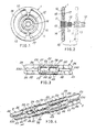
- the block unit of the present invention comprises: a circular disk means 1 and a ladder-shaped link means 2, each circular disk means 1 serving as a point or a vertex and each ladder-shaped link means 2 serving as a line section for a geometric shape.
- Each circular disk means 1 includes: an upper female socket 11 formed on a central portion of a central disk portion 10, a lower male screw 12 engageable with female socket 11 of another circular disk 1 and extending downwardly from the central disk portion 10 and secured to the disk portion by a neck portion 13, an inner ring 14 concentric to the center of the central disk portion 10 and formed on both upper and lower sides of the disk portion 10, a middle ring 15 concentric to the center of the disk portion 10 and formed on both sides of the disk portion 10 outside the inner ring 14, and outer ring 16 concentric to the center of disk portion 10 and spaced from the middle ring 15 by an annular groove 18 outside the middle ring 15 and connected to the ring 15 by a pair of radial connectors 17 across the annular groove 18.
- Each ladder-shaped link means 2 includes: a pair of parallel longitudinal bars 22 transversely connected by a central bar 21 perpendicular to the two longitudinal bars 22 and also transversely connected by a pair of side bars 27 each bar 27 positioned on an outer side of the central bar 21 and perpendicular to the two bars 22, having a pair of side clamps 23 disposed on two opposite ends of the two side bars 27.
- Each side clamp 23 includes an outer notch 24, a middle notch 25 and an inner notch 26 inwardly subsequently formed along a slit 230 recessed from the outermost end of each clamp 23.
- a pair of intermediate windows 28 are formed on two opposite sides of the central bar 21 each window 28 defined by the two longitudinal bars 22, each side bar 27 and the central bar 21.
- one link means 2 is coupled to the other link 2 by coupling one outer notch 24 of the right link 2 with the other side bar 27 (as shown in dotted line) of the left link 2, and the right link 2 can be further pushed leftwards to deeply couple the left link 2 until the inner notch 26 of the right link 2 engaging with the right side bar 27 of left link 2 (full line).
- Plural links 2 can be linearly assembled to form a geometric line or line section.
- one link 2 can be coupled to the circular disk 1 by engaging the notch 24 or 25 or 26 of the link 2 with the neck portion 13 of the circular disk 1.
- Another link 2 can be coupled to the radial connector 17 of the circular disk 1.
- Any notch 24 or 25 or 26 of the link 2 can be engaged with either ring 16 or 15 or 14 for circular movement of each link 2 along the perimeter of each ring.
- the link 2 having its outer notch 24 engaged with the ring 16 can be either horizontally moved along the ring perimeter (H) or vertically moved (V) along the intersection of the ring 16.
- the length of the slit 230 of each link clamp 23 should be long enough to allow all notches 24, 25, 26 operatively engaged with each ring 16 or 15 or 14 of the disk means 1, and should also be long enough so that one inner notch 26 of one link 2 may be deeply engaged with one side arm 27 of the other link 2.
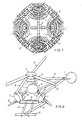
- each disk means 1 as a vertex and each link means 2 as a line section, a geometric shape of a tetrahedron can be assembled as shown in Figure 7.
- other polyhedra such as: six-face, 8-face, 12-face, 20-face, and other multiple-face polyhedron can be easily assembled.
- two circular disk means 1 can be overlain together to frictionally pressurize the neighbor link means 1 for stable construction of geometric shape.
- the coupling of two disks 1 can be adjusted for diversified geometric polyhedra.
- an irregularly-shaped skeleton such as a helicopter can be assembled in which the cabin of the helicopter is composed of a tetrahedron by plural circular disk means 1 and plural link means 2, the rotor blades are formed by engaging three linear assemblies each having three link means 2 fixed on a central circular disk means 1, and the tailrotor is formed by a circular disk means 1 rotatably mounted on a link means 2 which is then secured to the tetrahedron cabin by several linear arrangement of link means 2.
- a star-like plane is formed by assembling plural circular disk means 1 and plural link means 2. Since the link 2 can be optionally engaged with either ring 16 or 15 or 14 of the circular disk 1, the distance between every two neighboring points (i. e. two circular disks 1) can be conveniently adjusted for smoother connection of the two neighboring circular disks 1.
- the center point A is connected to a middle point B by a link 2 having the notch 24 of the inner end of the link 2 connected with the ring 14 of points A and having the other notch 24 of the outer end of the link 2 connected to the ring 14 of point B.
- the connecting link 2 has its left-end notch 24 connected with the ring 15 of left point B and has its right-end notch 24 connected with the ring 15 of right points B.
- the link 2, used to connect point B and point C, has an outer notch 24 of its one end connected with the ring 14 of point B and has the other outer notch 24 of its other end engaged with the ring 15 of point C.
Abstract
A block unit includes a circular disk (1) and a link (2) in which each link (2) can be horizontally or vertically engaged with a plurality of rings (14, 15, 16) formed on each disk (1) in any orientation so as to form a multiple-face polyhedron or an irregular shape by assembling a plurality of the disks (1) and links (2) to vividly form or mimic an animal, an article, a machine or any other geometric structures or gigantic skeletons.
Description
- Charles O. Perry disclosed Rhombic Hexahedra Blocks for making Rhombic Dodecahedra in his U. S. Patent 3,611,620, in which geometric toy blocks can be made by fitting four obtuse hexahedra together to have geometric shapes, and however have the following drawbacks:
- 1. Even many shapes of geometric polyhedra can be assembled, each polyhedron is assembled by assembling several individual polyhedron units different from each other. The production cost for molding the basic units such as cubical hexahedron, rhombic hexahedron or other shapes will be increased.
- 2. Every two neighboring blocks are coupled by a plurality of stems and spherical end portions. The steps as fixed inside each block may increase their production complexity and each stem may be broken or damaged after repeated services.
- 3. It is difficult to assemble an irregularly shaped toy blocks such as to mimic an animal, a machine or an article since they are lacking of linear linking elements or rotating elements, so that it is difficult to form diversified vivid gigantic structures.
- According to the present invention there is provided a block unit comprising a circular disk means and a ladder-shaped link means wherein each circular disk means may serve as a point or vertex and each link means may serve as a line section so that a diversified geometric polyhedron or an irregularly-shaped gigantic structure or skeleton can be assembled by assembling a plurality of the disk means and link means to include geometric points and lines to vividly mimic true articles or animals and enrich the player's interest.
- A specific embodiment of the present invention will now be described with reference to the accompanying drawings, in which:
- Figure 1 is a top view of a circular disk means of the present invention.
- Figure 2 is a sectional drawing showing a circular disk to be assembled with the other disk in accordance with the present invention.
- Figure 3 is an illustration of a ladder-shaped link means of the present invention.
- Figure 4 is an illustration showing the assembly of a link means with the other link in accordance with the present invention.
- Figure 5 shows still another application for the assembly of several link means of the present invention.
- Figure 6 shows the assembly of link means on a circular means of the present invention.
- Figure 7 shows a geometric tetrahedron assembled in accordance with the present invention.
- Figure 8 shows a helicopter assembled in accordance with the present invention.
- Figure 9 shows a star-like plane assembled in accordance with the present invention.
- Figure 10 is a partially enlarged illustration showing the assembly of a star plane as shown in Figure 9.
- As shown in Figures 1 - 3, the block unit of the present invention comprises: a circular disk means 1 and a ladder-shaped link means 2, each circular disk means 1 serving as a point or a vertex and each ladder-shaped link means 2 serving as a line section for a geometric shape.
- Each circular disk means 1 includes: an upper
female socket 11 formed on a central portion of acentral disk portion 10, alower male screw 12 engageable withfemale socket 11 of anothercircular disk 1 and extending downwardly from thecentral disk portion 10 and secured to the disk portion by aneck portion 13, aninner ring 14 concentric to the center of thecentral disk portion 10 and formed on both upper and lower sides of thedisk portion 10, amiddle ring 15 concentric to the center of thedisk portion 10 and formed on both sides of thedisk portion 10 outside theinner ring 14, andouter ring 16 concentric to the center ofdisk portion 10 and spaced from themiddle ring 15 by anannular groove 18 outside themiddle ring 15 and connected to thering 15 by a pair ofradial connectors 17 across theannular groove 18. - Each ladder-shaped link means 2 includes: a pair of parallel
longitudinal bars 22 transversely connected by acentral bar 21 perpendicular to the twolongitudinal bars 22 and also transversely connected by a pair ofside bars 27 eachbar 27 positioned on an outer side of thecentral bar 21 and perpendicular to the twobars 22, having a pair ofside clamps 23 disposed on two opposite ends of the twoside bars 27. Eachside clamp 23 includes anouter notch 24, amiddle notch 25 and aninner notch 26 inwardly subsequently formed along aslit 230 recessed from the outermost end of eachclamp 23. A pair ofintermediate windows 28 are formed on two opposite sides of thecentral bar 21 eachwindow 28 defined by the twolongitudinal bars 22, eachside bar 27 and thecentral bar 21. On the intermediate surface of eachlongitudinal bar 22, there is formed withcorrugations 29 to limit the longitudinal slipping of the assembled links. - In Figure 4, one link means 2 is coupled to the
other link 2 by coupling oneouter notch 24 of theright link 2 with the other side bar 27 (as shown in dotted line) of theleft link 2, and theright link 2 can be further pushed leftwards to deeply couple theleft link 2 until theinner notch 26 of theright link 2 engaging with theright side bar 27 of left link 2 (full line).Plural links 2 can be linearly assembled to form a geometric line or line section. - In Figure 5, other styles for assembling the
links 2 can be optionally done to form diversified geometric structure or skeleton. Any notch of thelink 2 should be able to engage with eithercentral bar 21, orside bar 27 orlongitudinal bar 22 in any direction of other link. - In Figure 6, one
link 2 can be coupled to thecircular disk 1 by engaging thenotch link 2 with theneck portion 13 of thecircular disk 1. Anotherlink 2 can be coupled to theradial connector 17 of thecircular disk 1. Anynotch link 2 can be engaged with eitherring link 2 along the perimeter of each ring. On theouter ring 16, thelink 2 having itsouter notch 24 engaged with thering 16 can be either horizontally moved along the ring perimeter (H) or vertically moved (V) along the intersection of thering 16. - From the aforementioned, the length of the
slit 230 of eachlink clamp 23 should be long enough to allow allnotches ring inner notch 26 of onelink 2 may be deeply engaged with oneside arm 27 of theother link 2. - By using each disk means 1 as a vertex and each link means 2 as a line section, a geometric shape of a tetrahedron can be assembled as shown in Figure 7. By the way, other polyhedra such as: six-face, 8-face, 12-face, 20-face, and other multiple-face polyhedron can be easily assembled. In Figure 7 two circular disk means 1 can be overlain together to frictionally pressurize the neighbor link means 1 for stable construction of geometric shape. The coupling of two
disks 1 can be adjusted for diversified geometric polyhedra. - In Figure 8, an irregularly-shaped skeleton such as a helicopter can be assembled in which the cabin of the helicopter is composed of a tetrahedron by plural circular disk means 1 and plural link means 2, the rotor blades are formed by engaging three linear assemblies each having three link means 2 fixed on a central circular disk means 1, and the tailrotor is formed by a circular disk means 1 rotatably mounted on a
link means 2 which is then secured to the tetrahedron cabin by several linear arrangement of link means 2. - As shown in Figure 9, a star-like plane is formed by assembling plural circular disk means 1 and plural link means 2. Since the
link 2 can be optionally engaged with eitherring circular disk 1, the distance between every two neighboring points (i. e. two circular disks 1) can be conveniently adjusted for smoother connection of the two neighboringcircular disks 1. For instance, the center point A is connected to a middle point B by alink 2 having thenotch 24 of the inner end of thelink 2 connected with thering 14 of points A and having theother notch 24 of the outer end of thelink 2 connected to thering 14 of point B. Between point B with another point B, the connectinglink 2 has its left-end notch 24 connected with thering 15 of left point B and has its right-end notch 24 connected with thering 15 of right points B. Thelink 2, used to connect point B and point C, has anouter notch 24 of its one end connected with thering 14 of point B and has the otherouter notch 24 of its other end engaged with thering 15 of point C. - The present invention has advantages superior to conventional geometric blocks such as:
- 1. Each
link 2 can be horizontally or vertically rotated along thecircular disk 1 to diversify the assembled angles or orientations to easily assemble a complex geometric shape or irregular gigantic skeleton so as to vividly form or mimic an article, an animal, a machine or other structures for teaching aids, interesting play or decorative uses. - 2. Only two basic units are required, i. e., a circular disk and a link to thereby reduce production cost of the blocks.
- 3. The basic unit includes only two elements which can be easily assembled or played regardless of player's age.
Claims (3)
1. A block unit for making three dimensional blocks composed of geometric points, lines and planes comprising:
a circular disk means (1) and a ladder-shaped link means (2), each circular disk means (1) serving as a geometric point or vertex and each link means (2) serving as a geometric line section, the improvement which comprises:
said circular disk means (1) including an upper female socket (11) formed on a central portion of a central disk portion (10) of said disk means (1), a lower male screws (12) extending downwardly from said central disk portion (10) and secured to said central disk portion (10) by a neck portion (13) and engageable with the female socket (11) of another disk means (1), an inner ring (14) extending on an upper and a lower sides of said central disk portion (10) and concentric to the center of said disk portion (10), a middle ring (15) extending on said disk portion outside said inner ring (14) and concentric to the disk center, and an outer ring (16) spaced from the middle ring (15) by an annular groove (18) outside said middle ring (15) and secured to the middle ring (15) by a pair of radial connectors (17) across the annular groove (18); and
said ladder-shaped link means (2) including a pair of parallel longitudinal bars (22) transversely connected by a central bar (21) perpendicular to both said longitudinal bars (22), and transversely connected by a pair of side bars (27) each side bar (27) formed on an outer side of said central bar (21) to form an intermediate window (28) which is defined by two said longitudinal bars (22), said central bar (21) and each said side bar (27), a pair of side clamps (23) disposed on two opposite ends of the two side bars (27) each said clamp (23) having a slit (230) recessed from an outermost end of each said clamp (23) and having an outer notch (24), a middle notch (25) and an inner notch (26) inwardly subsequently formed on said slit (230) adapted to optionally engage with either an outer ring (16), a middle ring (15) or an inner ring (14) of said circular disk means (1), and adapted to optionally engage with either a central bar (21), a side bar (27) or a longitudinal bar (22) of another link means (2), and also adapted to engage with said neck portion (13) or said radial connector (17) of said circular disk means (1), said outer notch (24) of said link means (2) operatively engageable with said outer ring (16) of said disk means (1) for a horizontal or vertical circular movement of said link means (2) along said outer ring (16) of said disk means (1).
2. A block unit according to Claim 1, wherein said longitudinal bar (22) of said link means (2) is formed with corrugations (29) on an intermediate surface of said longitudinal bar (22) to limit a longitudinal slipping of the assembled link means (2).
3. A multiple-face polyhedron formed by assembling a plurality of said circular disk means (1) and a plurality of said link means (2) having all the limitations as set forth in Claim 1.
Applications Claiming Priority (2)
| Application Number | Priority Date | Filing Date | Title |
|---|---|---|---|
| US30976 | 1979-04-18 | ||
| US07/030,976 US4758196A (en) | 1987-03-27 | 1987-03-27 | Block unit for making three-dimensional blocks composed of geometric points, lines and planes |
Publications (2)
| Publication Number | Publication Date |
|---|---|
| EP0284311A2 true EP0284311A2 (en) | 1988-09-28 |
| EP0284311A3 EP0284311A3 (en) | 1989-06-07 |
Family
ID=21856982
Family Applications (1)
| Application Number | Title | Priority Date | Filing Date |
|---|---|---|---|
| EP88302413A Withdrawn EP0284311A3 (en) | 1987-03-27 | 1988-03-17 | Block unit for making three-dimensional structures |
Country Status (2)
| Country | Link |
|---|---|
| US (1) | US4758196A (en) |
| EP (1) | EP0284311A3 (en) |
Cited By (5)
| Publication number | Priority date | Publication date | Assignee | Title |
|---|---|---|---|---|
| EP0490033A1 (en) * | 1990-12-11 | 1992-06-17 | Connector Set Limited Partnership | Construction toy |
| US5733168A (en) * | 1990-12-04 | 1998-03-31 | Interlego Ag | Coupling mechanism for a toy building set |
| ES2123429A1 (en) * | 1996-09-19 | 1999-01-01 | Lego As | Toy construction system |
| US6676474B2 (en) | 2002-01-07 | 2004-01-13 | Connector Set Limited Partnership | Rod and connector toy construction set |
| WO2010096118A1 (en) * | 2008-10-29 | 2010-08-26 | The Trustees Of Dartmouth College | System and method for smoothly inverting one or more faces of a cubical device |
Families Citing this family (38)
| Publication number | Priority date | Publication date | Assignee | Title |
|---|---|---|---|---|
| DE8717713U1 (en) * | 1987-09-17 | 1989-10-12 | Wolf, Elmar, 8706 Hoechberg, De | |
| US4999885A (en) * | 1990-03-01 | 1991-03-19 | Lee Michael D | Device for maintaining orderly tubing or wiring |
| US5049105A (en) * | 1990-03-13 | 1991-09-17 | Magic Mold Corporation | Hub connector for tubes in toy construction set |
| US5350331A (en) * | 1990-12-11 | 1994-09-27 | Connector Set Limited Partnership | Construction toy system |
| US5199919A (en) * | 1990-12-11 | 1993-04-06 | Connector Set Limited Partnership | Construction toy system |
| US5137486A (en) * | 1990-12-11 | 1992-08-11 | Connector Set Toy Company | Multi-planar connector element for construction toy |
| US5527201A (en) * | 1991-11-25 | 1996-06-18 | Maddock; Paul T. | Toy construction kit with interconnecting building pieces |
| US5433549A (en) * | 1993-09-07 | 1995-07-18 | Thomas H. McGaffigan | Flexible tie strut |
| USD378227S (en) * | 1994-05-10 | 1997-02-25 | Uri Barzani | Combined toy wheel and hub |
| US5845451A (en) * | 1996-01-31 | 1998-12-08 | Tolentino; Edgar Williams | Telescoping polygonal figure |
| CA2171355A1 (en) * | 1996-03-08 | 1997-09-09 | Paul Thomas Maddock | Toy construction kit with interconnecting building pieces |
| WO1997045183A1 (en) | 1996-05-31 | 1997-12-04 | Eric Clever | Genderless construction system |
| US6592421B1 (en) | 1996-05-31 | 2003-07-15 | Eric Clever | Totipotent hub for construction toy system |
| US5853314A (en) * | 1997-02-18 | 1998-12-29 | Bora; Sunil K. | Toy building block |
| US6558222B1 (en) | 1997-02-28 | 2003-05-06 | Paul Thomas Maddock | Panelling and supports for interconnected toy blocks |
| US6899588B1 (en) * | 1997-08-13 | 2005-05-31 | Eric Clever | Hermaphroditic (genderless) construction system |
| US6030270A (en) * | 1998-03-18 | 2000-02-29 | Interlego Ag | Toy building element with rotatably configured coupling means |
| ES2185440B1 (en) * | 1999-12-14 | 2004-07-01 | Interlander Patermann, S.L. | TOY CONSTRUCTION IN MINIATURE. |
| AT4237U1 (en) | 2000-01-26 | 2001-04-25 | Tesma Motoren Getriebetechnik | DAMPING ELEMENT AND FUEL TANK WITH AT LEAST ONE DAMPING ELEMENT |
| US6558065B2 (en) * | 2001-07-09 | 2003-05-06 | Te-Li Huang | Geometric construction system |
| US6948998B2 (en) * | 2003-02-07 | 2005-09-27 | Jim Bagley | Interconnectable model construction elements |
| US7069699B2 (en) * | 2003-02-19 | 2006-07-04 | Anthony Italo Provitola | Toroidal frameworks connection |
| US20090149110A1 (en) * | 2004-09-02 | 2009-06-11 | Dane Scarborough | Toy construction set |
| JP2008511383A (en) * | 2004-09-02 | 2008-04-17 | スカボロー,デーン | Toy construction set method and apparatus |
| US8668542B2 (en) * | 2006-04-28 | 2014-03-11 | Joshua D Bruzgul | All-season indoor outdoor coupleable construction toys |
| US7780499B1 (en) | 2006-10-18 | 2010-08-24 | Hermes Innovations, LLC | Modular toy and writing instrument |
| US8568187B2 (en) * | 2007-02-01 | 2013-10-29 | Robosynthesis Limited | Construction set |
| MX353080B (en) * | 2010-05-13 | 2017-12-19 | Creative Toys Llc | Versatile robust construction toy. |
| WO2012023948A1 (en) * | 2010-08-20 | 2012-02-23 | Hermes Innovations, LLC | Modular toy and writing instrument |
| CN102302862B (en) * | 2011-08-15 | 2015-06-10 | 深圳概念贸易有限公司 | Easy-to-splice combined part |
| KR101430313B1 (en) * | 2012-11-28 | 2014-08-13 | 이승왕 | Assembly structure for building polyhedron |
| US9382932B2 (en) | 2013-03-15 | 2016-07-05 | Play From Scratch Llc | Connector system |
| WO2014144457A1 (en) | 2013-03-15 | 2014-09-18 | Play From Scratch, Llc | Connector devices |
| ITTO20130336A1 (en) * | 2013-04-24 | 2014-10-25 | Magic Production Group S A | ELEMENT FOR TRASTULLO ITEMS, SYSTEM AND RELATIVE PROCEDURE |
| US9345982B2 (en) | 2014-09-01 | 2016-05-24 | Joseph Farco | Building block universal joint system |
| CN108339284B (en) * | 2017-01-25 | 2020-03-10 | 智高实业股份有限公司 | Connecting building block |
| US11826668B2 (en) * | 2017-09-07 | 2023-11-28 | 3Duxdesign Llc | Modeling kit including connectors and geometric shapes, and methods of making and using same |
| US11654377B1 (en) * | 2022-10-25 | 2023-05-23 | Shenzhen Eighteen Nine Technology Co., Ltd. | Building block |
Citations (3)
| Publication number | Priority date | Publication date | Assignee | Title |
|---|---|---|---|---|
| US3195266A (en) * | 1962-05-07 | 1965-07-20 | Richard A Onanian | Construction toy comprising blocks and coupling means |
| US3698123A (en) * | 1971-12-06 | 1972-10-17 | Carl R Heldt | Structural toys |
| FR2206833A5 (en) * | 1972-11-10 | 1974-06-07 | Luthi Hanspeter |
Family Cites Families (8)
| Publication number | Priority date | Publication date | Assignee | Title |
|---|---|---|---|---|
| US1707691A (en) * | 1926-11-09 | 1929-04-02 | Apex Stamping Company | Builder set |
| US2633662A (en) * | 1950-10-09 | 1953-04-07 | Walter O Nelson | Interlocking block |
| US2701152A (en) * | 1952-08-02 | 1955-02-01 | Cutler Morris | Releasable coupling |
| US2722772A (en) * | 1953-05-07 | 1955-11-08 | L & I Glenn Proprietary Ltd | Building toys |
| FR1183331A (en) * | 1957-09-25 | 1959-07-06 | Orplast | quick-assembly construction element |
| US3550311A (en) * | 1967-09-20 | 1970-12-29 | John J Fouquart | Interengageable construction elements with resilient clutching parts |
| US3927489A (en) * | 1973-05-16 | 1975-12-23 | Lawrence A Bernstein | Ring elements, channel elements, and connectors for joining same |
| IT1033743B (en) * | 1975-08-12 | 1979-08-10 | Etal Ets | JOINT FOR THE SNAP-IN CONNECTION OF STRIP ELEMENTS FOR THE MODULAR COMPOSITION OF TOY STRUCTURES |
-
1987
- 1987-03-27 US US07/030,976 patent/US4758196A/en not_active Expired - Fee Related
-
1988
- 1988-03-17 EP EP88302413A patent/EP0284311A3/en not_active Withdrawn
Patent Citations (3)
| Publication number | Priority date | Publication date | Assignee | Title |
|---|---|---|---|---|
| US3195266A (en) * | 1962-05-07 | 1965-07-20 | Richard A Onanian | Construction toy comprising blocks and coupling means |
| US3698123A (en) * | 1971-12-06 | 1972-10-17 | Carl R Heldt | Structural toys |
| FR2206833A5 (en) * | 1972-11-10 | 1974-06-07 | Luthi Hanspeter |
Cited By (6)
| Publication number | Priority date | Publication date | Assignee | Title |
|---|---|---|---|---|
| US5733168A (en) * | 1990-12-04 | 1998-03-31 | Interlego Ag | Coupling mechanism for a toy building set |
| EP0490033A1 (en) * | 1990-12-11 | 1992-06-17 | Connector Set Limited Partnership | Construction toy |
| ES2123429A1 (en) * | 1996-09-19 | 1999-01-01 | Lego As | Toy construction system |
| US6676474B2 (en) | 2002-01-07 | 2004-01-13 | Connector Set Limited Partnership | Rod and connector toy construction set |
| US6843700B2 (en) | 2002-01-07 | 2005-01-18 | Connector Set Limited Partnership | Rod and connector toy construction set |
| WO2010096118A1 (en) * | 2008-10-29 | 2010-08-26 | The Trustees Of Dartmouth College | System and method for smoothly inverting one or more faces of a cubical device |
Also Published As
| Publication number | Publication date |
|---|---|
| US4758196A (en) | 1988-07-19 |
| EP0284311A3 (en) | 1989-06-07 |
Similar Documents
| Publication | Publication Date | Title |
|---|---|---|
| EP0284311A2 (en) | Block unit for making three-dimensional structures | |
| EP2254675B1 (en) | Toy construction system | |
| US5183430A (en) | Geometric toy construction system | |
| US4731041A (en) | Connectable polygonal construction modules | |
| US5472365A (en) | Polygon attachment system for constructing polyhedra | |
| US3477167A (en) | Figure shaped blocks with integral connectors | |
| US5322284A (en) | Changeable configuration puzzle game | |
| US8007338B2 (en) | Construction system and applications thereof | |
| WO1999010066A1 (en) | Toy construction set | |
| CN107921324A (en) | Toy construction set | |
| US4507095A (en) | Modular toy whirling unit | |
| CA2247858A1 (en) | Three-dimensional puzzle assembly | |
| CN107073343A (en) | Assembled toy block | |
| WO1980000541A1 (en) | A constructional building set | |
| WO2003063993A1 (en) | Building block toy set | |
| US20170144081A1 (en) | Themed building toy | |
| CN201431793Y (en) | Assembling toy | |
| KR200384320Y1 (en) | Joint structure of a magnetic toy | |
| CN2238072Y (en) | Multidirectional built-up blocks | |
| JPH0924165A (en) | Assembly toy | |
| CN205516509U (en) | Multidirectional connection ball | |
| WO1989003713A1 (en) | Mechanical puzzle | |
| JP7019164B2 (en) | Assembly structure | |
| CN207137376U (en) | Block toy | |
| CN217661498U (en) | Arc-shaped ridge building block, arc-shaped ridge building block assembly and toy thereof |
Legal Events
| Date | Code | Title | Description |
|---|---|---|---|
| PUAI | Public reference made under article 153(3) epc to a published international application that has entered the european phase |
Free format text: ORIGINAL CODE: 0009012 |
|
| AK | Designated contracting states |
Kind code of ref document: A2 Designated state(s): DE FR GB IT |
|
| PUAL | Search report despatched |
Free format text: ORIGINAL CODE: 0009013 |
|
| AK | Designated contracting states |
Kind code of ref document: A3 Designated state(s): DE FR GB IT |
|
| STAA | Information on the status of an ep patent application or granted ep patent |
Free format text: STATUS: THE APPLICATION IS DEEMED TO BE WITHDRAWN |
|
| 18D | Application deemed to be withdrawn |
Effective date: 19891208 |