EP0284210A2 - Spinal implant - Google Patents
Spinal implant Download PDFInfo
- Publication number
- EP0284210A2 EP0284210A2 EP88301585A EP88301585A EP0284210A2 EP 0284210 A2 EP0284210 A2 EP 0284210A2 EP 88301585 A EP88301585 A EP 88301585A EP 88301585 A EP88301585 A EP 88301585A EP 0284210 A2 EP0284210 A2 EP 0284210A2
- Authority
- EP
- European Patent Office
- Prior art keywords
- implant
- vertebrae
- distal end
- spinal
- space
- Prior art date
- Legal status (The legal status is an assumption and is not a legal conclusion. Google has not performed a legal analysis and makes no representation as to the accuracy of the status listed.)
- Granted
Links
Images

Classifications
-
- A—HUMAN NECESSITIES
- A61—MEDICAL OR VETERINARY SCIENCE; HYGIENE
- A61F—FILTERS IMPLANTABLE INTO BLOOD VESSELS; PROSTHESES; DEVICES PROVIDING PATENCY TO, OR PREVENTING COLLAPSING OF, TUBULAR STRUCTURES OF THE BODY, e.g. STENTS; ORTHOPAEDIC, NURSING OR CONTRACEPTIVE DEVICES; FOMENTATION; TREATMENT OR PROTECTION OF EYES OR EARS; BANDAGES, DRESSINGS OR ABSORBENT PADS; FIRST-AID KITS
- A61F2/00—Filters implantable into blood vessels; Prostheses, i.e. artificial substitutes or replacements for parts of the body; Appliances for connecting them with the body; Devices providing patency to, or preventing collapsing of, tubular structures of the body, e.g. stents
- A61F2/02—Prostheses implantable into the body
- A61F2/30—Joints
- A61F2/44—Joints for the spine, e.g. vertebrae, spinal discs
- A61F2/442—Intervertebral or spinal discs, e.g. resilient
-
- A—HUMAN NECESSITIES
- A61—MEDICAL OR VETERINARY SCIENCE; HYGIENE
- A61B—DIAGNOSIS; SURGERY; IDENTIFICATION
- A61B17/00—Surgical instruments, devices or methods, e.g. tourniquets
- A61B17/16—Bone cutting, breaking or removal means other than saws, e.g. Osteoclasts; Drills or chisels for bones; Trepans
- A61B17/17—Guides or aligning means for drills, mills, pins or wires
- A61B17/1739—Guides or aligning means for drills, mills, pins or wires specially adapted for particular parts of the body
- A61B17/1757—Guides or aligning means for drills, mills, pins or wires specially adapted for particular parts of the body for the spine
-
- A—HUMAN NECESSITIES
- A61—MEDICAL OR VETERINARY SCIENCE; HYGIENE
- A61F—FILTERS IMPLANTABLE INTO BLOOD VESSELS; PROSTHESES; DEVICES PROVIDING PATENCY TO, OR PREVENTING COLLAPSING OF, TUBULAR STRUCTURES OF THE BODY, e.g. STENTS; ORTHOPAEDIC, NURSING OR CONTRACEPTIVE DEVICES; FOMENTATION; TREATMENT OR PROTECTION OF EYES OR EARS; BANDAGES, DRESSINGS OR ABSORBENT PADS; FIRST-AID KITS
- A61F2/00—Filters implantable into blood vessels; Prostheses, i.e. artificial substitutes or replacements for parts of the body; Appliances for connecting them with the body; Devices providing patency to, or preventing collapsing of, tubular structures of the body, e.g. stents
- A61F2/02—Prostheses implantable into the body
- A61F2/30—Joints
- A61F2/30767—Special external or bone-contacting surface, e.g. coating for improving bone ingrowth
-
- A—HUMAN NECESSITIES
- A61—MEDICAL OR VETERINARY SCIENCE; HYGIENE
- A61F—FILTERS IMPLANTABLE INTO BLOOD VESSELS; PROSTHESES; DEVICES PROVIDING PATENCY TO, OR PREVENTING COLLAPSING OF, TUBULAR STRUCTURES OF THE BODY, e.g. STENTS; ORTHOPAEDIC, NURSING OR CONTRACEPTIVE DEVICES; FOMENTATION; TREATMENT OR PROTECTION OF EYES OR EARS; BANDAGES, DRESSINGS OR ABSORBENT PADS; FIRST-AID KITS
- A61F2/00—Filters implantable into blood vessels; Prostheses, i.e. artificial substitutes or replacements for parts of the body; Appliances for connecting them with the body; Devices providing patency to, or preventing collapsing of, tubular structures of the body, e.g. stents
- A61F2/02—Prostheses implantable into the body
- A61F2/30—Joints
- A61F2/44—Joints for the spine, e.g. vertebrae, spinal discs
- A61F2/4455—Joints for the spine, e.g. vertebrae, spinal discs for the fusion of spinal bodies, e.g. intervertebral fusion of adjacent spinal bodies, e.g. fusion cages
-
- A—HUMAN NECESSITIES
- A61—MEDICAL OR VETERINARY SCIENCE; HYGIENE
- A61F—FILTERS IMPLANTABLE INTO BLOOD VESSELS; PROSTHESES; DEVICES PROVIDING PATENCY TO, OR PREVENTING COLLAPSING OF, TUBULAR STRUCTURES OF THE BODY, e.g. STENTS; ORTHOPAEDIC, NURSING OR CONTRACEPTIVE DEVICES; FOMENTATION; TREATMENT OR PROTECTION OF EYES OR EARS; BANDAGES, DRESSINGS OR ABSORBENT PADS; FIRST-AID KITS
- A61F2/00—Filters implantable into blood vessels; Prostheses, i.e. artificial substitutes or replacements for parts of the body; Appliances for connecting them with the body; Devices providing patency to, or preventing collapsing of, tubular structures of the body, e.g. stents
- A61F2/02—Prostheses implantable into the body
- A61F2/30—Joints
- A61F2/46—Special tools or methods for implanting or extracting artificial joints, accessories, bone grafts or substitutes, or particular adaptations therefor
- A61F2/4603—Special tools or methods for implanting or extracting artificial joints, accessories, bone grafts or substitutes, or particular adaptations therefor for insertion or extraction of endoprosthetic joints or of accessories thereof
- A61F2/4611—Special tools or methods for implanting or extracting artificial joints, accessories, bone grafts or substitutes, or particular adaptations therefor for insertion or extraction of endoprosthetic joints or of accessories thereof of spinal prostheses
-
- A—HUMAN NECESSITIES
- A61—MEDICAL OR VETERINARY SCIENCE; HYGIENE
- A61F—FILTERS IMPLANTABLE INTO BLOOD VESSELS; PROSTHESES; DEVICES PROVIDING PATENCY TO, OR PREVENTING COLLAPSING OF, TUBULAR STRUCTURES OF THE BODY, e.g. STENTS; ORTHOPAEDIC, NURSING OR CONTRACEPTIVE DEVICES; FOMENTATION; TREATMENT OR PROTECTION OF EYES OR EARS; BANDAGES, DRESSINGS OR ABSORBENT PADS; FIRST-AID KITS
- A61F2/00—Filters implantable into blood vessels; Prostheses, i.e. artificial substitutes or replacements for parts of the body; Appliances for connecting them with the body; Devices providing patency to, or preventing collapsing of, tubular structures of the body, e.g. stents
- A61F2/02—Prostheses implantable into the body
- A61F2/30—Joints
- A61F2/46—Special tools or methods for implanting or extracting artificial joints, accessories, bone grafts or substitutes, or particular adaptations therefor
- A61F2/4657—Measuring instruments used for implanting artificial joints
-
- B—PERFORMING OPERATIONS; TRANSPORTING
- B22—CASTING; POWDER METALLURGY
- B22F—WORKING METALLIC POWDER; MANUFACTURE OF ARTICLES FROM METALLIC POWDER; MAKING METALLIC POWDER; APPARATUS OR DEVICES SPECIALLY ADAPTED FOR METALLIC POWDER
- B22F7/00—Manufacture of composite layers, workpieces, or articles, comprising metallic powder, by sintering the powder, with or without compacting wherein at least one part is obtained by sintering or compression
- B22F7/002—Manufacture of composite layers, workpieces, or articles, comprising metallic powder, by sintering the powder, with or without compacting wherein at least one part is obtained by sintering or compression of porous nature
-
- A—HUMAN NECESSITIES
- A61—MEDICAL OR VETERINARY SCIENCE; HYGIENE
- A61B—DIAGNOSIS; SURGERY; IDENTIFICATION
- A61B90/00—Instruments, implements or accessories specially adapted for surgery or diagnosis and not covered by any of the groups A61B1/00 - A61B50/00, e.g. for luxation treatment or for protecting wound edges
- A61B90/03—Automatic limiting or abutting means, e.g. for safety
- A61B2090/033—Abutting means, stops, e.g. abutting on tissue or skin
-
- A—HUMAN NECESSITIES
- A61—MEDICAL OR VETERINARY SCIENCE; HYGIENE
- A61B—DIAGNOSIS; SURGERY; IDENTIFICATION
- A61B90/00—Instruments, implements or accessories specially adapted for surgery or diagnosis and not covered by any of the groups A61B1/00 - A61B50/00, e.g. for luxation treatment or for protecting wound edges
- A61B90/06—Measuring instruments not otherwise provided for
- A61B2090/062—Measuring instruments not otherwise provided for penetration depth
-
- A—HUMAN NECESSITIES
- A61—MEDICAL OR VETERINARY SCIENCE; HYGIENE
- A61F—FILTERS IMPLANTABLE INTO BLOOD VESSELS; PROSTHESES; DEVICES PROVIDING PATENCY TO, OR PREVENTING COLLAPSING OF, TUBULAR STRUCTURES OF THE BODY, e.g. STENTS; ORTHOPAEDIC, NURSING OR CONTRACEPTIVE DEVICES; FOMENTATION; TREATMENT OR PROTECTION OF EYES OR EARS; BANDAGES, DRESSINGS OR ABSORBENT PADS; FIRST-AID KITS
- A61F2/00—Filters implantable into blood vessels; Prostheses, i.e. artificial substitutes or replacements for parts of the body; Appliances for connecting them with the body; Devices providing patency to, or preventing collapsing of, tubular structures of the body, e.g. stents
- A61F2/02—Prostheses implantable into the body
- A61F2/30—Joints
- A61F2/30767—Special external or bone-contacting surface, e.g. coating for improving bone ingrowth
- A61F2/30771—Special external or bone-contacting surface, e.g. coating for improving bone ingrowth applied in original prostheses, e.g. holes or grooves
-
- A—HUMAN NECESSITIES
- A61—MEDICAL OR VETERINARY SCIENCE; HYGIENE
- A61F—FILTERS IMPLANTABLE INTO BLOOD VESSELS; PROSTHESES; DEVICES PROVIDING PATENCY TO, OR PREVENTING COLLAPSING OF, TUBULAR STRUCTURES OF THE BODY, e.g. STENTS; ORTHOPAEDIC, NURSING OR CONTRACEPTIVE DEVICES; FOMENTATION; TREATMENT OR PROTECTION OF EYES OR EARS; BANDAGES, DRESSINGS OR ABSORBENT PADS; FIRST-AID KITS
- A61F2/00—Filters implantable into blood vessels; Prostheses, i.e. artificial substitutes or replacements for parts of the body; Appliances for connecting them with the body; Devices providing patency to, or preventing collapsing of, tubular structures of the body, e.g. stents
- A61F2/02—Prostheses implantable into the body
- A61F2/30—Joints
- A61F2/30767—Special external or bone-contacting surface, e.g. coating for improving bone ingrowth
- A61F2002/30769—Special external or bone-contacting surface, e.g. coating for improving bone ingrowth madreporic
-
- A—HUMAN NECESSITIES
- A61—MEDICAL OR VETERINARY SCIENCE; HYGIENE
- A61F—FILTERS IMPLANTABLE INTO BLOOD VESSELS; PROSTHESES; DEVICES PROVIDING PATENCY TO, OR PREVENTING COLLAPSING OF, TUBULAR STRUCTURES OF THE BODY, e.g. STENTS; ORTHOPAEDIC, NURSING OR CONTRACEPTIVE DEVICES; FOMENTATION; TREATMENT OR PROTECTION OF EYES OR EARS; BANDAGES, DRESSINGS OR ABSORBENT PADS; FIRST-AID KITS
- A61F2/00—Filters implantable into blood vessels; Prostheses, i.e. artificial substitutes or replacements for parts of the body; Appliances for connecting them with the body; Devices providing patency to, or preventing collapsing of, tubular structures of the body, e.g. stents
- A61F2/02—Prostheses implantable into the body
- A61F2/30—Joints
- A61F2/30767—Special external or bone-contacting surface, e.g. coating for improving bone ingrowth
- A61F2/30771—Special external or bone-contacting surface, e.g. coating for improving bone ingrowth applied in original prostheses, e.g. holes or grooves
- A61F2002/30795—Blind bores, e.g. of circular cross-section
- A61F2002/30797—Blind bores, e.g. of circular cross-section internally-threaded
-
- A—HUMAN NECESSITIES
- A61—MEDICAL OR VETERINARY SCIENCE; HYGIENE
- A61F—FILTERS IMPLANTABLE INTO BLOOD VESSELS; PROSTHESES; DEVICES PROVIDING PATENCY TO, OR PREVENTING COLLAPSING OF, TUBULAR STRUCTURES OF THE BODY, e.g. STENTS; ORTHOPAEDIC, NURSING OR CONTRACEPTIVE DEVICES; FOMENTATION; TREATMENT OR PROTECTION OF EYES OR EARS; BANDAGES, DRESSINGS OR ABSORBENT PADS; FIRST-AID KITS
- A61F2/00—Filters implantable into blood vessels; Prostheses, i.e. artificial substitutes or replacements for parts of the body; Appliances for connecting them with the body; Devices providing patency to, or preventing collapsing of, tubular structures of the body, e.g. stents
- A61F2/02—Prostheses implantable into the body
- A61F2/30—Joints
- A61F2/30767—Special external or bone-contacting surface, e.g. coating for improving bone ingrowth
- A61F2/30771—Special external or bone-contacting surface, e.g. coating for improving bone ingrowth applied in original prostheses, e.g. holes or grooves
- A61F2002/30878—Special external or bone-contacting surface, e.g. coating for improving bone ingrowth applied in original prostheses, e.g. holes or grooves with non-sharp protrusions, for instance contacting the bone for anchoring, e.g. keels, pegs, pins, posts, shanks, stems, struts
- A61F2002/30879—Ribs
-
- A—HUMAN NECESSITIES
- A61—MEDICAL OR VETERINARY SCIENCE; HYGIENE
- A61F—FILTERS IMPLANTABLE INTO BLOOD VESSELS; PROSTHESES; DEVICES PROVIDING PATENCY TO, OR PREVENTING COLLAPSING OF, TUBULAR STRUCTURES OF THE BODY, e.g. STENTS; ORTHOPAEDIC, NURSING OR CONTRACEPTIVE DEVICES; FOMENTATION; TREATMENT OR PROTECTION OF EYES OR EARS; BANDAGES, DRESSINGS OR ABSORBENT PADS; FIRST-AID KITS
- A61F2/00—Filters implantable into blood vessels; Prostheses, i.e. artificial substitutes or replacements for parts of the body; Appliances for connecting them with the body; Devices providing patency to, or preventing collapsing of, tubular structures of the body, e.g. stents
- A61F2/02—Prostheses implantable into the body
- A61F2/30—Joints
- A61F2/30767—Special external or bone-contacting surface, e.g. coating for improving bone ingrowth
- A61F2002/30929—Special external or bone-contacting surface, e.g. coating for improving bone ingrowth having at least two superposed coatings
-
- A—HUMAN NECESSITIES
- A61—MEDICAL OR VETERINARY SCIENCE; HYGIENE
- A61F—FILTERS IMPLANTABLE INTO BLOOD VESSELS; PROSTHESES; DEVICES PROVIDING PATENCY TO, OR PREVENTING COLLAPSING OF, TUBULAR STRUCTURES OF THE BODY, e.g. STENTS; ORTHOPAEDIC, NURSING OR CONTRACEPTIVE DEVICES; FOMENTATION; TREATMENT OR PROTECTION OF EYES OR EARS; BANDAGES, DRESSINGS OR ABSORBENT PADS; FIRST-AID KITS
- A61F2/00—Filters implantable into blood vessels; Prostheses, i.e. artificial substitutes or replacements for parts of the body; Appliances for connecting them with the body; Devices providing patency to, or preventing collapsing of, tubular structures of the body, e.g. stents
- A61F2/02—Prostheses implantable into the body
- A61F2/30—Joints
- A61F2/44—Joints for the spine, e.g. vertebrae, spinal discs
- A61F2002/448—Joints for the spine, e.g. vertebrae, spinal discs comprising multiple adjacent spinal implants within the same intervertebral space or within the same vertebra, e.g. comprising two adjacent spinal implants
-
- A—HUMAN NECESSITIES
- A61—MEDICAL OR VETERINARY SCIENCE; HYGIENE
- A61F—FILTERS IMPLANTABLE INTO BLOOD VESSELS; PROSTHESES; DEVICES PROVIDING PATENCY TO, OR PREVENTING COLLAPSING OF, TUBULAR STRUCTURES OF THE BODY, e.g. STENTS; ORTHOPAEDIC, NURSING OR CONTRACEPTIVE DEVICES; FOMENTATION; TREATMENT OR PROTECTION OF EYES OR EARS; BANDAGES, DRESSINGS OR ABSORBENT PADS; FIRST-AID KITS
- A61F2/00—Filters implantable into blood vessels; Prostheses, i.e. artificial substitutes or replacements for parts of the body; Appliances for connecting them with the body; Devices providing patency to, or preventing collapsing of, tubular structures of the body, e.g. stents
- A61F2/02—Prostheses implantable into the body
- A61F2/30—Joints
- A61F2/46—Special tools or methods for implanting or extracting artificial joints, accessories, bone grafts or substitutes, or particular adaptations therefor
- A61F2/4603—Special tools or methods for implanting or extracting artificial joints, accessories, bone grafts or substitutes, or particular adaptations therefor for insertion or extraction of endoprosthetic joints or of accessories thereof
- A61F2002/4625—Special tools or methods for implanting or extracting artificial joints, accessories, bone grafts or substitutes, or particular adaptations therefor for insertion or extraction of endoprosthetic joints or of accessories thereof with relative movement between parts of the instrument during use
- A61F2002/4627—Special tools or methods for implanting or extracting artificial joints, accessories, bone grafts or substitutes, or particular adaptations therefor for insertion or extraction of endoprosthetic joints or of accessories thereof with relative movement between parts of the instrument during use with linear motion along or rotating motion about the instrument axis or the implantation direction, e.g. telescopic, along a guiding rod, screwing inside the instrument
-
- A—HUMAN NECESSITIES
- A61—MEDICAL OR VETERINARY SCIENCE; HYGIENE
- A61F—FILTERS IMPLANTABLE INTO BLOOD VESSELS; PROSTHESES; DEVICES PROVIDING PATENCY TO, OR PREVENTING COLLAPSING OF, TUBULAR STRUCTURES OF THE BODY, e.g. STENTS; ORTHOPAEDIC, NURSING OR CONTRACEPTIVE DEVICES; FOMENTATION; TREATMENT OR PROTECTION OF EYES OR EARS; BANDAGES, DRESSINGS OR ABSORBENT PADS; FIRST-AID KITS
- A61F2310/00—Prostheses classified in A61F2/28 or A61F2/30 - A61F2/44 being constructed from or coated with a particular material
- A61F2310/00005—The prosthesis being constructed from a particular material
- A61F2310/00011—Metals or alloys
- A61F2310/00029—Cobalt-based alloys, e.g. Co-Cr alloys or Vitallium
Definitions
- This invention relates to a spinal implant, particularly an implant adapted to encourage bone ingrowth resulting in stabilization of adjacent vertebrae and reduction of back pain.
- the invention is also concerned with a method of implantation and an apparatus for placement of the spinal implant between adjacent vertebrae.
- United States Patent No. 3,867,728 discloses a prosthesis for spinal repair which comprises a laminated core element made from an elastomer, such as silicone rubber or polyurethane, and fabric-reinforced elastomer.
- United States Patent No. 4,309,777 discloses an artificial intervertebral disc comprising upper and lower disc portions having a plurality of springs positioned therebetween and spikes extending outwardly from said disc portions for engagement with adjacent upper and lower vertebrae.
- United States Patent No. 4,349,921 discloses an intervertebral disc prosthesis comprising a shaped body of substantially rigid, non-porous, biologically compatible material. The surfaces of the disc have characteristics to produce a "friction-fit".
- United States Patent No. 4,479,491 discloses an intervertebral stabilization implant including an elongated central portion and a pair of reverse wings each disposed at an angle with respect to the elongated central portion.
- spinal stabilizers for example fixator plates and rods, are also known in the art, but these are not intervertebral implants as that term is used herein.
- a spinal implant comprising a rigid solid body having a first surface, a second surface and a third surface of predetermined thickness between and perpendicular to said first and second surfaces, each of said first and second surfaces being defined by a substantially D-shaped profile the curved portion of which conforms to the outer profile of the vertebrae between which the implant is adapted to be implanted, said predetermined thickness being chosen to correspond to the space between said vertebrae, each of said first and second surfaces having an elongated protuberance of substantially semi-circular cross-section extending the full width of the surface parallel to the straight side of the D, and at least a portion of each first and second surface having a porous coating thereon.
- said porous coating is applied to each of said protuberances.
- a threaded hole and an adjacent locking hole are located in said third surface parallel to the straight side of the D, for holding said implant and placing it in position between vertebrae.
- the rigid solid body of the implant according to the invention preferably is made from a high strength, biocompatible, corrosion-resistant, cobalt-chromium- molybdenum alloy and the porous coating comprises two layers of substantially spherical particles of the same or similar alloy as the body.
- a particularly suitable alloy of this type is that known by the registered Trade Mark "Vitallium”.
- the invention also provides a method of placing a spinal implant as described above between adjacent upper and lower vertebrae in a spinal column, which comprises removing the disc between said vertebrae, measuring the resulting space between said vertebrae, placing in said space a drill guide having dimensions matching said space, drilling semi-cylindrical grooves in the upper and lower vertebrae, which grooves are positioned by use of said guide to match with complimentary protuberances in the implant, removing said drill guide and inserting a spinal implant of predetermined thickness which matches said space by locating the protuberances on the implant in the pre-drilled grooves in the upper and lower vertebrae.
- the integrity of the space to receive the implant is maintained by appropriate spacers prior to insertion of the implant.
- the invention further provides a method of replacing a degenerate disc between adjacent upper and lower vertebrae in a spinal column, which comprises inserting two spinal implants in side by side relationship in the space formed by removal of said disc according to the method described above.
- the invention still further provides an apparatus for placement of a spinal implant between adjacent upper and lower vertebrae in a spinal column, which comprises:-
- FIG. 1-3 illustrate a preferred spinal implant according to the invention.
- Said implant comprises a rigid solid body having a first surface 1 and a second surface 2.
- a third surface 3 of predetermined thickness is between and perpendicular to said first and second surfaces.
- Each of said first and second surfaces is defined by a substantially D-shaped profile whose curved portion 4 conforms to the outer profile of the vertebrae between which the implant is adapted to be implanted (see Figure 4).
- the pre determined thickness of the third surface 3 is chosen to correspond to the space between the vertebrae in which the implant is to be implanted, said thickness corresponding substantially to that of the healthy disc which originally occupied said space.
- Each of the first and second surfaces 1, 2 of the implant has an elongated protuberance 5 of substantially semi-circular cross-section extending the full width of said surface parallel to the straight side 6 of the D.
- each of said protuberances 5 has a porous coating 7 thereon.
- the rigid solid body of the preferred embodiment i.e. the body defined by the above described surfaces, is made from a high strength, biocompatible, corrosion-resistant cobalt-chromium-molybdenum alloy, for example "Vitallium", and said porous coating preferably comprises two layers of substantially spherical particles of the same or similar alloy as the body.
- a particularly suitable porous coating is that disclosed in commonly assigned U.S.Patent No. 4,550,448, the disclosure of which is incorporated herein by reference.
- the porous coating may extend over all or part of the first and second surfaces 1, 2 in addition to the surface of the protuberances.
- a porous coating over the protuberances only is normally sufficient to provide adequate bone ingrowth to stabilize the vertebrae.
- the third surface 3 does not come into direct contact with bone and is not porous coated.
- a prime object of the porous coated spinal implant of the invention is to eliminate back pain associated with loss of joint space secondary to a back fusion procedure.
- the implant is designed to stabilize the vertebrae following debridement of a disc. After placement of the implant between adjacent vertebrae tissue/bone ingrowth into the porous coating provides long-term stability.
- the various thicknesses of the implants are chosen to reconstitute the disc space between the vertebrae, thus preventing pressure from developing about the dura and/or nerve roots relative to the collapse of said disc space.
- the protuberances which extend anterior to posterior, provide rotational stability. This is clearly illustrated in Figure 4 which shows two implants placed in side by side relationship in the space formed by removal of a disc between two adjacent vertebrae 8,8. The use of separate implants allows replacement of the disc without interfering with the spinal cord. The space 9 between the implants will eventually be filled with ingrowth of tissue or bone.
- FIGS 5-16 of the drawings illustrate components of the preferred apparatus used for placement of the spinal implant of the invention.
- the apparatus comprises a drill guide, illustrated in Figures 5-7; spacers, illustrated in Figures 7-10; a positioning tool, illustrated in Figures 11-13 and a measuring device illustrated in Figures 14-16.
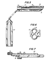
- the drill guide illustrated in Figures 5-7 comprises an elongated arm 10 having a distal end 11 which is shaped to match the profile of the spinal implant for which the apparatus is to be used.
- the drill guide has an upper surface and a lower surface and Figure 5 is a top plan view showing the upper surface a semi-cylindrical groove 12 extends from the distal end to the proximal end of each of the upper surface and the lower surface.
- Each of the grooves 12 is adapted to accommodate a drill bit (not shown) of predetermined diameter.
- the drill bit enters the groove and is rotatably held therein through a circular arch at the proximal end of the guide.
- Each groove also is adapted to accommodate a spacer comprising an elongated arm 18 ( Figure 7) having the same diameter as said drill bit of predetermined diameter.
- Both surfaces of the drill guide have equally spaced linear markings 15 which give an indication of the depth to which the guide should be inserted and are used in conjunction with the marking device described below with reference to Figures 14-16.
- the elongated arm of the drill guide is attached through an angled rigid arm 16 to a handle 17.
- the angle is such that the axis of the handle is substantially perpendicular to the axis of the elongated arm. This configuration provides satisfactory clearance for insertion of the drill bits and spacers and still allows the drill guide to be held in a stable manner during the drilling operation.
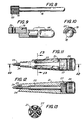
- each spacer has, at its distal end, a knurled member 19 which acts as a handle to insert and remove the spacer.
- the knurled handle includes a bore 20 through which a pin may be inserted to stabilize both spacers when in place.
- FIGs 11-13 illustrate a positioning tool which comprises an elongated member 21 having an axial bore in which is located a cylindrical member 22.
- the distal end of said cylindrical member has a thread 23 which is adapted to be screwed into a threaded hole 28 (see Figure 4) in a spinal implant.
- the proximal end of the cylindrical member is attached to a knurled knob 24 for turning said cylindrical member to screw or unscrew said threaded distal end.
- a cylindrical locking key 25 extends from the distal end of the elongated member adjacent and parallel to the threaded distal end of the axial cylindrical member. This locking key is adapted to slide into a locking hole 29 ( Figure 4) in a spinal implant. This prevents rotation of the implant about the axis of the positioning tool.
- the distal end 26 of the elongated member is shaped to match the curved profile of the spinal implant for which it is to be used.
- the cylindrical member 22 is adapted to be removed from the elongated member and is held in place therein by a spring-loaded ball bearing 27 which seats into a cooperating groove running around the internal periphery of the elongated member as shown in Figure 12.
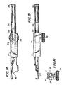
- the measuring device used in the apparatus of the invention operates as a simple caliper device which measures the depth of the vertebrae.
- the measuring device comprises a calibrated arm 30 which slides within an outer sleeve 31.
- the sleeve has an aperture 32 through which depth calibration lines 33 may be viewed.
- the distal end 34 of the calibrated arm Prior to drilling, in order to determine the correct depth for drilling the distal end 34 of the calibrated arm is placed between the vertebrae and its position is adjusted by appropriate sliding movement through a handle 35 at the proximal end.
- the calibrated arm is locked within the sleeve by screwing the knurled knob 36 of a locking screw.
- the correct depth is shown by the calibration line in the aperture 32 and this reading is matched with a corresponding reading in the markings 15 on the drill guide. Thereby the correct depth for drilling is obtained.
- the disc In order to replace a degenerate disc, the disc is first removed by a known surgical technique, leaving a space between the adjacent upper and lower vertebrae.
- the space is maintained, i.e. the vertebrae are prevented from collapsing, before and after drilling by a standard laminar spreader.
- each drill guide is calibrated accordingly. Then a drill guide is inserted to the correct depth on one side of the vertebrae after removal of the laminar spreader. Grooves in the upper and lower vertebrae are then drilled using a drill bit of the appropriate predetermined diameter. Said diameter matches the diameter of the protuberance of the correct implant for the replaced disc.
- each drill bit is removed and replaced by a spacer to maintain the spaces between the vertebrae.
- Each drill guide and attached spacers is then sequentially removed and replaced by a laminar spreader to prevent collapse of the vertebrae and, at the same time, leaving clearance for insertion of the two implants.
- the implants are inserted sequentially with the aid of the appropriate positioning tool and when each implant is properly in place between the vertebrae the positioning tool is unscrewed therefrom by turning the knurled knob and removed. When the implant is inserted the laminar spreader may be removed.
- the placement of the implants is as shown in Figure 4.
Abstract
Description
- This invention relates to a spinal implant, particularly an implant adapted to encourage bone ingrowth resulting in stabilization of adjacent vertebrae and reduction of back pain. The invention is also concerned with a method of implantation and an apparatus for placement of the spinal implant between adjacent vertebrae.
- Many types of intervertebral implants are known in the art. For example, United States Patent No. 3,867,728 discloses a prosthesis for spinal repair which comprises a laminated core element made from an elastomer, such as silicone rubber or polyurethane, and fabric-reinforced elastomer.
- United States Patent No. 4,309,777 discloses an artificial intervertebral disc comprising upper and lower disc portions having a plurality of springs positioned therebetween and spikes extending outwardly from said disc portions for engagement with adjacent upper and lower vertebrae.
- United States Patent No. 4,349,921 discloses an intervertebral disc prosthesis comprising a shaped body of substantially rigid, non-porous, biologically compatible material. The surfaces of the disc have characteristics to produce a "friction-fit".
- United States Patent No. 4,479,491 discloses an intervertebral stabilization implant including an elongated central portion and a pair of reverse wings each disposed at an angle with respect to the elongated central portion.
- Other types of spinal stabilizers, for example fixator plates and rods, are also known in the art, but these are not intervertebral implants as that term is used herein.
- It has now been found that improved stabilization is achieved by an implant which is adapted to encourage bone ingrowth and thereby stabilizes adjacent vertebrae by fusing said vertebrae to the implant.
- In accordance with the present invention there is provided a spinal implant comprising a rigid solid body having a first surface, a second surface and a third surface of predetermined thickness between and perpendicular to said first and second surfaces, each of said first and second surfaces being defined by a substantially D-shaped profile the curved portion of which conforms to the outer profile of the vertebrae between which the implant is adapted to be implanted, said predetermined thickness being chosen to correspond to the space between said vertebrae, each of said first and second surfaces having an elongated protuberance of substantially semi-circular cross-section extending the full width of the surface parallel to the straight side of the D, and at least a portion of each first and second surface having a porous coating thereon.
- Preferably, said porous coating is applied to each of said protuberances.
- In a preferred embodiment of the invention a threaded hole and an adjacent locking hole are located in said third surface parallel to the straight side of the D, for holding said implant and placing it in position between vertebrae.
- The rigid solid body of the implant according to the invention preferably is made from a high strength, biocompatible, corrosion-resistant, cobalt-chromium- molybdenum alloy and the porous coating comprises two layers of substantially spherical particles of the same or similar alloy as the body. A particularly suitable alloy of this type is that known by the registered Trade Mark "Vitallium".
- The invention also provides a method of placing a spinal implant as described above between adjacent upper and lower vertebrae in a spinal column, which comprises removing the disc between said vertebrae, measuring the resulting space between said vertebrae, placing in said space a drill guide having dimensions matching said space, drilling semi-cylindrical grooves in the upper and lower vertebrae, which grooves are positioned by use of said guide to match with complimentary protuberances in the implant, removing said drill guide and inserting a spinal implant of predetermined thickness which matches said space by locating the protuberances on the implant in the pre-drilled grooves in the upper and lower vertebrae.
- In the performance of said method, preferably the integrity of the space to receive the implant is maintained by appropriate spacers prior to insertion of the implant.
- The invention further provides a method of replacing a degenerate disc between adjacent upper and lower vertebrae in a spinal column, which comprises inserting two spinal implants in side by side relationship in the space formed by removal of said disc according to the method described above.
- The invention still further provides an apparatus for placement of a spinal implant between adjacent upper and lower vertebrae in a spinal column, which comprises:-
- (a) a drill guide comprising an elongated arm with a distal end, a proximal end, an upper surface and a lower surface, said proximal end being attached to a handle, semi-cylindrical grooves extending from said distal end to said proximal end in both the upper surface and the lower surface, each of said grooves being adapted to accommodate a drill bit of predetermined diameter;
- (b) at least one drill bit of predetermined diameter;
- (c) a measuring device associated with or incorporated in said drill guide comprising a linear gauge adapted to measure the depth of the drill bore in the vertebrae and stop means for preventing further drilling when the desired depth is achieved;
- (d) two spacers, each comprising an elongated arm having the same diameter as said drill bit of predetermined diameter, said arm being attached at its proximal end to a handle;
- (e) a positioning tool comprising an elongated member with a distal end, a proximal end and an axial bore throughout its length, a cylindrical member with a distal end and a proximal end located in said axial bore, the distal end of said cylindrical member being threaded and being adapted to be screwed into a threaded hole located in a spinal implant, the proximal end of said cylindrical member being attached to a knurled knob for turning said cylindrical member to screw or unscrew said threaded distal end and a cylindrical locking key extending from the distal end of said elongated member adjacent and parallel to said threaded axial cylindrical member, which locking key is adapted to slide into a locking hole in a spinal implant. Preferably, the distal end of said elongated member is shaped to match the profile of a spinal implant for which it is to be used.
- The invention will be more particularly described with reference to a preferred embodiment as illustrated in the accompanying drawings, in which:
- Figure 1 is a perspective view of a spinal implant according to the invention;
- Figure 2 is an end elevation of the implant of Figure 1;
- Figure 3 is a side elevation of the implant of Figure 1;
- Figure 4 is a perspective view showing two implants of the invention in place between two adjacent vertebrae;
- Figure 5 is a top view of a drill guide for an apparatus according to the invention;
- Figure 6 is an end view of said drill guide;
- Figure 7 is a side view of said drill guide;
- Figure 8 is a side view of a spacer for an apparatus according to the invention;
- Figure 9 is a detail of the proximal end of said spacer of Figure 8;
- Figure 10 is an end view of said spacer;
- figure 11 is a top view of a positional tool for an apparatus according to the invention;
- Figure 12 is a side view of said positioning tool;
- Figure 13 is a section through line 13-13 of Figure 11; and
- Figures 14-16 illustrate a measuring device used in the apparatus of the invention.
- Referring to the drawings, Figures 1-3 illustrate a preferred spinal implant according to the invention. Said implant comprises a rigid solid body having a first surface 1 and a second surface 2. A
third surface 3 of predetermined thickness is between and perpendicular to said first and second surfaces. Each of said first and second surfaces is defined by a substantially D-shaped profile whosecurved portion 4 conforms to the outer profile of the vertebrae between which the implant is adapted to be implanted (see Figure 4). The pre determined thickness of thethird surface 3 is chosen to correspond to the space between the vertebrae in which the implant is to be implanted, said thickness corresponding substantially to that of the healthy disc which originally occupied said space. When a disc between adjacent vertebrae is removed prior to placement of an implant according to the invention, the resultant space between the vertebrae is carefully measured and an implant of appropriate thickness is chosen for the subsequent implantation. - Each of the first and second surfaces 1, 2 of the implant has an
elongated protuberance 5 of substantially semi-circular cross-section extending the full width of said surface parallel to thestraight side 6 of the D. - In the preferred embodiment illustrated in Figures 1-3 the surface of each of said
protuberances 5 has aporous coating 7 thereon. - The rigid solid body of the preferred embodiment, i.e. the body defined by the above described surfaces, is made from a high strength, biocompatible, corrosion-resistant cobalt-chromium-molybdenum alloy, for example "Vitallium", and said porous coating preferably comprises two layers of substantially spherical particles of the same or similar alloy as the body. A particularly suitable porous coating is that disclosed in commonly assigned U.S.Patent No. 4,550,448, the disclosure of which is incorporated herein by reference.
- In alternative embodiments of the invention, the porous coating may extend over all or part of the first and second surfaces 1, 2 in addition to the surface of the protuberances. However, it has been found that a porous coating over the protuberances only (as illustrated in the drawings) is normally sufficient to provide adequate bone ingrowth to stabilize the vertebrae. The
third surface 3 does not come into direct contact with bone and is not porous coated. - A prime object of the porous coated spinal implant of the invention is to eliminate back pain associated with loss of joint space secondary to a back fusion procedure. The implant is designed to stabilize the vertebrae following debridement of a disc. After placement of the implant between adjacent vertebrae tissue/bone ingrowth into the porous coating provides long-term stability. The various thicknesses of the implants are chosen to reconstitute the disc space between the vertebrae, thus preventing pressure from developing about the dura and/or nerve roots relative to the collapse of said disc space.
- The protuberances, which extend anterior to posterior, provide rotational stability. This is clearly illustrated in Figure 4 which shows two implants placed in side by side relationship in the space formed by removal of a disc between two
adjacent vertebrae - Figures 5-16 of the drawings illustrate components of the preferred apparatus used for placement of the spinal implant of the invention.
- The apparatus comprises a drill guide, illustrated in Figures 5-7; spacers, illustrated in Figures 7-10; a positioning tool, illustrated in Figures 11-13 and a measuring device illustrated in Figures 14-16.
- The drill guide illustrated in Figures 5-7 comprises an
elongated arm 10 having adistal end 11 which is shaped to match the profile of the spinal implant for which the apparatus is to be used. The drill guide has an upper surface and a lower surface and Figure 5 is a top plan view showing the upper surface asemi-cylindrical groove 12 extends from the distal end to the proximal end of each of the upper surface and the lower surface. Each of thegrooves 12 is adapted to accommodate a drill bit (not shown) of predetermined diameter. - The drill bit enters the groove and is rotatably held therein through a circular arch at the proximal end of the guide. Each groove also is adapted to accommodate a spacer comprising an elongated arm 18 (Figure 7) having the same diameter as said drill bit of predetermined diameter.
- Both surfaces of the drill guide have equally spaced
linear markings 15 which give an indication of the depth to which the guide should be inserted and are used in conjunction with the marking device described below with reference to Figures 14-16. - The elongated arm of the drill guide is attached through an angled
rigid arm 16 to ahandle 17. The angle is such that the axis of the handle is substantially perpendicular to the axis of the elongated arm. This configuration provides satisfactory clearance for insertion of the drill bits and spacers and still allows the drill guide to be held in a stable manner during the drilling operation. - As shown in Figures 8-10 the
elongated arm 18 of each spacer has, at its distal end, aknurled member 19 which acts as a handle to insert and remove the spacer. The knurled handle includes abore 20 through which a pin may be inserted to stabilize both spacers when in place. - Figures 11-13 illustrate a positioning tool which comprises an
elongated member 21 having an axial bore in which is located acylindrical member 22. The distal end of said cylindrical member has athread 23 which is adapted to be screwed into a threaded hole 28 (see Figure 4) in a spinal implant. The proximal end of the cylindrical member is attached to aknurled knob 24 for turning said cylindrical member to screw or unscrew said threaded distal end. A cylindrical lockingkey 25 extends from the distal end of the elongated member adjacent and parallel to the threaded distal end of the axial cylindrical member. This locking key is adapted to slide into a locking hole 29 (Figure 4) in a spinal implant. This prevents rotation of the implant about the axis of the positioning tool. - Preferably the
distal end 26 of the elongated member is shaped to match the curved profile of the spinal implant for which it is to be used. - The
cylindrical member 22 is adapted to be removed from the elongated member and is held in place therein by a spring-loadedball bearing 27 which seats into a cooperating groove running around the internal periphery of the elongated member as shown in Figure 12. - The measuring device used in the apparatus of the invention operates as a simple caliper device which measures the depth of the vertebrae.
- As shown in Figures 14-16, the measuring device comprises a calibrated
arm 30 which slides within anouter sleeve 31. The sleeve has anaperture 32 through whichdepth calibration lines 33 may be viewed. - Prior to drilling, in order to determine the correct depth for drilling the
distal end 34 of the calibrated arm is placed between the vertebrae and its position is adjusted by appropriate sliding movement through ahandle 35 at the proximal end. When the depth of the vertebra is determined the calibrated arm is locked within the sleeve by screwing theknurled knob 36 of a locking screw. The correct depth is shown by the calibration line in theaperture 32 and this reading is matched with a corresponding reading in themarkings 15 on the drill guide. Thereby the correct depth for drilling is obtained. - In order to replace a degenerate disc, the disc is first removed by a known surgical technique, leaving a space between the adjacent upper and lower vertebrae. The space is maintained, i.e. the vertebrae are prevented from collapsing, before and after drilling by a standard laminar spreader.
- To prepare the space for insertion of side-by-side implants according to the invention appropriate grooves must be drilled in the upper and lower vertebrae.
- First and correct depth is determined with the measuring device described above and each drill guide is calibrated accordingly. Then a drill guide is inserted to the correct depth on one side of the vertebrae after removal of the laminar spreader. Grooves in the upper and lower vertebrae are then drilled using a drill bit of the appropriate predetermined diameter. Said diameter matches the diameter of the protuberance of the correct implant for the replaced disc.
- When the grooves are drilled each drill bit is removed and replaced by a spacer to maintain the spaces between the vertebrae.
- This operation is repeated on the other side of the vertebrae.
- Each drill guide and attached spacers is then sequentially removed and replaced by a laminar spreader to prevent collapse of the vertebrae and, at the same time, leaving clearance for insertion of the two implants.
- The implants are inserted sequentially with the aid of the appropriate positioning tool and when each implant is properly in place between the vertebrae the positioning tool is unscrewed therefrom by turning the knurled knob and removed. When the implant is inserted the laminar spreader may be removed. The placement of the implants is as shown in Figure 4.
Claims (9)
Priority Applications (1)
| Application Number | Priority Date | Filing Date | Title |
|---|---|---|---|
| AT88301585T ATE69370T1 (en) | 1987-02-26 | 1988-02-24 | SPINE IMPLANT. |
Applications Claiming Priority (2)
| Application Number | Priority Date | Filing Date | Title |
|---|---|---|---|
| US07/019,283 US4714469A (en) | 1987-02-26 | 1987-02-26 | Spinal implant |
| US19283 | 1987-02-26 |
Related Child Applications (1)
| Application Number | Title | Priority Date | Filing Date |
|---|---|---|---|
| EP90121104.5 Division-Into | 1988-02-24 |
Publications (3)
| Publication Number | Publication Date |
|---|---|
| EP0284210A2 true EP0284210A2 (en) | 1988-09-28 |
| EP0284210A3 EP0284210A3 (en) | 1988-12-21 |
| EP0284210B1 EP0284210B1 (en) | 1991-11-13 |
Family
ID=21792384
Family Applications (2)
| Application Number | Title | Priority Date | Filing Date |
|---|---|---|---|
| EP88301585A Expired - Lifetime EP0284210B1 (en) | 1987-02-26 | 1988-02-24 | Spinal implant |
| EP90121104A Ceased EP0421485A1 (en) | 1987-02-26 | 1988-02-24 | Apparatus for placement of a spinal implant |
Family Applications After (1)
| Application Number | Title | Priority Date | Filing Date |
|---|---|---|---|
| EP90121104A Ceased EP0421485A1 (en) | 1987-02-26 | 1988-02-24 | Apparatus for placement of a spinal implant |
Country Status (11)
| Country | Link |
|---|---|
| US (1) | US4714469A (en) |
| EP (2) | EP0284210B1 (en) |
| JP (1) | JPS63229046A (en) |
| AT (1) | ATE69370T1 (en) |
| AU (1) | AU588724B2 (en) |
| CA (2) | CA1254352A (en) |
| DE (3) | DE8806725U1 (en) |
| ES (1) | ES2027759T3 (en) |
| GR (1) | GR3003127T3 (en) |
| IE (2) | IE880284L (en) |
| ZA (1) | ZA881331B (en) |
Cited By (4)
| Publication number | Priority date | Publication date | Assignee | Title |
|---|---|---|---|---|
| EP0421485A1 (en) | 1987-02-26 | 1991-04-10 | Pfizer Hospital Products Group, Inc. | Apparatus for placement of a spinal implant |
| EP0460447A1 (en) * | 1990-06-06 | 1991-12-11 | Synthes AG, Chur | Compression drill guide |
| EP0495488A2 (en) * | 1991-01-15 | 1992-07-22 | Pfizer Hospital Products Group, Inc. | Surgical drill guide |
| US6520996B1 (en) | 1999-06-04 | 2003-02-18 | Depuy Acromed, Incorporated | Orthopedic implant |
Families Citing this family (445)
| Publication number | Priority date | Publication date | Assignee | Title |
|---|---|---|---|---|
| US4834757A (en) * | 1987-01-22 | 1989-05-30 | Brantigan John W | Prosthetic implant |
| CH672588A5 (en) * | 1987-07-09 | 1989-12-15 | Sulzer Ag | |
| CH672589A5 (en) * | 1987-07-09 | 1989-12-15 | Sulzer Ag | |
| GB8718627D0 (en) * | 1987-08-06 | 1987-09-09 | Showell A W Sugicraft Ltd | Spinal implants |
| DE3733924C2 (en) * | 1987-10-07 | 1997-06-19 | Gotzen Leo Prof Dr | Spine fixation device |
| DE3809793A1 (en) * | 1988-03-23 | 1989-10-05 | Link Waldemar Gmbh Co | SURGICAL INSTRUMENT SET |
| US5772661A (en) | 1988-06-13 | 1998-06-30 | Michelson; Gary Karlin | Methods and instrumentation for the surgical correction of human thoracic and lumbar spinal disease from the antero-lateral aspect of the spine |
| US6923810B1 (en) | 1988-06-13 | 2005-08-02 | Gary Karlin Michelson | Frusto-conical interbody spinal fusion implants |
| US7452359B1 (en) * | 1988-06-13 | 2008-11-18 | Warsaw Orthopedic, Inc. | Apparatus for inserting spinal implants |
| US5015247A (en) * | 1988-06-13 | 1991-05-14 | Michelson Gary K | Threaded spinal implant |
| US5484437A (en) | 1988-06-13 | 1996-01-16 | Michelson; Gary K. | Apparatus and method of inserting spinal implants |
| AU7139994A (en) | 1988-06-13 | 1995-01-03 | Karlin Technology, Inc. | Apparatus and method of inserting spinal implants |
| US7534254B1 (en) | 1988-06-13 | 2009-05-19 | Warsaw Orthopedic, Inc. | Threaded frusto-conical interbody spinal fusion implants |
| US7491205B1 (en) | 1988-06-13 | 2009-02-17 | Warsaw Orthopedic, Inc. | Instrumentation for the surgical correction of human thoracic and lumbar spinal disease from the lateral aspect of the spine |
| US6770074B2 (en) | 1988-06-13 | 2004-08-03 | Gary Karlin Michelson | Apparatus for use in inserting spinal implants |
| US6210412B1 (en) | 1988-06-13 | 2001-04-03 | Gary Karlin Michelson | Method for inserting frusto-conical interbody spinal fusion implants |
| US6120502A (en) | 1988-06-13 | 2000-09-19 | Michelson; Gary Karlin | Apparatus and method for the delivery of electrical current for interbody spinal arthrodesis |
| US6123705A (en) | 1988-06-13 | 2000-09-26 | Sdgi Holdings, Inc. | Interbody spinal fusion implants |
| US5609635A (en) | 1988-06-28 | 1997-03-11 | Michelson; Gary K. | Lordotic interbody spinal fusion implants |
| CA1333209C (en) * | 1988-06-28 | 1994-11-29 | Gary Karlin Michelson | Artificial spinal fusion implants |
| USD425989S (en) * | 1996-07-15 | 2000-05-30 | Sofamor Danek Holdings, Inc. | Artificial spinal fusion implant |
| CA1318469C (en) * | 1989-02-15 | 1993-06-01 | Acromed Corporation | Artificial disc |
| US5015255A (en) * | 1989-05-10 | 1991-05-14 | Spine-Tech, Inc. | Spinal stabilization method |
| CA2007210C (en) * | 1989-05-10 | 1996-07-09 | Stephen D. Kuslich | Intervertebral reamer |
| US5895427A (en) * | 1989-07-06 | 1999-04-20 | Sulzer Spine-Tech Inc. | Method for spinal fixation |
| US5458638A (en) * | 1989-07-06 | 1995-10-17 | Spine-Tech, Inc. | Non-threaded spinal implant |
| US5047055A (en) * | 1990-12-21 | 1991-09-10 | Pfizer Hospital Products Group, Inc. | Hydrogel intervertebral disc nucleus |
| US5192327A (en) * | 1991-03-22 | 1993-03-09 | Brantigan John W | Surgical prosthetic implant for vertebrae |
| US5306307A (en) * | 1991-07-22 | 1994-04-26 | Calcitek, Inc. | Spinal disk implant |
| US5320644A (en) * | 1991-08-30 | 1994-06-14 | Sulzer Brothers Limited | Intervertebral disk prosthesis |
| US5425773A (en) * | 1992-01-06 | 1995-06-20 | Danek Medical, Inc. | Intervertebral disk arthroplasty device |
| US5258031A (en) | 1992-01-06 | 1993-11-02 | Danek Medical | Intervertebral disk arthroplasty |
| US5306309A (en) * | 1992-05-04 | 1994-04-26 | Calcitek, Inc. | Spinal disk implant and implantation kit |
| US5545226A (en) * | 1992-05-29 | 1996-08-13 | Porex Technologies Corp. | Implants for cranioplasty |
| US5368593A (en) * | 1992-07-07 | 1994-11-29 | Stark; John G. | Devices and methods for attachment of spine fixation devices |
| FR2694882B1 (en) * | 1992-08-24 | 1994-10-21 | Sofamor | Intervertebral disc prosthesis. |
| ES2141217T3 (en) * | 1993-02-10 | 2000-03-16 | Sulzer Spine Tech Inc | SURGICAL TOOL SET FOR STABILIZATION OF THE SPINE. |
| US5534028A (en) * | 1993-04-20 | 1996-07-09 | Howmedica, Inc. | Hydrogel intervertebral disc nucleus with diminished lateral bulging |
| EP1508307A1 (en) | 1993-06-10 | 2005-02-23 | Karlin Technology, Inc. | Bone cutting device |
| US5431658A (en) * | 1994-02-14 | 1995-07-11 | Moskovich; Ronald | Facilitator for vertebrae grafts and prostheses |
| US5697977A (en) * | 1994-03-18 | 1997-12-16 | Pisharodi; Madhavan | Method and apparatus for spondylolisthesis reduction |
| US6093207A (en) * | 1994-03-18 | 2000-07-25 | Pisharodi; Madhavan | Middle expanded, removable intervertebral disk stabilizer disk |
| CA2551185C (en) | 1994-03-28 | 2007-10-30 | Sdgi Holdings, Inc. | Apparatus and method for anterior spinal stabilization |
| EP0752830B1 (en) * | 1994-03-28 | 2002-06-19 | MICHELSON, Gary Karlin | Apparatus for spinal fixation |
| DE69522060T2 (en) * | 1994-09-08 | 2002-05-29 | Stryker Technologies Corp | Intervertebral disc core made of hydrogel |
| US5885299A (en) * | 1994-09-15 | 1999-03-23 | Surgical Dynamics, Inc. | Apparatus and method for implant insertion |
| DE69526094T2 (en) | 1994-09-15 | 2002-11-21 | Surgical Dynamics Inc | CONICAL FUSION CAGE |
| US5674296A (en) | 1994-11-14 | 1997-10-07 | Spinal Dynamics Corporation | Human spinal disc prosthesis |
| CN1134810A (en) | 1995-02-17 | 1996-11-06 | 索发默达纳集团股份有限公司 | Improved interbody spinal fusion implants |
| US6758849B1 (en) | 1995-02-17 | 2004-07-06 | Sdgi Holdings, Inc. | Interbody spinal fusion implants |
| US5860973A (en) * | 1995-02-27 | 1999-01-19 | Michelson; Gary Karlin | Translateral spinal implant |
| US5782919A (en) * | 1995-03-27 | 1998-07-21 | Sdgi Holdings, Inc. | Interbody fusion device and method for restoration of normal spinal anatomy |
| ATE286696T1 (en) | 1995-03-27 | 2005-01-15 | Sdgi Holdings Inc | SPINAL FUSION IMPLANT AND INSERTION AND VERIFICATION TOOLS |
| US6245072B1 (en) | 1995-03-27 | 2001-06-12 | Sdgi Holdings, Inc. | Methods and instruments for interbody fusion |
| US6206922B1 (en) | 1995-03-27 | 2001-03-27 | Sdgi Holdings, Inc. | Methods and instruments for interbody fusion |
| US5702449A (en) * | 1995-06-07 | 1997-12-30 | Danek Medical, Inc. | Reinforced porous spinal implants |
| US6039762A (en) * | 1995-06-07 | 2000-03-21 | Sdgi Holdings, Inc. | Reinforced bone graft substitutes |
| DE29512362U1 (en) * | 1995-08-01 | 1995-10-12 | Gaedigk Heinz Juergen | Parallel drilling aid |
| US5782830A (en) * | 1995-10-16 | 1998-07-21 | Sdgi Holdings, Inc. | Implant insertion device |
| US6423095B1 (en) * | 1995-10-16 | 2002-07-23 | Sdgi Holdings, Inc. | Intervertebral spacers |
| US5989289A (en) | 1995-10-16 | 1999-11-23 | Sdgi Holdings, Inc. | Bone grafts |
| US5769781A (en) * | 1995-11-13 | 1998-06-23 | Chappuis; James L. | Protector retractor |
| FR2742652B1 (en) * | 1995-12-21 | 1998-02-27 | Colorado | INTERVERTEBRAL IMPLANT, INTERSOMATIC CAGE TYPE |
| US5814084A (en) * | 1996-01-16 | 1998-09-29 | University Of Florida Tissue Bank, Inc. | Diaphysial cortical dowel |
| US5865845A (en) * | 1996-03-05 | 1999-02-02 | Thalgott; John S. | Prosthetic intervertebral disc |
| US5700264A (en) * | 1996-07-01 | 1997-12-23 | Zucherman; James F. | Apparatus and method for preparing a site for an interbody fusion implant |
| FR2753368B1 (en) * | 1996-09-13 | 1999-01-08 | Chauvin Jean Luc | EXPANSIONAL OSTEOSYNTHESIS CAGE |
| AU732421B2 (en) | 1996-10-23 | 2001-04-26 | Warsaw Orthopedic, Inc. | Spinal spacer |
| US5895428A (en) * | 1996-11-01 | 1999-04-20 | Berry; Don | Load bearing spinal joint implant |
| US5961554A (en) * | 1996-12-31 | 1999-10-05 | Janson; Frank S | Intervertebral spacer |
| US7201751B2 (en) | 1997-01-02 | 2007-04-10 | St. Francis Medical Technologies, Inc. | Supplemental spine fixation device |
| US6695842B2 (en) | 1997-10-27 | 2004-02-24 | St. Francis Medical Technologies, Inc. | Interspinous process distraction system and method with positionable wing and method |
| US6156038A (en) * | 1997-01-02 | 2000-12-05 | St. Francis Medical Technologies, Inc. | Spine distraction implant and method |
| US6451019B1 (en) | 1998-10-20 | 2002-09-17 | St. Francis Medical Technologies, Inc. | Supplemental spine fixation device and method |
| US6902566B2 (en) * | 1997-01-02 | 2005-06-07 | St. Francis Medical Technologies, Inc. | Spinal implants, insertion instruments, and methods of use |
| US7306628B2 (en) | 2002-10-29 | 2007-12-11 | St. Francis Medical Technologies | Interspinous process apparatus and method with a selectably expandable spacer |
| US5860977A (en) * | 1997-01-02 | 1999-01-19 | Saint Francis Medical Technologies, Llc | Spine distraction implant and method |
| US6514256B2 (en) | 1997-01-02 | 2003-02-04 | St. Francis Medical Technologies, Inc. | Spine distraction implant and method |
| US7101375B2 (en) * | 1997-01-02 | 2006-09-05 | St. Francis Medical Technologies, Inc. | Spine distraction implant |
| US7959652B2 (en) | 2005-04-18 | 2011-06-14 | Kyphon Sarl | Interspinous process implant having deployable wings and method of implantation |
| US6068630A (en) | 1997-01-02 | 2000-05-30 | St. Francis Medical Technologies, Inc. | Spine distraction implant |
| US6712819B2 (en) * | 1998-10-20 | 2004-03-30 | St. Francis Medical Technologies, Inc. | Mating insertion instruments for spinal implants and methods of use |
| US5836948A (en) * | 1997-01-02 | 1998-11-17 | Saint Francis Medical Technologies, Llc | Spine distraction implant and method |
| US6033438A (en) * | 1997-06-03 | 2000-03-07 | Sdgi Holdings, Inc. | Open intervertebral spacer |
| GB9713330D0 (en) * | 1997-06-25 | 1997-08-27 | Bridport Gundry Plc | Surgical implant |
| EP1762202B1 (en) * | 1997-08-27 | 2011-01-05 | RTI Biologics, Inc. | Cortical bone cervical Smith-Robinson fusion implant |
| US5824094A (en) | 1997-10-17 | 1998-10-20 | Acromed Corporation | Spinal disc |
| JP4158339B2 (en) | 1997-10-27 | 2008-10-01 | メドトロニック スパイン エルエルシー | Spinal distraction implant |
| US6139579A (en) | 1997-10-31 | 2000-10-31 | Depuy Motech Acromed, Inc. | Spinal disc |
| US5888226A (en) * | 1997-11-12 | 1999-03-30 | Rogozinski; Chaim | Intervertebral prosthetic disc |
| US5932552A (en) | 1997-11-26 | 1999-08-03 | Keraplast Technologies Ltd. | Keratin-based hydrogel for biomedical applications and method of production |
| US6482233B1 (en) | 1998-01-29 | 2002-11-19 | Synthes(U.S.A.) | Prosthetic interbody spacer |
| US6679915B1 (en) * | 1998-04-23 | 2004-01-20 | Sdgi Holdings, Inc. | Articulating spinal implant |
| WO1999053871A1 (en) | 1998-04-23 | 1999-10-28 | Cauthen Research Group, Inc. | Articulating spinal implant |
| US6019792A (en) * | 1998-04-23 | 2000-02-01 | Cauthen Research Group, Inc. | Articulating spinal implant |
| US6241769B1 (en) | 1998-05-06 | 2001-06-05 | Cortek, Inc. | Implant for spinal fusion |
| US6296664B1 (en) | 1998-06-17 | 2001-10-02 | Surgical Dynamics, Inc. | Artificial intervertebral disc |
| CA2338379A1 (en) | 1998-07-22 | 2000-02-03 | Spinal Dynamics Corporation | Threaded cylindrical multidiscoid single or multiple array disc prosthesis |
| FR2782632B1 (en) | 1998-08-28 | 2000-12-29 | Materiel Orthopedique En Abreg | EXPANSIBLE INTERSOMATIC FUSION CAGE |
| US6749635B1 (en) | 1998-09-04 | 2004-06-15 | Sdgi Holdings, Inc. | Peanut spectacle multi discoid thoraco-lumbar disc prosthesis |
| US6652534B2 (en) | 1998-10-20 | 2003-11-25 | St. Francis Medical Technologies, Inc. | Apparatus and method for determining implant size |
| US6652527B2 (en) | 1998-10-20 | 2003-11-25 | St. Francis Medical Technologies, Inc. | Supplemental spine fixation device and method |
| US7029473B2 (en) | 1998-10-20 | 2006-04-18 | St. Francis Medical Technologies, Inc. | Deflectable spacer for use as an interspinous process implant and method |
| US7189234B2 (en) | 1998-10-20 | 2007-03-13 | St. Francis Medical Technologies, Inc. | Interspinous process implant sizer and distractor with a split head and size indicator and method |
| US6174311B1 (en) | 1998-10-28 | 2001-01-16 | Sdgi Holdings, Inc. | Interbody fusion grafts and instrumentation |
| DE60038160T2 (en) * | 1999-01-11 | 2009-03-12 | SDGI Holdings, Inc., Wilmington | COOLED, OPEN INTERMEDIATE DISTANCE PIECE |
| US6547823B2 (en) * | 1999-01-22 | 2003-04-15 | Osteotech, Inc. | Intervertebral implant |
| US6746485B1 (en) | 1999-02-18 | 2004-06-08 | St. Francis Medical Technologies, Inc. | Hair used as a biologic disk, replacement, and/or structure and method |
| US6113638A (en) | 1999-02-26 | 2000-09-05 | Williams; Lytton A. | Method and apparatus for intervertebral implant anchorage |
| US6241770B1 (en) * | 1999-03-05 | 2001-06-05 | Gary K. Michelson | Interbody spinal fusion implant having an anatomically conformed trailing end |
| CA2594492A1 (en) | 1999-03-07 | 2000-09-14 | Active Implants Corporation | Method and apparatus for computerized surgery |
| US6442814B1 (en) | 1999-04-23 | 2002-09-03 | Spinal Concepts, Inc. | Apparatus for manufacturing a bone dowel |
| US6557226B1 (en) | 1999-04-23 | 2003-05-06 | Michael E. Landry | Apparatus for manufacturing a bone dowel |
| WO2000064359A1 (en) * | 1999-04-28 | 2000-11-02 | Harrington James Frederick Jr | Modular anterior cervical plate |
| AU4988700A (en) * | 1999-05-05 | 2000-11-17 | Gary K. Michelson | Spinal fusion implants with opposed locking screws |
| JP4221159B2 (en) * | 1999-05-05 | 2009-02-12 | ウォーソー・オーソペディック・インコーポレーテッド | Nested interbody spinal fusion implant |
| US6419704B1 (en) | 1999-10-08 | 2002-07-16 | Bret Ferree | Artificial intervertebral disc replacement methods and apparatus |
| US6969404B2 (en) * | 1999-10-08 | 2005-11-29 | Ferree Bret A | Annulus fibrosis augmentation methods and apparatus |
| US6277149B1 (en) | 1999-06-08 | 2001-08-21 | Osteotech, Inc. | Ramp-shaped intervertebral implant |
| DE59914691D1 (en) | 1999-07-02 | 2008-04-24 | Spine Solutions Inc | INTERVERTEBRAL IMPLANT |
| US6159212A (en) * | 1999-08-02 | 2000-12-12 | Schoedinger, Iii; George R. | Surgical tool and method to reduce vertebral displacement |
| FR2897259B1 (en) | 2006-02-15 | 2008-05-09 | Ldr Medical Soc Par Actions Si | INTERSOMATIC TRANSFORAMINAL CAGE WITH INTERBREBAL FUSION GRAFT AND CAGE IMPLANTATION INSTRUMENT |
| US6685695B2 (en) * | 1999-08-13 | 2004-02-03 | Bret A. Ferree | Method and apparatus for providing nutrition to intervertebral disc tissue |
| US6793677B2 (en) * | 1999-08-13 | 2004-09-21 | Bret A. Ferree | Method of providing cells and other biologic materials for transplantation |
| US7435260B2 (en) | 1999-08-13 | 2008-10-14 | Ferree Bret A | Use of morphogenetic proteins to treat human disc disease |
| US6454804B1 (en) | 1999-10-08 | 2002-09-24 | Bret A. Ferree | Engineered tissue annulus fibrosis augmentation methods and apparatus |
| US7201776B2 (en) * | 1999-10-08 | 2007-04-10 | Ferree Bret A | Artificial intervertebral disc replacements with endplates |
| US6755863B2 (en) * | 1999-10-08 | 2004-06-29 | Bret A. Ferree | Rotator cuff repair using engineered tissues |
| EP1328221B1 (en) | 1999-08-18 | 2009-03-25 | Intrinsic Therapeutics, Inc. | Devices for nucleus pulposus augmentation and retention |
| US7553329B2 (en) | 1999-08-18 | 2009-06-30 | Intrinsic Therapeutics, Inc. | Stabilized intervertebral disc barrier |
| FR2798059B1 (en) * | 1999-09-08 | 2002-03-22 | Phusis | INTERSOMATIC IMPLANT, DEVICE FOR STABILIZATION OF THE RACHIS AND KIT FOR THE PRODUCTION OF AN ARTHRODESIS |
| US6783546B2 (en) | 1999-09-13 | 2004-08-31 | Keraplast Technologies, Ltd. | Implantable prosthetic or tissue expanding device |
| US6371984B1 (en) | 1999-09-13 | 2002-04-16 | Keraplast Technologies, Ltd. | Implantable prosthetic or tissue expanding device |
| EP1212015B1 (en) | 1999-09-14 | 2007-02-21 | Spine Solutions Inc. | Instrument for inserting intervertebral implants |
| US6264695B1 (en) * | 1999-09-30 | 2001-07-24 | Replication Medical, Inc. | Spinal nucleus implant |
| US6645247B2 (en) * | 1999-10-08 | 2003-11-11 | Bret A. Ferree | Supplementing engineered annulus tissues with autograft of allograft tendons |
| US20040172019A1 (en) * | 1999-10-08 | 2004-09-02 | Ferree Bret A. | Reinforcers for artificial disc replacement methods and apparatus |
| US7201774B2 (en) * | 1999-10-08 | 2007-04-10 | Ferree Bret A | Artificial intervertebral disc replacements incorporating reinforced wall sections |
| US6648920B2 (en) * | 1999-10-08 | 2003-11-18 | Bret A. Ferree | Natural and synthetic supplements to engineered annulus and disc tissues |
| US20030026788A1 (en) * | 1999-10-08 | 2003-02-06 | Ferree Bret A. | Use of extracellular matrix tissue to preserve cultured cell phenotype |
| US7060100B2 (en) * | 1999-10-08 | 2006-06-13 | Ferree Bret A | Artificial disc and joint replacements with modular cushioning components |
| US6648919B2 (en) * | 1999-10-14 | 2003-11-18 | Bret A. Ferree | Transplantation of engineered meniscus tissue to the intervertebral disc |
| US6524318B1 (en) * | 1999-10-18 | 2003-02-25 | Sulzer Spine-Tech Inc. | Spinal surgery instruments and methods |
| WO2001028469A2 (en) * | 1999-10-21 | 2001-04-26 | Sdgi Holdings, Inc. | Devices and techniques for a posterior lateral disc space approach |
| US6764491B2 (en) | 1999-10-21 | 2004-07-20 | Sdgi Holdings, Inc. | Devices and techniques for a posterior lateral disc space approach |
| US6830570B1 (en) | 1999-10-21 | 2004-12-14 | Sdgi Holdings, Inc. | Devices and techniques for a posterior lateral disc space approach |
| US6491695B1 (en) | 1999-11-05 | 2002-12-10 | Carl Roggenbuck | Apparatus and method for aligning vertebrae |
| US6319257B1 (en) | 1999-12-20 | 2001-11-20 | Kinamed, Inc. | Inserter assembly |
| US20010032017A1 (en) | 1999-12-30 | 2001-10-18 | Alfaro Arthur A. | Intervertebral implants |
| US6447512B1 (en) | 2000-01-06 | 2002-09-10 | Spinal Concepts, Inc. | Instrument and method for implanting an interbody fusion device |
| DE10003967A1 (en) * | 2000-01-25 | 2001-08-09 | Biomet Merck Deutschland Gmbh | Guide device |
| US6709458B2 (en) | 2000-02-04 | 2004-03-23 | Gary Karlin Michelson | Expandable push-in arcuate interbody spinal fusion implant with tapered configuration during insertion |
| US6716247B2 (en) | 2000-02-04 | 2004-04-06 | Gary K. Michelson | Expandable push-in interbody spinal fusion implant |
| EP1645248B8 (en) * | 2000-02-04 | 2010-06-16 | Warsaw Orthopedic, Inc. | Expandable interbody spinal fusion implant having pivotally attached blocker |
| US6500205B1 (en) * | 2000-04-19 | 2002-12-31 | Gary K. Michelson | Expandable threaded arcuate interbody spinal fusion implant with cylindrical configuration during insertion |
| US6814756B1 (en) | 2000-02-04 | 2004-11-09 | Gary K. Michelson | Expandable threaded arcuate interbody spinal fusion implant with lordotic configuration during insertion |
| DE60133370T2 (en) * | 2000-02-22 | 2009-04-02 | Warsaw Orthopedic, Inc., Warsaw | SPINE IMPLANT AND INTRODUCTION DEVICE |
| US6740093B2 (en) | 2000-02-28 | 2004-05-25 | Stephen Hochschuler | Method and apparatus for treating a vertebral body |
| WO2001080784A1 (en) * | 2000-04-19 | 2001-11-01 | Michelson Gary K | Hemi-lumbar interbody spinal implant having an asymmetrical leading end and method for installation thereof |
| US6350283B1 (en) | 2000-04-19 | 2002-02-26 | Gary K. Michelson | Bone hemi-lumbar interbody spinal implant having an asymmetrical leading end and method of installation thereof |
| US7462195B1 (en) | 2000-04-19 | 2008-12-09 | Warsaw Orthopedic, Inc. | Artificial lumbar interbody spinal implant having an asymmetrical leading end |
| US6342057B1 (en) | 2000-04-28 | 2002-01-29 | Synthes (Usa) | Remotely aligned surgical drill guide |
| US6379364B1 (en) | 2000-04-28 | 2002-04-30 | Synthes (Usa) | Dual drill guide for a locking bone plate |
| FR2808995B1 (en) | 2000-05-18 | 2003-02-21 | Aesculap Sa | INTERSOMATIC CAGE WITH UNIFIED GRAFT |
| JP2003534849A (en) | 2000-05-30 | 2003-11-25 | リン,ポール・エス | Implant placed between cervical vertebrae |
| USD501555S1 (en) | 2000-06-12 | 2005-02-01 | Ortho Development Corporation | Implant |
| US6579318B2 (en) * | 2000-06-12 | 2003-06-17 | Ortho Development Corporation | Intervertebral spacer |
| WO2001095837A1 (en) * | 2000-06-13 | 2001-12-20 | Michelson Gary K | Manufactured major long bone ring implant shaped to conform to a prepared intervertebral implantation space |
| US20020111680A1 (en) * | 2000-06-13 | 2002-08-15 | Michelson Gary K. | Ratcheted bone dowel |
| US6808537B2 (en) * | 2000-07-07 | 2004-10-26 | Gary Karlin Michelson | Expandable implant with interlocking walls |
| US7125380B2 (en) | 2000-08-08 | 2006-10-24 | Warsaw Orthopedic, Inc. | Clamping apparatus and methods |
| WO2002011633A2 (en) | 2000-08-08 | 2002-02-14 | Sdgi Holdings, Inc. | Improved method and apparatus for stereotactic implantation |
| US7601174B2 (en) | 2000-08-08 | 2009-10-13 | Warsaw Orthopedic, Inc. | Wear-resistant endoprosthetic devices |
| AU2001281166B2 (en) | 2000-08-08 | 2006-07-20 | Warsaw Orthopedic, Inc. | Implantable joint prosthesis |
| US7226480B2 (en) * | 2000-08-15 | 2007-06-05 | Depuy Spine, Inc. | Disc prosthesis |
| US6458159B1 (en) * | 2000-08-15 | 2002-10-01 | John S. Thalgott | Disc prosthesis |
| US6824565B2 (en) * | 2000-09-08 | 2004-11-30 | Nabil L. Muhanna | System and methods for inserting a vertebral spacer |
| US8628575B2 (en) | 2000-08-29 | 2014-01-14 | Nabil L. Muhanna | Vertebral body replacement and method of use |
| US6506213B1 (en) * | 2000-09-08 | 2003-01-14 | Ferro Corporation | Manufacturing orthopedic parts using supercritical fluid processing techniques |
| US6572654B1 (en) | 2000-10-04 | 2003-06-03 | Albert N. Santilli | Intervertebral spacer |
| US6743256B2 (en) * | 2000-10-11 | 2004-06-01 | Michael D. Mason | Graftless spinal fusion device |
| US20030120274A1 (en) | 2000-10-20 | 2003-06-26 | Morris John W. | Implant retaining device |
| CA2422884C (en) * | 2000-10-24 | 2009-05-19 | Cryolife, Inc. | In situ bioprosthetic filler and methods, particularly for the in situ formation of vertebral disc bioprosthetics |
| WO2002085284A2 (en) * | 2000-11-07 | 2002-10-31 | Cryolife, Inc. | Expandable foam-like biomaterials and methods |
| ATE282379T1 (en) | 2001-02-04 | 2004-12-15 | Michelson Gary K | INSTRUMENT FOR INSERTING AND EXPANDING AN INTERVERBAL FUSION IMPLANT |
| US6562045B2 (en) | 2001-02-13 | 2003-05-13 | Sdgi Holdings, Inc. | Machining apparatus |
| WO2002065954A1 (en) | 2001-02-16 | 2002-08-29 | Queen's University At Kingston | Method and device for treating scoliosis |
| US6673075B2 (en) | 2001-02-23 | 2004-01-06 | Albert N. Santilli | Porous intervertebral spacer |
| DE60138521D1 (en) * | 2001-02-27 | 2009-06-10 | Co Ligne Ag | Medical implant |
| US6478822B1 (en) * | 2001-03-20 | 2002-11-12 | Spineco, Inc. | Spherical spinal implant |
| US6899734B2 (en) | 2001-03-23 | 2005-05-31 | Howmedica Osteonics Corp. | Modular implant for fusing adjacent bone structure |
| US6368351B1 (en) | 2001-03-27 | 2002-04-09 | Bradley J. Glenn | Intervertebral space implant for use in spinal fusion procedures |
| US6989031B2 (en) | 2001-04-02 | 2006-01-24 | Sdgi Holdings, Inc. | Hemi-interbody spinal implant manufactured from a major long bone ring or a bone composite |
| US6890355B2 (en) | 2001-04-02 | 2005-05-10 | Gary K. Michelson | Artificial contoured spinal fusion implants made of a material other than bone |
| US6749636B2 (en) | 2001-04-02 | 2004-06-15 | Gary K. Michelson | Contoured spinal fusion implants made of bone or a bone composite material |
| US6582433B2 (en) | 2001-04-09 | 2003-06-24 | St. Francis Medical Technologies, Inc. | Spine fixation device and method |
| FR2824261B1 (en) | 2001-05-04 | 2004-05-28 | Ldr Medical | INTERVERTEBRAL DISC PROSTHESIS AND IMPLEMENTATION METHOD AND TOOLS |
| US7156877B2 (en) * | 2001-06-29 | 2007-01-02 | The Regents Of The University Of California | Biodegradable/bioactive nucleus pulposus implant and method for treating degenerated intervertebral discs |
| US20090234457A1 (en) * | 2001-06-29 | 2009-09-17 | The Regents Of The University Of California | Systems, devices and methods for treatment of intervertebral disorders |
| FR2827156B1 (en) | 2001-07-13 | 2003-11-14 | Ldr Medical | VERTEBRAL CAGE DEVICE WITH MODULAR FASTENING |
| US6926728B2 (en) * | 2001-07-18 | 2005-08-09 | St. Francis Medical Technologies, Inc. | Curved dilator and method |
| JP4744023B2 (en) * | 2001-07-24 | 2011-08-10 | 日本電産サーボ株式会社 | Permanent magnet 3-phase stepping motor |
| US7018412B2 (en) | 2001-08-20 | 2006-03-28 | Ebi, L.P. | Allograft spinal implant |
| US6783721B2 (en) | 2001-10-30 | 2004-08-31 | Howmedica Osteonics Corp. | Method of making an ion treated hydrogel |
| US7285121B2 (en) | 2001-11-05 | 2007-10-23 | Warsaw Orthopedic, Inc. | Devices and methods for the correction and treatment of spinal deformities |
| US7025787B2 (en) | 2001-11-26 | 2006-04-11 | Sdgi Holdings, Inc. | Implantable joint prosthesis and associated instrumentation |
| US6855167B2 (en) | 2001-12-05 | 2005-02-15 | Osteotech, Inc. | Spinal intervertebral implant, interconnections for such implant and processes for making |
| US7708776B1 (en) | 2002-01-16 | 2010-05-04 | Nuvasive, Inc. | Intervertebral disk replacement system and methods |
| AR038680A1 (en) | 2002-02-19 | 2005-01-26 | Synthes Ag | INTERVERTEBRAL IMPLANT |
| US7637952B2 (en) * | 2002-03-11 | 2009-12-29 | Zimmer Spine, Inc. | Instrumentation and procedure for implanting spinal implant devices |
| WO2003084449A1 (en) | 2002-03-30 | 2003-10-16 | Cool Brace | Intervertebral device and method of use |
| US6689132B2 (en) | 2002-05-15 | 2004-02-10 | Spineco, Inc. | Spinal implant insertion tool |
| US8388684B2 (en) | 2002-05-23 | 2013-03-05 | Pioneer Signal Technology, Inc. | Artificial disc device |
| US7001433B2 (en) | 2002-05-23 | 2006-02-21 | Pioneer Laboratories, Inc. | Artificial intervertebral disc device |
| US7049348B2 (en) * | 2002-07-06 | 2006-05-23 | Kensey Nash Corporation | Resorbable structure for treating and healing of tissue defects |
| ATE462383T1 (en) | 2002-09-24 | 2010-04-15 | Bogomir Gorensek | STABILIZING DEVICE FOR INTERVERBAL DISCS AND METHOD THEREOF |
| WO2004034982A2 (en) * | 2002-10-15 | 2004-04-29 | Medtronic Inc. | Treatment termination in a medical device |
| US8048117B2 (en) | 2003-05-22 | 2011-11-01 | Kyphon Sarl | Interspinous process implant and method of implantation |
| US7273496B2 (en) | 2002-10-29 | 2007-09-25 | St. Francis Medical Technologies, Inc. | Artificial vertebral disk replacement implant with crossbar spacer and method |
| US7749252B2 (en) | 2005-03-21 | 2010-07-06 | Kyphon Sarl | Interspinous process implant having deployable wing and method of implantation |
| US7497859B2 (en) * | 2002-10-29 | 2009-03-03 | Kyphon Sarl | Tools for implanting an artificial vertebral disk |
| US7833246B2 (en) | 2002-10-29 | 2010-11-16 | Kyphon SÀRL | Interspinous process and sacrum implant and method |
| US7083649B2 (en) | 2002-10-29 | 2006-08-01 | St. Francis Medical Technologies, Inc. | Artificial vertebral disk replacement implant with translating pivot point |
| US7909853B2 (en) | 2004-09-23 | 2011-03-22 | Kyphon Sarl | Interspinous process implant including a binder and method of implantation |
| US7549999B2 (en) | 2003-05-22 | 2009-06-23 | Kyphon Sarl | Interspinous process distraction implant and method of implantation |
| US8070778B2 (en) | 2003-05-22 | 2011-12-06 | Kyphon Sarl | Interspinous process implant with slide-in distraction piece and method of implantation |
| US6966929B2 (en) | 2002-10-29 | 2005-11-22 | St. Francis Medical Technologies, Inc. | Artificial vertebral disk replacement implant with a spacer |
| FR2846550B1 (en) | 2002-11-05 | 2006-01-13 | Ldr Medical | INTERVERTEBRAL DISC PROSTHESIS |
| US7204852B2 (en) | 2002-12-13 | 2007-04-17 | Spine Solutions, Inc. | Intervertebral implant, insertion tool and method of inserting same |
| EP2335656B1 (en) | 2003-02-06 | 2012-09-05 | Synthes GmbH | Implant between vertebrae |
| US7335203B2 (en) * | 2003-02-12 | 2008-02-26 | Kyphon Inc. | System and method for immobilizing adjacent spinous processes |
| KR20050107426A (en) | 2003-02-14 | 2005-11-11 | 디퍼이 스파인 인코포레이티드 | In-situ formed intervertebral fusion device and method |
| US7824444B2 (en) * | 2003-03-20 | 2010-11-02 | Spineco, Inc. | Expandable spherical spinal implant |
| US7918876B2 (en) | 2003-03-24 | 2011-04-05 | Theken Spine, Llc | Spinal implant adjustment device |
| EP1610740A4 (en) | 2003-04-04 | 2009-04-08 | Theken Disc Llc | Artificial disc prosthesis |
| US7491204B2 (en) | 2003-04-28 | 2009-02-17 | Spine Solutions, Inc. | Instruments and method for preparing an intervertebral space for receiving an artificial disc implant |
| US7520947B2 (en) * | 2003-05-23 | 2009-04-21 | Ati Properties, Inc. | Cobalt alloys, methods of making cobalt alloys, and implants and articles of manufacture made therefrom |
| US20040267367A1 (en) | 2003-06-30 | 2004-12-30 | Depuy Acromed, Inc | Intervertebral implant with conformable endplate |
| US7803162B2 (en) | 2003-07-21 | 2010-09-28 | Spine Solutions, Inc. | Instruments and method for inserting an intervertebral implant |
| US9254137B2 (en) * | 2003-08-29 | 2016-02-09 | Lanterna Medical Technologies Ltd | Facet implant |
| US20050055099A1 (en) * | 2003-09-09 | 2005-03-10 | Ku David N. | Flexible spinal disc |
| US7794465B2 (en) * | 2003-09-10 | 2010-09-14 | Warsaw Orthopedic, Inc. | Artificial spinal discs and associated implantation instruments and methods |
| US7766914B2 (en) * | 2003-09-10 | 2010-08-03 | Warsaw Orthopedic, Inc. | Adjustable drill guide |
| US8372152B2 (en) | 2003-09-30 | 2013-02-12 | X-Spine Systems, Inc. | Spinal fusion system utilizing an implant plate having at least one integral lock and ratchet lock |
| US7182782B2 (en) | 2003-09-30 | 2007-02-27 | X-Spine Systems, Inc. | Spinal fusion system and method for fusing spinal bones |
| US8821553B2 (en) | 2003-09-30 | 2014-09-02 | X-Spine Systems, Inc. | Spinal fusion system utilizing an implant plate having at least one integral lock |
| US8062367B2 (en) | 2003-09-30 | 2011-11-22 | X-Spine Systems, Inc. | Screw locking mechanism and method |
| US7641701B2 (en) | 2003-09-30 | 2010-01-05 | X-Spine Systems, Inc. | Spinal fusion system and method for fusing spinal bones |
| US9078706B2 (en) | 2003-09-30 | 2015-07-14 | X-Spine Systems, Inc. | Intervertebral fusion device utilizing multiple mobile uniaxial and bidirectional screw interface plates |
| US7131974B2 (en) * | 2003-10-14 | 2006-11-07 | Keyer Thomas R | Surgical drill guide |
| US9445916B2 (en) * | 2003-10-22 | 2016-09-20 | Pioneer Surgical Technology, Inc. | Joint arthroplasty devices having articulating members |
| US7520899B2 (en) | 2003-11-05 | 2009-04-21 | Kyphon Sarl | Laterally insertable artificial vertebral disk replacement implant with crossbar spacer |
| US7837732B2 (en) | 2003-11-20 | 2010-11-23 | Warsaw Orthopedic, Inc. | Intervertebral body fusion cage with keels and implantation methods |
| US7691146B2 (en) | 2003-11-21 | 2010-04-06 | Kyphon Sarl | Method of laterally inserting an artificial vertebral disk replacement implant with curved spacer |
| US20050209603A1 (en) | 2003-12-02 | 2005-09-22 | St. Francis Medical Technologies, Inc. | Method for remediation of intervertebral disks |
| US20050154462A1 (en) | 2003-12-02 | 2005-07-14 | St. Francis Medical Technologies, Inc. | Laterally insertable artificial vertebral disk replacement implant with translating pivot point |
| US20050159746A1 (en) * | 2004-01-21 | 2005-07-21 | Dieter Grob | Cervical facet resurfacing implant |
| AU2005209304B2 (en) | 2004-01-27 | 2010-08-26 | Warsaw Orthopedic, Inc. | Stabilized bone graft |
| US20050171550A1 (en) * | 2004-01-30 | 2005-08-04 | Sdgi Holdings, Inc. | Anatomic implants designed to minimize instruments and surgical techniques |
| FR2865629B1 (en) | 2004-02-04 | 2007-01-26 | Ldr Medical | INTERVERTEBRAL DISC PROSTHESIS |
| RU2354334C2 (en) | 2004-02-04 | 2009-05-10 | Лдр Медикаль | Intervertebral disc prosthesis |
| US7846183B2 (en) | 2004-02-06 | 2010-12-07 | Spinal Elements, Inc. | Vertebral facet joint prosthesis and method of fixation |
| US7195644B2 (en) | 2004-03-02 | 2007-03-27 | Joint Synergy, Llc | Ball and dual socket joint |
| US7083651B2 (en) * | 2004-03-03 | 2006-08-01 | Joint Synergy, Llc | Spinal implant |
| US7115144B2 (en) | 2004-03-02 | 2006-10-03 | Joint Synergy, Llc | Spinal implant |
| US7491239B2 (en) | 2005-02-23 | 2009-02-17 | Joint Synergy, Llc | Interior insert ball and dual socket joint |
| US8636802B2 (en) | 2004-03-06 | 2014-01-28 | DePuy Synthes Products, LLC | Dynamized interspinal implant |
| ATE506919T1 (en) * | 2004-03-26 | 2011-05-15 | Nuvasive Inc | DISC PROSTHESIS |
| US20080306595A1 (en) * | 2004-03-26 | 2008-12-11 | Pearsalls Limited | Porous Implant For Spinal Disc Nucleus Replacement |
| US7282165B2 (en) * | 2004-04-27 | 2007-10-16 | Howmedica Osteonics Corp. | Wear resistant hydrogel for bearing applications |
| FR2869528B1 (en) | 2004-04-28 | 2007-02-02 | Ldr Medical | INTERVERTEBRAL DISC PROSTHESIS |
| US7524324B2 (en) | 2004-04-28 | 2009-04-28 | Kyphon Sarl | System and method for an interspinous process implant as a supplement to a spine stabilization implant |
| US7544208B1 (en) | 2004-05-03 | 2009-06-09 | Theken Spine, Llc | Adjustable corpectomy apparatus |
| WO2005112833A1 (en) * | 2004-05-20 | 2005-12-01 | Pearsalls Limited | Improvements in and relating to surgical implants |
| US9504583B2 (en) | 2004-06-10 | 2016-11-29 | Spinal Elements, Inc. | Implant and method for facet immobilization |
| US8172904B2 (en) | 2004-06-30 | 2012-05-08 | Synergy Disc Replacement, Inc. | Artificial spinal disc |
| WO2006004848A1 (en) | 2004-06-30 | 2006-01-12 | Synergy Disc Replacement, Inc. | Artificial spinal disc |
| US9237958B2 (en) | 2004-06-30 | 2016-01-19 | Synergy Disc Replacement Inc. | Joint prostheses |
| ES2331007T3 (en) * | 2004-09-08 | 2009-12-18 | Synthes Gmbh | UNIVERSAL APPLICATION INTERVERTEBRAL DISK PROTESIS. |
| US8012209B2 (en) | 2004-09-23 | 2011-09-06 | Kyphon Sarl | Interspinous process implant including a binder, binder aligner and method of implantation |
| US7575600B2 (en) | 2004-09-29 | 2009-08-18 | Kyphon Sarl | Artificial vertebral disk replacement implant with translating articulation contact surface and method |
| US7481840B2 (en) | 2004-09-29 | 2009-01-27 | Kyphon Sarl | Multi-piece artificial spinal disk replacement device with selectably positioning articulating element |
| US8721722B2 (en) | 2004-10-18 | 2014-05-13 | Ebi, Llc | Intervertebral implant and associated method |
| US8172855B2 (en) | 2004-11-24 | 2012-05-08 | Abdou M S | Devices and methods for inter-vertebral orthopedic device placement |
| US8029540B2 (en) | 2005-05-10 | 2011-10-04 | Kyphon Sarl | Inter-cervical facet implant with implantation tool |
| US20060247633A1 (en) | 2004-12-13 | 2006-11-02 | St. Francis Medical Technologies, Inc. | Inter-cervical facet implant with surface enhancements |
| US8066749B2 (en) | 2004-12-13 | 2011-11-29 | Warsaw Orthopedic, Inc. | Implant for stabilizing a bone graft during spinal fusion |
| US8100944B2 (en) | 2004-12-13 | 2012-01-24 | Kyphon Sarl | Inter-cervical facet implant and method for preserving the tissues surrounding the facet joint |
| US7776090B2 (en) | 2004-12-13 | 2010-08-17 | Warsaw Orthopedic, Inc. | Inter-cervical facet implant and method |
| US8118838B2 (en) | 2004-12-13 | 2012-02-21 | Kyphon Sarl | Inter-cervical facet implant with multiple direction articulation joint and method for implanting |
| US8128660B2 (en) | 2004-12-13 | 2012-03-06 | Kyphon Sarl | Inter-cervical facet joint implant with locking screw system |
| FR2879436B1 (en) | 2004-12-22 | 2007-03-09 | Ldr Medical | INTERVERTEBRAL DISC PROSTHESIS |
| US8083798B2 (en) * | 2005-04-04 | 2011-12-27 | Warsaw Orthopedic, Inc. | Non-circular stabilization sphere and method |
| US7799080B2 (en) * | 2005-04-22 | 2010-09-21 | Doty Keith L | Spinal disc prosthesis and methods of use |
| US7361192B2 (en) | 2005-04-22 | 2008-04-22 | Doty Keith L | Spinal disc prosthesis and methods of use |
| WO2006133130A2 (en) * | 2005-06-03 | 2006-12-14 | Nuvasive, Inc. | Fibrous spinal implant and method of implantation |
| GB0514891D0 (en) * | 2005-07-20 | 2005-08-24 | Pearsalls Ltd | Improvements in and relating to implants |
| US20120143341A1 (en) * | 2006-12-12 | 2012-06-07 | Arthrodisc, L.L.C. | Devices and methods for visual differentiation of intervertebral spaces |
| US20060282166A1 (en) * | 2005-06-09 | 2006-12-14 | Sdgi Holdings, Inc. | Compliant porous coating |
| FR2887762B1 (en) | 2005-06-29 | 2007-10-12 | Ldr Medical Soc Par Actions Si | INTERVERTEBRAL DISC PROSTHESIS INSERTION INSTRUMENTATION BETWEEN VERTEBRATES |
| US8623088B1 (en) | 2005-07-15 | 2014-01-07 | Nuvasive, Inc. | Spinal fusion implant and related methods |
| FR2891135B1 (en) | 2005-09-23 | 2008-09-12 | Ldr Medical Sarl | INTERVERTEBRAL DISC PROSTHESIS |
| US8435295B2 (en) | 2005-09-26 | 2013-05-07 | Infinity Orthopaedics Company | System and method for intervertebral implant delivery and removal |
| FR2893838B1 (en) | 2005-11-30 | 2008-08-08 | Ldr Medical Soc Par Actions Si | PROSTHESIS OF INTERVERTEBRAL DISC AND INSTRUMENTATION OF INSERTION OF THE PROSTHESIS BETWEEN VERTEBRATES |
| US7988695B2 (en) | 2005-12-21 | 2011-08-02 | Theken Spine, Llc | Articulated delivery instrument |
| US7935148B2 (en) | 2006-01-09 | 2011-05-03 | Warsaw Orthopedic, Inc. | Adjustable insertion device for a vertebral implant |
| US7662183B2 (en) * | 2006-01-24 | 2010-02-16 | Timothy Haines | Dynamic spinal implants incorporating cartilage bearing graft material |
| US20070179618A1 (en) * | 2006-01-31 | 2007-08-02 | Sdgi Holdings, Inc. | Intervertebral prosthetic disc |
| EP1988855A2 (en) | 2006-02-27 | 2008-11-12 | Synthes GmbH | Intervertebral implant with fixation geometry |
| US20070225810A1 (en) * | 2006-03-23 | 2007-09-27 | Dennis Colleran | Flexible cage spinal implant |
| US7976549B2 (en) | 2006-03-23 | 2011-07-12 | Theken Spine, Llc | Instruments for delivering spinal implants |
| US7780676B2 (en) | 2006-07-11 | 2010-08-24 | Ebi, Llc | Intervertebral implantation apparatus |
| USD741488S1 (en) | 2006-07-17 | 2015-10-20 | Nuvasive, Inc. | Spinal fusion implant |
| EP3628244A1 (en) | 2006-07-24 | 2020-04-01 | Centinel Spine Schweiz GmbH | Intervertebral implant with keel |
| EP2046211B1 (en) | 2006-07-31 | 2018-06-27 | Centinel Spine Schweiz GmbH | Drilling/milling guide and keel cut preparation system |
| US8062303B2 (en) | 2006-08-16 | 2011-11-22 | K2M, Inc. | Apparatus and methods for inserting an implant |
| US8043377B2 (en) | 2006-09-02 | 2011-10-25 | Osprey Biomedical, Inc. | Implantable intervertebral fusion device |
| US8506636B2 (en) | 2006-09-08 | 2013-08-13 | Theken Spine, Llc | Offset radius lordosis |
| US8715350B2 (en) | 2006-09-15 | 2014-05-06 | Pioneer Surgical Technology, Inc. | Systems and methods for securing an implant in intervertebral space |
| US8066750B2 (en) | 2006-10-06 | 2011-11-29 | Warsaw Orthopedic, Inc | Port structures for non-rigid bone plates |
| US20080161927A1 (en) * | 2006-10-18 | 2008-07-03 | Warsaw Orthopedic, Inc. | Intervertebral Implant with Porous Portions |
| US8105382B2 (en) | 2006-12-07 | 2012-01-31 | Interventional Spine, Inc. | Intervertebral implant |
| US8974496B2 (en) | 2007-08-30 | 2015-03-10 | Jeffrey Chun Wang | Interspinous implant, tools and methods of implanting |
| US7942104B2 (en) * | 2007-01-22 | 2011-05-17 | Nuvasive, Inc. | 3-dimensional embroidery structures via tension shaping |
| US7946236B2 (en) * | 2007-01-31 | 2011-05-24 | Nuvasive, Inc. | Using zigzags to create three-dimensional embroidered structures |
| WO2008098125A2 (en) * | 2007-02-08 | 2008-08-14 | Nuvasive, Inc. | Medical implants with pre-settled cores and related methods |
| AU2008216371B2 (en) | 2007-02-12 | 2014-04-10 | Warsaw Orthopedic, Inc. | Joint revision implant |
| US8465546B2 (en) | 2007-02-16 | 2013-06-18 | Ldr Medical | Intervertebral disc prosthesis insertion assemblies |
| EP2129304B1 (en) | 2007-02-22 | 2014-09-03 | Spinal Elements, Inc. | Vertebral articular process drill |
| US8992533B2 (en) | 2007-02-22 | 2015-03-31 | Spinal Elements, Inc. | Vertebral facet joint drill and method of use |
| US20090048675A1 (en) * | 2007-04-25 | 2009-02-19 | Bhatnagar Mohit K | Spinal Fusion Implants with Selectively Applied Bone Growth Promoting Agent |
| US8257395B2 (en) | 2007-09-21 | 2012-09-04 | Jmea Corporation | Spinal fixation with selectively applied bone growth promoting agent |
| US8241357B2 (en) * | 2007-04-25 | 2012-08-14 | Jmea Corporation | Prosthesis with a selectively applied bone growth promoting agent |
| US8480715B2 (en) | 2007-05-22 | 2013-07-09 | Zimmer Spine, Inc. | Spinal implant system and method |
| FR2916956B1 (en) | 2007-06-08 | 2012-12-14 | Ldr Medical | INTERSOMATIC CAGE, INTERVERTEBRAL PROSTHESIS, ANCHORING DEVICE AND IMPLANTATION INSTRUMENTATION |
| US7744649B2 (en) * | 2007-06-25 | 2010-06-29 | Moore Mark R | Spondylolisthesis correction apparatus and method |
| US8216313B2 (en) * | 2007-06-25 | 2012-07-10 | Moore Mark R | Spondylolisthesis correction apparatus and method |
| US8377130B2 (en) | 2010-04-30 | 2013-02-19 | Mark R. Moore | Spondylolisthesis correction apparatus and method |
| US8900307B2 (en) | 2007-06-26 | 2014-12-02 | DePuy Synthes Products, LLC | Highly lordosed fusion cage |
| US7963982B2 (en) * | 2007-07-16 | 2011-06-21 | X-Spine Systems, Inc. | Implant plate screw locking system and screw having a locking member |
| US8282681B2 (en) * | 2007-08-13 | 2012-10-09 | Nuvasive, Inc. | Bioresorbable spinal implant and related methods |
| EP2211785B1 (en) | 2007-10-25 | 2016-01-27 | Synergy Disc Replacement, Inc. | Systems for vertebral disc replacement |
| WO2009064644A1 (en) | 2007-11-16 | 2009-05-22 | Synthes(U.S.A.) | Low profile intervertebral implant |
| US20090157190A1 (en) * | 2007-12-13 | 2009-06-18 | Howmedica Inc. | Osteotomy spacer |
| EP2471493A1 (en) | 2008-01-17 | 2012-07-04 | Synthes GmbH | An expandable intervertebral implant and associated method of manufacturing the same |
| US8202299B2 (en) | 2008-03-19 | 2012-06-19 | Collabcom II, LLC | Interspinous implant, tools and methods of implanting |
| US8216317B2 (en) * | 2008-03-31 | 2012-07-10 | Stryker Spine | Spinal implant apparatus and methods |
| US8377135B1 (en) | 2008-03-31 | 2013-02-19 | Nuvasive, Inc. | Textile-based surgical implant and related methods |
| WO2009124269A1 (en) | 2008-04-05 | 2009-10-08 | Synthes Usa, Llc | Expandable intervertebral implant |
| US20090270873A1 (en) | 2008-04-24 | 2009-10-29 | Fabian Henry F | Spine surgery method and inserter |
| US8382767B2 (en) * | 2008-10-31 | 2013-02-26 | K2M, Inc. | Implant insertion tool |
| CA2742812A1 (en) | 2008-11-07 | 2010-05-14 | William P. Mcdonough | Zero-profile interbody spacer and coupled plate assembly |
| US8323292B2 (en) * | 2008-12-15 | 2012-12-04 | Spinecore, Inc. | Adjustable pin drill guide and methods therefor |
| US8216316B2 (en) | 2008-12-17 | 2012-07-10 | X-Spine Systems, Inc. | Prosthetic implant with biplanar angulation and compound angles |
| US8425603B2 (en) | 2008-12-22 | 2013-04-23 | Synthes Usa, Llc | Orthopedic implant with flexible keel |
| US8157865B2 (en) * | 2009-01-22 | 2012-04-17 | Stephen Hochschuler | Apparatus and method for stabilizing adjacent bone portions |
| EP2408381B1 (en) | 2009-03-16 | 2014-11-12 | Synthes GmbH | System for stabilizing vertebrae in spine surgery through a lateral access channel |
| US9526620B2 (en) | 2009-03-30 | 2016-12-27 | DePuy Synthes Products, Inc. | Zero profile spinal fusion cage |
| US8641766B2 (en) | 2009-04-15 | 2014-02-04 | DePuy Synthes Products, LLC | Arcuate fixation member |
| US9408715B2 (en) | 2009-04-15 | 2016-08-09 | DePuy Synthes Products, Inc. | Arcuate fixation member |
| US8226724B2 (en) | 2009-06-18 | 2012-07-24 | Doty Keith L | Intervertebral spinal disc prosthesis |
| BR112012005663A2 (en) | 2009-09-17 | 2021-07-27 | Synthes Gmbh | intervertebral implant with expandable bone fixation limbs |
| USD731063S1 (en) | 2009-10-13 | 2015-06-02 | Nuvasive, Inc. | Spinal fusion implant |
| US9028553B2 (en) | 2009-11-05 | 2015-05-12 | DePuy Synthes Products, Inc. | Self-pivoting spinal implant and associated instrumentation |
| US8764806B2 (en) | 2009-12-07 | 2014-07-01 | Samy Abdou | Devices and methods for minimally invasive spinal stabilization and instrumentation |
| US9393129B2 (en) | 2009-12-10 | 2016-07-19 | DePuy Synthes Products, Inc. | Bellows-like expandable interbody fusion cage |
| RU2573945C2 (en) | 2009-12-31 | 2016-01-27 | Лдр Медикал | Fastening device, intervertebral implant and device for implantation |
| SG182463A1 (en) | 2010-01-13 | 2012-08-30 | Jcbd Llc | Sacroiliac joint fixation fusion system |
| US9421109B2 (en) | 2010-01-13 | 2016-08-23 | Jcbd, Llc | Systems and methods of fusing a sacroiliac joint |
| WO2012174485A1 (en) | 2011-06-17 | 2012-12-20 | Jcbd, Llc | Sacroiliac joint implant system |
| US9554909B2 (en) | 2012-07-20 | 2017-01-31 | Jcbd, Llc | Orthopedic anchoring system and methods |
| US9333090B2 (en) | 2010-01-13 | 2016-05-10 | Jcbd, Llc | Systems for and methods of fusing a sacroiliac joint |
| US9381045B2 (en) | 2010-01-13 | 2016-07-05 | Jcbd, Llc | Sacroiliac joint implant and sacroiliac joint instrument for fusing a sacroiliac joint |
| US8979860B2 (en) | 2010-06-24 | 2015-03-17 | DePuy Synthes Products. LLC | Enhanced cage insertion device |
| US9282979B2 (en) | 2010-06-24 | 2016-03-15 | DePuy Synthes Products, Inc. | Instruments and methods for non-parallel disc space preparation |
| EP2588034B1 (en) | 2010-06-29 | 2018-01-03 | Synthes GmbH | Distractible intervertebral implant |
| WO2012012327A1 (en) | 2010-07-20 | 2012-01-26 | X-Spine Systems, Inc. | Composite orthopedic implant having a low friction material substrate with primary frictional features and secondary frictional features |
| US9474625B2 (en) * | 2010-09-03 | 2016-10-25 | Globus Medical, Inc | Expandable fusion device and method of installation thereof |
| US8425529B2 (en) | 2010-09-30 | 2013-04-23 | Stryker Spine | Instrument for inserting surgical implant with guiding rail |
| US8858637B2 (en) | 2010-09-30 | 2014-10-14 | Stryker Spine | Surgical implant with guiding rail |
| US8603175B2 (en) | 2010-09-30 | 2013-12-10 | Stryker Spine | Method of inserting surgical implant with guiding rail |
| US9402732B2 (en) | 2010-10-11 | 2016-08-02 | DePuy Synthes Products, Inc. | Expandable interspinous process spacer implant |
| EP2654626B1 (en) | 2010-12-21 | 2016-02-24 | Synthes GmbH | Intervertebral implants and systems |
| US8740949B2 (en) | 2011-02-24 | 2014-06-03 | Spinal Elements, Inc. | Methods and apparatus for stabilizing bone |
| US9271765B2 (en) | 2011-02-24 | 2016-03-01 | Spinal Elements, Inc. | Vertebral facet joint fusion implant and method for fusion |
| USD724733S1 (en) | 2011-02-24 | 2015-03-17 | Spinal Elements, Inc. | Interbody bone implant |
| US8540721B2 (en) | 2011-04-04 | 2013-09-24 | Amicus Design Group, Llc | Adjustable apparatus and methods for inserting an implant |
| US8277505B1 (en) | 2011-06-10 | 2012-10-02 | Doty Keith L | Devices for providing up to six-degrees of motion having kinematically-linked components and methods of use |
| US8845728B1 (en) | 2011-09-23 | 2014-09-30 | Samy Abdou | Spinal fixation devices and methods of use |
| USD739935S1 (en) | 2011-10-26 | 2015-09-29 | Spinal Elements, Inc. | Interbody bone implant |
| AT13086U1 (en) * | 2011-11-29 | 2013-05-15 | Ronald J Dr Sabitzer | IMPLANT |
| US8287598B1 (en) | 2011-12-05 | 2012-10-16 | TrueMotion Spine, Inc. | True spinal motion preserving, shock absorbing, intervertebral spinal disc prosthesis |
| US9241807B2 (en) | 2011-12-23 | 2016-01-26 | Pioneer Surgical Technology, Inc. | Systems and methods for inserting a spinal device |
| US20130226240A1 (en) | 2012-02-22 | 2013-08-29 | Samy Abdou | Spinous process fixation devices and methods of use |
| FR2987256B1 (en) | 2012-02-24 | 2014-08-08 | Ldr Medical | ANCHORING DEVICE FOR INTERVERTEBRAL IMPLANT, INTERVERTEBRAL IMPLANT AND IMPLANTATION INSTRUMENTATION |
| US8814912B2 (en) | 2012-07-27 | 2014-08-26 | Zimmer Spine, Inc. | Bone stabilization member with bone screw retention mechanism |
| US9198767B2 (en) | 2012-08-28 | 2015-12-01 | Samy Abdou | Devices and methods for spinal stabilization and instrumentation |
| US9320617B2 (en) | 2012-10-22 | 2016-04-26 | Cogent Spine, LLC | Devices and methods for spinal stabilization and instrumentation |
| US10022245B2 (en) | 2012-12-17 | 2018-07-17 | DePuy Synthes Products, Inc. | Polyaxial articulating instrument |
| US9522070B2 (en) | 2013-03-07 | 2016-12-20 | Interventional Spine, Inc. | Intervertebral implant |
| US10327910B2 (en) | 2013-03-14 | 2019-06-25 | X-Spine Systems, Inc. | Spinal implant and assembly |
| USD765853S1 (en) | 2013-03-14 | 2016-09-06 | Spinal Elements, Inc. | Flexible elongate member with a portion configured to receive a bone anchor |
| US9820784B2 (en) | 2013-03-14 | 2017-11-21 | Spinal Elements, Inc. | Apparatus for spinal fixation and methods of use |
| US9421044B2 (en) | 2013-03-14 | 2016-08-23 | Spinal Elements, Inc. | Apparatus for bone stabilization and distraction and methods of use |
| US9717539B2 (en) | 2013-07-30 | 2017-08-01 | Jcbd, Llc | Implants, systems, and methods for fusing a sacroiliac joint |
| US10245087B2 (en) | 2013-03-15 | 2019-04-02 | Jcbd, Llc | Systems and methods for fusing a sacroiliac joint and anchoring an orthopedic appliance |
| US9700356B2 (en) | 2013-07-30 | 2017-07-11 | Jcbd, Llc | Systems for and methods of fusing a sacroiliac joint |
| US9826986B2 (en) | 2013-07-30 | 2017-11-28 | Jcbd, Llc | Systems for and methods of preparing a sacroiliac joint for fusion |
| US9510872B2 (en) | 2013-03-15 | 2016-12-06 | Jcbd, Llc | Spinal stabilization system |
| US9456855B2 (en) | 2013-09-27 | 2016-10-04 | Spinal Elements, Inc. | Method of placing an implant between bone portions |
| US9839450B2 (en) | 2013-09-27 | 2017-12-12 | Spinal Elements, Inc. | Device and method for reinforcement of a facet |
| US9801546B2 (en) | 2014-05-27 | 2017-10-31 | Jcbd, Llc | Systems for and methods of diagnosing and treating a sacroiliac joint disorder |
| US9498351B2 (en) * | 2014-06-04 | 2016-11-22 | Spine Wave, Inc. | Apparatus for locating the position of a spinal implant during surgery |
| US9314348B2 (en) | 2014-06-04 | 2016-04-19 | Wenzel Spine, Inc. | Bilaterally expanding intervertebral body fusion device |
| WO2016044432A1 (en) | 2014-09-17 | 2016-03-24 | Spinal Elements, Inc. | Flexible fastening band connector |
| US9867718B2 (en) | 2014-10-22 | 2018-01-16 | DePuy Synthes Products, Inc. | Intervertebral implants, systems, and methods of use |
| WO2016122868A1 (en) | 2015-01-27 | 2016-08-04 | Spinal Elements, Inc. | Facet joint implant |
| WO2016137983A1 (en) | 2015-02-24 | 2016-09-01 | X-Spine Systems, Inc. | Modular interspinous fixation system with threaded component |
| US11426290B2 (en) | 2015-03-06 | 2022-08-30 | DePuy Synthes Products, Inc. | Expandable intervertebral implant, system, kit and method |
| US10857003B1 (en) | 2015-10-14 | 2020-12-08 | Samy Abdou | Devices and methods for vertebral stabilization |
| CN109688981A (en) | 2016-06-28 | 2019-04-26 | Eit 新兴移植技术股份有限公司 | Distensible, adjustable angle intervertebral cage |
| WO2018002715A2 (en) | 2016-06-28 | 2018-01-04 | Eit Emerging Implant Technologies Gmbh | Expandable and angularly adjustable articulating intervertebral cages |
| US10973648B1 (en) | 2016-10-25 | 2021-04-13 | Samy Abdou | Devices and methods for vertebral bone realignment |
| US10744000B1 (en) | 2016-10-25 | 2020-08-18 | Samy Abdou | Devices and methods for vertebral bone realignment |
| US10888433B2 (en) | 2016-12-14 | 2021-01-12 | DePuy Synthes Products, Inc. | Intervertebral implant inserter and related methods |
| US10398563B2 (en) | 2017-05-08 | 2019-09-03 | Medos International Sarl | Expandable cage |
| US11344424B2 (en) | 2017-06-14 | 2022-05-31 | Medos International Sarl | Expandable intervertebral implant and related methods |
| US10940016B2 (en) | 2017-07-05 | 2021-03-09 | Medos International Sarl | Expandable intervertebral fusion cage |
| US10966843B2 (en) | 2017-07-18 | 2021-04-06 | DePuy Synthes Products, Inc. | Implant inserters and related methods |
| US11045331B2 (en) | 2017-08-14 | 2021-06-29 | DePuy Synthes Products, Inc. | Intervertebral implant inserters and related methods |
| US11147682B2 (en) | 2017-09-08 | 2021-10-19 | Pioneer Surgical Technology, Inc. | Intervertebral implants, instruments, and methods |
| US10603055B2 (en) | 2017-09-15 | 2020-03-31 | Jcbd, Llc | Systems for and methods of preparing and fusing a sacroiliac joint |
| USD907771S1 (en) | 2017-10-09 | 2021-01-12 | Pioneer Surgical Technology, Inc. | Intervertebral implant |
| US11179248B2 (en) | 2018-10-02 | 2021-11-23 | Samy Abdou | Devices and methods for spinal implantation |
| US11446156B2 (en) | 2018-10-25 | 2022-09-20 | Medos International Sarl | Expandable intervertebral implant, inserter instrument, and related methods |
| US11369491B2 (en) | 2018-12-07 | 2022-06-28 | Globus Medical, Inc. | Trial inserter and trial head |
| US11219531B2 (en) | 2019-04-10 | 2022-01-11 | Wenzel Spine, Inc. | Rotatable intervertebral spacing implant |
| AU2020278453A1 (en) | 2019-05-22 | 2022-01-20 | Spinal Elements, Inc. | Bone tie and bone tie inserter |
| US11457959B2 (en) | 2019-05-22 | 2022-10-04 | Spinal Elements, Inc. | Bone tie and bone tie inserter |
| US11452618B2 (en) | 2019-09-23 | 2022-09-27 | Dimicron, Inc | Spinal artificial disc removal tool |
| US11883303B2 (en) | 2019-12-30 | 2024-01-30 | Vertebration, Inc. | Spine surgery method and instrumentation |
| WO2021163313A1 (en) | 2020-02-14 | 2021-08-19 | Spinal Elements, Inc. | Bone tie methods |
| US11426286B2 (en) | 2020-03-06 | 2022-08-30 | Eit Emerging Implant Technologies Gmbh | Expandable intervertebral implant |
| US11850160B2 (en) | 2021-03-26 | 2023-12-26 | Medos International Sarl | Expandable lordotic intervertebral fusion cage |
| US11752009B2 (en) | 2021-04-06 | 2023-09-12 | Medos International Sarl | Expandable intervertebral fusion cage |
Citations (6)
| Publication number | Priority date | Publication date | Assignee | Title |
|---|---|---|---|---|
| US3867728A (en) * | 1971-12-30 | 1975-02-25 | Cutter Lab | Prosthesis for spinal repair |
| DE2365873A1 (en) * | 1973-08-10 | 1976-08-26 | Pfaudler Werke Ag | SPINE ENDOPROSTHESIS AND MANUFACTURING METHOD |
| FR2372622A1 (en) * | 1976-12-03 | 1978-06-30 | Fassio Bernard | Intervertebral prosthesis for surgical use - has flat semicircular disc with hemispherical boss each side to support between vertebrae |
| US4501269A (en) * | 1981-12-11 | 1985-02-26 | Washington State University Research Foundation, Inc. | Process for fusing bone joints |
| US4550448A (en) * | 1982-02-18 | 1985-11-05 | Pfizer Hospital Products Group, Inc. | Bone prosthesis with porous coating |
| EP0179695A1 (en) * | 1984-09-26 | 1986-04-30 | Pierre Kehr | Vertebral prosthesis, in particular for cervical vertebrae |
Family Cites Families (16)
| Publication number | Priority date | Publication date | Assignee | Title |
|---|---|---|---|---|
| DE2263842A1 (en) * | 1972-12-28 | 1974-07-04 | Hoffmann Daimler Siegfried Dr | DISC PROTHESIS |
| CH624573A5 (en) * | 1978-02-01 | 1981-08-14 | Sulzer Ag | Intervertebral prosthesis |
| SU695664A1 (en) * | 1978-03-28 | 1979-11-05 | Киевский Научно-Исследовательский Институт Нейрохирургии | Instrument for removing discal hernia |
| CH640131A5 (en) * | 1979-10-03 | 1983-12-30 | Sulzer Ag | Complete intervertebral prosthesis |
| US4450834A (en) * | 1979-10-18 | 1984-05-29 | Ace Orthopedic Manufacturing, Inc. | External fixation device |
| DE3010421A1 (en) * | 1980-03-19 | 1981-09-24 | Waldemar Link (Gmbh & Co), 2000 Hamburg | INSTRUMENT FOR HOLDING AND INSERTING THE TIBIA PLATE FOR A KNEE-JOINT SLIDING PROSTHESIS |
| CA1146301A (en) | 1980-06-13 | 1983-05-17 | J. David Kuntz | Intervertebral disc prosthesis |
| US4309777A (en) | 1980-11-13 | 1982-01-12 | Patil Arun A | Artificial intervertebral disc |
| JPS58501160A (en) * | 1981-07-27 | 1983-07-21 | バッテル・デイベロプメント・コ−ポレ−シヨン | Prosthesis and method of forming a porous coating on its surface |
| EP0077159A1 (en) * | 1981-10-14 | 1983-04-20 | Brian Norman Atkins | Vertebrae spreader |
| SU1132930A1 (en) * | 1982-06-23 | 1985-01-07 | Sharovarin Konstantin | Apparatus for fixing bone fragments |
| US4479491A (en) | 1982-07-26 | 1984-10-30 | Martin Felix M | Intervertebral stabilization implant |
| EP0176728B1 (en) * | 1984-09-04 | 1989-07-26 | Humboldt-Universität zu Berlin | Intervertebral-disc prosthesis |
| US4608972A (en) * | 1985-02-19 | 1986-09-02 | Small Irwin A | Method of applying a chin implant, drill guide tool and implant |
| DE3620549A1 (en) * | 1986-06-19 | 1987-12-23 | S & G Implants Gmbh | IMPLANT FOR FIXING NEXT SPINE BONES OF THE SPINE |
| US4714469A (en) | 1987-02-26 | 1987-12-22 | Pfizer Hospital Products Group, Inc. | Spinal implant |
-
1987
- 1987-02-26 US US07/019,283 patent/US4714469A/en not_active Expired - Fee Related
-
1988
- 1988-02-02 IE IE880284A patent/IE880284L/en unknown
- 1988-02-20 DE DE8806725U patent/DE8806725U1/de not_active Expired
- 1988-02-20 DE DE8802202U patent/DE8802202U1/de not_active Expired
- 1988-02-22 CA CA000559425A patent/CA1254352A/en not_active Expired
- 1988-02-24 EP EP88301585A patent/EP0284210B1/en not_active Expired - Lifetime
- 1988-02-24 DE DE8888301585T patent/DE3866141D1/en not_active Expired - Fee Related
- 1988-02-24 EP EP90121104A patent/EP0421485A1/en not_active Ceased
- 1988-02-24 ES ES198888301585T patent/ES2027759T3/en not_active Expired - Lifetime
- 1988-02-24 AT AT88301585T patent/ATE69370T1/en not_active IP Right Cessation
- 1988-02-25 JP JP63040942A patent/JPS63229046A/en active Pending
- 1988-02-25 AU AU12191/88A patent/AU588724B2/en not_active Ceased
- 1988-02-25 ZA ZA881331A patent/ZA881331B/en unknown
-
1989
- 1989-03-02 CA CA000592648A patent/CA1261104A/en not_active Expired
-
1991
- 1991-07-02 IE IE912322A patent/IE912322A1/en not_active Application Discontinuation
- 1991-11-14 GR GR91401706T patent/GR3003127T3/en unknown
Patent Citations (6)
| Publication number | Priority date | Publication date | Assignee | Title |
|---|---|---|---|---|
| US3867728A (en) * | 1971-12-30 | 1975-02-25 | Cutter Lab | Prosthesis for spinal repair |
| DE2365873A1 (en) * | 1973-08-10 | 1976-08-26 | Pfaudler Werke Ag | SPINE ENDOPROSTHESIS AND MANUFACTURING METHOD |
| FR2372622A1 (en) * | 1976-12-03 | 1978-06-30 | Fassio Bernard | Intervertebral prosthesis for surgical use - has flat semicircular disc with hemispherical boss each side to support between vertebrae |
| US4501269A (en) * | 1981-12-11 | 1985-02-26 | Washington State University Research Foundation, Inc. | Process for fusing bone joints |
| US4550448A (en) * | 1982-02-18 | 1985-11-05 | Pfizer Hospital Products Group, Inc. | Bone prosthesis with porous coating |
| EP0179695A1 (en) * | 1984-09-26 | 1986-04-30 | Pierre Kehr | Vertebral prosthesis, in particular for cervical vertebrae |
Cited By (5)
| Publication number | Priority date | Publication date | Assignee | Title |
|---|---|---|---|---|
| EP0421485A1 (en) | 1987-02-26 | 1991-04-10 | Pfizer Hospital Products Group, Inc. | Apparatus for placement of a spinal implant |
| EP0460447A1 (en) * | 1990-06-06 | 1991-12-11 | Synthes AG, Chur | Compression drill guide |
| EP0495488A2 (en) * | 1991-01-15 | 1992-07-22 | Pfizer Hospital Products Group, Inc. | Surgical drill guide |
| EP0495488A3 (en) * | 1991-01-15 | 1992-10-21 | Pfizer Hospital Products Group, Inc. | Surgical drill guide |
| US6520996B1 (en) | 1999-06-04 | 2003-02-18 | Depuy Acromed, Incorporated | Orthopedic implant |
Also Published As
| Publication number | Publication date |
|---|---|
| EP0284210A3 (en) | 1988-12-21 |
| EP0284210B1 (en) | 1991-11-13 |
| US4714469A (en) | 1987-12-22 |
| DE8802202U1 (en) | 1988-09-01 |
| ATE69370T1 (en) | 1991-11-15 |
| AU588724B2 (en) | 1989-09-21 |
| IE880284L (en) | 1988-08-26 |
| ES2027759T3 (en) | 1992-06-16 |
| DE3866141D1 (en) | 1991-12-19 |
| DE8806725U1 (en) | 1988-09-01 |
| CA1261104C (en) | 1989-09-26 |
| CA1261104A (en) | 1989-09-26 |
| EP0421485A1 (en) | 1991-04-10 |
| CA1254352A (en) | 1989-05-23 |
| AU1219188A (en) | 1988-09-01 |
| GR3003127T3 (en) | 1993-02-17 |
| ZA881331B (en) | 1989-11-29 |
| IE912322A1 (en) | 1988-08-26 |
| JPS63229046A (en) | 1988-09-22 |
Similar Documents
| Publication | Publication Date | Title |
|---|---|---|
| US4714469A (en) | Spinal implant | |
| US7255703B2 (en) | Variable-axis surgical driver | |
| US8721722B2 (en) | Intervertebral implant and associated method | |
| US7241315B2 (en) | Femoral head resurfacing apparatus and methods | |
| US7051451B2 (en) | Facet joint prosthesis measurement and implant tools | |
| AU770606B2 (en) | Method and device for fixing and correcting spondylolisthesis anteriorly | |
| EP0807426B1 (en) | Acetabular trial | |
| EP0832622B1 (en) | A spinal cage assembly | |
| US5860969A (en) | Version adjustment instrument for modular femoral components and method of using same | |
| US7794503B2 (en) | Trialing system and method for modular hip joint replacement system | |
| US4878915A (en) | Surgical prosthetic implant facilitating vertebral interbody fusion | |
| US5554191A (en) | Intersomatic vertebral cage | |
| US6277123B1 (en) | Prosthesis positioning apparatus and method for implanting a prosthesis | |
| US8206399B2 (en) | Artificial intervertebral joint permitting translational and rotational motion | |
| EP1912578B1 (en) | Total disc replacement system | |
| US20060085077A1 (en) | Intervertebral implant and associated method | |
| US20010007957A1 (en) | Method and apparatus for segmental bone replacement | |
| EP0428303A1 (en) | Modular hip joint prosthesis with adjustable anteversion | |
| EP1459712A2 (en) | Artificial intervertebral joint permitting translational and rotational motion | |
| US20070282444A1 (en) | Kit of spine gauge blocks and a tool assembly | |
| US20120259365A1 (en) | Facet fusion implant, instrumentation, and surgical procedure | |
| US20030018391A1 (en) | Total hip joint replacement prosthesis |
Legal Events
| Date | Code | Title | Description |
|---|---|---|---|
| PUAI | Public reference made under article 153(3) epc to a published international application that has entered the european phase |
Free format text: ORIGINAL CODE: 0009012 |
|
| 17P | Request for examination filed |
Effective date: 19880806 |
|
| AK | Designated contracting states |
Kind code of ref document: A2 Designated state(s): AT BE CH DE ES FR GB GR IT LI LU NL SE |
|
| PUAL | Search report despatched |
Free format text: ORIGINAL CODE: 0009013 |
|
| AK | Designated contracting states |
Kind code of ref document: A3 Designated state(s): AT BE CH DE ES FR GB GR IT LI LU NL SE |
|
| 17Q | First examination report despatched |
Effective date: 19900718 |
|
| GRAA | (expected) grant |
Free format text: ORIGINAL CODE: 0009210 |
|
| AK | Designated contracting states |
Kind code of ref document: B1 Designated state(s): AT BE CH DE ES FR GB GR IT LI LU NL SE |
|
| PGFP | Annual fee paid to national office [announced via postgrant information from national office to epo] |
Ref country code: LU Payment date: 19911113 Year of fee payment: 5 |
|
| REF | Corresponds to: |
Ref document number: 69370 Country of ref document: AT Date of ref document: 19911115 Kind code of ref document: T |
|
| XX | Miscellaneous (additional remarks) |
Free format text: TEILANMELDUNG 90121104.5 EINGEREICHT AM 24/02/88. |
|
| PGFP | Annual fee paid to national office [announced via postgrant information from national office to epo] |
Ref country code: GR Payment date: 19911114 Year of fee payment: 5 |
|
| PGFP | Annual fee paid to national office [announced via postgrant information from national office to epo] |
Ref country code: GB Payment date: 19911126 Year of fee payment: 5 |
|
| REF | Corresponds to: |
Ref document number: 3866141 Country of ref document: DE Date of ref document: 19911219 |
|
| PGFP | Annual fee paid to national office [announced via postgrant information from national office to epo] |
Ref country code: AT Payment date: 19911230 Year of fee payment: 5 |
|
| PGFP | Annual fee paid to national office [announced via postgrant information from national office to epo] |
Ref country code: CH Payment date: 19920107 Year of fee payment: 5 |
|
| ITF | It: translation for a ep patent filed |
Owner name: MODIANO & ASSOCIATI S.R.L. |
|
| ET | Fr: translation filed | ||
| PGFP | Annual fee paid to national office [announced via postgrant information from national office to epo] |
Ref country code: ES Payment date: 19920214 Year of fee payment: 5 |
|
| PGFP | Annual fee paid to national office [announced via postgrant information from national office to epo] |
Ref country code: DE Payment date: 19920228 Year of fee payment: 5 |
|
| PGFP | Annual fee paid to national office [announced via postgrant information from national office to epo] |
Ref country code: BE Payment date: 19920312 Year of fee payment: 5 |
|
| EPTA | Lu: last paid annual fee | ||
| REG | Reference to a national code |
Ref country code: ES Ref legal event code: FG2A Ref document number: 2027759 Country of ref document: ES Kind code of ref document: T3 |
|
| PLBE | No opposition filed within time limit |
Free format text: ORIGINAL CODE: 0009261 |
|
| STAA | Information on the status of an ep patent application or granted ep patent |
Free format text: STATUS: NO OPPOSITION FILED WITHIN TIME LIMIT |
|
| REG | Reference to a national code |
Ref country code: GR Ref legal event code: FG4A Free format text: 3003127 |
|
| 26N | No opposition filed | ||
| PGFP | Annual fee paid to national office [announced via postgrant information from national office to epo] |
Ref country code: FR Payment date: 19921228 Year of fee payment: 6 |
|
| PGFP | Annual fee paid to national office [announced via postgrant information from national office to epo] |
Ref country code: SE Payment date: 19930125 Year of fee payment: 6 |
|
| PG25 | Lapsed in a contracting state [announced via postgrant information from national office to epo] |
Ref country code: LU Free format text: LAPSE BECAUSE OF NON-PAYMENT OF DUE FEES Effective date: 19930224 Ref country code: GB Effective date: 19930224 Ref country code: AT Effective date: 19930224 |
|
| PG25 | Lapsed in a contracting state [announced via postgrant information from national office to epo] |
Ref country code: ES Free format text: LAPSE BECAUSE OF NON-PAYMENT OF DUE FEES Effective date: 19930225 |
|
| REG | Reference to a national code |
Ref country code: CH Ref legal event code: PFA Free format text: HOWMEDICA, INC. |
|
| PG25 | Lapsed in a contracting state [announced via postgrant information from national office to epo] |
Ref country code: LI Effective date: 19930228 Ref country code: CH Effective date: 19930228 Ref country code: BE Effective date: 19930228 |
|
| PGFP | Annual fee paid to national office [announced via postgrant information from national office to epo] |
Ref country code: NL Payment date: 19930228 Year of fee payment: 6 |
|
| BERE | Be: lapsed |
Owner name: PFIZER HOSPITAL PRODUCTS GROUP INC. Effective date: 19930228 |
|
| PG25 | Lapsed in a contracting state [announced via postgrant information from national office to epo] |
Ref country code: GR Free format text: THE PATENT HAS BEEN ANNULLED BY A DECISION OF A NATIONAL AUTHORITY Effective date: 19930831 |
|
| GBPC | Gb: european patent ceased through non-payment of renewal fee |
Effective date: 19930224 |
|
| REG | Reference to a national code |
Ref country code: CH Ref legal event code: PL |
|
| PG25 | Lapsed in a contracting state [announced via postgrant information from national office to epo] |
Ref country code: DE Effective date: 19931103 |
|
| PG25 | Lapsed in a contracting state [announced via postgrant information from national office to epo] |
Ref country code: SE Effective date: 19940225 |
|
| PG25 | Lapsed in a contracting state [announced via postgrant information from national office to epo] |
Ref country code: NL Effective date: 19940901 |
|
| NLV4 | Nl: lapsed or anulled due to non-payment of the annual fee | ||
| PG25 | Lapsed in a contracting state [announced via postgrant information from national office to epo] |
Ref country code: FR Effective date: 19941031 |
|
| REG | Reference to a national code |
Ref country code: FR Ref legal event code: ST Ref country code: GR Ref legal event code: MM2A Free format text: 3003127 |
|
| EUG | Se: european patent has lapsed |
Ref document number: 88301585.1 Effective date: 19940910 |
|
| REG | Reference to a national code |
Ref country code: ES Ref legal event code: FD2A Effective date: 19990405 |
|
| PG25 | Lapsed in a contracting state [announced via postgrant information from national office to epo] |
Ref country code: IT Free format text: LAPSE BECAUSE OF NON-PAYMENT OF DUE FEES;WARNING: LAPSES OF ITALIAN PATENTS WITH EFFECTIVE DATE BEFORE 2007 MAY HAVE OCCURRED AT ANY TIME BEFORE 2007. THE CORRECT EFFECTIVE DATE MAY BE DIFFERENT FROM THE ONE RECORDED. Effective date: 20050224 |