EP0284177A1 - Method and apparatus for spot weld control - Google Patents
Method and apparatus for spot weld control Download PDFInfo
- Publication number
- EP0284177A1 EP0284177A1 EP88300482A EP88300482A EP0284177A1 EP 0284177 A1 EP0284177 A1 EP 0284177A1 EP 88300482 A EP88300482 A EP 88300482A EP 88300482 A EP88300482 A EP 88300482A EP 0284177 A1 EP0284177 A1 EP 0284177A1
- Authority
- EP
- European Patent Office
- Prior art keywords
- weld
- rate
- current
- transit time
- change
- Prior art date
- Legal status (The legal status is an assumption and is not a legal conclusion. Google has not performed a legal analysis and makes no representation as to the accuracy of the status listed.)
- Granted
Links
- 238000000034 method Methods 0.000 title claims description 19
- 238000012544 monitoring process Methods 0.000 claims description 10
- 239000002826 coolant Substances 0.000 claims description 6
- 230000003247 decreasing effect Effects 0.000 claims description 3
- 230000003213 activating effect Effects 0.000 claims description 2
- 230000000977 initiatory effect Effects 0.000 claims 1
- 238000003466 welding Methods 0.000 abstract description 7
- 238000000926 separation method Methods 0.000 abstract description 3
- 238000010438 heat treatment Methods 0.000 description 6
- 239000002184 metal Substances 0.000 description 4
- 238000001816 cooling Methods 0.000 description 3
- 238000006073 displacement reaction Methods 0.000 description 3
- 238000005259 measurement Methods 0.000 description 3
- 229910000831 Steel Inorganic materials 0.000 description 2
- 230000007423 decrease Effects 0.000 description 2
- 238000001514 detection method Methods 0.000 description 2
- 239000004519 grease Substances 0.000 description 2
- 239000010959 steel Substances 0.000 description 2
- 238000012360 testing method Methods 0.000 description 2
- XLYOFNOQVPJJNP-UHFFFAOYSA-N water Substances O XLYOFNOQVPJJNP-UHFFFAOYSA-N 0.000 description 2
- 230000003044 adaptive effect Effects 0.000 description 1
- 238000013459 approach Methods 0.000 description 1
- 230000005540 biological transmission Effects 0.000 description 1
- 230000015572 biosynthetic process Effects 0.000 description 1
- 238000000576 coating method Methods 0.000 description 1
- 230000001595 contractor effect Effects 0.000 description 1
- 239000000498 cooling water Substances 0.000 description 1
- 239000013078 crystal Substances 0.000 description 1
- 238000010586 diagram Methods 0.000 description 1
- 230000000694 effects Effects 0.000 description 1
- 238000007373 indentation Methods 0.000 description 1
- 238000004519 manufacturing process Methods 0.000 description 1
- 238000002844 melting Methods 0.000 description 1
- 230000008018 melting Effects 0.000 description 1
- 239000012071 phase Substances 0.000 description 1
- 230000000135 prohibitive effect Effects 0.000 description 1
- 230000000630 rising effect Effects 0.000 description 1
- 238000005070 sampling Methods 0.000 description 1
- 239000007790 solid phase Substances 0.000 description 1
Images
Classifications
-
- G—PHYSICS
- G01—MEASURING; TESTING
- G01N—INVESTIGATING OR ANALYSING MATERIALS BY DETERMINING THEIR CHEMICAL OR PHYSICAL PROPERTIES
- G01N29/00—Investigating or analysing materials by the use of ultrasonic, sonic or infrasonic waves; Visualisation of the interior of objects by transmitting ultrasonic or sonic waves through the object
- G01N29/04—Analysing solids
- G01N29/07—Analysing solids by measuring propagation velocity or propagation time of acoustic waves
-
- B—PERFORMING OPERATIONS; TRANSPORTING
- B23—MACHINE TOOLS; METAL-WORKING NOT OTHERWISE PROVIDED FOR
- B23K—SOLDERING OR UNSOLDERING; WELDING; CLADDING OR PLATING BY SOLDERING OR WELDING; CUTTING BY APPLYING HEAT LOCALLY, e.g. FLAME CUTTING; WORKING BY LASER BEAM
- B23K11/00—Resistance welding; Severing by resistance heating
- B23K11/24—Electric supply or control circuits therefor
- B23K11/25—Monitoring devices
- B23K11/252—Monitoring devices using digital means
-
- G—PHYSICS
- G01—MEASURING; TESTING
- G01N—INVESTIGATING OR ANALYSING MATERIALS BY DETERMINING THEIR CHEMICAL OR PHYSICAL PROPERTIES
- G01N2291/00—Indexing codes associated with group G01N29/00
- G01N2291/02—Indexing codes associated with the analysed material
- G01N2291/028—Material parameters
- G01N2291/02863—Electric or magnetic parameters
-
- G—PHYSICS
- G01—MEASURING; TESTING
- G01N—INVESTIGATING OR ANALYSING MATERIALS BY DETERMINING THEIR CHEMICAL OR PHYSICAL PROPERTIES
- G01N2291/00—Indexing codes associated with group G01N29/00
- G01N2291/04—Wave modes and trajectories
- G01N2291/048—Transmission, i.e. analysed material between transmitter and receiver
-
- G—PHYSICS
- G01—MEASURING; TESTING
- G01N—INVESTIGATING OR ANALYSING MATERIALS BY DETERMINING THEIR CHEMICAL OR PHYSICAL PROPERTIES
- G01N2291/00—Indexing codes associated with group G01N29/00
- G01N2291/26—Scanned objects
- G01N2291/267—Welds
- G01N2291/2672—Spot welding
Definitions
- This invention relates to a method and apparatus for controlling resistance spot welds and particularly to such a method and apparatus using ultrasonic transit time measurements which are related to weld progress.
- Ultrasonics have been tried for weld monitoring with no real success prior to this invention.
- the usual ultrasonic method is to try to track the weld nugget growth by transmitting ultrasonic energy through the weld and analyzing the signal amplitude variations.
- U.S. Patent No. 3,384,733 describes an example of this type.
- Weld tip displacement has been used to track the progress of a weld and terminate the weld current when the displacement indicates that indentation has occurred. This is shown in an article by Steibel et al, entitled “Monitoring and control of spot Weld Operations", Society of Automotive Engineers, 1986. In this case the only control is the termination time, the current being controlled by a preset schedule.
- the invention is carried out by the method of controlling a resistance spot weld comprising the steps of: transmitting ultrasonic pulses between spot weld tips during a weld cycle, measuring the transit time of the ultrasonic pulses to obtain weld nugget growth information, the transit time of each pulse being a function of weld nugget growth, determining the rate of transit time change from the transit times of at least two pulses, comparing the rate of transit time change to a preset range during the early portion of the weld cycle and, when there is a discrepancy, adjusting the weld current to conform the measured rate to the preset range, and comparing the rate of transit time change to a preset rate during a later portion of the weld cycle and, when the measured rate falls below the preset rate, terminating the weld current.
- a resistance spot weld control having: monitoring means for monitoring weld progress including a coolant cavity in each weld tip, an ultrasonic transducer in each weld tip, a spring for biasing each ultrasonic transducer against the bottom of its respective coolant cavity, and a control circuit for activating the transducers and periodically measuring the transit time of ultrasonic signals between the ultrasonic transducers; and processor means programmed to a) store rate of change of transit time target values, b) calculate rate of change of transit time data values from the measured transit times, and c) compare the target values and data values to determine any substantial variation from target value and produce a current change signal to correct for such a variation.
- the transit time of ultrasonic signals between electrode mounted ultrasonic transducers is determined by several parameters.
- the separation of the electrodes due to the thickness of the workpiece and portions of the electrodes establishes the nominal transit time and further separation changes due to thermal expansion and contraction effects changes in the transit time.
- More dominant influences in the change of transit time are the effects of temperature and phase on the velocity of the ultrasonic signal.
- the temperatures of the workpiece and the electrodes increases the velocity decreases; in addition, the velocity in the molten weld nugget is much lower than in the solid phase.
- the rate of heating and melting of the workpiece is directly reflected in changes of the transit time.
- transit time can be used to monitor the progress of a weld.
- the rate of change of transit time in the early portion of a weld cycle is useful as a measure of the heating rate and later, when the weld nugget is forming, is useful as a measure of the weld nugget growth.
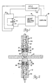
- the weld control apparatus for monitoring the progress of a spot weld and controlling the progress in real time comprises a spot welder 10 having electrodes 12 for welding a workpiece 14, an ultrasonic control circuit 16, a computer or other processor means 18, and a conventional weld controller 20.
- the two electrodes 12 are the same and each comprise a shank 22 and a weld tip 24 coupled to the shank by a taper fit. Both elements are hollow to accommodate coolant flow in the conventional manner.
- the weld tip 24 differs from an ordinary tip in that its bore terminates in a flat surface 26 to facilitate good seating of an ultrasonic transducer 28.
- a high temperature couplant in the form of a film of grease between the ultrasonic transducer 28 and the flat surface 26 insures good ultrasonic transmission.
- a water flow tube 30 within the shank 22 carries cooling water into the weld tip 24 and also provides a passage for a transducer cable 32 which carries a driving signal to or a received signal from the ultrasonic transducer 28.
- the transducer cable 32 may be routed between the water flow tube 30 and the shank 22 and out through a port, not shown, in the side of the shank.
- the ultrasonic transducer 28 is hat-shaped with a radial flange 34.
- a coil spring 36 compressed between the end of the shank 22 and the ultrasonic transducer 28, surrounds the crown of the hat and one end presses against the radial flange 34 to urge the ultrasonic transducer 28 into firm contact with the flat surface 26.
- the other end of the coil spring 36 is soldered to a washer 37 which bears against the end of the shank 22.
- the weld tip/transducer assembly has two important advantages arising from the coil spring 36 arrangement.
- the coil spring 36 assures that the ultrasonic transducer 28 makes good contact with the flat surface 26 so that the ultrasonic signal will be effectively transferred to or from the weld tip 24.
- Prior attempts at instrumenting weld tips for ultrasonics included bonding the ultrasonic transducer to the inner surface of the weld tip. Such bonding proved to be temporary since the ultrasonic transducers came loose during the rigorous welding process.
- the ultrasonic transducer if bonded to the weld tip must be discarded when the weld tip is replaced. Since weld tip life is short, that practice would be economically prohibitive.
- the ultrasonic transducer 28 when the ultrasonic transducer 28 is spring biased against the weld tip 24, replacement of the weld tip is easy and, in fact, is essentially the same as replacing a conventional non-instrumented weld tip: the weld tip is simply knocked off the shank 22 and a new one is installed with a dab of couplant grease applied to the ultrasonic transducer. The ultrasonic transducer 28 will automatically be spring biased against the flat surface 26 of the new weld tip 24.
- the ultrasonic control circuit 16 In operation of the weld control apparatus the ultrasonic control circuit 16 energizes one of the ultrasonic transducers 28 with frequency bursts at the rate of 1000 to 3000 times per second.
- the energizing frequency is determined by the transducer crystal frequency which is about 5 MHz but may be in the range of 0.1 MHz to 15 MHZ.
- the ultrasonic signal is transmitted to the other ultrasonic transducer 28 and the time of flight (or transit time) is measured by the ultrasonic control circuit 16. Any change in temperature, tip spacing or weld nugget size will change the transit time accordingly so that weld progress is instantly and accurately measured.
- the transit time is then sampled by the computer 18 once each half-cycle for analysis by comparison of differences in transit time to programmed target values according to the method to be described, and the computer, in turn, signals to the weld controller 20 any change in the weld schedule needed to optimize the weld process.
- the weld controller 20 predetermines a weld current schedule to provide energy for weld nugget formation at a given rate intended to be the optimum rate for a given weld and also sets a termination time.
- the exact conditions encountered during a particular weld may differ from the ideal due to poor part fit-up, electrode wear, or other variables.
- the method of the invention uses the time of flight information to monitor the progress of the weld, compare the progress to an optimal model, and modify the scheduled current and termination time, if required, to form an acceptable weld.
- the preferred practice is to make one transit time measurement for each half-cycle but multiple measurements in each half-cycle may be made and averaged.
- the heating rate of the workpiece as reflected in the transit time rate of change is accurately determined and must be within prescribed limits in order to form an acceptable weld nugget within the allotted time.
- the weld duration is truncated if the transit time information indicates that the weld nugget growth in the line of travel of the signal has slowed to a preset rate.
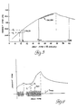
- Figure 3 shows the transit time profile for a weld between two sheets of bare steel.
- the Y-axis is transit time expressed in arbitrary units Vt and the X-axis is weld time expressed as current half-cycles.
- the slope at any point on the rising curve indicates the rate of change of transit time and is measured by the difference in transit time (Delta) over a full cycle.
- a time increment is defined by T1 and T2 when Delta is measured to determine whether the slope (rate of heating) is proper. If Delta is below a minimum (DeltaMin) the current is increased and if Delta is above a maximum (DeltaMax) the current is decreased to compensate for the discrepancy. Later in the weld cycle when the weld might be expected to be completed, a pair of limits (Tmin and Tmax) are set and Delta is measured in every half-cycle in that range and compared to a value (DeltaEnd) which indicates that the weld nugget growth has slowed to a value which indicates that the weld is complete. Then the current is terminated. If the DeltaEnd is not found the current will be terminated at Tmax by the weld controller 20.
- the workpiece was two sheets of bare steel having thicknesses of 1.85 mm and 1.12 mm (0.073 and 0.044 inch) respectively.
- the parameters for the algorithm were: As can be seen from the graph the Delta was within the prescribed limits or target range and the current was not adjusted. The second target value, DeltaEnd, was passed at half-cycle 32 and the current stopped.
- FIG. 4 Another example is shown in Figure 4 for a workpiece comprising two galvanized sheets each having a thickness of 1.32 mm (0.052 inch).
- the weld controller 20 is set to provide welding current in two stages separated by a cooling period.
- the transit time profile shows the workpiece heating and cooling as the current is applied or not.
- the current waveforms are superimposed on the graph to show each stage.
- the heating rate was quite low when sampled at T1-T2 so that the Delta was below DeltaMin.
- the current was increased resulting in larger waveform amplitudes and an increased slope of the profile.
- the half-cycles are numbered according to the actual count of current pulses so that the number does not continue to increment during the cooling period.
- the algorithm given above is directly applicable to this weld schedule and the parameters were as follows:
- a particular advantage of this control is that it terminates current at or near the optimum weld strength when the weld nugget becomes so large that its growth in the region directly between the electrodes 12 becomes slow. This is in contrast to those methods which are able to only recognize a large change in workpiece thickness which occurs at metal expulsion.
- the expulsion sensing systems can provide useful weld control on the basis that expulsion is indicative of a strong or good weld. However it is generally recognized that the weld has passed its peak strength by the time expulsion occurs so that an earlier detection can result in even stronger welds. Moreover, the splash of molten metal which can accompany expulsion is avoided.
- the computer control can be readily adapted to scheduling for multiple welds of differing types with the proper parameters programmed for each weld.
- the invention provides a practical way of accurately tracking weld progress and controlling weld parameters in real time to assure acceptable welds.
Abstract

Description
- This invention relates to a method and apparatus for controlling resistance spot welds and particularly to such a method and apparatus using ultrasonic transit time measurements which are related to weld progress.
- Many techniques have been attempted for monitoring or controlling resistance spot welds during the welding operation. These have included sensing weld resistance, acoustic emissions, weld tip displacement, and ultrasonic testing. Very few of the attempts have been commercially successful and any successes have been limited to narrow limits of operation or nearly ideal welding operations. Environments such as automotive manufacture provide less than ideal condition and varied parameters so that different metal thicknesses, number of layers, and metal coatings all challenge the ability of a given approach to weld control.
- Ultrasonics have been tried for weld monitoring with no real success prior to this invention. The usual ultrasonic method is to try to track the weld nugget growth by transmitting ultrasonic energy through the weld and analyzing the signal amplitude variations. U.S. Patent No. 3,384,733 describes an example of this type.
- Weld tip displacement has been used to track the progress of a weld and terminate the weld current when the displacement indicates that indentation has occurred. This is shown in an article by Steibel et al, entitled "Monitoring and control of spot Weld Operations", Society of Automotive Engineers, 1986. In this case the only control is the termination time, the current being controlled by a preset schedule.
- It is therefore an object of the invention to provide a method and apparatus for monitoring the progress of a weld and using a feedback control to alter the weld parameters during the weld process.
- To this end, a method of, and apparatus for, controlling a resistance spot weld is characterised by the features specified in the characterising portion of claims 1 & 4 respectively.
- The invention is carried out by the method of controlling a resistance spot weld comprising the steps of: transmitting ultrasonic pulses between spot weld tips during a weld cycle, measuring the transit time of the ultrasonic pulses to obtain weld nugget growth information, the transit time of each pulse being a function of weld nugget growth, determining the rate of transit time change from the transit times of at least two pulses, comparing the rate of transit time change to a preset range during the early portion of the weld cycle and, when there is a discrepancy, adjusting the weld current to conform the measured rate to the preset range, and comparing the rate of transit time change to a preset rate during a later portion of the weld cycle and, when the measured rate falls below the preset rate, terminating the weld current.
- The invention is further carried out by a resistance spot weld control having: monitoring means for monitoring weld progress including a coolant cavity in each weld tip, an ultrasonic transducer in each weld tip, a spring for biasing each ultrasonic transducer against the bottom of its respective coolant cavity, and a control circuit for activating the transducers and periodically measuring the transit time of ultrasonic signals between the ultrasonic transducers; and processor means programmed to a) store rate of change of transit time target values, b) calculate rate of change of transit time data values from the measured transit times, and c) compare the target values and data values to determine any substantial variation from target value and produce a current change signal to correct for such a variation.
- The present invention is now described, by way of example, with reference to the following description taken in conjunction with the accompanying drawings wherein like reference numerals refer to like parts and wherein:
- Figure 1 is a schematic diagram of a weld control apparatus according to the invention;
- Figure 2 is a cross-sectional view of welding electrodes for the weld control apparatus of Figure 1; and
- Figures 3 and 4 are graphs of the profile of transit times during welds on two different workpieces and illustrating the application of a control algorithm according to the invention.
- It has been found that the transit time of ultrasonic signals between electrode mounted ultrasonic transducers is determined by several parameters. The separation of the electrodes due to the thickness of the workpiece and portions of the electrodes establishes the nominal transit time and further separation changes due to thermal expansion and contraction effects changes in the transit time. More dominant influences in the change of transit time, however, are the effects of temperature and phase on the velocity of the ultrasonic signal. As the temperatures of the workpiece and the electrodes increases the velocity decreases; in addition, the velocity in the molten weld nugget is much lower than in the solid phase. Thus the rate of heating and melting of the workpiece is directly reflected in changes of the transit time. Thus transit time can be used to monitor the progress of a weld. The rate of change of transit time in the early portion of a weld cycle is useful as a measure of the heating rate and later, when the weld nugget is forming, is useful as a measure of the weld nugget growth.
- Referring to Figures 1 and 2, the weld control apparatus for monitoring the progress of a spot weld and controlling the progress in real time comprises a spot welder 10 having
electrodes 12 for welding aworkpiece 14, anultrasonic control circuit 16, a computer or other processor means 18, and aconventional weld controller 20. The twoelectrodes 12 are the same and each comprise ashank 22 and aweld tip 24 coupled to the shank by a taper fit. Both elements are hollow to accommodate coolant flow in the conventional manner. Theweld tip 24 differs from an ordinary tip in that its bore terminates in aflat surface 26 to facilitate good seating of anultrasonic transducer 28. A high temperature couplant in the form of a film of grease between theultrasonic transducer 28 and theflat surface 26 insures good ultrasonic transmission. Awater flow tube 30 within theshank 22 carries cooling water into theweld tip 24 and also provides a passage for atransducer cable 32 which carries a driving signal to or a received signal from theultrasonic transducer 28. Alternatively, thetransducer cable 32 may be routed between thewater flow tube 30 and theshank 22 and out through a port, not shown, in the side of the shank. Theultrasonic transducer 28 is hat-shaped with aradial flange 34. Acoil spring 36, compressed between the end of theshank 22 and theultrasonic transducer 28, surrounds the crown of the hat and one end presses against theradial flange 34 to urge theultrasonic transducer 28 into firm contact with theflat surface 26. The other end of thecoil spring 36 is soldered to awasher 37 which bears against the end of theshank 22. - The weld tip/transducer assembly has two important advantages arising from the
coil spring 36 arrangement. First, thecoil spring 36 assures that theultrasonic transducer 28 makes good contact with theflat surface 26 so that the ultrasonic signal will be effectively transferred to or from theweld tip 24. Prior attempts at instrumenting weld tips for ultrasonics included bonding the ultrasonic transducer to the inner surface of the weld tip. Such bonding proved to be temporary since the ultrasonic transducers came loose during the rigorous welding process. Moreover, the ultrasonic transducer, if bonded to the weld tip must be discarded when the weld tip is replaced. Since weld tip life is short, that practice would be economically prohibitive. Second, when theultrasonic transducer 28 is spring biased against theweld tip 24, replacement of the weld tip is easy and, in fact, is essentially the same as replacing a conventional non-instrumented weld tip: the weld tip is simply knocked off theshank 22 and a new one is installed with a dab of couplant grease applied to the ultrasonic transducer. Theultrasonic transducer 28 will automatically be spring biased against theflat surface 26 of thenew weld tip 24. - In operation of the weld control apparatus the
ultrasonic control circuit 16 energizes one of theultrasonic transducers 28 with frequency bursts at the rate of 1000 to 3000 times per second. The energizing frequency is determined by the transducer crystal frequency which is about 5 MHz but may be in the range of 0.1 MHz to 15 MHZ. The ultrasonic signal is transmitted to the otherultrasonic transducer 28 and the time of flight (or transit time) is measured by theultrasonic control circuit 16. Any change in temperature, tip spacing or weld nugget size will change the transit time accordingly so that weld progress is instantly and accurately measured. The transit time is then sampled by thecomputer 18 once each half-cycle for analysis by comparison of differences in transit time to programmed target values according to the method to be described, and the computer, in turn, signals to theweld controller 20 any change in the weld schedule needed to optimize the weld process. - Traditionally, the
weld controller 20 predetermines a weld current schedule to provide energy for weld nugget formation at a given rate intended to be the optimum rate for a given weld and also sets a termination time. The exact conditions encountered during a particular weld may differ from the ideal due to poor part fit-up, electrode wear, or other variables. To achieve adaptive control, the method of the invention uses the time of flight information to monitor the progress of the weld, compare the progress to an optimal model, and modify the scheduled current and termination time, if required, to form an acceptable weld. The preferred practice is to make one transit time measurement for each half-cycle but multiple measurements in each half-cycle may be made and averaged. - The heating rate of the workpiece as reflected in the transit time rate of change is accurately determined and must be within prescribed limits in order to form an acceptable weld nugget within the allotted time. The weld duration is truncated if the transit time information indicates that the weld nugget growth in the line of travel of the signal has slowed to a preset rate. Figure 3 shows the transit time profile for a weld between two sheets of bare steel. The Y-axis is transit time expressed in arbitrary units Vt and the X-axis is weld time expressed as current half-cycles. The slope at any point on the rising curve indicates the rate of change of transit time and is measured by the difference in transit time (Delta) over a full cycle.
- During an early portion of the weld cycle a time increment is defined by T1 and T2 when Delta is measured to determine whether the slope (rate of heating) is proper. If Delta is below a minimum (DeltaMin) the current is increased and if Delta is above a maximum (DeltaMax) the current is decreased to compensate for the discrepancy. Later in the weld cycle when the weld might be expected to be completed, a pair of limits (Tmin and Tmax) are set and Delta is measured in every half-cycle in that range and compared to a value (DeltaEnd) which indicates that the weld nugget growth has slowed to a value which indicates that the weld is complete. Then the current is terminated. If the DeltaEnd is not found the current will be terminated at Tmax by the
weld controller 20. - The method can be described by the algorithm which forms the basis for programming the computer 18:
Start weld at StartHeat:
Record Vt at T1 and T2:
Delta = V2 - V1:
If Delta < DeltaMin increase heat:
If Delta > DeltaMax decrease heat:
After Tmin determine Delta for each half-cycle:
If Delta < DeltaEnd stop the weld current:
If Tmax is reached stop the weld current.
For the particular case illustrated in Figure 3 the workpiece was two sheets of bare steel having thicknesses of 1.85 mm and 1.12 mm (0.073 and 0.044 inch) respectively. The parameters for the algorithm were:
cycle 32 and the current stopped. - Another example is shown in Figure 4 for a workpiece comprising two galvanized sheets each having a thickness of 1.32 mm (0.052 inch). The
weld controller 20 is set to provide welding current in two stages separated by a cooling period. The transit time profile shows the workpiece heating and cooling as the current is applied or not. The current waveforms are superimposed on the graph to show each stage. In this case the heating rate was quite low when sampled at T1-T2 so that the Delta was below DeltaMin. The current was increased resulting in larger waveform amplitudes and an increased slope of the profile. As Delta sampling resumed after Tmin, a decreasing slope near the peak allowed the detection of a Delta below DeltaEnd to terminate the current. The half-cycles are numbered according to the actual count of current pulses so that the number does not continue to increment during the cooling period. The algorithm given above is directly applicable to this weld schedule and the parameters were as follows: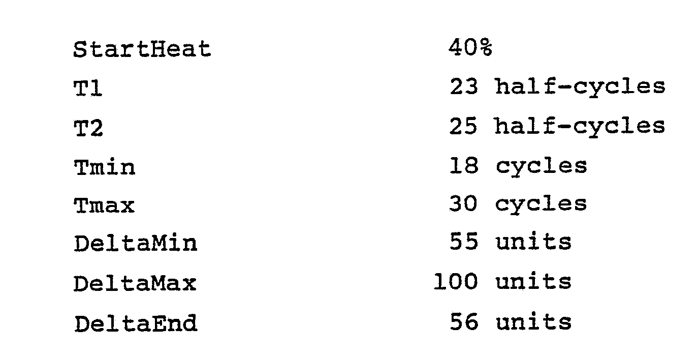
- A particular advantage of this control is that it terminates current at or near the optimum weld strength when the weld nugget becomes so large that its growth in the region directly between the
electrodes 12 becomes slow. This is in contrast to those methods which are able to only recognize a large change in workpiece thickness which occurs at metal expulsion. The expulsion sensing systems can provide useful weld control on the basis that expulsion is indicative of a strong or good weld. However it is generally recognized that the weld has passed its peak strength by the time expulsion occurs so that an earlier detection can result in even stronger welds. Moreover, the splash of molten metal which can accompany expulsion is avoided. Repeated testing of the method and apparatus of the present invention under varying conditions and for different types of welds and two or more sheets in the workpiece has yielded acceptable welds. The computer control can be readily adapted to scheduling for multiple welds of differing types with the proper parameters programmed for each weld. - It will thus be seen that the invention provides a practical way of accurately tracking weld progress and controlling weld parameters in real time to assure acceptable welds.
Claims (5)
Applications Claiming Priority (2)
| Application Number | Priority Date | Filing Date | Title |
|---|---|---|---|
| US07/023,250 US4711984A (en) | 1987-03-09 | 1987-03-09 | Ultrasonic method and apparatus for spot weld control |
| US23250 | 1987-03-09 |
Publications (2)
| Publication Number | Publication Date |
|---|---|
| EP0284177A1 true EP0284177A1 (en) | 1988-09-28 |
| EP0284177B1 EP0284177B1 (en) | 1991-01-02 |
Family
ID=21813962
Family Applications (1)
| Application Number | Title | Priority Date | Filing Date |
|---|---|---|---|
| EP88300482A Expired - Lifetime EP0284177B1 (en) | 1987-03-09 | 1988-01-21 | Method and apparatus for spot weld control |
Country Status (5)
| Country | Link |
|---|---|
| US (1) | US4711984A (en) |
| EP (1) | EP0284177B1 (en) |
| JP (1) | JPS63235082A (en) |
| CA (1) | CA1286370C (en) |
| DE (1) | DE3861337D1 (en) |
Cited By (9)
| Publication number | Priority date | Publication date | Assignee | Title |
|---|---|---|---|---|
| WO1994003799A1 (en) * | 1992-07-31 | 1994-02-17 | Fraunhofer-Gesellschaft zur Förderung der angewandten Forschung e.V. | Process for assessing welded joints |
| EP0753145A1 (en) * | 1994-07-18 | 1997-01-15 | THE BABCOCK & WILCOX COMPANY | Automated butt weld inspection system |
| EP1046452A2 (en) * | 1999-04-01 | 2000-10-25 | DaimlerChrysler Corporation | Transducer built into an electrode |
| WO2002018088A1 (en) * | 2000-09-01 | 2002-03-07 | Robert Bosch Gmbh | Device and method for determining parameters of a welding system |
| WO2003072295A1 (en) * | 2002-02-25 | 2003-09-04 | Vogt Werkstoffprüfsysteme Gmbh | Welding electrode comprising an ultrasound probe |
| EP1688738A1 (en) * | 2004-09-30 | 2006-08-09 | Daimlerchrysler Corporation | Ultrasonic in-process monitoring and feedback of resistance spot weld quality |
| WO2008019708A1 (en) | 2006-08-14 | 2008-02-21 | Ge Inspection Technologies Gmbh | Method for online ultrasound testing of a weld point produced using electrical resistance welding |
| CN102275036A (en) * | 2010-06-08 | 2011-12-14 | 小原株式会社 | Electric resistance welding device |
| US8381591B2 (en) | 2009-03-27 | 2013-02-26 | Tessonics Corporation | Electrode cap for ultrasonic testing |
Families Citing this family (21)
| Publication number | Priority date | Publication date | Assignee | Title |
|---|---|---|---|---|
| JP2510377B2 (en) * | 1992-05-01 | 1996-06-26 | 株式会社ナ・デックス | Welding controller |
| DE4335108C1 (en) * | 1993-10-14 | 1995-01-05 | Schunk Ultraschalltechnik Gmbh | Method and device for compacting and subsequent welding of electrical conductors |
| FR2745087B1 (en) * | 1996-02-20 | 2000-02-11 | Abel Georges | METHOD FOR NON-DESTRUCTIVE MEASUREMENT AND CONTROL OF RESISTANCE SPOT WELDING AND AXLE AND STUD WELDING ON SHEETS |
| JP3886603B2 (en) * | 1997-07-14 | 2007-02-28 | 株式会社ナ・デックス | Resistance welding system using cumulative heat generation per unit volume as an index |
| DE19815041C1 (en) * | 1998-04-03 | 1999-11-18 | Vogt Ingenieurbuero Dipl Ing G | Welding electrode with an arrangement for the introduction of ultrasound for testing welded connections |
| US6184491B1 (en) | 1999-11-03 | 2001-02-06 | Caterpillar Inc. | Method and apparatus for monitoring weld quality |
| US6515251B1 (en) | 2000-10-31 | 2003-02-04 | Steelcase Development Corporation | Welding system and method |
| DE10313288A1 (en) * | 2003-03-25 | 2004-10-14 | Bosch Rexroth Ag | Electrode holder with integrated ultrasonic sensor |
| US8183493B2 (en) * | 2005-09-28 | 2012-05-22 | General Electric Company | Ultrasonic system for monitoring a weld operation |
| US8847100B2 (en) * | 2008-01-08 | 2014-09-30 | Fanuc America Corporation | Weld cap and tip inspection method and apparatus |
| JP5236385B2 (en) * | 2008-08-04 | 2013-07-17 | 本田技研工業株式会社 | Melting zone interface position detection method and apparatus |
| FR2935050B1 (en) * | 2008-08-13 | 2011-02-25 | Areva Np | DEVICE AND METHOD FOR ULTRASOUND MONITORING, MEASUREMENT AND TRACKING OF A HOT WELD CORD BETWEEN TWO METAL PIECES |
| JP5209749B2 (en) * | 2011-03-04 | 2013-06-12 | 株式会社豊田中央研究所 | Resistance welding method, resistance welding member, resistance welding machine and its control device, resistance welding machine control method and control program, resistance welding evaluation method and evaluation program |
| US20140255620A1 (en) * | 2013-03-06 | 2014-09-11 | Rolls-Royce Corporation | Sonic grain refinement of laser deposits |
| ES2585703B1 (en) * | 2015-04-07 | 2017-04-18 | Sgs Tecnos, S.A. | Refrigerator system for ultrasonic probes |
| CN107478721A (en) * | 2016-06-08 | 2017-12-15 | 武汉理工大学 | A kind of point quality real-time ultrasound the cannot-harm-detection device and method |
| CN107478720A (en) * | 2016-06-08 | 2017-12-15 | 武汉理工大学 | A kind of device and method for detecting point quality in real time using ultrasonic penetration signal |
| CN106064282A (en) * | 2016-07-13 | 2016-11-02 | 吉林大学 | Joint for resistance spot welding quality ultrasound ripple online monitoring system and method |
| CN110064831A (en) * | 2018-01-23 | 2019-07-30 | 长沙芬贝电子科技有限公司 | It is a kind of can real-time detection solder joint welder and welding method |
| CN112285211A (en) * | 2020-11-03 | 2021-01-29 | 吉林大学 | Resistance spot welding quality detection device and method |
| WO2023015030A1 (en) * | 2021-08-06 | 2023-02-09 | Tessonics Corp. | Comprehensive real-time characterization of ultrasonic signatures from nondestructive evaluation of resistance spot welding process using artificial intelligence |
Citations (5)
| Publication number | Priority date | Publication date | Assignee | Title |
|---|---|---|---|---|
| US3384733A (en) * | 1964-07-20 | 1968-05-21 | Army Usa | Ultrasonic inspection system and apparatus for resistance welds and the like |
| GB1146907A (en) * | 1965-06-08 | 1969-03-26 | Deutsch Karl | Method of and apparatus for the non-destructive testing of spot welds and other pressure welds |
| US4449029A (en) * | 1983-05-09 | 1984-05-15 | General Electric Company | Acoustic wave spot welder adaptive control |
| US4472620A (en) * | 1983-04-01 | 1984-09-18 | General Electric Company | Instrumented spot welding electrode |
| US4596917A (en) * | 1984-01-16 | 1986-06-24 | General Electric Company | Resistance spot welder process monitor |
Family Cites Families (8)
| Publication number | Priority date | Publication date | Assignee | Title |
|---|---|---|---|---|
| DE1473400A1 (en) * | 1962-05-23 | 1969-01-09 | Deutsch Pruef Messgeraete | Process and device for non-destructive testing of spot and other pressure welds |
| US3726130A (en) * | 1970-12-09 | 1973-04-10 | Budd Co | Method of monitoring a welding operation |
| US3810385A (en) * | 1971-02-22 | 1974-05-14 | Mc Donnell Douglas Corp | Transducer means for ultrasonic extensometer |
| JPS5269683A (en) * | 1975-12-08 | 1977-06-09 | Mitsubishi Electric Corp | Method and device for ultrasonic inspection of resistance welding |
| JPS52105548A (en) * | 1976-03-02 | 1977-09-05 | Mitsubishi Electric Corp | Apparatus for resistance welding with automatic control using supersonic waves |
| JPS5588988A (en) * | 1978-12-27 | 1980-07-05 | Toshiba Corp | Ultrasonic detecting device for resistance welding |
| JPS5634861U (en) * | 1979-08-23 | 1981-04-04 | ||
| FR2538562B1 (en) * | 1982-12-27 | 1985-07-19 | Inst Francais Du Petrole | METHOD AND APPARATUS FOR DETECTING FRACTURES BY ULTRASONIC ECHOGRAPHY ALONG THE WALL OF A MATERIAL OR FORMATION |
-
1987
- 1987-03-09 US US07/023,250 patent/US4711984A/en not_active Expired - Fee Related
- 1987-12-01 CA CA000553200A patent/CA1286370C/en not_active Expired - Fee Related
-
1988
- 1988-01-21 DE DE8888300482T patent/DE3861337D1/en not_active Expired - Fee Related
- 1988-01-21 EP EP88300482A patent/EP0284177B1/en not_active Expired - Lifetime
- 1988-03-09 JP JP63053862A patent/JPS63235082A/en active Pending
Patent Citations (5)
| Publication number | Priority date | Publication date | Assignee | Title |
|---|---|---|---|---|
| US3384733A (en) * | 1964-07-20 | 1968-05-21 | Army Usa | Ultrasonic inspection system and apparatus for resistance welds and the like |
| GB1146907A (en) * | 1965-06-08 | 1969-03-26 | Deutsch Karl | Method of and apparatus for the non-destructive testing of spot welds and other pressure welds |
| US4472620A (en) * | 1983-04-01 | 1984-09-18 | General Electric Company | Instrumented spot welding electrode |
| US4449029A (en) * | 1983-05-09 | 1984-05-15 | General Electric Company | Acoustic wave spot welder adaptive control |
| US4596917A (en) * | 1984-01-16 | 1986-06-24 | General Electric Company | Resistance spot welder process monitor |
Cited By (14)
| Publication number | Priority date | Publication date | Assignee | Title |
|---|---|---|---|---|
| WO1994003799A1 (en) * | 1992-07-31 | 1994-02-17 | Fraunhofer-Gesellschaft zur Förderung der angewandten Forschung e.V. | Process for assessing welded joints |
| DE4325856A1 (en) * | 1992-07-31 | 1994-02-24 | Fraunhofer Ges Forschung | Method for assessment of welded joints using ultrasound |
| EP0753145A1 (en) * | 1994-07-18 | 1997-01-15 | THE BABCOCK & WILCOX COMPANY | Automated butt weld inspection system |
| EP0753145A4 (en) * | 1994-07-18 | 1997-04-02 | Babcock & Wilcox Co | Automated butt weld inspection system |
| EP1046452A3 (en) * | 1999-04-01 | 2002-06-12 | DaimlerChrysler Corporation | Transducer built into an electrode |
| EP1046452A2 (en) * | 1999-04-01 | 2000-10-25 | DaimlerChrysler Corporation | Transducer built into an electrode |
| WO2002018088A1 (en) * | 2000-09-01 | 2002-03-07 | Robert Bosch Gmbh | Device and method for determining parameters of a welding system |
| US7004370B2 (en) | 2000-09-01 | 2006-02-28 | Robert Bosch Gmbh | Device and method for determining parameters of a welding system |
| WO2003072295A1 (en) * | 2002-02-25 | 2003-09-04 | Vogt Werkstoffprüfsysteme Gmbh | Welding electrode comprising an ultrasound probe |
| EP1688738A1 (en) * | 2004-09-30 | 2006-08-09 | Daimlerchrysler Corporation | Ultrasonic in-process monitoring and feedback of resistance spot weld quality |
| WO2008019708A1 (en) | 2006-08-14 | 2008-02-21 | Ge Inspection Technologies Gmbh | Method for online ultrasound testing of a weld point produced using electrical resistance welding |
| US8381591B2 (en) | 2009-03-27 | 2013-02-26 | Tessonics Corporation | Electrode cap for ultrasonic testing |
| CN102275036A (en) * | 2010-06-08 | 2011-12-14 | 小原株式会社 | Electric resistance welding device |
| CN102275036B (en) * | 2010-06-08 | 2015-11-25 | 小原株式会社 | Electric resistance welder |
Also Published As
| Publication number | Publication date |
|---|---|
| US4711984A (en) | 1987-12-08 |
| JPS63235082A (en) | 1988-09-30 |
| EP0284177B1 (en) | 1991-01-02 |
| CA1286370C (en) | 1991-07-16 |
| DE3861337D1 (en) | 1991-02-07 |
Similar Documents
| Publication | Publication Date | Title |
|---|---|---|
| EP0284177B1 (en) | Method and apparatus for spot weld control | |
| US4734555A (en) | Method and apparatus for measuring and controlling indentation in resistance welding | |
| US5920014A (en) | Process for assessing welded joints | |
| US4449029A (en) | Acoustic wave spot welder adaptive control | |
| EP1688738A1 (en) | Ultrasonic in-process monitoring and feedback of resistance spot weld quality | |
| EP0110523B1 (en) | Ultrasonic control of welding | |
| US6906276B2 (en) | Resistance spot welding control device and method | |
| JPH0316233B2 (en) | ||
| US20030167846A1 (en) | Method and apparatus for the production and quality testing of a bonded wire connection | |
| US4376884A (en) | Closed loop control of continuous seam resistance heated forge welding cylinders | |
| US4447699A (en) | Closed loop control of continuous seam resistance heated forge welding cylinders | |
| JPH0671457A (en) | Resistance welding controller | |
| KR102166234B1 (en) | System and method for resistance spot welding control | |
| US5958263A (en) | Stud welding method | |
| WO1988000104A2 (en) | Method and apparatus for measuring and controlling indentation in resistance welding | |
| JP2002316269A (en) | Monitoring device for spot welding | |
| JP3796746B2 (en) | Spot welding equipment | |
| SU1715532A1 (en) | Method of monitoring resistance spot welding process | |
| JP7258445B2 (en) | CONTROL DEVICE FOR RESISTANCE WELDING MACHINE, METHOD FOR MONITORING ELECTRICAL CONDITION OF WELDED PORTION, AND METHOD FOR JUDGING GOOD OR FAILURE | |
| JP3703017B2 (en) | Spot welding monitoring method and monitoring apparatus | |
| JP2001025880A (en) | Spot welding equipment | |
| SU1016110A1 (en) | Method of automatic control of resistance spot welding with applying ultrasonic oscillations | |
| JP3705057B2 (en) | Spot welding equipment | |
| CN108637448B (en) | Method for monitoring heterogeneous metal ultrasonic welding edge cracks | |
| Hall et al. | Bonded joints and non-destructive testing: NDT of resistance spots, roll-spot, stitch and seam welds |
Legal Events
| Date | Code | Title | Description |
|---|---|---|---|
| PUAI | Public reference made under article 153(3) epc to a published international application that has entered the european phase |
Free format text: ORIGINAL CODE: 0009012 |
|
| AK | Designated contracting states |
Kind code of ref document: A1 Designated state(s): DE FR GB |
|
| 17P | Request for examination filed |
Effective date: 19881121 |
|
| 17Q | First examination report despatched |
Effective date: 19891227 |
|
| GRAA | (expected) grant |
Free format text: ORIGINAL CODE: 0009210 |
|
| AK | Designated contracting states |
Kind code of ref document: B1 Designated state(s): DE FR GB |
|
| REF | Corresponds to: |
Ref document number: 3861337 Country of ref document: DE Date of ref document: 19910207 |
|
| ET | Fr: translation filed | ||
| PLBE | No opposition filed within time limit |
Free format text: ORIGINAL CODE: 0009261 |
|
| STAA | Information on the status of an ep patent application or granted ep patent |
Free format text: STATUS: NO OPPOSITION FILED WITHIN TIME LIMIT |
|
| 26N | No opposition filed | ||
| PGFP | Annual fee paid to national office [announced via postgrant information from national office to epo] |
Ref country code: GB Payment date: 19941228 Year of fee payment: 8 |
|
| PGFP | Annual fee paid to national office [announced via postgrant information from national office to epo] |
Ref country code: FR Payment date: 19950130 Year of fee payment: 8 |
|
| PGFP | Annual fee paid to national office [announced via postgrant information from national office to epo] |
Ref country code: DE Payment date: 19950313 Year of fee payment: 8 |
|
| PG25 | Lapsed in a contracting state [announced via postgrant information from national office to epo] |
Ref country code: GB Effective date: 19960121 |
|
| GBPC | Gb: european patent ceased through non-payment of renewal fee |
Effective date: 19960121 |
|
| PG25 | Lapsed in a contracting state [announced via postgrant information from national office to epo] |
Ref country code: FR Effective date: 19960930 |
|
| PG25 | Lapsed in a contracting state [announced via postgrant information from national office to epo] |
Ref country code: DE Effective date: 19961001 |
|
| REG | Reference to a national code |
Ref country code: FR Ref legal event code: ST |