EP0283941A2 - Cathode ray tube having an electron gun constructed for readay refocusing of the electron beam - Google Patents
Cathode ray tube having an electron gun constructed for readay refocusing of the electron beam Download PDFInfo
- Publication number
- EP0283941A2 EP0283941A2 EP88104288A EP88104288A EP0283941A2 EP 0283941 A2 EP0283941 A2 EP 0283941A2 EP 88104288 A EP88104288 A EP 88104288A EP 88104288 A EP88104288 A EP 88104288A EP 0283941 A2 EP0283941 A2 EP 0283941A2
- Authority
- EP
- European Patent Office
- Prior art keywords
- lens
- quadrupolar
- electrodes
- group
- potential
- Prior art date
- Legal status (The legal status is an assumption and is not a legal conclusion. Google has not performed a legal analysis and makes no representation as to the accuracy of the status listed.)
- Granted
Links
Images


Classifications
-
- H—ELECTRICITY
- H01—ELECTRIC ELEMENTS
- H01J—ELECTRIC DISCHARGE TUBES OR DISCHARGE LAMPS
- H01J29/00—Details of cathode-ray tubes or of electron-beam tubes of the types covered by group H01J31/00
- H01J29/46—Arrangements of electrodes and associated parts for generating or controlling the ray or beam, e.g. electron-optical arrangement
- H01J29/58—Arrangements for focusing or reflecting ray or beam
- H01J29/62—Electrostatic lenses
-
- H—ELECTRICITY
- H01—ELECTRIC ELEMENTS
- H01J—ELECTRIC DISCHARGE TUBES OR DISCHARGE LAMPS
- H01J31/00—Cathode ray tubes; Electron beam tubes
- H01J31/08—Cathode ray tubes; Electron beam tubes having a screen on or from which an image or pattern is formed, picked up, converted, or stored
- H01J31/10—Image or pattern display tubes, i.e. having electrical input and optical output; Flying-spot tubes for scanning purposes
- H01J31/12—Image or pattern display tubes, i.e. having electrical input and optical output; Flying-spot tubes for scanning purposes with luminescent screen
- H01J31/121—Image or pattern display tubes, i.e. having electrical input and optical output; Flying-spot tubes for scanning purposes with luminescent screen tubes for oscillography
Definitions
- Our invention relates to cathode ray tubes (CRTs) such as those used for oscilloscopic and storage applications. More specifically, our invention pertains to improvements in or relating to CRTs of the type having a plurality of quadrupolar lenses arranged in a row along the tube axis as parts of the electron gun, the improvements being designed for easy refocusing of the beam at the screen or target.
- CRTs cathode ray tubes
- the cathode of the electron gun emits a beam of electrons following different paths depending upon a potential impressed to the control electrode. Varying the potential on the control electrode alters the paths of the electrons and thus changes the position in which they converge or cross over on the tube axis. In the prior art CRTs having three quadrupolar lenses, such shifting of the crossover point on the tube axis has required readjustment of as many as three different potentials, or even six different potentials consisting of three different positive potentials and three different negative potentials, on the constituent electrodes of the quadrupolar lenses in order to refocus the beam at the target.
- our invention is best characterized by a unipotential refocusing lens provided between the crossover point and the series of quadrupolar lenses for providing a converging lens action of radial symmetry about the tube axis.
- the electron beam on being defocused by a change in the potential on the control electrode, can be refocused by adjusting a single potential on the refocusing lens instead of several potentials on the quadrupolar lenses.
- the CRT 20 has a hermetically sealed, evacuated envelope 22 of glass or like rigid, electrically insulating material.
- the envelope 22 has a funnel portion 24 and a tubular neck portion 26 integrally joined to each other in alignment about their central axis z .
- This central axis z of the envelope 22 as the tube axis or z axis, as the case may be.
- the envelope funnel portion 24 has a target 28 formed on the inner surface of a glass faceplate 30 constituting part of the envelope 22.
- the target 28 takes the form of a fluorescent screen in this particular embodiment, comprising a conductive layer 32 overlying a fluorescent coating 34 on the faceplate.
- the electron gun 36 for emitting electrons in a beam B directed toward the target 28.
- the electron gun 36 comprises a cathode 38, a control electrode 40, an accelerating electrode 42, a refocusing lens 44, and first 46, second 48 and third 50 unipotential quarupolar lenses, which are arranged in that order from the gun side end toward the target side end of the envelope 22 along the tube axis z .
- the envelope neck portion 26 further houses a pair of vertical deflection plates 54 disposed between the second 48 and third 50 quadrupolar lenses, and a pair of horizontal deflection plates 56 disposed between the third quadrupolar lens 50 and the target 28.
- the deflection plate pairs 54 and 56 operate in the known manner to deflect the electron beam B vertically and horizontally, respectively.
- the refocusing lens 44 constituting the gist of our invention is a unipotential electrostatic lens capable of providing a converging lens action of radial symmetry about the tube axis z for controlling the spot size of the electron beam B at the target 28. It comprises three spaced apart, planar electrodes 58, 60 and 62, herein shown as discs having apertures or holes 64, 66 and 68 of circular shape defined centrally therein, which are arranged in a row and in alignment about the tube axis z .
- first or cathode side electrode 58 and third or target side electrode 62 of the refocusing lens 44 are both electrically connected to the same supply terminal 70 as is the accelerating electrode 42.
- the second or intermediate refocusing electrode 60 is electrically connected to a dif ferent supply terminal 72 via a variable resistor 74.
- the variable potential applied to the intermediate refocusing electrode 60 is lower than the fixed potential applied to the other two refocusing electrodes 58 and 62 as well as to the accelerating electrode 42.
- the first quadrupolar lens 46 is an alternating arrangement of a first group of three planar or disclike electrodes 76 and a second group of three similar electrodes 78, all in alignment about the tube axis z and with constant spacings l therebetween.
- the first group of electrodes 76 are jointly connected to a negative supply terminal 80 via a variable resistor 82.
- the second group of electrodes 78 are jointly connected to a positive supply terminal 84 via a variable resistor 86.
- FIG. 4 shows in perspective one of the first group of electrodes 76, and one of the second group of electrodes 78, of the first quadrupolar lens 46 in their relative angular positions about the tube axis, it being understood that the two others of the first group of electrodes and the two others of the second group of electrodes are identical in construction with the two representative electrodes 76 and 78, respectively, shown here. It will be seen that each first electrode 76 and each second electrode 78 have apertures 88 and 90 formed respectively therein.
- the aperture is defined by a first pair of opposite convex edges 92 disposed in symmetrically on both sides of the yz plane, and a second pair of opposite concave edges 94 disposed symmetrically on both sides of the xz plane.
- the distance b is significantly more than, typically twice, the distance a .
- the aperture 90 in each second electrode 78 of the first quadrupolar lens 46 is identical in shape and size with the above described aperture 88 in each first electrode 76 thereof; only, the aperture 90 is angularly displaced 90 degrees about the tube axis z from the aperture 88.
- the aperture 90 is defined by a pair of opposed convex edges 96 disposed symmetrically on both sides of the xz plane and by a pair of opposed concave edges 98 disposed symmetrically on both sides of the yz plane.
- the second quadrupolar lens 48 is also an alternating arrangement of a first group of three planar or disclike electrodes 100 and a second group of three similar electrodes 102, all in alignment about the tube axis z and with constant spacings therebetween.
- the first group of electrodes 100 are jointly connected to a negative supply terminal 104 via a variable resistor 106.
- the second group of electrodes 102 are jointly connected to a positive supply terminal 108 via a variable resistor 110.
- the third quadrupolar lens 50 is likewise an alternating arrangement of a first group of three planar or disclike electrodes 112 and a second group of three similar electrodes 114, all in alignment about the tube axis z and with constant spacings therebetween.
- the first group of electrodes 112 are jointly connected to a negative supply terminal 116 via a variable resistor 118.
- the second group of electrodes 114 are jointly connected to a positive supply terminal 120 via a variable resistor 122.
- the second 48 and third 50 quadrupolar lenses are each constructed on the same principle as is the first quadrupolar lens 46.
- the second group of electrodes 102 of the second quadrupolar lens 48 and the first group of electrodes 112 of the third quadrupolar lens 50 have each an aperture of substantially the same shape and size as the aperture 88 of each of the first group of electrodes 76 of the first quadrupolar lens 46.
- the first group of electrodes 100 of the second quadrupolar lens 48 and the second group of electrodes 114 of the third quadrupolar lens 50 have each an aperture of substantially the same shape and size as the aperture 90 of each of the second group of electrodes 78 of the first quadrupolar lens 46.
- crossover point At 124 in FIG. 6 is indicated the crossover point at which the paths of the electrons issuing from the cathode 38 under the control of the control electrode 40 converge and cross over on the tube axis z .
- This crossover point is also indicated by the same reference numeral in FIG. 1.
- FIG. 6 we have disregarded the focusing action of the refocusing electrode 44 in order to clearly illustrate the actions of only the three quadrupolar lenses 46, 48 and 50.
- the refocusing of the beam has heretofore required the readjustment of the total of six (three positive and three negative) potentials on the three quadrupolar lenses 46, 48 and 50.
- We have materially simplified such beam refocusing by interposing the refocusing lens 44 between the crossover point 124 and the first quadrupolar lens 46.
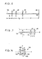
- FIG. 7 is explanatory of how the beam B is refocused through a simple readjustment of the potential on only the refocusing lens 44 which is herein shown as a convex lens by optical analogy.
- the crossover point of the convergent electron beam issuing from the cathode 38 has shifted from 124 to 124 ⁇ along the tube axis z through a change in the potential on the control electrode 40, resulting in the defocusing of the beam which has been in focus through preadjustment of the six required operating voltages on the three quadrupolar lenses 46, 48 and 50.
- the defocusing is attributable in this case to the decrease of the distance between the crossover point and the center of the first quadrupolar lens 46 from W to W1 because of the displacement of the crossover point from 124 to 124 ⁇ .
- This readjustment of the potential on the refocusing 44 is tantamount to returning the image point of the first quadrupolar lens 46 to a position of the distance W from that of the distance W1, that is, to returning the crossover point from 124 ⁇ to 124. It is thus seen that the beam B can be refocused at the target 28 only through readjustment of the potential on the refocusing lens 44. No alteration of the preadjusted potentials on the three quadrupolar lenses 46, 48 and 50 is required.
- the conventional refocusing operation by the three quadrupolar lenses 46, 48 and 50 has been very poor in response by reason of the large capacitances between their six constituent electrodes.
- the total capacitance of the three element refocusing lens 44 in accordance with our invention is so much less than that of the quadrupolar lenses 46, 48 and 50 that its response is far quicker than heretofore.
- the refocusing lens 44 of our invention lends itself to use in a CRT 20 a having a scan expansion lens system 128 of the type described and claimed in the noted European Patent Application Publication No. 241,945.
- the scan expansion lens system 128 Disposed between the pair of horizontal deflection plates 56 and the target 28, the scan expansion lens system 128 is a bipotential quadrupolar lens comprising first 130 and second 132 boxlike electrodes, with the first electrode 130 disposed closer to the electron gun 36 and partly nested in the second electrode 132 with an insulating gap therebetween.
- the CRT 20 a additionally comprises a postaccelerating electrode 134 herein shown as a conductive coating on the inside surface of the funnel portion 24 of the envelope 22 in electrically conducting relation to the conductive layer 32 of the target 28.
- the postaccelerating electrode 134 is further electrically connected to the second or target side electrode 132 of the scan expansion lens systems 128.
- the gun side electrode 130 is grounded.
- the CRT 20 a is akin in the other details of construction to the CRT 20 of FIG. 1.
- the gun side electrode 130 comprises a first pair of opposite sides 136 disposed symmetrically on both sides of the xz plane and having a pair of tongues 138 extending therefrom toward the target, and a second pair of opposite sides 140 disposed symmetrically on both sides of the yz plane and each having a side edge 142 that is curved in an arc convexed toward the electron gun.
- the target side electrode 132 comprises a first pair of opposite sides 144 disposed symmetrically on both sides of the xz plane, and a second pair of opposite sides 146 disposed symmetrically on both sides of the yz plane.
- the four sides 136 and 140 of the gun side electrode 130 and the four sides 144 and 146 of the target side electrode 132 are all convexed toward the tube axis z with a hyperbolic or similar curve.
- FIG. 10 At (A) and (B) in FIG. 10 are illustrated by optical analogy the vertical and horizontal focusing actions, respectively, of the three quadrupolar lenses 46, 48 and 50 and scan expansion lens system 128 of the CRT 20 a .
- the scan expansion lens system 128 acts as a converging lens vertically and as a diverging lens horizontally.
- the converging lens is disposed at a distance P1 from the third quadrupolar lens 50, and the diverging lens at a different distance P2 therefrom, because of the different locations in which they are created within the scan expansion lens system 128.
- FIGS. 11 and 12 are explanatory of how the scan expansion lens system 128 operates to magnify the horizontal and vertical deflections, respectively, of the electron beam.
- FIG. 11 shows at 148 the horizontal distribution of equipotential lines created largely between the pair of tongues 138 of the gun side electrode 130 of the scan expansion lens system 128 upon application of prescribed potentials to its two constituent electrodes 130 and 132.
- the line 150 indicates one of the opposite extreme trajectories of the electron beam that has been deflected horizontally.
- the equipotentials 148 act to magnify the horizontal deflection of the beam as represented by the line 150.
- FIG. 12 is shown the vertical distribution of equipotential lines 152 created adjacent the target side ends of the gun side electrode tongues 138 of the scan expansion lens system 128.
- lines 154 representing some of the trajectories of the beam that has been deflected vertically
- the equipotentials 152 expand the vertical beam deflection by inverting the trajectories 154 with respect to the z axis in the vertical plane.
- FIG. 13 shows a further preferred form of CRT 20 b in accordance with our invention.
- This CRT 20 b is analogous in construction with the FIG. 1 CRT 20 except for different means employed for applying potentials to the three quadrupolar lenses 46, 48 and 50.
- the first groups of electrodes 76, 100 and 112 of all the quadrupolar lenses 46, 48 and 50 are connected in common to a negative supply terminal 156 via a variable resistor 158.
- the second groups of electrodes 78, 102 and 114 of all the quadrupolar lenses 46, 48 and 50 are connected in common to a positive supply terminal 160 via a variable resistor 162.
- the negative potential -V impressed to the first groups of electrodes 76, 100 and 112 is equal in absolute value to the positive potential +V applied to the second groups of electrodes 78, 102 and 114.
- FIG. 14 shows a prior art unipotential quadrupolar lens 164 of seemingly ideal design. It comprises a first pair of opposed electrodes 166 convexed toward each other and disposed symmetrically on both sides of the yz plane, and a second pair of opposed electrodes 168 also convexed toward each other and disposed symmetrically on both sides of the xz plane.
- a negative voltage -V is impressed to the first pair of electrodes 166, and a positive voltage +V to the second pair of electrodes 168.
- a1, a2, a3, L1, L2 and L3 may be determined as follows in order to enable the application of the voltages +V and 1V of the same absolute value to the three quadrupolar lenses 46, 48 and 50 as in the CRT 20 b of FIG. 13.
- the values of A1, L1 and V for the first quadrupolar lens 46 may be determined in accordance with Equations (1) and (10).
- the values of w, d, q and p in Equation (1) are determined by the arrangement of the pertinent components of the CRT, and so is the value of S1. It is therefore easy to determine the values of a1, L1 and V in accordance with Equation (10) so as to meet the known value of S1.
- Equations (15) and (16) can be rewritten as:
- Equation (17) The values of a1, q, d and w in Equation (17) are known. Therefore, if the apex a2 of the hyperbola of the second quadrupolar lens 48 is determined so as to satisfy Equation (17), it follows that the same potential can be impressed to the second quadrupolar lens 48 as to the first quadrupolar lens 46.
- Equation (18) If we know the value of A2 from Equation (17), the value of A3 is ascertainable from Equation (18). Consequently, the same potential can be impressed to the third quadrupolar lens 50 as to the first 46 and second 48 quadrupolar lenses if the apex a3 of the hyperbola of the third quadrupolar lens 50 is determined so as to satisfy Equation (18).
- the application of positive and negative voltages of the same absolute value to the three quadrupolar lenses 46, 48 and 50 becomes possible if, after determination of the axial length L1 of the first lens 46, the axial lengths L2 and L3 of the second 48 and third 50 lenses are determiend so as to satisfy Equations (19) and (20).
- the required axial lengths L1, L2 and L3 of the quadrupolar lenses 46, 48 and 50 may be realized by adjustment of either the spacings l between their constituent electrodes 76, 78, 100, 102, 112 and 114 or the numbers of such electrodes.
- the electron beam B may be focused on the target 28 by application of the appropriate positive and negative voltages of the same absolute value to the three quadrupolar lenses 46, 48 and 50.
- the beam will defocus, however, if the voltage on the control electrode 40 is altered, as has been explained in connection with the FIG. 1 CRT 20. In that case the beam may be refocused by readjustment of the voltage on the refocusing lens 44 rather than of the voltages on the quadrupolar lenses 46, 48 and 50.
- the CRT 20 b possesses the advantage over the FIG. 1 CRT 20 or FIG. 8 20 a that the three quadrupolar lenses 46, 48 and 50 demand only two positive and negative voltage sources.
- the simpler voltage source means of the CRT 20 b makes the complete CRT system appreciably smaller in size and less expensive in construction.
- the CRT 20 c shown in FIG. 15 is equivalent to the FIG. 8 CRT 20 a in having the scan expansion lens system 128, and to the FIG. 13 CRT 20 b in having the means for impressing only two different potentials to the three quadrupolar lenses 46, 48 and 50.
- the other constructional details of the CRT 20 c can be as set forth in connection with the FIG. 1 CRT 20.
- the CRT 20 d shown in FIG. 16 is similar in construction to the FIG. 8 CRT 20 a except that the first quadrupolar lens 46 of the latter is absent from the former.
- the CRT 20 d has but two quadrupolar lenses 46 and 48, one between refocusing lens 44 and vertical deflection plate pair 54, and the other between vertical and horizontal deflection plate pairs 54 and 56.
- the two quadrupolar lenses 46 and 48 coact with the scan expansions lens system 128 for focusing the beam B at the target 28, as will be detailed subsequently. Therefore, in this embodiment, the scan expansion lens system 128 may be thought of as the third quadrupolar lens.
- FIG. 17 illustrates at (A) and (B) how the two quadrupolar lenses 48 and 50 and scan expansion lens system 128 of the CRT 20 d act to focus the electron beam B at the target 28 in vertical and horizontal directions, respectively.
- the first quadrupolar lens 48 acts as a converging lens vertically and as a diverging lens horizontally.
- the second quadrupolar lens 50 acts as a diverging lens vertically and as a converging lens horizontally.
- the scan expansion lens system 128 provides two successive converging lenses Q1 and Q2 vertically and a diverging lens Q3 horizontally.
- the vertical focusing action of the complete lens system is such that the elec tron beam B, diverging after having been focused at the crossover point 124, is converged by the first quadrupolar lens 48, and then diverged by the second quadrupolar lens 50 so that the electrons follow nearly parallel paths.
- the beam B is first strongly converged by the first lens Q1 and, impinging on the second lens Q2 in a diverging state, is thereby reconverged and focused at the target 28.
- the electron beam B is diverged by the first quadrupolar lens 48, then converged by the second quadrupolar lens 50, and then diverged by the lens Q3 of the scan expansion lens system 128, thereby to be focused at the target 28.
- Equation (21) The values of ⁇ , ⁇ and ⁇ may be computed from Equations (22), (23), (24) and (25). Then, substituting the computed values in Equation (21), we find that the distance w approximatley equals the distance d . It has now been seen that a round spot results from the system of two unipotential quadrupolar lenses 13 and 14 and one bipotential scan expansion lens 128 if the distances w and d are set approximately equal to each other.
- the beam will defocus if the crossover point 124 is displaced along the tube axis with a change in the potential on the control electrode 40. In that case the beam may be refocused by correspondingly varying the potential on the refocusing lens 44.
- This CRT 20 d is notable for its simplicity of construction and capability of deflection amplification.
- FIG. 18 shows a slight modification of the FIG. 13 CRT 20 b and FIG. 15 CRT 20 c .
- Positive and negative voltaged +V1 and -V1 of the same absolute value are impressed to only two (e.g. first and second) of the three quadrupolar lenses 46, 48 and 50 in this modification, instead of to all of the three quadrupolar lenses as in the CRTs 20 b and 20 c .
- Positive and negative voltages +V2 and -V2 of a different absolute value are impressed to the other one (e.g. third) quadrupolar lens.
- the distances w and q in FIG. 6 may be set equal to each other. Further, a 1 and b 1 may be set equal to a 2 and b 2, respectively.
Abstract
Description
- Our invention relates to cathode ray tubes (CRTs) such as those used for oscilloscopic and storage applications. More specifically, our invention pertains to improvements in or relating to CRTs of the type having a plurality of quadrupolar lenses arranged in a row along the tube axis as parts of the electron gun, the improvements being designed for easy refocusing of the beam at the screen or target.
- It has been known to incorporate three quadrupolar lenses in the electron gun of CRTs and to connect them to separate variable potential sources. European Patent Application Publication No. 241,945 and Japanese Laid Open Patent Application No. 59-134531 are examples of prior art teaching such quadrupolar lenses. Supplied with proper operating potentials, the quadrupolar lenses conjointly serve to create a beam spot on the target with a minimum of out-of-roundness. A problem has existed, however, with this known type of CRT in connection with the focusing of the electron beam at the target, as discussed in more detail hereafter.
- The cathode of the electron gun emits a beam of electrons following different paths depending upon a potential impressed to the control electrode. Varying the potential on the control electrode alters the paths of the electrons and thus changes the position in which they converge or cross over on the tube axis. In the prior art CRTs having three quadrupolar lenses, such shifting of the crossover point on the tube axis has required readjustment of as many as three different potentials, or even six different potentials consisting of three different positive potentials and three different negative potentials, on the constituent electrodes of the quadrupolar lenses in order to refocus the beam at the target.
- We have hereby succeeded in materially simplifying the refocusing of the electron beam at the target or screen in CRTs of the class defined after each alteration in the crossover point of the beam on the tube axis through a change in the potential on the control electrode of the electron gun.
- In summary, our invention is best characterized by a unipotential refocusing lens provided between the crossover point and the series of quadrupolar lenses for providing a converging lens action of radial symmetry about the tube axis. Thus the electron beam, on being defocused by a change in the potential on the control electrode, can be refocused by adjusting a single potential on the refocusing lens instead of several potentials on the quadrupolar lenses.
- The above and other features and advantages of our invention and the manner of realizing them will become more apparent, and the invention itself will best be understood, from a study of the following description and appended claims, with reference had to the attached drawings showing several preferable embodiments of our invention.
-
- FIG. 1 is a diagrammatic longitudinal section through the CRT constructed in accordance with our invention, the CRT being shown together with means for applying potentials to its various working components;
- FIG. 2 is an enlarged view in perspective of the refocusing lens in the FIG. 1 CRT;
- FIG. 3 is an enlarged axial section through the first quadrupolar lens in the FIG. 1 CRT;
- FIG. 4 is an enlarged view in perspective of two representative ones of the constituent electrodes of the first quadrupolar lens in the FIG. 1 CRT;
- FIG. 5 is a still more enlarged elevation of one of the two representative electrodes of FIG. 4;
- FIG. 6 is an illustration by optical analogy of the focusing actions of the three quadrupolar lenses of the FIG. 1 CRT in two orthogonal directions;
- FIG. 7 is an illustration by optical analogy of how the refocusing lens operates to refocus the electron beam in the FIG. 1 CRT;
- FIG. 8 is a diagrammatic longitudinal section through another preferred form of CRT constructed in accordance with our invention, the CRT being shown together with means for applying potentials to its various working components;
- FIG. 9 is an enlarged view in perspective of the scan expansion lens system in the FIG. 8 CRT;
- FIG. 10, consisting of (A) and (B), is an illustration by optical analogy of the focusing actions of the three quadrupolar lenses and scan expansion lens system of the FIG. 8 CRT in two orthogonal directions;
- FIG. 11 is an enlarged horizontal section through the scan expansion lens system in the FIG. 8 CRT, the view being explanatory of how the lens system operates to amplify beam deflection in one of the two orthogonal directions;
- FIG. 12 is an enlarged vertical section through the scan expansion lens system in the FIG. 8 CRT, the view being explanatory of how the lens system operates to amplify beam deflection in the other of the two orthogonal directions;
- FIG. 13 is a diagrammatic longitudinal section through a further preferred form of CRT constructed in accordance with our invention, the CRT being shown together means for applying potentials to its various working compo nents;
- FIG. 14 is an end elevation of a known quadrupolar lens useful in explaining the design of the quadrupolar lenses of the FIG. 13 CRT;
- FIG. 15 is a diagrammatic longitudinal section through a further preferred form of CRT constructed in accordance with our invention, the CRT being shown together with means for applying potentials to its various working components;
- FIG. 16 is a view similar to FIG. 15 but showing a still further preferred form of CRT in accordance with our invention;
- FIG. 17, consisting of (A) and (B), is an illustration by optical analogy of the focusing actions of the two quadrupolar lenses and scan expansion lens system in the FIG. 16 CRT; and
- FIG. 18 is a diagrammatic of alternative means for applying potentials to the three quadrupolar lenses in the FIG. 13 CRT or the FIG. 15 CRT.
- We will now describe our invention in detail as embodied in the
CRT 20 of FIG. 1 for oscilloscopic applications. The CRT 20 has a hermetically sealed, evacuatedenvelope 22 of glass or like rigid, electrically insulating material. Theenvelope 22 has afunnel portion 24 and atubular neck portion 26 integrally joined to each other in alignment about their central axis z. We will refer to this central axis z of theenvelope 22 as the tube axis or z axis, as the case may be. Theenvelope funnel portion 24 has atarget 28 formed on the inner surface of aglass faceplate 30 constituting part of theenvelope 22. Thetarget 28 takes the form of a fluorescent screen in this particular embodiment, comprising aconductive layer 32 overlying afluorescent coating 34 on the faceplate. - Mounted within the
envelope neck portion 26 is anelectron gun 36 for emitting electrons in a beam B directed toward thetarget 28. Theelectron gun 36 comprises acathode 38, acontrol electrode 40, an acceleratingelectrode 42, a refocusinglens 44, and first 46, second 48 and third 50 unipotential quarupolar lenses, which are arranged in that order from the gun side end toward the target side end of theenvelope 22 along the tube axis z. - The
envelope neck portion 26 further houses a pair ofvertical deflection plates 54 disposed between the second 48 and third 50 quadrupolar lenses, and a pair ofhorizontal deflection plates 56 disposed between the thirdquadrupolar lens 50 and thetarget 28. Thedeflection plate pairs - As better illustrated in FIG. 2, the refocusing
lens 44 constituting the gist of our invention is a unipotential electrostatic lens capable of providing a converging lens action of radial symmetry about the tube axis z for controlling the spot size of the electron beam B at thetarget 28. It comprises three spaced apart,planar electrodes holes - It will be noted by referring back to FIG. 1 that the first or
cathode side electrode 58 and third ortarget side electrode 62 of the refocusinglens 44 are both electrically connected to thesame supply terminal 70 as is the acceleratingelectrode 42. The second or intermediate refocusingelectrode 60 is electrically connected to a different supply terminal 72 via avariable resistor 74. The variable potential applied to the intermediate refocusingelectrode 60 is lower than the fixed potential applied to the other tworefocusing electrodes electrode 42. - As shown in both FIGS. 1 and 3, the first
quadrupolar lens 46 is an alternating arrangement of a first group of three planar ordisclike electrodes 76 and a second group of threesimilar electrodes 78, all in alignment about the tube axis z and with constant spacings l therebetween. The first group ofelectrodes 76 are jointly connected to anegative supply terminal 80 via avariable resistor 82. The second group ofelectrodes 78 are jointly connected to a positive supply terminal 84 via avariable resistor 86. - FIG. 4 shows in perspective one of the first group of
electrodes 76, and one of the second group ofelectrodes 78, of the firstquadrupolar lens 46 in their relative angular positions about the tube axis, it being understood that the two others of the first group of electrodes and the two others of the second group of electrodes are identical in construction with the tworepresentative electrodes first electrode 76 and eachsecond electrode 78 haveapertures - We will refer to FIG. 5 for a discussion of the shape of the
aperture 88 in eachfirst electrode 76 of the firstquadrupolar lens 46. The aperture is defined by a first pair ofopposite convex edges 92 disposed in symmetrically on both sides of the yz plane, and a second pair of oppositeconcave edges 94 disposed symmetrically on both sides of the xz plane. Let a be the distance along the x axis between eachconvex edge 92 and the intersection of the x and y axes, and b the distance along the y axis between eachconcave edge 94 and the intersection of the x and y axes. The distance b is significantly more than, typically twice, the distance a. Further eachconvex edge 92 is curved approximately in accordance with the formula, x² - y² = a², which represents the equilateral hyperbola. Eachconcave edge 94 is curved approximately in accordance with the formula, x² + y² = b², which represents the circle. It is pricipally the pair ofconvex edges 92 that determines the lens action of thequadrupolar lens 46. Being spaced farther away from the tube axis z, the pair ofconcave edges 94 does not appreciably affect the lens action of thequadrupolar lens 46. - As will be noted from FIG. 4, the
aperture 90 in eachsecond electrode 78 of the firstquadrupolar lens 46 is identical in shape and size with the above describedaperture 88 in eachfirst electrode 76 thereof; only, theaperture 90 is angularly displaced 90 degrees about the tube axis z from theaperture 88. Thus theaperture 90 is defined by a pair of opposedconvex edges 96 disposed symmetrically on both sides of the xz plane and by a pair of opposedconcave edges 98 disposed symmetrically on both sides of the yz plane. - With reference back to FIG. 1 the second
quadrupolar lens 48 is also an alternating arrangement of a first group of three planar ordisclike electrodes 100 and a second group of threesimilar electrodes 102, all in alignment about the tube axis z and with constant spacings therebetween. The first group ofelectrodes 100 are jointly connected to anegative supply terminal 104 via avariable resistor 106. The second group ofelectrodes 102 are jointly connected to apositive supply terminal 108 via avariable resistor 110. - The third
quadrupolar lens 50 is likewise an alternating arrangement of a first group of three planar ordisclike electrodes 112 and a second group of threesimilar electrodes 114, all in alignment about the tube axis z and with constant spacings therebetween. The first group ofelectrodes 112 are jointly connected to anegative supply terminal 116 via avariable resistor 118. The second group ofelectrodes 114 are jointly connected to apositive supply terminal 120 via avariable resistor 122. - The second 48 and third 50 quadrupolar lenses are each constructed on the same principle as is the first
quadrupolar lens 46. However, the second group ofelectrodes 102 of the secondquadrupolar lens 48 and the first group ofelectrodes 112 of the thirdquadrupolar lens 50 have each an aperture of substantially the same shape and size as theaperture 88 of each of the first group ofelectrodes 76 of the firstquadrupolar lens 46. The first group ofelectrodes 100 of the secondquadrupolar lens 48 and the second group ofelectrodes 114 of the thirdquadrupolar lens 50 have each an aperture of substantially the same shape and size as theaperture 90 of each of the second group ofelectrodes 78 of the firstquadrupolar lens 46. - We will now explain the vertical and horizontal focusing of the electron beam B by the three
quadrupolar lenses quadrupolar lenses quadrupolar lens 46 acts as concave lens vertically and as convex lens horizontally, the secondquadrupolar lens 48 as convex lens vertically and as concave lens horizontally, and the thirdquadrupolar lens 50 as concave lens vertically and as convex lens horizontally. - At 124 in FIG. 6 is indicated the crossover point at which the paths of the electrons issuing from the
cathode 38 under the control of thecontrol electrode 40 converge and cross over on the tube axis z. This crossover point is also indicated by the same reference numeral in FIG. 1. In FIG. 6 we have disregarded the focusing action of the refocusingelectrode 44 in order to clearly illustrate the actions of only the threequadrupolar lenses - Let us assume that the vertical and horizontal magnifications of the
beam spot 126 at thetarget 28 are the same. Then the reciprocals S1, S2 and S3 of the focal lenths of the respectivequadrupolar lenses
S1 = [q(d+w)(d+w+q+p)/dw²(d+q)(q+p)]1/2 (1)
S2 = [(d+q)(d+w+q+p)/dq(d+w)(q+p)]1/2 (2)
S3 = [d(q+p)(d+w+q+p)/q²(d+w)(q+d)]1/2 (3)
where
w = the distance betweencrossover point 124 and the center of the firstquadrupolar lens 46;
d = the center-to-center distance between the first 46 and the second 48 quadrupolar lenses;
q = the center-to-center distance between the second 48 and third 50 quadrupolar lenses; and
p = the distance between the center of the thirdquadrupolar lens 50 and thetarget 28. - Thus, even were it not for the refocusing
lens 44 in accordance with our invention, a round spot would appear on thetarget 28 through adjustment of the constants of the threequadrupolar lenses target 28 after the beam has defocused through a change in the potential on thecontrol electrode 40 of theelectron gun 36. Any alteration of the control electrode potential results in the displacement of thecrossover point 124 on the tube axis z. For example, with an increase in the control electrode potential, the distance w between thecrossover point 124 and the center of the firstquadrupolar lens 46 will decrease, resulting in the defocusing of the beam at thetarget 28. The refocusing of the beam has heretofore required the readjustment of the total of six (three positive and three negative) potentials on the threequadrupolar lenses lens 44 between thecrossover point 124 and the firstquadrupolar lens 46. - FIG. 7 is explanatory of how the beam B is refocused through a simple readjustment of the potential on only the refocusing
lens 44 which is herein shown as a convex lens by optical analogy. Let us suppose that the crossover point of the convergent electron beam issuing from thecathode 38 has shifted from 124 to 124ʹ along the tube axis z through a change in the potential on thecontrol electrode 40, resulting in the defocusing of the beam which has been in focus through preadjustment of the six required operating voltages on the threequadrupolar lenses quadrupolar lens 46 from W to W1 because of the displacement of the crossover point from 124 to 124ʹ. - Therefore, for refocusing, the potential on the refocusing
lens 44 may be readjusted so as to satisfy the equation:
S = 1/(W1 - D) - 1/(W - D) (4)
where S is the reciprocal of the focal length of the refocusinglens 44 and D is the center-to-center distance between the refocusinglens 44 and the firstquadrupolar lens 46. - This readjustment of the potential on the refocusing 44 is tantamount to returning the image point of the first
quadrupolar lens 46 to a position of the distance W from that of the distance W1, that is, to returning the crossover point from 124ʹ to 124. It is thus seen that the beam B can be refocused at thetarget 28 only through readjustment of the potential on the refocusinglens 44. No alteration of the preadjusted potentials on the threequadrupolar lenses - We have gained another important advantage through use of the refocusing
lens 44. The conventional refocusing operation by the threequadrupolar lenses element refocusing lens 44 in accordance with our invention is so much less than that of thequadrupolar lenses - As illustrated in FIG. 8, the refocusing
lens 44 of our invention lends itself to use in aCRT 20a having a scanexpansion lens system 128 of the type described and claimed in the noted European Patent Application Publication No. 241,945. Disposed between the pair ofhorizontal deflection plates 56 and thetarget 28, the scanexpansion lens system 128 is a bipotential quadrupolar lens comprising first 130 and second 132 boxlike electrodes, with thefirst electrode 130 disposed closer to theelectron gun 36 and partly nested in thesecond electrode 132 with an insulating gap therebetween. TheCRT 20a additionally comprises apostaccelerating electrode 134 herein shown as a conductive coating on the inside surface of thefunnel portion 24 of theenvelope 22 in electrically conducting relation to theconductive layer 32 of thetarget 28. Thepostaccelerating electrode 134 is further electrically connected to the second ortarget side electrode 132 of the scanexpansion lens systems 128. Thegun side electrode 130 is grounded. TheCRT 20a is akin in the other details of construction to theCRT 20 of FIG. 1. - We have illustrated the scan
expansion lens system 128 in more detail in FIG. 9. Thegun side electrode 130 comprises a first pair ofopposite sides 136 disposed symmetrically on both sides of the xz plane and having a pair oftongues 138 extending therefrom toward the target, and a second pair ofopposite sides 140 disposed symmetrically on both sides of the yz plane and each having aside edge 142 that is curved in an arc convexed toward the electron gun. Thetarget side electrode 132 comprises a first pair ofopposite sides 144 disposed symmetrically on both sides of the xz plane, and a second pair ofopposite sides 146 disposed symmetrically on both sides of the yz plane. As seen from either end of thelens system 128, the foursides gun side electrode 130 and the foursides target side electrode 132 are all convexed toward the tube axis z with a hyperbolic or similar curve. - At (A) and (B) in FIG. 10 are illustrated by optical analogy the vertical and horizontal focusing actions, respectively, of the three
quadrupolar lenses expansion lens system 128 of theCRT 20a. It will be seen from these illustrations that the scanexpansion lens system 128 acts as a converging lens vertically and as a diverging lens horizontally. The converging lens is disposed at a distance P1 from the thirdquadrupolar lens 50, and the diverging lens at a different distance P2 therefrom, because of the different locations in which they are created within the scanexpansion lens system 128. - FIGS. 11 and 12 are explanatory of how the scan
expansion lens system 128 operates to magnify the horizontal and vertical deflections, respectively, of the electron beam. FIG. 11 shows at 148 the horizontal distribution of equipotential lines created largely between the pair oftongues 138 of thegun side electrode 130 of the scanexpansion lens system 128 upon application of prescribed potentials to its twoconstituent electrodes line 150 indicates one of the opposite extreme trajectories of the electron beam that has been deflected horizontally. Theequipotentials 148 act to magnify the horizontal deflection of the beam as represented by theline 150. - In FIG. 12, on the other hand, is shown the vertical distribution of
equipotential lines 152 created adjacent the target side ends of the gunside electrode tongues 138 of the scanexpansion lens system 128. As indicated bylines 154 representing some of the trajectories of the beam that has been deflected vertically, theequipotentials 152 expand the vertical beam deflection by inverting thetrajectories 154 with respect to the z axis in the vertical plane. - We believe it apparent from the foregoing that the refocusing
lens 44 functions in the FIG. 8CRT 20a in the same way as in the FIG. 1CRT 20 to refocus the beam B at thetarget 28. Thus, in theCRT 20a including the scanexpansion lens system 128, we have gained the same advantages as set forth in conjunction with theCRT 20. - FIG. 13 shows a further preferred form of
CRT 20b in accordance with our invention. ThisCRT 20b is analogous in construction with the FIG. 1CRT 20 except for different means employed for applying potentials to the threequadrupolar lenses electrodes quadrupolar lenses negative supply terminal 156 via avariable resistor 158. The second groups ofelectrodes quadrupolar lenses positive supply terminal 160 via avariable resistor 162. The negative potential -V impressed to the first groups ofelectrodes electrodes - The application of the voltages of the same absolute value and opposite polarities to the first and second groups of electrodes of the
quadrupolar lenses - 1. Appropriate determination of the constants of the hyperbolic curves of the pair of
opposed edges 92 of theaperture 88, and of the pair ofopposite edges 96 of theaperture 90, in each electrode of all thequadrupolar lenses - 2. Appropriate determination of the dimension L, FIG. 3, of each of the
quadrupolar lenses edges apertures - We will explain the first recited measure in more detail with reference to FIG. 14 which shows a prior art
unipotential quadrupolar lens 164 of seemingly ideal design. It comprises a first pair ofopposed electrodes 166 convexed toward each other and disposed symmetrically on both sides of the yz plane, and a second pair ofopposed electrodes 168 also convexed toward each other and disposed symmetrically on both sides of the xz plane. The first pair ofelectrodes 166 are each curved hyperbolically in accordance with the formula, x² - y² = a², whereas the second pair ofelectrodes 168 are each curved in accordance with the formula, x² - y² = -a². A negative voltage -V is impressed to the first pair ofelectrodes 166, and a positive voltage +V to the second pair ofelectrodes 168. - The potential φ in the space bounded by the two pairs of
electrodes
φ = V/a² (x² - y²). (5) - The reciprocal S of the focal length of this prior art lens is defined as:
S∝2V/a². (6) - Let L be the dimension of each of the
electrodes
S = CLV/a². (7) - If we assume that the three
quadrupolar lenses CRT 20b is each an ideal quadrupolar lens equivalent to thelens 164 of FIG. 14, it follows from Equations (1), (2) and (3) that:
S2/S1 = w(q + d)/q(d + w) (8)
S3/S1 = dw(q + p)/dp(d + w). (9) - Let a1, a2 and a3 be the apexes of the hyperbolic curves of the
quadrupolar lenses lenses
S1 = CL1V/a1² (10)
S2 = CL2V/a2² (11)
S3 = CL3Va3². (12) - The values of a1, a2, a3, L1, L2 and L3 may be determined as follows in order to enable the application of the voltages +V and 1V of the same absolute value to the three
quadrupolar lenses CRT 20b of FIG. 13. - First of all, the values of A1, L1 and V for the first
quadrupolar lens 46 may be determined in accordance with Equations (1) and (10). As will be seen by referring to FIG. 6, the values of w, d, q and p in Equation (1) are determined by the arrangement of the pertinent components of the CRT, and so is the value of S1. It is therefore easy to determine the values of a1, L1 and V in accordance with Equation (10) so as to meet the known value of S1. - Equations (8) and (9) can be rewritten as:
S2 = w(q + d)/q(d + w)·S1 (13)
S3 = dw(q + p)/dp(d + w)·S1. (14) - Substituting the right hand sides of Equations (10), (11) and (12) for S1, S2 and S3 in Equations (13) and (14),
L2/a2² = w(q + d)/q(d + w)·L1/A1² (15)
L3/a3² = dw(q + p)/qp(d + w)·L1/A1². (16) - If the z axis dimensions L1, L2 and L3 of the three
quadrupolar lenses 
- The values of a1, q, d and w in Equation (17) are known. Therefore, if the apex a2 of the hyperbola of the second
quadrupolar lens 48 is determined so as to satisfy Equation (17), it follows that the same potential can be impressed to the secondquadrupolar lens 48 as to the firstquadrupolar lens 46. - If we know the value of A2 from Equation (17), the value of A3 is ascertainable from Equation (18). Consequently, the same potential can be impressed to the third
quadrupolar lens 50 as to the first 46 and second 48 quadrupolar lenses if the apex a3 of the hyperbola of the thirdquadrupolar lens 50 is determined so as to satisfy Equation (18). - In order to realize the second mentioned measure for the application of positive and negative voltages of the same absolute value to the first and second groups of electrodes of the three
quadrupolar lenses CRT 20b, the constants a1, a2 and a3 of the hyperbolas of thequadrupolar lenses
L2 = w(q + d)/q(d + w)·L1 (19)
L3 = dw(q + p)/qp(d + w)·L1. (20) - Thus the application of positive and negative voltages of the same absolute value to the three
quadrupolar lenses first lens 46, the axial lengths L2 and L3 of the second 48 and third 50 lenses are determiend so as to satisfy Equations (19) and (20). The required axial lengths L1, L2 and L3 of thequadrupolar lenses constituent electrodes - In the foregoing discussion of how to make pos sible the application of positive and negative voltages of the same absolute value to the three
quadrupolar lenses - Thus, in the
CRT 20b constructed as in FIG. 13, the electron beam B may be focused on thetarget 28 by application of the appropriate positive and negative voltages of the same absolute value to the threequadrupolar lenses control electrode 40 is altered, as has been explained in connection with the FIG. 1CRT 20. In that case the beam may be refocused by readjustment of the voltage on the refocusinglens 44 rather than of the voltages on thequadrupolar lenses - The
CRT 20b possesses the advantage over the FIG. 1CRT 20 or FIG. 8 20a that the threequadrupolar lenses CRT 20b makes the complete CRT system appreciably smaller in size and less expensive in construction. - The
CRT 20c shown in FIG. 15 is equivalent to the FIG. 8CRT 20a in having the scanexpansion lens system 128, and to the FIG. 13CRT 20b in having the means for impressing only two different potentials to the threequadrupolar lenses CRT 20c, including the refocusinglens 44, can be as set forth in connection with the FIG. 1CRT 20. - We have described with reference to FIG. 10 how the scan
expansion lens system 128 coacts with the threequadrupolar lenses target 28 in both vertical and horizontal directions in the FIG. 8CRT 20a. It is therefore self evident that in the FIG. 15CRT 20c, too, thequadrupolar lenses target 28 in coaction with the scanexpansion lens system 128 through appropriate determination of the lens parameters even though only two different potentials are applied to the quadrupolar lenses. - The
CRT 20d shown in FIG. 16 is similar in construction to the FIG. 8CRT 20a except that the firstquadrupolar lens 46 of the latter is absent from the former. Thus theCRT 20d has but twoquadrupolar lenses lens 44 and verticaldeflection plate pair 54, and the other between vertical and horizontal deflection plate pairs 54 and 56. The twoquadrupolar lenses expansions lens system 128 for focusing the beam B at thetarget 28, as will be detailed subsequently. Therefore, in this embodiment, the scanexpansion lens system 128 may be thought of as the third quadrupolar lens. - FIG. 17 illustrates at (A) and (B) how the two
quadrupolar lenses expansion lens system 128 of theCRT 20d act to focus the electron beam B at thetarget 28 in vertical and horizontal directions, respectively. The firstquadrupolar lens 48 acts as a converging lens vertically and as a diverging lens horizontally. The secondquadrupolar lens 50 acts as a diverging lens vertically and as a converging lens horizontally. The scanexpansion lens system 128 provides two successive converging lenses Q1 and Q2 vertically and a diverging lens Q3 horizontally. - As shown at (A) in FIG. 17, the vertical focusing action of the complete lens system is such that the elec tron beam B, diverging after having been focused at the
crossover point 124, is converged by the firstquadrupolar lens 48, and then diverged by the secondquadrupolar lens 50 so that the electrons follow nearly parallel paths. Within the scanexpansion lens system 128 the beam B is first strongly converged by the first lens Q1 and, impinging on the second lens Q2 in a diverging state, is thereby reconverged and focused at thetarget 28. - Horizontally, as illustrated at (B) in FIG. 17, the electron beam B is diverged by the first
quadrupolar lens 48, then converged by the secondquadrupolar lens 50, and then diverged by the lens Q3 of the scanexpansion lens system 128, thereby to be focused at thetarget 28. - In this
CRT 20d, however, a round spot is unobtainable on thetarget 28 merely through adjustment of the potentials on the twoquadrupolar lenses expansion lens system 128 are not adjustable, either, because its twoelectrodes - We suggest, therefore, that the positions of the two quadrupolar lenses be varied along the tube axis z in order to realize a round spot. We will use the following symbols, all indicated in FIG. 17, for the subsequent mathematical study of how to obtain a round spot in the
CRT 20d:
w = the distance between thecrossover point 124 and the center of thequadrupolar lens 48;
d = the center-to-center distance between thequadrupolar lenses
q1 = the center-to-center distance between thequadrupolar lens 50 and the converging lens Q1 of the scanexpansion lens system 128;
q2 = the center-to-center distance between thequadrupolar lens 50 and the diverging lens Q3 of thelens system 128;
H = the center-to-center distance between the converging lenses Q1 and Q2 of thelens system 128;
p1 = the distance between the converging lens Q2 and thetarget 28; and
p2 = the distance between the diverging lens Q3 and thetarget 28. - The distances w and d must be adjusted one with respect to the other in order to obtain a round beam spot on the
target 28. If the distances d and q1 are to be fixed, the distance w must satisfy the following equation for this purpose:
w = d{2(αβ + β²)/[(β - α)² - 2γdαβ] -1} (21)
wherein:
α = q1 z1 s4 - (q1 +z1) (22)
β = q2 p2 s6 + (q2 + p2) (23)
γ = (z1 s4 - 1)/α + (p2 s6 + 1)/β (24)
wherein:
s4, s5 and s6 = the reciprocals of the focal lengths of the lenses Q1, Q2 and Q3, respectively; and
z1 = [H p1 s5 - (H + p1)]/(p1 s5 - 1). (25) - The values of α, β and γ may be computed from Equations (22), (23), (24) and (25). Then, substituting the computed values in Equation (21), we find that the distance w approximatley equals the distance d. It has now been seen that a round spot results from the system of two unipotential quadrupolar lenses 13 and 14 and one bipotential
scan expansion lens 128 if the distances w and d are set approximately equal to each other. - After having been focused in the above described manner, the beam will defocus if the
crossover point 124 is displaced along the tube axis with a change in the potential on thecontrol electrode 40. In that case the beam may be refocused by correspondingly varying the potential on the refocusinglens 44. ThisCRT 20d is notable for its simplicity of construction and capability of deflection amplification. - FIG. 18 shows a slight modification of the FIG. 13
CRT 20b and FIG. 15CRT 20c. Positive and negative voltaged +V1 and -V1 of the same absolute value are impressed to only two (e.g. first and second) of the threequadrupolar lenses CRTs - For focusing the beam at the target with this modified quadrupolar lens system, the distances w and q in FIG. 6 may be set equal to each other. Further, a1 and b1 may be set equal to a2 and b2, respectively.
- Although we have disclosed our invention in terms of several preferable embodiments thereof, we do not wish our invention to be limited by the exact details of such disclosure. The following is a brief list of modifications or alterations of the above disclosed embodiments which will occur to one skilled in the art without departing from the scope of our invention:
- 1. The refocusing lens may have a different number of electrodes.
- 2. The two outer electrodes of the illustrated three electrode refocusing lens may be at a potential different from that on the accelerating electrode.
- 3. The scan expansion lens system employed in some of the above disclosed embodiments may be replaced by a more conventional dome mesh.
- 4. The scan expansion lens system itself may be of various known types other than that disclosed herein, an example of such different types being found in U.S. Pat. No. 4,302,704 to Saito.
- 5. The quadrupolar lenses may be each of the known configuration shown in FIG. 14.
- 6. In each quadrupolar lens the pairs of opposed
edges apertures - 7. In each quadrupolar lens the pairs of opposed
edges apertures - 8. An electrode for the correction of astigmatism may be provided in any convenient position on the target side of the accelerating electrode.
- 9. In the CRTs of FIGS. 1, 8, 13, 15 and 16 the
quadrupolar lens 40 may be disposed on the cathode side of the verticaldeflection plate pair 54. - 10. In each quadrupolar lens the arrangement of the first and second groups of electrodes may be reversed; that is, one of the second group of electrodes may be disposed closest to the cathode, and one of the first group of electrodes may be disposed closest to the target.
Claims (21)
x² - y² = a1²
wherein a1 is the distance along the x axis between the origin and each of the first pair of opposed edges;
x² + y² = b1²
wherein b1 is the distance along the y axis between the origin and each of the second pair of opposed edges.
x² - y² = -a2²
wherein a2 is the distance along the y axis between the origin and each of the first pair of opposed edges;
x² + y² = b2²
wherein b2 is the distance along the x axis between the origin and each of the second pair of opposed edges.
x² - y² = a3²
wherein a3 is the distance along the x axis between the origin and each of the first pair of opposed edges;
x² + y² = b3²
wherein b3 is the distance along the y axis between the origin and each of the second pair of opposed edges.
(a) the first pair of opposed edges are each curved substantially in accordance with the following equation in a cartesian coordinate system of x and y axes extending in the two orthogonal directions and intersecting at an origin located on the central axis:
x² - y² = a1²
wherein a1 is the distance along the x axis between the origin and each of the first pair of opposed edges;
(b) the distance along the y axis between the origin and each of the second pair of opposed edges is generally longer than the distance a1; and
(c) each of the second group of electrodes of the first quadrupolar lens has formed therein an aperture which is equivalent in shape and size to the aperture in each of the first group of electrodes of the first quadrupolar lens except that there is an angular displacement of 90 degrees about the central axis between the apertures in the first and second groups of electrodes of the first quadrupolar lens;
wherein each of the first group of electrodes of the second quadrupolar lens has formed therein an aperture defined by third and fourth pairs of opposed edges, and wherein:
(d) the third pair of opposed edges are each curved substantially in accordance with the following equation in the cartesian coordinate system of the x and y axes:
x² - y² = -a2²
wherein a2 is the distance along the y axis between the origin and each of the third pair of opposed edges;
(e) the distance along the x axis between the origin and each of the fourth pair of opposed edges is generally longer than the distance a2; and
(f) each of the second group of electrodes of the second quadrupolar lens has formed therein an aperture which is equivalent in shape and size to the aperture in each of the first group of electrodes of the second quadrupolar lens except that there is an angular displacement of 90 degrees about the central axis between the apertures in the first and second groups of electrodes of the second quadrupolar lens;
wherein each of the first group of electrodes of the third quadrupolar lens has formed therein an aperture defined by fifth and sixth pairs of opposed edges, and wherein:
(g) the fifth pair of opposed edges are each curved substantially in accordance with the following equation in the cartesian coordinate system of the x and y axes:
x² - y² = a3²
wherein a3 is the distance along the x axis between the origin and each of the fifth pair of opposed edges;
(h) the distance along the y axis between the origin and each of the sixth pair of opposed edges is generally longer than the distance a3; and
(i) each of the second group of electrodes of the third quadrupolar lens has formed therein an aperture which is equivalent in shape and size to the aperture in each of the first group of electrodes of the third quadrupolar lens except that there is an angular displacement of 90 degrees about the central axis between the apertures in the first and second groups of electrodes of the third quadrupolar lens.

w = the distance along the central axis between the crossover point and the center of the first quadrupolar lens;
d = the center-to-center distance along the central axis between the first and second quadrupolar lenses;
q = the center-to-center distance along the central axis between the second and third quadrupolar lenses; and
p = the distance along the central axis between the center of the third quadrupolar lens and the target;
and wherein the dimensions of the first, second and third quadrupolar lenses along the central axis are equal to one another.
L2 = w(q + d)/q(d + w)·L1
L3 = dw(q + p)/qp(d + w)·L1
wherein:
w = the distance along the central axis between the crossover point and the center of the first quadrupolar lens;
d = the center-to-center distance along the central axis between the first and second quadrupolar lenses;
q = the center-to-center distance along the central axis between the second and third quadrupolar lenses; and
p = the distance along the central axis between the center of the third quadrupolar lens and the target.
Applications Claiming Priority (6)
| Application Number | Priority Date | Filing Date | Title |
|---|---|---|---|
| JP71250/87 | 1987-03-25 | ||
| JP7125387A JPS646348A (en) | 1987-03-25 | 1987-03-25 | Electron gun for electron tube |
| JP71251/87 | 1987-03-25 | ||
| JP7125187A JPS63237337A (en) | 1987-03-25 | 1987-03-25 | Cathode-ray tube |
| JP62071250A JPS63237334A (en) | 1987-03-25 | 1987-03-25 | Electron gun of electron tube |
| JP71253/87 | 1987-03-25 |
Publications (3)
| Publication Number | Publication Date |
|---|---|
| EP0283941A2 true EP0283941A2 (en) | 1988-09-28 |
| EP0283941A3 EP0283941A3 (en) | 1989-07-26 |
| EP0283941B1 EP0283941B1 (en) | 1993-06-09 |
Family
ID=27300598
Family Applications (1)
| Application Number | Title | Priority Date | Filing Date |
|---|---|---|---|
| EP19880104288 Expired - Lifetime EP0283941B1 (en) | 1987-03-25 | 1988-03-17 | Cathode ray tube having an electron gun constructed for readay refocusing of the electron beam |
Country Status (1)
| Country | Link |
|---|---|
| EP (1) | EP0283941B1 (en) |
Cited By (5)
| Publication number | Priority date | Publication date | Assignee | Title |
|---|---|---|---|---|
| WO1997049111A1 (en) * | 1996-06-17 | 1997-12-24 | Battelle Memorial Institute | Method and apparatus for ion and charged particle focusing |
| WO1999028938A2 (en) * | 1997-11-29 | 1999-06-10 | Orion Electric Co., Ltd. | Electron gun for a cathode ray tube |
| WO2000038211A2 (en) * | 1998-12-21 | 2000-06-29 | Koninklijke Philips Electronics N.V. | Electron gun and display device provided with an electron gun |
| US6107628A (en) * | 1998-06-03 | 2000-08-22 | Battelle Memorial Institute | Method and apparatus for directing ions and other charged particles generated at near atmospheric pressures into a region under vacuum |
| US6255767B1 (en) | 1997-11-29 | 2001-07-03 | Orion Electric Co., Ltd. | Electrode gun with grid electrode having contoured apertures |
Citations (6)
| Publication number | Priority date | Publication date | Assignee | Title |
|---|---|---|---|---|
| US3417199A (en) * | 1963-10-24 | 1968-12-17 | Sony Corp | Cathode ray device |
| GB1157202A (en) * | 1965-09-03 | 1969-07-02 | Csf | Improvements in or relating to Cathode Ray Tubes |
| US4188563A (en) * | 1977-01-06 | 1980-02-12 | Tektronix, Inc. | Cathode ray tube having an electron lens system including a meshless scan expansion post deflection acceleration lens |
| GB2049989A (en) * | 1979-05-14 | 1980-12-31 | Tektronix Inc | Cathode ray tube having low voltage focus and dynamic correction |
| US4371808A (en) * | 1979-12-07 | 1983-02-01 | Iwatsu Electric Co., Ltd. | One-gun two-beam cathode ray tube |
| EP0241945A2 (en) * | 1986-04-17 | 1987-10-21 | Iwatsu Electric Co., Ltd. | Electron lens system for deflection amplification in a cathode-ray tube |
-
1988
- 1988-03-17 EP EP19880104288 patent/EP0283941B1/en not_active Expired - Lifetime
Patent Citations (6)
| Publication number | Priority date | Publication date | Assignee | Title |
|---|---|---|---|---|
| US3417199A (en) * | 1963-10-24 | 1968-12-17 | Sony Corp | Cathode ray device |
| GB1157202A (en) * | 1965-09-03 | 1969-07-02 | Csf | Improvements in or relating to Cathode Ray Tubes |
| US4188563A (en) * | 1977-01-06 | 1980-02-12 | Tektronix, Inc. | Cathode ray tube having an electron lens system including a meshless scan expansion post deflection acceleration lens |
| GB2049989A (en) * | 1979-05-14 | 1980-12-31 | Tektronix Inc | Cathode ray tube having low voltage focus and dynamic correction |
| US4371808A (en) * | 1979-12-07 | 1983-02-01 | Iwatsu Electric Co., Ltd. | One-gun two-beam cathode ray tube |
| EP0241945A2 (en) * | 1986-04-17 | 1987-10-21 | Iwatsu Electric Co., Ltd. | Electron lens system for deflection amplification in a cathode-ray tube |
Cited By (7)
| Publication number | Priority date | Publication date | Assignee | Title |
|---|---|---|---|---|
| WO1997049111A1 (en) * | 1996-06-17 | 1997-12-24 | Battelle Memorial Institute | Method and apparatus for ion and charged particle focusing |
| WO1999028938A2 (en) * | 1997-11-29 | 1999-06-10 | Orion Electric Co., Ltd. | Electron gun for a cathode ray tube |
| WO1999028938A3 (en) * | 1997-11-29 | 2000-06-29 | Orion Electric Co Ltd | Electron gun for a cathode ray tube |
| US6255767B1 (en) | 1997-11-29 | 2001-07-03 | Orion Electric Co., Ltd. | Electrode gun with grid electrode having contoured apertures |
| US6107628A (en) * | 1998-06-03 | 2000-08-22 | Battelle Memorial Institute | Method and apparatus for directing ions and other charged particles generated at near atmospheric pressures into a region under vacuum |
| WO2000038211A2 (en) * | 1998-12-21 | 2000-06-29 | Koninklijke Philips Electronics N.V. | Electron gun and display device provided with an electron gun |
| WO2000038211A3 (en) * | 1998-12-21 | 2001-11-08 | Koninkl Philips Electronics Nv | Electron gun and display device provided with an electron gun |
Also Published As
| Publication number | Publication date |
|---|---|
| EP0283941A3 (en) | 1989-07-26 |
| EP0283941B1 (en) | 1993-06-09 |
Similar Documents
| Publication | Publication Date | Title |
|---|---|---|
| US3952227A (en) | Cathode-ray tube having electrostatic focusing and electrostatic deflection in one lens | |
| US4371808A (en) | One-gun two-beam cathode ray tube | |
| US4137479A (en) | Cathode ray tube having an electron lens system including a meshless scan expansion post deflection acceleration lens | |
| US4291251A (en) | Color display tube | |
| US4786845A (en) | Cathode ray tube having an electron gun constructed for ready refocusing of the electron beam | |
| EP0283941A2 (en) | Cathode ray tube having an electron gun constructed for readay refocusing of the electron beam | |
| US3327160A (en) | Electrostatic electron optical system | |
| EP0719445B1 (en) | Colour cathode ray tube comprising an in-line electron gun | |
| JPH0463502B2 (en) | ||
| GB1567807A (en) | Cathode-ray tube | |
| US3176181A (en) | Apertured coaxial tube quadripole lens | |
| US5291095A (en) | Cathode ray tube comprising an electron gun having a plane-parallel optical system | |
| EP0438139B1 (en) | Color cathode ray tube | |
| JPH0533492B2 (en) | ||
| JPH0533493B2 (en) | ||
| JPH0793108B2 (en) | Cathode ray tube | |
| EP0895650B1 (en) | Colour cathode ray tube comprising an in-line electron gun | |
| US3449624A (en) | Focusing and deflecting system for a cathode ray tube | |
| KR860000816B1 (en) | Electron gun for television camera tube | |
| EP0146990B1 (en) | Display tube | |
| JPH0528462B2 (en) | ||
| EP0574447A1 (en) | Focusing means for cathode ray tubes | |
| US6525494B2 (en) | Electron gun for color cathode ray tube | |
| JPH0528464B2 (en) | ||
| JPH0528461B2 (en) |
Legal Events
| Date | Code | Title | Description |
|---|---|---|---|
| PUAI | Public reference made under article 153(3) epc to a published international application that has entered the european phase |
Free format text: ORIGINAL CODE: 0009012 |
|
| AK | Designated contracting states |
Kind code of ref document: A2 Designated state(s): FR NL |
|
| PUAL | Search report despatched |
Free format text: ORIGINAL CODE: 0009013 |
|
| AK | Designated contracting states |
Kind code of ref document: A3 Designated state(s): FR NL |
|
| 17P | Request for examination filed |
Effective date: 19890913 |
|
| 17Q | First examination report despatched |
Effective date: 19911017 |
|
| GRAA | (expected) grant |
Free format text: ORIGINAL CODE: 0009210 |
|
| AK | Designated contracting states |
Kind code of ref document: B1 Designated state(s): FR NL |
|
| ET | Fr: translation filed | ||
| PLBE | No opposition filed within time limit |
Free format text: ORIGINAL CODE: 0009261 |
|
| STAA | Information on the status of an ep patent application or granted ep patent |
Free format text: STATUS: NO OPPOSITION FILED WITHIN TIME LIMIT |
|
| 26N | No opposition filed | ||
| PGFP | Annual fee paid to national office [announced via postgrant information from national office to epo] |
Ref country code: NL Payment date: 20040130 Year of fee payment: 17 |
|
| PGFP | Annual fee paid to national office [announced via postgrant information from national office to epo] |
Ref country code: FR Payment date: 20040211 Year of fee payment: 17 |
|
| PG25 | Lapsed in a contracting state [announced via postgrant information from national office to epo] |
Ref country code: NL Free format text: LAPSE BECAUSE OF NON-PAYMENT OF DUE FEES Effective date: 20051001 |
|
| PG25 | Lapsed in a contracting state [announced via postgrant information from national office to epo] |
Ref country code: FR Free format text: LAPSE BECAUSE OF NON-PAYMENT OF DUE FEES Effective date: 20051130 |
|
| NLV4 | Nl: lapsed or anulled due to non-payment of the annual fee |
Effective date: 20051001 |
|
| REG | Reference to a national code |
Ref country code: FR Ref legal event code: ST Effective date: 20051130 |