EP0283683A2 - Portable wireless communication systems and method - Google Patents
Portable wireless communication systems and method Download PDFInfo
- Publication number
- EP0283683A2 EP0283683A2 EP88101646A EP88101646A EP0283683A2 EP 0283683 A2 EP0283683 A2 EP 0283683A2 EP 88101646 A EP88101646 A EP 88101646A EP 88101646 A EP88101646 A EP 88101646A EP 0283683 A2 EP0283683 A2 EP 0283683A2
- Authority
- EP
- European Patent Office
- Prior art keywords
- base station
- radio
- base stations
- channel
- portable
- Prior art date
- Legal status (The legal status is an assumption and is not a legal conclusion. Google has not performed a legal analysis and makes no representation as to the accuracy of the status listed.)
- Granted
Links
Images


Classifications
-
- H—ELECTRICITY
- H04—ELECTRIC COMMUNICATION TECHNIQUE
- H04W—WIRELESS COMMUNICATION NETWORKS
- H04W72/00—Local resource management
- H04W72/20—Control channels or signalling for resource management
- H04W72/27—Control channels or signalling for resource management between access points
-
- H—ELECTRICITY
- H04—ELECTRIC COMMUNICATION TECHNIQUE
- H04W—WIRELESS COMMUNICATION NETWORKS
- H04W84/00—Network topologies
- H04W84/02—Hierarchically pre-organised networks, e.g. paging networks, cellular networks, WLAN [Wireless Local Area Network] or WLL [Wireless Local Loop]
- H04W84/10—Small scale networks; Flat hierarchical networks
- H04W84/16—WPBX [Wireless Private Branch Exchange]
-
- H—ELECTRICITY
- H04—ELECTRIC COMMUNICATION TECHNIQUE
- H04W—WIRELESS COMMUNICATION NETWORKS
- H04W92/00—Interfaces specially adapted for wireless communication networks
- H04W92/16—Interfaces between hierarchically similar devices
- H04W92/20—Interfaces between hierarchically similar devices between access points
Definitions
- the present invention relates to portable wireless communication systems, and more particularly to portable wireless communication systems suitable for use in restricted area, e.g., indoor use in a building or the like.
- indoor portable wireless communication systems To further enhance mobile telephone systems for the purpose of obtaining a broader service area of wireless telephones, so-called indoor portable wireless communication systems have been widely studied which systems allow wireless telephones to be used indoors at buildings, underground streets, airports or the like.
- the characteristics of indoor portable wireless communication is available at any location within a total service area extending indoors at a building or on the premises of a factory, and that such communication is allowed to be conducted while a subscriber station is moving.
- the indoor radio propagation characteristics are often unknown. Even if they are known previously, it may be expected that they change to large extent due to a change of an indoor layout or the like. It is difficult accordingly to provide a fixed cell structure as seen in conventional mobile telephone systems, where base stations are installed systematically.
- a portable wireless communication system has been proposed as in Japanese Patent Laid-open Application JP-A-61-244137, which system performs "automatically" the management and allocation of radio frequencies or channels in such a manner that each of the base stations disposed at irregular intervals independently judges what channels are available, and determines a priority order in which the channels should be selected when used for communication with a subscriber station based on learning from the past history.
- the proposed portable wireless communication system performs an autonomic processing only for the operation of channel allocation.
- Other technical factors required for the processings before the channel allocation such as the call initiation from a subscriber station for determining the base station which is to be communicated with the subscriber station, the hand-off of the communication exchange according to movement of a subscriber station and the like, cannot be autonomically processed without a help of the control by an additionally installed management controller.
- the communication systems of this invention are constructed such that lines are provided among the base stations disposed at arbitrary intervals for exchanging beforehand control information on radio channel use status, use availability status and other internal status between each base station and its neighbouring base stations, and means is provided at each base station by which each base station autonomically performs the management of radio channels based on the exchange information.
- each base station since each base station has the control informations on neighbouring base stations, each base station can independently judges the concerned conditions for processing hand-off and call initiation from a subscriber station and performs following processings.
- Fig. 1 shows an embodiment of the arrangement of the portable wireless communication systems of this invention.
- the base stations 1 to 8 are installed in respective rooms of a building 10 as shown in Fig. 2 and communicate at a radio intensity higher than a predetermined level in the service area 11 to 17, respectively.
- a building or the like to which the present invention is principally applied there are many materials such as walls, lockers and the like which absorb and reflect radio waves. Consequently, the shape of each service area 11 to 17 of the base station does not become an ideal circle but it takes three-dimensionally complicated configuration.
- the indoor layout is often changed so that the radio propagation characteristics and the shape of service areas change.
- subscriber stations 51 and 52 can communicate with a plurality of base stations due to the overlap of the service areas.
- neighbouring base stations communicate with subscriber stations using the same frequency, interference between them may occurs. Also between neighbouring base stations whose service areas do not overlap, interference may occur if the distance between them is short.
- communication lines 40 to 49 are mounted between base stations 1 to 7 which have a possibility of interference therebetween.
- Each radio station exchanges control information on channel use status, use availability status and other internal status with other neighbouring base stations, and autonomically performs the management of radio channels based on the exchanged control information so as not to interfere with other niehgbouring base stations.
- Each base station 1 to 7 is connected to a radio exchange 18 via communication lines 31 to 37.
- the radio exchange 18 is connected to a wire exchange 19 for exchange with wire telephones 21 to 23 in the building, and further with wire telephones in other buildings via wires 20.
- the base stations 1 to 7 autonomically perform the radio frequency channel allocation so that the radio exchange concerns no channel allocation but only the exchange operation.
- Fig. 3 shows an embodiment of the structure of the base station 1.
- the base station 1 includes transceiver units 1-1, 1-2, 1-3 and 1-4, a data exchange transceiver 1-5, a memory 1-6, a controller 1-7.
- transceiver units 1-1 to 1-4 There are as many transceiver units 1-1 to 1-4 as the number of subscriber stations which can be used at the same time within the service area of the base station 1.
- the data exchange transceiver 1-5 is connected to lines 46 and 47 for the exchange of control information data with neighbouring base stations.
- the memory 1-6 stores the control information data transmitted from and received by the data exchange transceiver 1-5.
- the controller 1-7 (which may be constructed of a microcomputer) controls the frequency channel allocation for the plurality of transceivers 101 to 1-4 and the management of their operation status, by referring to the control information data stored in the memory 1-6.
- the transceiver units 1-1 to 1-4 communicate with the subscriber stations 51 and 52 via an antenna 53, and are connected via the communication line 31 to the radio exchange 18 and/or the wire exchange 10.
- Fig. 4 shows one example of the structure of the transceiver unit provided in the base station.
- the transceiver unit includes a microprocessor unit 54, a modulator 55 for audio signals, a frequency converter 56 and a high frequency amplifier 57 whose output power may preferably be variable.
- the transceiver unit further includes a duplexer 58, a frequency synthesizer 59, a receiver amplifier 60, a frequency converter 61, a band-pass filter 62, a demodulator 63 for audio signals, an envelope detector 64 for received signals which is provided for measuring signal strength and interference strength during communication, and a modem 65 for sending and receiving digital control signals to and from the associated subscriber station.
- the transceiver unit as constructed above is almost similar to a conventional known one, as shown in, for example, "Lightweight Handheld Portable Cordless Telephone Set” by Kawasaki et al, NTT report of Research in Practical Use 1986, Vol. 35, No. 2, pages 191-197, so that the detailed description therefor is omitted.
- Fig. 5 is a block diagram showing an example of a subscriber station.
- the subscriber station includes an antenna 501, a duplexer 502, a frequency synthesizer 503, a band-pass filter 504, a detector 505, an audio amplifier 506, a frequency synthesizer 507, a microphone amplifier 508, a modulator 509, a frequency converter 510, a band-pass filter 511, a radio frequency amplifier 512, a microcomputer unit 513, a modem 514 for digital signals, a sound generator 515 such as a bell or a buzzer informing a call reception, a battery 516 for powering the subscriber station, a dial pad and display section 517, a microphone 518 and a loudspeaker 519.
- the structure of the subscriber station is also the same as that of a conventionally known radio mobile station, as shown in, for example, "Cordless Telephone Equipment Meeting CEPT Standards” by Nishihara et al. NEC Res. & Develop., No. 82, July 1986, pages 104-109 so that the detailed description therefor is omitted.
- each base station 1 to 7 sequentially monitors radio channels allotted to the system at a time interval during which it does not communicate with any of the subscriber stations 51 and 52, and checks which channel is vacant or in use. Assuming that the number of channels assigned to the portable wireless communication systems of this invention is in the order of several tens, checking the radio channels is performed in accordance with the following procedure.
- the microcomputer unit 54 shown in Fig. 3 determines a channel check order in accordance with a predetermined order, and causes the frequency synthesizer 59 to set at the frequency of a radio channel in accordance with the channel check order.
- the amplifier 60 is allowed to receive the radio channel.
- the microcomputer unit 54 monitors an output from the receiver 60 to read a signal strength of the radio channel and store it in the memory 1-6. In this case, the received signal strength is compared with signal strength threshold values to judge if the radio channel is in use because of there is interference from other channels, can be used because of negligible interference or is vacant because of no signal from other channels.
- the result is stored in the memory 1-6.
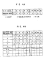
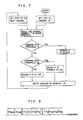
- An example of stored results is shown in Fig. 6A, and a flow chart illustrating the check procedure is shown in Fig. 7. The check procedure is always performed continuously while the base station does not communicate with a subscriber station.
- a plurality of transceivers are present in a base station as shown in Fig. 3, it is possible to known the idle or busy status of radio channels in short time by operating in paralle all the receivers which do not communicate with a subscriber station.
- the controller 1-7 causes the monitor result (control information) of a base station exemplarily shown in Fig. 6A to be sent to neighbouring base stations and causes the monitor results of neighbouring base stations to be received, respectively via the data exchange transceiver 1-5 and the communication lines 46 and 47 at predetermined time intervals or every time the idle or busy status changes.
- the memory 5-1 stores the monitor results including the idle or busy status monitored by its own base station and the idle or busy status monitored by neighbouring base stations, an example of which is shown in Fig. 6B.
- FIG. 6B illustrates the contents of the memory of the base station 1 wherein the base stations 2 to 4 are registered as neighbouring base stations of the base station 1. It is assumed here that the other base stations are remotely located from the base station 1 and give no influence upon channel allocation of the base station 1.
- the monitor results or control information data of channels have been described as being sent or received via the communication lines 46 and 47.
- the monitor results may be sent or received via a path of the data exchange transceiver 1-5, the line 1-8 and antenna 53 shown in Fig. 3 by using a radio channel dedicated to such data exchange.
- Fig. 8 shows one example of channel allocation wherein channels CH1 to CH50 are audio channels for telephone communication, channel CH CONT is a channel used for the control signals for a call initiation, a call reception, a hand-off and the like, and channel CH DATA is a channel used for the exchange of the control information data.
- control channel CH CONT may be used in common.
- a packet communication system with a well known CSMA carrier sense multiple access
- the control information data includes (1) an ID (identification) number of a base station, (2) a channel number whose channel is used in communication of a base station with a subscriber station, (3) a channel number whose channel is in use by another base station so that a base station concerned cannot use it due to the interference, (4) a signal strength of a subscriber station in case there is a transceiver unit communicating with the subscriber station, and (5) the degree of interference by which a radio channel is inhibited to be used.
- Each base station sends and receives the control information at constant intervals or every time the control information changes, to thereby attend to the status of neighbouring base stations.
- a signal strength is measured when the control information is received, an approximate distance to a neighbouring base station can be known based on the signal strength. It is apparent that the nearer the neighbouring base station is, the more a base station concerned receives the influence therefrom. Therefore, obviously the channel management can be effected more effectively if the received signal strength is used in weighting the control information data.
- the microcomputer unit 54 refers to the control information on its own base station and neighbouring base stations stored in the memory 1-6. Then, searched from the list of control information, selected is a radio channel which is vacant at its own base station and is in-use state, i.e., is impossible to use due to the co-channel interferer, at neighbouring base stations.
- radio channel No. 5 is selected since it is vacant at its base station and in-use state at two neighbouring base stations.
- the base station assigned a new radio channel causes the frequency synthesizer 59 to be set at the frequency of the assigned radio channel No. 5 to start communication with the subscriber station.
- the fact that the radio channel No. 5 has been occupied and now in use is declared to the neighbouring base stations via the controller 1-7.
- the declaration is constructed of digital signals in the form of packets including at least the ID number of the base station concerned and the channel number now in use.
- the neighbouring base stations receiving the declaration monitor the radio channel stated in the declaration and checks the received signal strength of the radio channel to accordingly update the control information. Therefore, if the base station assigned the new radio station collects the control information from the neighbouring base stations after a certain time lapse after starting the use of the radio channel, the base station can be informed of the influence of its radio wave upon the neighbouring base stations. Namely, it can dynamically identify those neighbouring base stations within its interference area. As a result, even if radio propagation characteristics change and the size and shape of interference area of each base station fluctuates, the base station concerned in the portable wireless communication systems can autonomically recognize the configuration of interference area.
- the microcomputer unit 513 causes the synthesizer 507 to set at a frequency of the common control channel (CH CONT ) and causes the call initiation signal to be modulated by the modem 514 to thereby transmit it via the audio signal modulator 509, frequency converter 510, band-pass filter 511, radio frequency amplifier 512, duplexer 502 and antenna 501.
- CH CONT common control channel
- the other base stations are monitoring the CH CONT through a vacant transceiver unit if they have such a vacant transceiver unit. Therefore, the call initiation signal is properly seized by a radio station having a vacant transceiver unit.
- the base stations seizing the call initiation, exchange data (call initiation response signal) regarding the seize status such as the strength of the call initiation signal. Based on the result of such exchange, each base station compares its seize status with those of neighbouring base stations and judges by itself if it should respond to the call initiation from the subscriber station. For a judgement criterion, the strength of a received call initiation signal is most suitable. However, other factors may be added in such judgement such judgement such as the number of vacant radio channels, the vacant status of transceiver units and the like. It is necessary however for all the base stations to follow the same criterion.
- the call initiation response signal Since the destination base stations to which the call initiation response signal is directed cannot be identified, the call initiation response signal is subjected to error correction coding and broadcast to all neighbouring base stations. Even if such procedure is adopted, only a single base station cannot always respond to the call initiation from the subscriber station due to such as transmission error.
- each base station judges that it should respond to the subscriber station, the former sends to the latter a call initiation acknowledge signal including the channel number to be used.
- the subscriber station receives call initiation acknowledge signals from a plurality of base stations, it is arranged such that the subscriber station returns a call initiation certificate signal to the base station which first responded to the call initiation signal. If alternatively there is no call initiation acknowledge signal from any base station, it is arranged such that the subscriber station sends again a call initiation signal.
- the subscriber station receiving the call initiation certificate signal moves to the radio channel designated by that signal.
- the base station sets the vacant transceiver unit at the designated channel and connects the subscriber station to the radio exchange.
- the radio exchange performs no operation but simply connects the private branch exchange 19 thereto.
- the procedure of sending a dial signal after the establishment of a communication line between the subscriber station and the radio station does not differ at all from the case of a conventional cordless telephone, so that the description therefor is omitted.
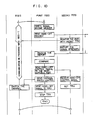
- a first base station now in communication with the subscriber station broadcasts a hand-off request signal to neighbouring base stations using a predetermined radio channel (refer to Fig. 10).
- the contents of a hand-off request signal include the channel number by which channel the communication with the subscriber station is in progress, the signal strength of the subscriber station, the ID number of the subscriber station and the like.
- a second base station receiving the hand-off request signal from the first base station monitors the subscriber station, checks the signal strength of the subscriber station and resultantly returns a hand-off response signal, by using a vacant transceiver unit if present in the second base station. Alternatively, of not present, the second base station may not respond or may return a signal reporting that it cannot respond. If the monitor result of the subscriber station by using a vacant transceiver unit leads to a judgement that the signal strength is not sufficient for communication, the hand-off response signal is also sent back.
- the first base station having broadcast the hand-off request signal compared hand-off response signals returned from neighbouring base stations, selects a base station which has seized a signal from the subscriber station at a strongest level, and sends a hand-off control signal thereto. At the same time, the first base station notifies the subscriber station to the effect that a hand-off will be performed, by using the radio channel now in use in communication with the subscriber station. Further, the first base station notifies the radio exchange the ID number of the base station to which communication is handed off, and requests the radio exchange to exchange lines. The hand-off is completed by the above-described procedure.
- PBX prepared in a PBX is a dedicated memory which stores the ID number of each base station near portable transceivers (subscriber stations) in the form of "location registration".
- location registration Upon a call reception, a portable transceiver of an objective subscriber station is called from the registered base station.
- each base station densely exchanges data regarding the use status of radio channels with neighbouring base stations so that each base station can autonomically perform channel management. Thus, it becomes unnecessary to install a base station supervising and managing the whole system. Further, each station can predict the degree of interference influencing other base stations while communicating with a subscriber station, thus resulting in efficient frequency allocation.
- each base station dynamicously manages the radio channels and service area, it becomes unnecessary to change the positional arrangement of base stations even in the indoor layout, where radio propagation characteristics or the like often changes.
Abstract
Description
- The present invention relates to portable wireless communication systems, and more particularly to portable wireless communication systems suitable for use in restricted area, e.g., indoor use in a building or the like.
- To further enhance mobile telephone systems for the purpose of obtaining a broader service area of wireless telephones, so-called indoor portable wireless communication systems have been widely studied which systems allow wireless telephones to be used indoors at buildings, underground streets, airports or the like.
- Different from the mobile telephone system, the characteristics of indoor portable wireless communication is available at any location within a total service area extending indoors at a building or on the premises of a factory, and that such communication is allowed to be conducted while a subscriber station is moving.
- With the progress of practical use of such wireless communication systems, it may well be expected that all indoor extensions are made cordless. Thus, terminal density of indoor portable wireless communi cation systems may become extensively higher than that of current mobile telephone systems.
- In view of the above-described background art, a technique of using the allocated radio frequency resources effectively and to the extremity has been desired. Therefore, it becomes necessary to use a small service area so that reuse efficiency of a same frequency can be improved.
- Technique required for such portable wireless communication systems are basically almost analogous to those required for conventional mobile telephone systems. However, the following channel allocation and hand-off techniques are different.
- One of the physical differences of indoor portable wireless communication systems from conventional mobile telephone systems is the total number of base stations. As discussed above, it becomes necessary for indoor portable wireless communication systems to install base stations at very small intervals, resulting in a very large total number of base stations.
- Therefore, it is difficult for a frequency management controller installed at the center of systems to control by itself the frequency management for all the base stations.
- In addition, the indoor radio propagation characteristics are often unknown. Even if they are known previously, it may be expected that they change to large extent due to a change of an indoor layout or the like. It is difficult accordingly to provide a fixed cell structure as seen in conventional mobile telephone systems, where base stations are installed systematically.
- To solve the above problems, a portable wireless communication system has been proposed as in Japanese Patent Laid-open Application JP-A-61-244137, which system performs "automatically" the management and allocation of radio frequencies or channels in such a manner that each of the base stations disposed at irregular intervals independently judges what channels are available, and determines a priority order in which the channels should be selected when used for communication with a subscriber station based on learning from the past history.
- The proposed portable wireless communication system, however, performs an autonomic processing only for the operation of channel allocation. Other technical factors required for the processings before the channel allocation, such as the call initiation from a subscriber station for determining the base station which is to be communicated with the subscriber station, the hand-off of the communication exchange according to movement of a subscriber station and the like, cannot be autonomically processed without a help of the control by an additionally installed management controller.
- It is a main object of the present invention to improve reuse efficiency of wireless frequency resources, i.e., to enable to use the same frequency channel as many as possible, in portable wireless communication systems used in restricted service areas.
- It is another object of the present invention to realize portable wireless communication systems in which when a base station thereof autonomically performs the management and allocation of radio channels, it independently performs the call initiation from a subscriber station for determining the base station which is to be communicated with the subscriber station and the hand-off of the communication exchange according to movement of a subscriber station.
- To achieve the above objects, the communication systems of this invention are constructed such that lines are provided among the base stations disposed at arbitrary intervals for exchanging beforehand control information on radio channel use status, use availability status and other internal status between each base station and its neighbouring base stations, and means is provided at each base station by which each base station autonomically performs the management of radio channels based on the exchange information.
- According to the portable wireless communication systems of this invention, since each base station has the control informations on neighbouring base stations, each base station can independently judges the concerned conditions for processing hand-off and call initiation from a subscriber station and performs following processings.
- The above-mentioned and other features and objects of this invention will become more apparent by reference to the following description taken in conjunction with the accompanying drawings.
-
- Fig. 1 is a schematic diagram showing the overall arrangement of portable wireless communication systems according to an embodiment of the present invention;
- Fig. 2 is a partially broken-out perspective view of a building used for explaining the indoor portable wireless communication systems;
- Fig. 3 shows an embodiment of a base station of the portable wireless communication systems of this invention;
- Fig. 4 shows an embodiment of a transceiver unit shown in Fig. 3;
- Fig. 5 shows an embodiment of the arrangement of a portable subscriber station or transceiver;
- Figs. 6A and 6B illustrate examples of control information according to the present invention;
- Fig. 7 is a flow chart illustrating the operation by a base station to obtain its control information;
- Fig. 8 shows radio channels used by a base station;
- Fig. 9 is a flow chart illustrating a "call initiation" process in the portable wireless communication system of this invention; and
- Fig. 10 is a flow chart illustrating a "hand-off" process in the portable wireless communication systems of this invention.
- Fig. 1 shows an embodiment of the arrangement of the portable wireless communication systems of this invention.
- The
base stations 1 to 8 are installed in respective rooms of abuilding 10 as shown in Fig. 2 and communicate at a radio intensity higher than a predetermined level in the service area 11 to 17, respectively. On the premises of a building or the like to which the present invention is principally applied, there are many materials such as walls, lockers and the like which absorb and reflect radio waves. Consequently, the shape of each service area 11 to 17 of the base station does not become an ideal circle but it takes three-dimensionally complicated configuration. In addition, it is common that the indoor layout is often changed so that the radio propagation characteristics and the shape of service areas change. - It is not practical to move any of the
base stations 1 to 7 every time the indoor layout is changed. In view of this, to prevent an out-of-service area from being produced by any possible slight layout change, it is necessary to dispose the base stations at higher density so that the service areas of the base stations should overlap each other considerablly. - Under such circumstances,
subscriber stations - Therefore, in the embodiment shown in Fig. 1,
communication lines 40 to 49 are mounted betweenbase stations 1 to 7 which have a possibility of interference therebetween. Each radio station exchanges control information on channel use status, use availability status and other internal status with other neighbouring base stations, and autonomically performs the management of radio channels based on the exchanged control information so as not to interfere with other niehgbouring base stations. - Each
base station 1 to 7 is connected to aradio exchange 18 viacommunication lines 31 to 37. Theradio exchange 18 is connected to awire exchange 19 for exchange withwire telephones 21 to 23 in the building, and further with wire telephones in other buildings viawires 20. - In this embodiment, the
base stations 1 to 7 autonomically perform the radio frequency channel allocation so that the radio exchange concerns no channel allocation but only the exchange operation. - The structure and operation of each element of the embodiment shown in Fig. 1 will be described in detail.
- Fig. 3 shows an embodiment of the structure of the
base station 1. Thebase station 1 includes transceiver units 1-1, 1-2, 1-3 and 1-4, a data exchange transceiver 1-5, a memory 1-6, a controller 1-7. There are as many transceiver units 1-1 to 1-4 as the number of subscriber stations which can be used at the same time within the service area of thebase station 1. The data exchange transceiver 1-5 is connected tolines subscriber stations antenna 53, and are connected via thecommunication line 31 to theradio exchange 18 and/or thewire exchange 10. - Fig. 4 shows one example of the structure of the transceiver unit provided in the base station. In the figure, the transceiver unit includes a
microprocessor unit 54, amodulator 55 for audio signals, afrequency converter 56 and ahigh frequency amplifier 57 whose output power may preferably be variable. The transceiver unit further includes aduplexer 58, afrequency synthesizer 59, areceiver amplifier 60, a frequency converter 61, a band-pass filter 62, ademodulator 63 for audio signals, anenvelope detector 64 for received signals which is provided for measuring signal strength and interference strength during communication, and amodem 65 for sending and receiving digital control signals to and from the associated subscriber station. - The transceiver unit as constructed above is almost similar to a conventional known one, as shown in, for example, "Lightweight Handheld Portable Cordless Telephone Set" by Kawasaki et al, NTT report of Research in Practical Use 1986, Vol. 35, No. 2, pages 191-197, so that the detailed description therefor is omitted.
- Fig. 5 is a block diagram showing an example of a subscriber station. In the figure, the subscriber station includes an
antenna 501, aduplexer 502, afrequency synthesizer 503, a band-pass filter 504, adetector 505, anaudio amplifier 506, afrequency synthesizer 507, amicrophone amplifier 508, amodulator 509, afrequency converter 510, a band-pass filter 511, aradio frequency amplifier 512, amicrocomputer unit 513, amodem 514 for digital signals, asound generator 515 such as a bell or a buzzer informing a call reception, abattery 516 for powering the subscriber station, a dial pad anddisplay section 517, amicrophone 518 and aloudspeaker 519. - The structure of the subscriber station is also the same as that of a conventionally known radio mobile station, as shown in, for example, "Cordless Telephone Equipment Meeting CEPT Standards" by Nishihara et al. NEC Res. & Develop., No. 82, July 1986, pages 104-109 so that the detailed description therefor is omitted.
- The main operations of the portable wireless communication systems of this invention, i.e., the radio channel management, the call initiation and the hand-off process will now be described.
- As discussed previously with Fig. 1, each
base station 1 to 7 sequentially monitors radio channels allotted to the system at a time interval during which it does not communicate with any of thesubscriber stations - First, the
microcomputer unit 54 shown in Fig. 3 determines a channel check order in accordance with a predetermined order, and causes thefrequency synthesizer 59 to set at the frequency of a radio channel in accordance with the channel check order. Thus, theamplifier 60 is allowed to receive the radio channel. Themicrocomputer unit 54 monitors an output from thereceiver 60 to read a signal strength of the radio channel and store it in the memory 1-6. In this case, the received signal strength is compared with signal strength threshold values to judge if the radio channel is in use because of there is interference from other channels, can be used because of negligible interference or is vacant because of no signal from other channels. The result is stored in the memory 1-6. An example of stored results is shown in Fig. 6A, and a flow chart illustrating the check procedure is shown in Fig. 7. The check procedure is always performed continuously while the base station does not communicate with a subscriber station. - If a plurality of transceivers are present in a base station as shown in Fig. 3, it is possible to known the idle or busy status of radio channels in short time by operating in paralle all the receivers which do not communicate with a subscriber station.
- Next, the controller 1-7 causes the monitor result (control information) of a base station exemplarily shown in Fig. 6A to be sent to neighbouring base stations and causes the monitor results of neighbouring base stations to be received, respectively via the data exchange transceiver 1-5 and the
communication lines - An example shown in Fig. 6B illustrates the contents of the memory of the
base station 1 wherein thebase stations 2 to 4 are registered as neighbouring base stations of thebase station 1. It is assumed here that the other base stations are remotely located from thebase station 1 and give no influence upon channel allocation of thebase station 1. - In the above-described embodiment, the monitor results or control information data of channels have been described as being sent or received via the
communication lines antenna 53 shown in Fig. 3 by using a radio channel dedicated to such data exchange. - Fig. 8 shows one example of channel allocation wherein channels CH₁ to CH₅₀ are audio channels for telephone communication, channel CHCONT is a channel used for the control signals for a call initiation, a call reception, a hand-off and the like, and channel CHDATA is a channel used for the exchange of the control information data.
- As a channel for exchanging the control information data, the control channel CHCONT may be used in common.
- Since a plurality of base stations use the same frequency of the control information data exchange channel CHDATA, a packet communication system with a well known CSMA (carrier sense multiple access) is preferable to be used for such data transfer.
- As described previously, the control information data includes (1) an ID (identification) number of a base station, (2) a channel number whose channel is used in communication of a base station with a subscriber station, (3) a channel number whose channel is in use by another base station so that a base station concerned cannot use it due to the interference, (4) a signal strength of a subscriber station in case there is a transceiver unit communicating with the subscriber station, and (5) the degree of interference by which a radio channel is inhibited to be used.
- Each base station sends and receives the control information at constant intervals or every time the control information changes, to thereby attend to the status of neighbouring base stations. In this case, if a signal strength is measured when the control information is received, an approximate distance to a neighbouring base station can be known based on the signal strength. It is apparent that the nearer the neighbouring base station is, the more a base station concerned receives the influence therefrom. Therefore, obviously the channel management can be effected more effectively if the received signal strength is used in weighting the control information data.
- Next, the channel allocation scheme by a base station based on the control information will be described. When an additional radio channel becomes necessary for a base station to start communication with a subscriber station, e.g., when a base station receives a call request from a subscriber station, first the
microcomputer unit 54 refers to the control information on its own base station and neighbouring base stations stored in the memory 1-6. Then, searched from the list of control information, selected is a radio channel which is vacant at its own base station and is in-use state, i.e., is impossible to use due to the co-channel interferer, at neighbouring base stations. If there are a plurality of radio channels meeting such conditions, selected is a radio channel which is vacant at its own base station and is in-use state at as many neighbouring base stations as possible. In the example shown in Fig. 6B, the radio channel No. 5 is selected since it is vacant at its base station and in-use state at two neighbouring base stations. - Following the above procedure, the base station assigned a new radio channel causes the
frequency synthesizer 59 to be set at the frequency of the assigned radio channel No. 5 to start communication with the subscriber station. At the same time, the fact that the radio channel No. 5 has been occupied and now in use is declared to the neighbouring base stations via the controller 1-7. The declaration is constructed of digital signals in the form of packets including at least the ID number of the base station concerned and the channel number now in use. - The neighbouring base stations receiving the declaration monitor the radio channel stated in the declaration and checks the received signal strength of the radio channel to accordingly update the control information. Therefore, if the base station assigned the new radio station collects the control information from the neighbouring base stations after a certain time lapse after starting the use of the radio channel, the base station can be informed of the influence of its radio wave upon the neighbouring base stations. Namely, it can dynamically identify those neighbouring base stations within its interference area. As a result, even if radio propagation characteristics change and the size and shape of interference area of each base station fluctuates, the base station concerned in the portable wireless communication systems can autonomically recognize the configuration of interference area.
- Next, the operation procedure of this embodiment will be described definitely, taking particularly the operations of call initiation and hand-off of a subscriber station as examples.
- When an owner of a subscriber station sends a call initiation from the
dial pad 517, themicrocomputer unit 513 causes thesynthesizer 507 to set at a frequency of the common control channel (CHCONT) and causes the call initiation signal to be modulated by themodem 514 to thereby transmit it via theaudio signal modulator 509,frequency converter 510, band-pass filter 511,radio frequency amplifier 512,duplexer 502 andantenna 501. - Referring to Fig. 9, the other base stations are monitoring the CHCONT through a vacant transceiver unit if they have such a vacant transceiver unit. Therefore, the call initiation signal is properly seized by a radio station having a vacant transceiver unit.
- However, as described previously, there are many overlapped service areas of the base stations so that the call initiation signal may be seized by plural base stations. It is obvious that plural base stations cannot be allowed to respond to the call initiation signal at the same time. In this connection, the base stations seizing the call initiation, exchange data (call initiation response signal) regarding the seize status such as the strength of the call initiation signal. Based on the result of such exchange, each base station compares its seize status with those of neighbouring base stations and judges by itself if it should respond to the call initiation from the subscriber station. For a judgement criterion, the strength of a received call initiation signal is most suitable. However, other factors may be added in such judgement such as the number of vacant radio channels, the vacant status of transceiver units and the like. It is necessary however for all the base stations to follow the same criterion.
- Since the destination base stations to which the call initiation response signal is directed cannot be identified, the call initiation response signal is subjected to error correction coding and broadcast to all neighbouring base stations. Even if such procedure is adopted, only a single base station cannot always respond to the call initiation from the subscriber station due to such as transmission error.
- In view of this, when each base station judges that it should respond to the subscriber station, the former sends to the latter a call initiation acknowledge signal including the channel number to be used. For the case where the subscriber station receives call initiation acknowledge signals from a plurality of base stations, it is arranged such that the subscriber station returns a call initiation certificate signal to the base station which first responded to the call initiation signal. If alternatively there is no call initiation acknowledge signal from any base station, it is arranged such that the subscriber station sends again a call initiation signal.
- Next, the subscriber station receiving the call initiation certificate signal moves to the radio channel designated by that signal. The base station sets the vacant transceiver unit at the designated channel and connects the subscriber station to the radio exchange.
- At the time when a call initiation is established, the radio exchange performs no operation but simply connects the
private branch exchange 19 thereto. The procedure of sending a dial signal after the establishment of a communication line between the subscriber station and the radio station does not differ at all from the case of a conventional cordless telephone, so that the description therefor is omitted. - After starting communication between the subscriber station and the base station in accordance with the above-described procedure, it may happen that the location of the subscriber station moves out of the service area of the base station concerned. In this connection, the base station always monitors the signal strength of the subscriber station and, when the signal strength lowers, it requests another neighbouring base station to relay the subscriber station. To this end, a first base station now in communication with the subscriber station broadcasts a hand-off request signal to neighbouring base stations using a predetermined radio channel (refer to Fig. 10). The contents of a hand-off request signal include the channel number by which channel the communication with the subscriber station is in progress, the signal strength of the subscriber station, the ID number of the subscriber station and the like.
- A second base station receiving the hand-off request signal from the first base station monitors the subscriber station, checks the signal strength of the subscriber station and resultantly returns a hand-off response signal, by using a vacant transceiver unit if present in the second base station. Alternatively, of not present, the second base station may not respond or may return a signal reporting that it cannot respond. If the monitor result of the subscriber station by using a vacant transceiver unit leads to a judgement that the signal strength is not sufficient for communication, the hand-off response signal is also sent back.
- The first base station having broadcast the hand-off request signal compared hand-off response signals returned from neighbouring base stations, selects a base station which has seized a signal from the subscriber station at a strongest level, and sends a hand-off control signal thereto. At the same time, the first base station notifies the subscriber station to the effect that a hand-off will be performed, by using the radio channel now in use in communication with the subscriber station. Further, the first base station notifies the radio exchange the ID number of the base station to which communication is handed off, and requests the radio exchange to exchange lines. The hand-off is completed by the above-described procedure.
- The above description has been directed to a call initiation, management of radio channels and hand-off. For the call reception procedure although not described, a conventional known system, as shown in, for example, "Improved Cordless Telephone Set" by Kato et al, NTT Equipment, December 1985, pages 102-108, may be used.
- Namely, prepared in a PBX is a dedicated memory which stores the ID number of each base station near portable transceivers (subscriber stations) in the form of "location registration". Upon a call reception, a portable transceiver of an objective subscriber station is called from the registered base station.
- As described so far, each base station densely exchanges data regarding the use status of radio channels with neighbouring base stations so that each base station can autonomically perform channel management. Thus, it becomes unnecessary to install a base station supervising and managing the whole system. Further, each station can predict the degree of interference influencing other base stations while communicating with a subscriber station, thus resulting in efficient frequency allocation.
- Furthermore, since each base station dynamiclly manages the radio channels and service area, it becomes unnecessary to change the positional arrangement of base stations even in the indoor layout, where radio propagation characteristics or the like often changes.
Claims (12)
a plurality of base stations (1-7) each covering a predetermined area (11-17);
a subscriber station (51, 52) movable within said predetermined area which can communicate with said base station via radio propagation; and
a dedicated line (40-49) provided between adjacent base stations of said plurality of base stations for exchanging control information on channel use;
wherein said base station comprises means (1-6) for storing and control information on its own base station and other base stations to be obtained from said dedicated line and means (1-7) for selecting a radio channel and a radio station by and with which said subscriber station performs communication, in accordance with said control information in said storage means.
an identifier number of its own base station;
a channel number which channel is presently used by its own base station in communicating with said subscriber station, among a plurality of radio channels assigned for the communication between said own base station and said subscriber station; and
a channel number which channel is used by another base station and cannot be used by said own base station due to the interference, among said plurality of assigned radio channels.
a radio exchange (18) connected to said plurality of base stations; and
a private branch exchange (19) connected to said radio exchange and a wire telephone present in said predetermined area.
while each base station of said plurality of base stations does not communicate with said subscriber station, a first step of checking the idle or busy status of radio channels of its own base station to obtain control information;
a second step of exchanging said control information obtained at the first step with neighbouring base stations via a dedicated line (40-49);
when said portable radio transceiver sends a call initiation signal via a particular radio channel, a third step in which said base station receiving said call initiation signal independently refers to said control information to allocate a base station and a radio channel with and by which said portable radio transceiver performs communication; and
a fourth step of performing communication between said portable radio transceiver and said base station via said radio channel allocated at said third step.
a step in which said base station receiving said call initiation signal sends to said neighbouring base stations a call initiation response signal to the effect that said base station has seized said call initiation signal from said portable radio transceiver; and
a step in which said base radio station receiving said call initiation response signal refers to said call initiation response signals of its own base station and neighbouring base stations and judges if said own base station should respond to said call initiation signal.
when the signal strength of said portable radio transceiver lowers to the extent that it becomes necessary to hand off communication with one base station, a step of sending to one or more neighbouring base stations a hand-off request signal including an identifier number and signal strength of said portable radio transceiver and the channel number in use for the communication;
a step wherein said neighbouring base stations receiving said hand-off request signal monitor the signal from said portable radio transceiver and return to said one base station a hand-off response signal including the monitor result and other information; and
a step wherein said one base station receiving said hand-off response signals from said neighbouring base stations compares data sent from said neighbouring base stations, and sends a hand-off control signal asking for a hand-off of communication to a most suitable base station in accordance with a predetermined comparison criterion.
when one of said neighbouring base stations returns said hand-off response signal after said one base station sent said hand-off request signal, a step wherein the communication by said portable radio transceiver with said one base station is maintained to continue and after a predetermined time lapse, said one base station sends again said hand-off request signal.
Applications Claiming Priority (4)
| Application Number | Priority Date | Filing Date | Title |
|---|---|---|---|
| JP62063784A JP2641441B2 (en) | 1987-03-20 | 1987-03-20 | Mobile radio communication method and mobile radio communication system |
| JP63784/87 | 1987-03-20 | ||
| JP279199/87 | 1987-11-06 | ||
| JP62279199A JP2602251B2 (en) | 1987-11-06 | 1987-11-06 | Mobile radio communication method and radio base station |
Publications (3)
| Publication Number | Publication Date |
|---|---|
| EP0283683A2 true EP0283683A2 (en) | 1988-09-28 |
| EP0283683A3 EP0283683A3 (en) | 1989-07-19 |
| EP0283683B1 EP0283683B1 (en) | 1994-01-12 |
Family
ID=26404910
Family Applications (1)
| Application Number | Title | Priority Date | Filing Date |
|---|---|---|---|
| EP88101646A Expired - Lifetime EP0283683B1 (en) | 1987-03-20 | 1988-02-04 | Portable wireless communication systems and method |
Country Status (3)
| Country | Link |
|---|---|
| US (1) | US4881271A (en) |
| EP (1) | EP0283683B1 (en) |
| DE (1) | DE3886967T2 (en) |
Cited By (23)
| Publication number | Priority date | Publication date | Assignee | Title |
|---|---|---|---|---|
| EP0326104A2 (en) * | 1988-01-25 | 1989-08-02 | Fujitsu Limited | Channel changing system |
| WO1991009474A1 (en) * | 1989-12-19 | 1991-06-27 | Northern Telecom Limited | Adjacent and co-channel interference avoidance |
| WO1991018484A1 (en) * | 1990-05-11 | 1991-11-28 | Tateco Ab | Installation for connection of cordless telephone sets to a subscriber's telephone exchange |
| EP0467600A1 (en) * | 1990-07-17 | 1992-01-22 | Nortel Networks Corporation | Radio link architecture for wireless communication systems |
| EP0483550A2 (en) * | 1990-10-29 | 1992-05-06 | International Business Machines Corporation | Coordination of wireless medium access among a plurality of base stations |
| EP0488173A2 (en) * | 1990-11-27 | 1992-06-03 | Canon Kabushiki Kaisha | Wireless communication channel selecting method |
| EP0488976A2 (en) * | 1990-11-28 | 1992-06-03 | Telefonaktiebolaget L M Ericsson | Multiple access handling in a cellular communication system |
| EP0492800A2 (en) * | 1990-12-05 | 1992-07-01 | Nortel Networks Corporation | Improved inter-cell call hand-over in radio communication systems with dynamic channel allocation |
| EP0639036A2 (en) * | 1993-08-12 | 1995-02-15 | MacNamee, Robert Joseph Gerard | Cordless telephone handover system |
| EP0647077A2 (en) * | 1993-09-30 | 1995-04-05 | International Business Machines Corporation | Method for controlling a mobile integrated voice and data (IVD) system having a plurality of personal station (PS'S) |
| EP0654952A2 (en) * | 1993-11-23 | 1995-05-24 | AT&T Corp. | Method and apparatus for dynamic channel allocation for wireless communication |
| EP0802691A2 (en) * | 1996-04-18 | 1997-10-22 | Nec Corporation | Network system for mobile radio communication |
| WO1998000997A2 (en) * | 1996-06-28 | 1998-01-08 | Harris Corporation | Improvements to or relating to a multiple use wireless communications system and method having dynamic reallocation of communication frequencies |
| WO1998000992A2 (en) * | 1996-06-28 | 1998-01-08 | Harris Corporation | Improvements in or relating to a method and apparatus for determining symbol timing in a wireless communications system, also using a reusable control channel, and reducing power |
| US5887255A (en) * | 1996-06-28 | 1999-03-23 | Marris Corporation | Multiple use wireless communications system and method |
| US5943325A (en) * | 1996-06-28 | 1999-08-24 | Ctp Systems, Ltd. | Method and apparatus for determining symbol timing in a wireless communications system |
| US6023460A (en) * | 1996-06-28 | 2000-02-08 | Harris Corporation | Wireless communications system and method using a reusable control channel |
| EP1089586A2 (en) * | 1999-09-28 | 2001-04-04 | Siemens Information and Communication Networks, Inc. | Dynamic networking between mobile stations in wireless networks |
| CN1074231C (en) * | 1995-03-03 | 2001-10-31 | 株式会社日立制作所 | Radio communication system |
| WO2004049631A1 (en) * | 2002-11-22 | 2004-06-10 | Koninklijke Philips Electronics N.V. | Robust communication system |
| EP2296305A3 (en) * | 2000-10-10 | 2013-11-06 | Adaptix, Inc. | Channel assignment in an OFDMA system |
| US8738020B2 (en) | 2000-12-15 | 2014-05-27 | Adaptix, Inc. | Multi-carrier communications with adaptive cluster configuration and switching |
| US8760992B2 (en) | 2004-12-07 | 2014-06-24 | Adaptix, Inc. | Method and system for switching antenna and channel assignments in broadband wireless networks |
Families Citing this family (97)
| Publication number | Priority date | Publication date | Assignee | Title |
|---|---|---|---|---|
| US5375161A (en) | 1984-09-14 | 1994-12-20 | Accessline Technologies, Inc. | Telephone control system with branch routing |
| US5752191A (en) | 1984-09-14 | 1998-05-12 | Accessline Technologies, Inc. | Telephone control system which connects a caller with a subscriber AT A telephone address |
| US6545589B1 (en) | 1984-09-14 | 2003-04-08 | Aspect Communications Corporation | Method and apparatus for managing telecommunications |
| US6201950B1 (en) | 1984-09-14 | 2001-03-13 | Aspect Telecommunications Corporation | Computer-controlled paging and telephone communication system and method |
| US5588037A (en) | 1984-09-14 | 1996-12-24 | Accessline Technologies, Inc. | Remote access telephone control system |
| US5673031A (en) * | 1988-08-04 | 1997-09-30 | Norand Corporation | Redundant radio frequency network having a roaming terminal communication protocol |
| US5195127A (en) * | 1988-09-19 | 1993-03-16 | Kabushiki Kaisha Toshiba | Radio telephone system and its control method |
| DE3843565A1 (en) * | 1988-12-23 | 1990-06-28 | Standard Elektrik Lorenz Ag | RADIO TELEPHONE SYSTEM IN THE FORM OF A PABX |
| JPH02312492A (en) * | 1989-05-29 | 1990-12-27 | Nec Corp | Channel assignment method in mobile communication system and learning system for base station arrangement information |
| US5701297A (en) * | 1989-09-27 | 1997-12-23 | Motorola, Inc. | Data over cellular |
| US5495482A (en) * | 1989-09-29 | 1996-02-27 | Motorola Inc. | Packet transmission system and method utilizing both a data bus and dedicated control lines |
| US5477541A (en) * | 1989-09-29 | 1995-12-19 | White; Richard E. | Addressing technique for storing and referencing packet data |
| US5093927A (en) * | 1989-10-20 | 1992-03-03 | Motorola, Inc. | Two-way communication system |
| JPH048046A (en) * | 1990-04-26 | 1992-01-13 | Fujitsu Ltd | Method and apparatus for idle channel retrieval in system cordless telephone set |
| ES2117638T3 (en) * | 1990-04-27 | 1998-08-16 | Ericsson Telefon Ab L M | DEVICE AND METHOD FOR DIRECTING CALLS TO MOBILE PHONE SUBSCRIBERS. |
| US5153902A (en) * | 1990-04-27 | 1992-10-06 | Telefonaktiebolaget L M Ericsson | Multi-exchange paging system for locating a mobile telephone in a wide area telephone network |
| SE466374B (en) * | 1990-06-25 | 1992-02-03 | Ericsson Telefon Ab L M | MOBILE SYSTEMS |
| US5355516A (en) * | 1990-09-28 | 1994-10-11 | Motorola, Inc. | Method for reducing superfluous channel allocation in a cellular radiotelephone communication system |
| CA2050104C (en) | 1990-10-01 | 1995-10-03 | Noach Amitay | Distributed switching cellular communication system |
| US5371780A (en) * | 1990-10-01 | 1994-12-06 | At&T Corp. | Communications resource assignment in a wireless telecommunications system |
| US5384826A (en) * | 1990-10-01 | 1995-01-24 | At&T Bell Laboratories | Distributed packetized switching cellular radio telephone communication system with handoff |
| CA2052466C (en) * | 1990-10-02 | 2001-05-08 | Masayuki Sakamoto | Method of handover and route diversity in mobile radio communication |
| US5239673A (en) * | 1990-10-29 | 1993-08-24 | International Business Machines Corporation | Scheduling methods for efficient frequency reuse in a multi-cell wireless network served by a wired local area network |
| JP2500963B2 (en) | 1990-10-29 | 1996-05-29 | インターナショナル・ビジネス・マシーンズ・コーポレイション | Two-way information communication method |
| US5212806A (en) * | 1990-10-29 | 1993-05-18 | International Business Machines Corporation | Distributed control methods for management of migrating data stations in a wireless communications network |
| US5274841A (en) * | 1990-10-29 | 1993-12-28 | International Business Machines Corporation | Methods for polling mobile users in a multiple cell wireless network |
| US5265150A (en) * | 1991-01-30 | 1993-11-23 | At&T Bell Laboratories | Automatically configuring wireless PBX system |
| JP2653000B2 (en) * | 1991-04-24 | 1997-09-10 | 日本電気株式会社 | Mobile wireless communication system |
| US6714559B1 (en) * | 1991-12-04 | 2004-03-30 | Broadcom Corporation | Redundant radio frequency network having a roaming terminal communication protocol |
| EP0610209A1 (en) * | 1991-05-17 | 1994-08-17 | Motorola, Inc. | Channel acquisition method and apparatus for a communication system |
| CA2043127C (en) * | 1991-05-23 | 1996-05-07 | Martin Handforth | Wireless communication zone management system |
| WO1993000750A1 (en) * | 1991-06-25 | 1993-01-07 | Motorola, Inc. | Method and apparatus for establishing a communication link |
| US5335360A (en) * | 1991-06-25 | 1994-08-02 | Motorola, Inc. | Base site selection apparatus and method |
| JPH06508970A (en) * | 1991-07-01 | 1994-10-06 | モトローラ・インコーポレイテッド | Personal communication system providing auxiliary information mode |
| JPH0530025A (en) * | 1991-07-25 | 1993-02-05 | Canon Inc | Cordless telephone system |
| SE468965B (en) * | 1991-08-30 | 1993-04-19 | Ericsson Telefon Ab L M | COMBINED MOBILE RADIO SYSTEM |
| US6407991B1 (en) | 1993-05-06 | 2002-06-18 | Intermec Ip Corp. | Communication network providing wireless and hard-wired dynamic routing |
| NL9102047A (en) * | 1991-12-09 | 1993-07-01 | Nederland Ptt | METHOD FOR TRANSMITTING BETWEEN CENTRALS THE TREATMENT OF AN ACTIVE LINK BETWEEN A USER ON THE ONE PART AND A MOBILE TERMINAL ON THE OTHER. |
| US5353331A (en) * | 1992-03-05 | 1994-10-04 | Bell Atlantic Network Services, Inc. | Personal communications service using wireline/wireless integration |
| US5343512A (en) * | 1992-03-27 | 1994-08-30 | Motorola, Inc. | Call setup method for use with a network having mobile end users |
| WO1993020642A1 (en) * | 1992-04-03 | 1993-10-14 | Motorola Inc. | Apparatus and method for servicing wireless subscribers in a wireline environment |
| US5448619A (en) * | 1992-04-14 | 1995-09-05 | Orion Industries, Inc. | Apparatus and a method of allowing private cellular operation within an existing public cellular system |
| US5448750A (en) * | 1992-04-22 | 1995-09-05 | Telefonaktiebolaget Lm Ericsson | Segregation method of dynamic channel allocation in a mobile radio system |
| US5410737A (en) * | 1992-04-27 | 1995-04-25 | American Pcs L.P. | Frequency agile sharing technology (FAST) for a personal communications service system |
| US5752164A (en) * | 1992-04-27 | 1998-05-12 | American Pcs L.P. | Autonomous remote measurement unit for a personal communications service system |
| US5315637A (en) * | 1992-05-01 | 1994-05-24 | Motorola, Inc. | Apparatus and method for controlling the routing of incoming calls in a wireless communication system |
| EP0582373B1 (en) * | 1992-07-17 | 1999-10-06 | Sun Microsystems, Inc. | Method and apparatus for implementing self-organization in a wireless local area network |
| US5285443A (en) * | 1992-08-25 | 1994-02-08 | Motorola, Inc. | Method and apparatus for synchronizing a time division duplexing communication system |
| DE69332431T2 (en) * | 1992-09-08 | 2003-06-18 | Sun Microsystems Inc | Method and device for maintaining connection possibilities of nodes in a wireless local area network |
| CA2107820A1 (en) * | 1992-10-16 | 1994-04-17 | Keith Daniel O'neill | Low-power wireless system for telephone services |
| FI96156C (en) * | 1992-11-18 | 1996-05-10 | Nokia Telecommunications Oy | Method and system for establishing a telecommunication connection for telecommunication devices located in a restricted calling area |
| JP2878052B2 (en) * | 1993-01-12 | 1999-04-05 | 日本電気通信システム株式会社 | Electric field level measurement area control method |
| US5463673A (en) * | 1993-04-29 | 1995-10-31 | Northern Telecom Limited | In-building radio deployment technique for wireless personal communications systems |
| US5457680A (en) * | 1993-05-18 | 1995-10-10 | International Business Machines Corporation | Data gateway for mobile data radio terminals in a data communication network |
| DE4495338T1 (en) * | 1993-07-20 | 1995-10-19 | Motorola Inc | Circuit and method for operating a wireless communication system |
| DE4330704A1 (en) * | 1993-09-10 | 1995-03-16 | Sel Alcatel Ag | Telepoint system |
| US5724665A (en) * | 1993-11-24 | 1998-03-03 | Lucent Technologies Inc. | Wireless communication base station |
| WO1995023487A1 (en) | 1994-02-24 | 1995-08-31 | Gte Mobile Communications Service Corporation | Cellular radiotelephone system with remotely programmed mobile stations |
| US5594782A (en) * | 1994-02-24 | 1997-01-14 | Gte Mobile Communications Service Corporation | Multiple mode personal wireless communications system |
| US6453178B1 (en) | 1994-02-24 | 2002-09-17 | Gte Wireless Service Corporation | Radiotelephone operating method with connected NPA dialing analysis |
| DK0746953T3 (en) | 1994-02-24 | 2004-07-26 | Gte Wireless Service Corp | Cellular radio telephone with call number analysis |
| US6026156A (en) | 1994-03-18 | 2000-02-15 | Aspect Telecommunications Corporation | Enhanced call waiting |
| US5694546A (en) | 1994-05-31 | 1997-12-02 | Reisman; Richard R. | System for automatic unattended electronic information transport between a server and a client by a vendor provided transport software with a manifest list |
| US5537459A (en) * | 1994-06-17 | 1996-07-16 | Price; Evelyn C. | Multilevel cellular communication system for hospitals |
| AU2864995A (en) * | 1994-06-17 | 1996-01-15 | Evelyn C. Price | Multilevel wireless communication system for hospitals |
| CA2153516C (en) * | 1994-07-20 | 1999-06-01 | Yasuo Ohgoshi | Mobile station for cdma mobile communication system and detection method of the same |
| JP2626597B2 (en) * | 1994-12-14 | 1997-07-02 | 日本電気株式会社 | Radio base station selection method in cellular mobile radio communication system |
| US5930727A (en) * | 1995-07-21 | 1999-07-27 | Ericsson Inc. | Analog fax and modem requests in a D-AMPS multi-line terminal system |
| US6411682B1 (en) | 1995-09-21 | 2002-06-25 | Aspect Telecommunications Corporation | Computer controlled paging and telephone communication system and method |
| US5883884A (en) * | 1996-04-22 | 1999-03-16 | Roger F. Atkinson | Wireless digital communication system having hierarchical wireless repeaters with autonomous hand-off |
| US6021122A (en) * | 1996-06-07 | 2000-02-01 | Qualcomm Incorporated | Method and apparatus for performing idle handoff in a multiple access communication system |
| US6131031A (en) * | 1997-10-10 | 2000-10-10 | Watkins- Johnson Company | System and method for an underlay cellular system |
| JPH11155165A (en) * | 1997-11-21 | 1999-06-08 | Toshiba Corp | Mobile communication system, base station equipment, and control station system |
| US6327469B1 (en) | 1998-12-11 | 2001-12-04 | Motorola, Inc. | Channel scanning method and apparatus |
| JP3349477B2 (en) * | 1999-09-08 | 2002-11-25 | 三洋電機株式会社 | Mobile communication device, mobile communication system, and communication channel assignment request method |
| US6845087B1 (en) | 1999-09-20 | 2005-01-18 | Northrop Grumman Corporation | Wideband wireless communications architecture |
| US7146176B2 (en) | 2000-06-13 | 2006-12-05 | Shared Spectrum Company | System and method for reuse of communications spectrum for fixed and mobile applications with efficient method to mitigate interference |
| JP3816334B2 (en) * | 2000-12-22 | 2006-08-30 | 株式会社エヌ・ティ・ティ・ドコモ | Radio resource allocation method and base station |
| US7047405B2 (en) * | 2001-04-05 | 2006-05-16 | Qualcomm, Inc. | Method and apparatus for providing secure processing and data storage for a wireless communication device |
| US10489449B2 (en) | 2002-05-23 | 2019-11-26 | Gula Consulting Limited Liability Company | Computer accepting voice input and/or generating audible output |
| US8611919B2 (en) | 2002-05-23 | 2013-12-17 | Wounder Gmbh., Llc | System, method, and computer program product for providing location based services and mobile e-commerce |
| US7409010B2 (en) | 2003-06-10 | 2008-08-05 | Shared Spectrum Company | Method and system for transmitting signals with reduced spurious emissions |
| WO2005027276A1 (en) * | 2003-09-15 | 2005-03-24 | Corning Cabelcon A/S | Coaxial angle connector |
| JP4479307B2 (en) * | 2004-03-30 | 2010-06-09 | 日本電気株式会社 | Wireless communication terminal and method for establishing wireless communication early |
| CN101019453B (en) * | 2004-09-10 | 2010-06-16 | 三菱电机株式会社 | Cross-zone handover method in wireless access network |
| JP4751759B2 (en) * | 2006-04-21 | 2011-08-17 | 株式会社エヌ・ティ・ティ・ドコモ | Base station and communication method |
| US9538388B2 (en) | 2006-05-12 | 2017-01-03 | Shared Spectrum Company | Method and system for dynamic spectrum access |
| US7564816B2 (en) | 2006-05-12 | 2009-07-21 | Shared Spectrum Company | Method and system for determining spectrum availability within a network |
| US8997170B2 (en) | 2006-12-29 | 2015-03-31 | Shared Spectrum Company | Method and device for policy-based control of radio |
| US8155649B2 (en) | 2006-05-12 | 2012-04-10 | Shared Spectrum Company | Method and system for classifying communication signals in a dynamic spectrum access system |
| US8055204B2 (en) | 2007-08-15 | 2011-11-08 | Shared Spectrum Company | Methods for detecting and classifying signals transmitted over a radio frequency spectrum |
| US8184653B2 (en) | 2007-08-15 | 2012-05-22 | Shared Spectrum Company | Systems and methods for a cognitive radio having adaptable characteristics |
| US8326313B2 (en) | 2006-05-12 | 2012-12-04 | Shared Spectrum Company | Method and system for dynamic spectrum access using detection periods |
| US8027249B2 (en) | 2006-10-18 | 2011-09-27 | Shared Spectrum Company | Methods for using a detector to monitor and detect channel occupancy |
| US20080004021A1 (en) * | 2006-06-30 | 2008-01-03 | Sanjay Addicam V | Seamless base station / set top box handoff |
| KR20080064699A (en) * | 2007-01-05 | 2008-07-09 | 삼성전자주식회사 | Network devices having handover information and method of exchanging handover information between the devices |
| EP2319260A2 (en) | 2008-08-19 | 2011-05-11 | Shared Spectrum Company | Method and system for dynamic spectrum access using specialty detectors and improved networking |
Citations (4)
| Publication number | Priority date | Publication date | Assignee | Title |
|---|---|---|---|---|
| US3764915A (en) * | 1971-06-25 | 1973-10-09 | Bell Telephone Labor Inc | Dynamic program control for channel assignment in mobile communication systems |
| US4163121A (en) * | 1976-08-30 | 1979-07-31 | Nippon Telegraph And Telephone Public Corporation | Radio channel control system for mobile radio telephone systems |
| WO1984000654A1 (en) * | 1982-08-03 | 1984-02-16 | Motorola Inc | Method and apparatus for assigning duplex radio channels and scanning duplex radio channels assigned to mobile and portable radiotelephones in a cellular radiotelephone communications system |
| EP0126557A1 (en) * | 1983-05-05 | 1984-11-28 | AT&T Corp. | High density cellular mobile radio communications |
Family Cites Families (6)
| Publication number | Priority date | Publication date | Assignee | Title |
|---|---|---|---|---|
| US3955140A (en) * | 1975-05-20 | 1976-05-04 | Public Systems, Inc. | Mobile radio extension unit with punch through operation |
| DE2805420A1 (en) * | 1978-02-09 | 1979-08-16 | Bosch Gmbh Robert | RADIO SYSTEM FOR TRANSMISSION OF MESSAGES |
| US4284848A (en) * | 1979-08-01 | 1981-08-18 | Frost Edward G | Switched network telephone subscriber distribution system |
| US4726014A (en) * | 1983-01-11 | 1988-02-16 | U.S. Holding Company, Inc. | Cellular mobile radio service telephone system |
| SE458734B (en) * | 1984-10-31 | 1989-04-24 | Ericsson Telefon Ab L M | PROCEDURE TO PROVIDE THE NUMBER OF CALL OPPORTUNITIES IN A MOBILE PHONE SYSTEM |
| JPH0659039B2 (en) * | 1985-04-22 | 1994-08-03 | 日本電気株式会社 | Wireless communication system |
-
1988
- 1988-02-04 EP EP88101646A patent/EP0283683B1/en not_active Expired - Lifetime
- 1988-02-04 DE DE3886967T patent/DE3886967T2/en not_active Expired - Fee Related
- 1988-02-09 US US07/153,906 patent/US4881271A/en not_active Expired - Lifetime
Patent Citations (4)
| Publication number | Priority date | Publication date | Assignee | Title |
|---|---|---|---|---|
| US3764915A (en) * | 1971-06-25 | 1973-10-09 | Bell Telephone Labor Inc | Dynamic program control for channel assignment in mobile communication systems |
| US4163121A (en) * | 1976-08-30 | 1979-07-31 | Nippon Telegraph And Telephone Public Corporation | Radio channel control system for mobile radio telephone systems |
| WO1984000654A1 (en) * | 1982-08-03 | 1984-02-16 | Motorola Inc | Method and apparatus for assigning duplex radio channels and scanning duplex radio channels assigned to mobile and portable radiotelephones in a cellular radiotelephone communications system |
| EP0126557A1 (en) * | 1983-05-05 | 1984-11-28 | AT&T Corp. | High density cellular mobile radio communications |
Cited By (56)
| Publication number | Priority date | Publication date | Assignee | Title |
|---|---|---|---|---|
| EP0326104A3 (en) * | 1988-01-25 | 1990-10-17 | Fujitsu Limited | Channel changing system |
| EP0326104A2 (en) * | 1988-01-25 | 1989-08-02 | Fujitsu Limited | Channel changing system |
| WO1991009474A1 (en) * | 1989-12-19 | 1991-06-27 | Northern Telecom Limited | Adjacent and co-channel interference avoidance |
| AU641444B2 (en) * | 1989-12-19 | 1993-09-23 | Northern Telecom Limited | Adjacent and co-channel interference avoidance |
| WO1991018484A1 (en) * | 1990-05-11 | 1991-11-28 | Tateco Ab | Installation for connection of cordless telephone sets to a subscriber's telephone exchange |
| EP0467600A1 (en) * | 1990-07-17 | 1992-01-22 | Nortel Networks Corporation | Radio link architecture for wireless communication systems |
| EP0483550A2 (en) * | 1990-10-29 | 1992-05-06 | International Business Machines Corporation | Coordination of wireless medium access among a plurality of base stations |
| EP0483550A3 (en) * | 1990-10-29 | 1993-06-30 | International Business Machines Corporation | Coordination of wireless medium access among a plurality of base stations |
| US5594944A (en) * | 1990-11-27 | 1997-01-14 | Canon Kabushiki Kaisha | Communication channel selection method |
| EP0488173A2 (en) * | 1990-11-27 | 1992-06-03 | Canon Kabushiki Kaisha | Wireless communication channel selecting method |
| EP0488173A3 (en) * | 1990-11-27 | 1993-04-28 | Canon Kabushiki Kaisha | Wireless communication channel selecting method |
| EP0488976A2 (en) * | 1990-11-28 | 1992-06-03 | Telefonaktiebolaget L M Ericsson | Multiple access handling in a cellular communication system |
| US5257399A (en) * | 1990-11-28 | 1993-10-26 | Telefonaktiebolaget L M Ericsson | Multiple access handling in a cellular communications system |
| EP0488976A3 (en) * | 1990-11-28 | 1993-03-17 | Telefonaktiebolaget L M Ericsson | Multiple access handling in a cellular communication system |
| EP0782366A2 (en) * | 1990-11-28 | 1997-07-02 | Telefonaktiebolaget Lm Ericsson | Multiple access handling in a cellular communications system |
| EP0782366A3 (en) * | 1990-11-28 | 1998-04-01 | Telefonaktiebolaget Lm Ericsson | Multiple access handling in a cellular communications system |
| EP0492800A2 (en) * | 1990-12-05 | 1992-07-01 | Nortel Networks Corporation | Improved inter-cell call hand-over in radio communication systems with dynamic channel allocation |
| EP0492800A3 (en) * | 1990-12-05 | 1993-02-03 | Northern Telecom Limited | Improved inter-cell call hand-over in radio communication systems with dynamic channel allocation |
| EP0639036A2 (en) * | 1993-08-12 | 1995-02-15 | MacNamee, Robert Joseph Gerard | Cordless telephone handover system |
| EP0639036A3 (en) * | 1993-08-12 | 1995-07-12 | Robert Joseph Gerard Macnamee | Cordless telephone handover system. |
| EP0647077A2 (en) * | 1993-09-30 | 1995-04-05 | International Business Machines Corporation | Method for controlling a mobile integrated voice and data (IVD) system having a plurality of personal station (PS'S) |
| EP0647077A3 (en) * | 1993-09-30 | 1999-03-03 | International Business Machines Corporation | Method for controlling a mobile integrated voice and data (IVD) system having a plurality of personal station (PS'S) |
| EP0654952A3 (en) * | 1993-11-23 | 1999-03-17 | AT&T Corp. | Method and apparatus for dynamic channel allocation for wireless communication |
| EP0654952A2 (en) * | 1993-11-23 | 1995-05-24 | AT&T Corp. | Method and apparatus for dynamic channel allocation for wireless communication |
| US6178329B1 (en) | 1993-11-23 | 2001-01-23 | Lucent Technologies Inc. | Method and apparatus for dynamic channel allocation for wireless communications using channel occupancy data |
| CN1074231C (en) * | 1995-03-03 | 2001-10-31 | 株式会社日立制作所 | Radio communication system |
| EP0802691A3 (en) * | 1996-04-18 | 2003-11-12 | Nec Corporation | Network system for mobile radio communication |
| EP0802691A2 (en) * | 1996-04-18 | 1997-10-22 | Nec Corporation | Network system for mobile radio communication |
| WO1998000997A3 (en) * | 1996-06-28 | 1998-07-09 | Harris Corp | Improvements to or relating to a multiple use wireless communications system and method having dynamic reallocation of communication frequencies |
| US5887255A (en) * | 1996-06-28 | 1999-03-23 | Marris Corporation | Multiple use wireless communications system and method |
| US5943325A (en) * | 1996-06-28 | 1999-08-24 | Ctp Systems, Ltd. | Method and apparatus for determining symbol timing in a wireless communications system |
| US6023460A (en) * | 1996-06-28 | 2000-02-08 | Harris Corporation | Wireless communications system and method using a reusable control channel |
| WO1998000992A2 (en) * | 1996-06-28 | 1998-01-08 | Harris Corporation | Improvements in or relating to a method and apparatus for determining symbol timing in a wireless communications system, also using a reusable control channel, and reducing power |
| WO1998000992A3 (en) * | 1996-06-28 | 1998-06-25 | Harris Corp | Improvements in or relating to a method and apparatus for determining symbol timing in a wireless communications system, also using a reusable control channel, and reducing power |
| CN1094023C (en) * | 1996-06-28 | 2002-11-06 | 哈里公司 | Improvements to or relating to multiple use wireless communications system and method having dynamic reallocation of communication frequencies |
| WO1998000997A2 (en) * | 1996-06-28 | 1998-01-08 | Harris Corporation | Improvements to or relating to a multiple use wireless communications system and method having dynamic reallocation of communication frequencies |
| EP1089586A2 (en) * | 1999-09-28 | 2001-04-04 | Siemens Information and Communication Networks, Inc. | Dynamic networking between mobile stations in wireless networks |
| EP1089586A3 (en) * | 1999-09-28 | 2001-11-21 | Siemens Information and Communication Networks, Inc. | Dynamic networking between mobile stations in wireless networks |
| EP2296305A3 (en) * | 2000-10-10 | 2013-11-06 | Adaptix, Inc. | Channel assignment in an OFDMA system |
| US8934445B2 (en) | 2000-12-15 | 2015-01-13 | Adaptix, Inc. | Multi-carrier communications with adaptive cluster configuration and switching |
| US9203553B1 (en) | 2000-12-15 | 2015-12-01 | Adaptix, Inc. | OFDMA with adaptive subcarrier-cluster configuration and selective loading |
| US9344211B2 (en) | 2000-12-15 | 2016-05-17 | Adaptix, Inc. | OFDMA with adaptive subcarrier-cluster configuration and selective loading |
| US8743729B2 (en) | 2000-12-15 | 2014-06-03 | Adaptix, Inc. | Multi-carrier communications with adaptive cluster configuration and switching |
| US8934375B2 (en) | 2000-12-15 | 2015-01-13 | Adaptix, Inc. | OFDMA with adaptive subcarrier-cluster configuration and selective loading |
| US9219572B2 (en) | 2000-12-15 | 2015-12-22 | Adaptix, Inc. | OFDMA with adaptive subcarrier-cluster configuration and selective loading |
| US9210708B1 (en) | 2000-12-15 | 2015-12-08 | Adaptix, Inc. | OFDMA with adaptive subcarrier-cluster configuration and selective loading |
| US8958386B2 (en) | 2000-12-15 | 2015-02-17 | Adaptix, Inc. | Multi-carrier communications with adaptive cluster configuration and switching |
| US8743717B2 (en) | 2000-12-15 | 2014-06-03 | Adaptix, Inc. | Multi-carrier communications with adaptive cluster configuration and switching |
| US8750238B2 (en) | 2000-12-15 | 2014-06-10 | Adaptix, Inc. | Multi-carrier communications with adaptive cluster configuration and switching |
| US8891414B2 (en) | 2000-12-15 | 2014-11-18 | Adaptix, Inc. | Multi-carrier communications with adaptive cluster configuration and switching |
| US8964719B2 (en) | 2000-12-15 | 2015-02-24 | Adaptix, Inc. | OFDMA with adaptive subcarrier-cluster configuration and selective loading |
| US9191138B2 (en) | 2000-12-15 | 2015-11-17 | Adaptix, Inc. | OFDMA with adaptive subcarrier-cluster configuration and selective loading |
| US8738020B2 (en) | 2000-12-15 | 2014-05-27 | Adaptix, Inc. | Multi-carrier communications with adaptive cluster configuration and switching |
| WO2004049631A1 (en) * | 2002-11-22 | 2004-06-10 | Koninklijke Philips Electronics N.V. | Robust communication system |
| US8797970B2 (en) | 2004-12-07 | 2014-08-05 | Adaptix, Inc. | Method and system for switching antenna and channel assignments in broadband wireless networks |
| US8760992B2 (en) | 2004-12-07 | 2014-06-24 | Adaptix, Inc. | Method and system for switching antenna and channel assignments in broadband wireless networks |
Also Published As
| Publication number | Publication date |
|---|---|
| EP0283683A3 (en) | 1989-07-19 |
| DE3886967T2 (en) | 1994-07-07 |
| EP0283683B1 (en) | 1994-01-12 |
| DE3886967D1 (en) | 1994-02-24 |
| US4881271A (en) | 1989-11-14 |
Similar Documents
| Publication | Publication Date | Title |
|---|---|---|
| US4881271A (en) | Portable wireless communication systems | |
| US5452471A (en) | Network of hierarchical communication systems and method therefor | |
| EP0654952B1 (en) | Method and apparatus for dynamic channel allocation for wireless communication | |
| JP2643689B2 (en) | Channel allocation method in microcellular system | |
| US5345597A (en) | Call set-up in a radio communication system with dynamic channel allocation | |
| CA2190857C (en) | Micro-cellular radio communications systems | |
| EP0554293B1 (en) | Improved call set-up and spectrum sharing in radio communication on systems with dynamic channel allocation | |
| US5903843A (en) | Traffic channel assignment based on traffic density and signal quality | |
| EP0593298A2 (en) | Low-power wireless system for telephone services | |
| JPH04341024A (en) | Radio channel allocation system | |
| US6697627B1 (en) | Base station selection system, apparatus and method for a wireless local area network (LAN) | |
| US5666656A (en) | Selecting which main base station for an infill base station to monitor in a mobile radio system | |
| WO2000016578A1 (en) | Method and system for channel allocation in dual band network | |
| JP2581438B2 (en) | Mobile wireless communication method | |
| JP2641441B2 (en) | Mobile radio communication method and mobile radio communication system | |
| JP2854961B2 (en) | Mobile communication wireless channel allocation control method | |
| JP2602251B2 (en) | Mobile radio communication method and radio base station | |
| JP2601242B2 (en) | Wireless communication system | |
| JPH0847036A (en) | Radio communication system | |
| JPH01101034A (en) | Radio channel controller | |
| JPH0847033A (en) | Radio communication system | |
| JPH0847034A (en) | Radio communication system |
Legal Events
| Date | Code | Title | Description |
|---|---|---|---|
| PUAI | Public reference made under article 153(3) epc to a published international application that has entered the european phase |
Free format text: ORIGINAL CODE: 0009012 |
|
| AK | Designated contracting states |
Kind code of ref document: A2 Designated state(s): DE FR GB |
|
| PUAL | Search report despatched |
Free format text: ORIGINAL CODE: 0009013 |
|
| AK | Designated contracting states |
Kind code of ref document: A3 Designated state(s): DE FR GB |
|
| 17P | Request for examination filed |
Effective date: 19900105 |
|
| 17Q | First examination report despatched |
Effective date: 19920413 |
|
| GRAA | (expected) grant |
Free format text: ORIGINAL CODE: 0009210 |
|
| AK | Designated contracting states |
Kind code of ref document: B1 Designated state(s): DE FR GB |
|
| REF | Corresponds to: |
Ref document number: 3886967 Country of ref document: DE Date of ref document: 19940224 |
|
| ET | Fr: translation filed | ||
| PLBE | No opposition filed within time limit |
Free format text: ORIGINAL CODE: 0009261 |
|
| STAA | Information on the status of an ep patent application or granted ep patent |
Free format text: STATUS: NO OPPOSITION FILED WITHIN TIME LIMIT |
|
| 26N | No opposition filed | ||
| REG | Reference to a national code |
Ref country code: GB Ref legal event code: IF02 |
|
| PGFP | Annual fee paid to national office [announced via postgrant information from national office to epo] |
Ref country code: FR Payment date: 20030122 Year of fee payment: 16 |
|
| PGFP | Annual fee paid to national office [announced via postgrant information from national office to epo] |
Ref country code: GB Payment date: 20030124 Year of fee payment: 16 |
|
| PGFP | Annual fee paid to national office [announced via postgrant information from national office to epo] |
Ref country code: DE Payment date: 20030310 Year of fee payment: 16 |
|
| PG25 | Lapsed in a contracting state [announced via postgrant information from national office to epo] |
Ref country code: GB Free format text: LAPSE BECAUSE OF NON-PAYMENT OF DUE FEES Effective date: 20040204 |
|
| PG25 | Lapsed in a contracting state [announced via postgrant information from national office to epo] |
Ref country code: DE Free format text: LAPSE BECAUSE OF NON-PAYMENT OF DUE FEES Effective date: 20040901 |
|
| GBPC | Gb: european patent ceased through non-payment of renewal fee |
Effective date: 20040204 |
|
| PG25 | Lapsed in a contracting state [announced via postgrant information from national office to epo] |
Ref country code: FR Free format text: LAPSE BECAUSE OF NON-PAYMENT OF DUE FEES Effective date: 20041029 |
|
| REG | Reference to a national code |
Ref country code: FR Ref legal event code: ST |