EP0283103A1 - Table-leg for a table having a tabletop being adjustable in height, and such a table - Google Patents
Table-leg for a table having a tabletop being adjustable in height, and such a table Download PDFInfo
- Publication number
- EP0283103A1 EP0283103A1 EP88200520A EP88200520A EP0283103A1 EP 0283103 A1 EP0283103 A1 EP 0283103A1 EP 88200520 A EP88200520 A EP 88200520A EP 88200520 A EP88200520 A EP 88200520A EP 0283103 A1 EP0283103 A1 EP 0283103A1
- Authority
- EP
- European Patent Office
- Prior art keywords
- leg
- electric motor
- leg part
- table leg
- screw spindle
- Prior art date
- Legal status (The legal status is an assumption and is not a legal conclusion. Google has not performed a legal analysis and makes no representation as to the accuracy of the status listed.)
- Granted
Links
Images
Classifications
-
- A—HUMAN NECESSITIES
- A47—FURNITURE; DOMESTIC ARTICLES OR APPLIANCES; COFFEE MILLS; SPICE MILLS; SUCTION CLEANERS IN GENERAL
- A47B—TABLES; DESKS; OFFICE FURNITURE; CABINETS; DRAWERS; GENERAL DETAILS OF FURNITURE
- A47B9/00—Tables with tops of variable height
- A47B9/04—Tables with tops of variable height with vertical spindle
-
- H—ELECTRICITY
- H02—GENERATION; CONVERSION OR DISTRIBUTION OF ELECTRIC POWER
- H02K—DYNAMO-ELECTRIC MACHINES
- H02K7/00—Arrangements for handling mechanical energy structurally associated with dynamo-electric machines, e.g. structural association with mechanical driving motors or auxiliary dynamo-electric machines
- H02K7/06—Means for converting reciprocating motion into rotary motion or vice versa
-
- A—HUMAN NECESSITIES
- A47—FURNITURE; DOMESTIC ARTICLES OR APPLIANCES; COFFEE MILLS; SPICE MILLS; SUCTION CLEANERS IN GENERAL
- A47B—TABLES; DESKS; OFFICE FURNITURE; CABINETS; DRAWERS; GENERAL DETAILS OF FURNITURE
- A47B9/00—Tables with tops of variable height
- A47B9/04—Tables with tops of variable height with vertical spindle
- A47B2009/043—Tables with tops of variable height with vertical spindle with means connecting the spindles of the various legs
-
- A—HUMAN NECESSITIES
- A47—FURNITURE; DOMESTIC ARTICLES OR APPLIANCES; COFFEE MILLS; SPICE MILLS; SUCTION CLEANERS IN GENERAL
- A47B—TABLES; DESKS; OFFICE FURNITURE; CABINETS; DRAWERS; GENERAL DETAILS OF FURNITURE
- A47B2200/00—General construction of tables or desks
- A47B2200/0011—Underframes
- A47B2200/002—Legs
- A47B2200/0026—Desks with C-shaped leg
Definitions
- the present invention relates to a table leg for a table provided with a table top adjustable in height, comprising two mutually telescopically slidable leg parts, an upper leg part which is provided with means for fastening to the table top, a lower leg part which is provided with a spindle nut in which is screwed a screw spindle mounted on the upper leg part, and an electric motor incorporated in the table leg for driving the screw spindle.
- a table leg of the kind is known from DE-A-35.43.-696.
- the battery-driven electric motor is accommodated in the upper leg part and drives the screw spindle at its upper end.
- This construction has several disadvantages. Firstly, the load of the table is transmitted to the lower leg part via the electric motor and the screw spindle, an arrangement which necessitates an adequate mounting of the motor in the upper leg part.
- the electric motor being incorporated in the upper part, it becomes impossible to drive screw spindles of other extensible table legs using one and the same electric motor via connection rods mounted in the top of the upper leg part. Finally, the electric motor is only accessible by unscrewing the table leg from the table top.
- the present invention has for its object to procure a table leg of the kind stated in the preamble which does not have the above-stated disadvantages.
- This is achieved according to the invention in that the electric motor is connected to the lower free end of the screw spindle and suspended freely thereon in the lower leg part, and that the electric motor and the lower leg part are provided with co-operating restraining means which prevent the electric motor, movable up and down in the lower leg part, from rotating with respect to the lower leg part.
- the electric motor moves up and down in the lower leg part whilst suspended on the screw spindle, and the load of the table is transmitted to the lower leg part through the screw spindle and spindle nut.
- the electrical connecting leads for the electric motor can easily be brought up from the floor.
- the restaining means comprise at least one longitudinal slot arranged in the inner leg part and an electric motor support sliding in this slot.
- the maximum and minimum extensions of the table leg may be adjusted by use of a first and a second switching means that switches the electric motor off when the table leg reaches its respective maximum or minimum extension. It is advantageous if the first and second switching means are arranged respectively on the top and bottom surfaces of the spindle nut.
- a number of other telescopically extensible legs can be adjusted in length, if, by preference, the screw spindle in the upper leg part is furthermore coupled with coupling means for coupling to a non-driven screw spindle of another table leg adjustable extension.
- the invention relates further to a table of adjustable height that is provided with at least one table leg according to the invention.
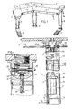
- the table 1 shown in figure 1 is known from Dutch patent application No. 84.03471, whose contents should be regarded as interpolated here.
- the table 1 is provided with a work surface 2, constructed of work surface parts 3, 4 and 5, which are carried by table legs 6 and 8 respectively.
- Table legs 6 and 8 are provided with supporting feet 10 and 11 respectively, while table leg 7 is provided with a distance foot 9.
- Work surface 2 is adjustable in height, through table legs 6, 7 and 8 comprising an upper leg part 15 and a lower leg part 16 telescopically slidable in respect thereof.
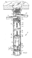
- the table leg 7 (figure 2) comprises two mutually telescopically slidable leg parts 15 and 16, an upper leg part 15 that is provided with screws 12 for fastening to the table top 2, a lower leg part 16 in which is fastened a spindle nut 13, into which is screwed a screw spindle 60 which is mounted at its top and in bearings 14 and is connected at its bottom free end to, suspended freely thereon in the lower leg part, an electric motor 19, which is slidably guided by supports 18 comprising restraining means in longitudinal grooves 17 arranged in the inner, lower leg part 16.
- the electric motor 19 is connected by means of a lead 20 to a foot or hand-operated switch and is provided with a voltage supply through a transformer 21 and a protection circuit 22.
- the electric motor 19 drives screw spindle 60, which drives, via a transmission gear consisting of bevel gear wheels 61 and 62, a connecting shaft 23, which in turn drives, through a similar transmission gear, the screw spindles of table legs 6 and 8 in the same direction.
- the connecting shaft 23 may further be coupled to a crank handle 24 (figure 1) so that hand operation is possible when electric motor 19 has become inoperative or must be disconnected. Usually, the crank handle 24 will no longer be present.
- a conically formed leg support 30 in a conically formed leg support 30 is held a lower leg part 32, in which a ring core transformer 31 is arranged.
- a supply voltage is fed through a connection 33, through which control signals can also be passed to an electric motor 35 from a foot switch (not shown) on the floor or hand switch on the work surface 34.
- a gear box 37 for transmitting the correct force-motion ratio from the electric motor 35, which is for instance a 24V DC motor.
- a relay 39 Further incorporated between the DC motor 35 and transformer 31 and beneath a partition 38 - provided with an opening (not shown) for passage of an electrical supply voltage lead (not shown) to electric motor 35 - are a relay 39, a fuse 40 and a bridge rectifier 41.
- the electric motor 35 and the gearbox 37 are slidably guided via supports 28 of the electric motor in longitudinal grooves 29 in the lower leg part 32, so that upon the turning of the spindle 36 the upper leg part 42, which is cylindrically and telescopically slidable with respect to lower leg part 32, is raised from stop member 43 upwards.
- the table leg 27 is fastened to work top 34 with the aid of a leaf bolt 65. As a result of countersinking into the wood of the work top, a tight-fitting connection with the leaf bolt 65 is obtained.
- the leaf bolt 65 is provided with apertures 66 so that it can be released with a simple spanner.
- leaf bolt 65 takes a symmetrical form
- work top 34 can be reversed in simple manner, so that, for example, the table of figure 1 can easily be embodied in a mirror-image form, which may proved useful for deployment in specific areas.
- connection with use of a leaf bolt can of course also be applied with advantage in the embodiment shown in figure 2.
- the spindle 60 is also provided at its top with a bevel gear wheel 61, but this bevel gear wheel is engaged only with one gear wheel mounted on a transverse shaft 64.
- This transverse shaft 64 is provided at both ends with a square coupling piece 25.
- a coupling shaft 63 On each of the coupling pieces 25 a coupling shaft 63, not shown in the drawing, provided with a corresponding opening can be arranged to connect the leg concerned with other legs.
- This embodiment is distinguished from the embodiment shown in figure 2 in that both connecting shafts 23 have the same direction of rotation, while in the embodiment shown in figure 2 the two coupling shafts 23 have opposite directions of rotation.
Abstract
Description
-
- The present invention relates to a table leg for a table provided with a table top adjustable in height, comprising two mutually telescopically slidable leg parts, an upper leg part which is provided with means for fastening to the table top, a lower leg part which is provided with a spindle nut in which is screwed a screw spindle mounted on the upper leg part, and an electric motor incorporated in the table leg for driving the screw spindle.
- A table leg of the kind is known from DE-A-35.43.-696. The battery-driven electric motor is accommodated in the upper leg part and drives the screw spindle at its upper end. This construction has several disadvantages. Firstly, the load of the table is transmitted to the lower leg part via the electric motor and the screw spindle, an arrangement which necessitates an adequate mounting of the motor in the upper leg part. Secondly, through the electric motor being incorporated in the upper part, it becomes impossible to drive screw spindles of other extensible table legs using one and the same electric motor via connection rods mounted in the top of the upper leg part. Finally, the electric motor is only accessible by unscrewing the table leg from the table top.
- The present invention has for its object to procure a table leg of the kind stated in the preamble which does not have the above-stated disadvantages. This is achieved according to the invention in that the electric motor is connected to the lower free end of the screw spindle and suspended freely thereon in the lower leg part, and that the electric motor and the lower leg part are provided with co-operating restraining means which prevent the electric motor, movable up and down in the lower leg part, from rotating with respect to the lower leg part. In this way, the electric motor moves up and down in the lower leg part whilst suspended on the screw spindle, and the load of the table is transmitted to the lower leg part through the screw spindle and spindle nut. Moreover, the electrical connecting leads for the electric motor can easily be brought up from the floor.
- In preference, the restaining means comprise at least one longitudinal slot arranged in the inner leg part and an electric motor support sliding in this slot.
- In a simple manner, the maximum and minimum extensions of the table leg may be adjusted by use of a first and a second switching means that switches the electric motor off when the table leg reaches its respective maximum or minimum extension. It is advantageous if the first and second switching means are arranged respectively on the top and bottom surfaces of the spindle nut.
- With a single electric motor equipped table leg according to the invention, a number of other telescopically extensible legs can be adjusted in length, if, by preference, the screw spindle in the upper leg part is furthermore coupled with coupling means for coupling to a non-driven screw spindle of another table leg adjustable extension.
- The invention relates further to a table of adjustable height that is provided with at least one table leg according to the invention.
- The table 1 shown in figure 1 is known from Dutch patent application No. 84.03471, whose contents should be regarded as interpolated here. The table 1 is provided with a
work surface 2, constructed ofwork surface parts table legs 6 and 8 respectively.Table legs 6 and 8 are provided with supportingfeet table leg 7 is provided with a distance foot 9.Work surface 2 is adjustable in height, throughtable legs upper leg part 15 and alower leg part 16 telescopically slidable in respect thereof. - The table leg 7 (figure 2) comprises two mutually telescopically
slidable leg parts upper leg part 15 that is provided withscrews 12 for fastening to thetable top 2, alower leg part 16 in which is fastened aspindle nut 13, into which is screwed ascrew spindle 60 which is mounted at its top and inbearings 14 and is connected at its bottom free end to, suspended freely thereon in the lower leg part, anelectric motor 19, which is slidably guided bysupports 18 comprising restraining means inlongitudinal grooves 17 arranged in the inner,lower leg part 16. Theelectric motor 19 is connected by means of a lead 20 to a foot or hand-operated switch and is provided with a voltage supply through atransformer 21 and aprotection circuit 22. On empowerment theelectric motor 19drives screw spindle 60, which drives, via a transmission gear consisting ofbevel gear wheels shaft 23, which in turn drives, through a similar transmission gear, the screw spindles oftable legs 6 and 8 in the same direction. - The connecting
shaft 23 may further be coupled to a crank handle 24 (figure 1) so that hand operation is possible whenelectric motor 19 has become inoperative or must be disconnected. Usually, thecrank handle 24 will no longer be present. - In another embodiment of the table leg according to the invention (figure 3), in a conically formed
leg support 30 is held alower leg part 32, in which aring core transformer 31 is arranged. A supply voltage is fed through aconnection 33, through which control signals can also be passed to anelectric motor 35 from a foot switch (not shown) on the floor or hand switch on the work surface 34. Betweenelectric motor 35, which is suspended freely on thescrew spindle 36, andscrew spindle 36 is arranged, on account of the high revolution speed ofelectric motor 35, agear box 37 for transmitting the correct force-motion ratio from theelectric motor 35, which is for instance a 24V DC motor. Further incorporated between theDC motor 35 andtransformer 31 and beneath a partition 38 - provided with an opening (not shown) for passage of an electrical supply voltage lead (not shown) to electric motor 35 - are arelay 39, a fuse 40 and abridge rectifier 41. Theelectric motor 35 and thegearbox 37 are slidably guided via supports 28 of the electric motor inlongitudinal grooves 29 in thelower leg part 32, so that upon the turning of thespindle 36 theupper leg part 42, which is cylindrically and telescopically slidable with respect tolower leg part 32, is raised fromstop member 43 upwards. - Arranged on the
spindle nut 44 at the upper end ofspindle 36 are twomicroswitches leads electric motor 35. In the lowest position of the table leg shown in figure 3microswitch 45 switches offelectric motor 35, whilst in the fully-extended position of thetable leg 27 thetop surface 48 of thecasing 37 will strike against microswitch 46, whereuponelectric motor 35 will likewise be switched off. The transmission of the motion ofspindle 36 to other table legs takes place throughdrive belts respective pulleys - The
table leg 27 is fastened to work top 34 with the aid of aleaf bolt 65. As a result of countersinking into the wood of the work top, a tight-fitting connection with theleaf bolt 65 is obtained. - This sturdy connection between
table leg 27 and work top 34 is advantageous on account of the forces delivered by the electric motor. - The
leaf bolt 65 is provided withapertures 66 so that it can be released with a simple spanner. - If the
leaf bolt 65 takes a symmetrical form, work top 34 can be reversed in simple manner, so that, for example, the table of figure 1 can easily be embodied in a mirror-image form, which may proved useful for deployment in specific areas. - The connection with use of a leaf bolt can of course also be applied with advantage in the embodiment shown in figure 2.
- In the embodiment shown in figure 4, the
spindle 60 is also provided at its top with abevel gear wheel 61, but this bevel gear wheel is engaged only with one gear wheel mounted on atransverse shaft 64. Thistransverse shaft 64 is provided at both ends with asquare coupling piece 25. On each of the coupling pieces 25 a coupling shaft 63, not shown in the drawing, provided with a corresponding opening can be arranged to connect the leg concerned with other legs. - This embodiment is distinguished from the embodiment shown in figure 2 in that both connecting
shafts 23 have the same direction of rotation, while in the embodiment shown in figure 2 the twocoupling shafts 23 have opposite directions of rotation.
Claims (8)
Priority Applications (1)
| Application Number | Priority Date | Filing Date | Title |
|---|---|---|---|
| AT88200520T ATE58824T1 (en) | 1987-03-20 | 1988-03-18 | TABLE BASE FOR A TABLE WITH HEIGHT-ADJUSTABLE TABLE TOP AND TABLE FOR THEREOF. |
Applications Claiming Priority (2)
| Application Number | Priority Date | Filing Date | Title |
|---|---|---|---|
| NL8700662A NL8700662A (en) | 1987-03-20 | 1987-03-20 | TABLE LEG FOR A HEIGHT-ADJUSTABLE WORKTOP TABLE. |
| NL8700662 | 1987-03-20 |
Publications (2)
| Publication Number | Publication Date |
|---|---|
| EP0283103A1 true EP0283103A1 (en) | 1988-09-21 |
| EP0283103B1 EP0283103B1 (en) | 1990-12-05 |
Family
ID=19849737
Family Applications (1)
| Application Number | Title | Priority Date | Filing Date |
|---|---|---|---|
| EP88200520A Expired - Lifetime EP0283103B1 (en) | 1987-03-20 | 1988-03-18 | Table-leg for a table having a tabletop being adjustable in height, and such a table |
Country Status (6)
| Country | Link |
|---|---|
| EP (1) | EP0283103B1 (en) |
| AT (1) | ATE58824T1 (en) |
| DE (1) | DE3861198D1 (en) |
| ES (1) | ES2020325B3 (en) |
| GR (1) | GR3001174T3 (en) |
| NL (1) | NL8700662A (en) |
Cited By (9)
| Publication number | Priority date | Publication date | Assignee | Title |
|---|---|---|---|---|
| EP0379262A1 (en) * | 1989-01-19 | 1990-07-25 | Van Engeland Management B.V. | Height-adjustable table |
| WO1990013240A1 (en) * | 1989-04-28 | 1990-11-15 | Novireal Ag | Support system |
| EP0463317A1 (en) * | 1990-06-22 | 1992-01-02 | Deutsche Aerospace Airbus Gesellschaft mit beschränkter Haftung | Device for adjusting the height of a clamping arrangement |
| EP1201154A1 (en) | 2000-10-18 | 2002-05-02 | Svenska Kenab Karlshamns Ergonomi AB | Longitudinally adjustable leg assembly |
| US6712008B1 (en) * | 2001-05-11 | 2004-03-30 | Bruce C. Habenicht | Portable computer work station assembly |
| GB2391171B (en) * | 2001-04-19 | 2005-01-26 | Atkinson Vari Tech Ltd | Improvements in and relating to height adjustable furniture |
| EP1604589A1 (en) * | 2004-06-11 | 2005-12-14 | USM Holding AG | Device for adjusting the height of a table |
| WO2010112574A3 (en) * | 2009-03-31 | 2010-12-02 | Logicdata Electronic & Software Entwicklungs Gmbh | Linear drive, table having a linear drive, and motor for the linear drive |
| US20170340103A1 (en) * | 2014-10-24 | 2017-11-30 | Suspa Gmbh | Device for adjusting the height of a first part relative to a second part, a retrofit kit for such a device and height-adjustable system comprising a plurality of such devices |
Citations (3)
| Publication number | Priority date | Publication date | Assignee | Title |
|---|---|---|---|---|
| US2857226A (en) * | 1957-03-21 | 1958-10-21 | American Optical Corp | Adjustable table |
| DE3049357A1 (en) * | 1980-12-29 | 1982-07-29 | Horn GmbH & Co KG, 7062 Rudersberg | Vertically adjustable table with motorised extending legs - has two guide columns formed by legs at tabletop ends for stable support |
| FR2504789A1 (en) * | 1981-05-04 | 1982-11-05 | Sautereau Jacques | Extension for drawing board - consists of motor driving two pulleys connected to endless screw to extend and retract it |
-
1987
- 1987-03-20 NL NL8700662A patent/NL8700662A/en not_active Application Discontinuation
-
1988
- 1988-03-18 EP EP88200520A patent/EP0283103B1/en not_active Expired - Lifetime
- 1988-03-18 DE DE8888200520T patent/DE3861198D1/en not_active Expired - Fee Related
- 1988-03-18 AT AT88200520T patent/ATE58824T1/en not_active IP Right Cessation
- 1988-03-18 ES ES88200520T patent/ES2020325B3/en not_active Expired - Lifetime
-
1990
- 1990-12-06 GR GR90401013T patent/GR3001174T3/en unknown
Patent Citations (3)
| Publication number | Priority date | Publication date | Assignee | Title |
|---|---|---|---|---|
| US2857226A (en) * | 1957-03-21 | 1958-10-21 | American Optical Corp | Adjustable table |
| DE3049357A1 (en) * | 1980-12-29 | 1982-07-29 | Horn GmbH & Co KG, 7062 Rudersberg | Vertically adjustable table with motorised extending legs - has two guide columns formed by legs at tabletop ends for stable support |
| FR2504789A1 (en) * | 1981-05-04 | 1982-11-05 | Sautereau Jacques | Extension for drawing board - consists of motor driving two pulleys connected to endless screw to extend and retract it |
Cited By (13)
| Publication number | Priority date | Publication date | Assignee | Title |
|---|---|---|---|---|
| EP0379262A1 (en) * | 1989-01-19 | 1990-07-25 | Van Engeland Management B.V. | Height-adjustable table |
| WO1990013240A1 (en) * | 1989-04-28 | 1990-11-15 | Novireal Ag | Support system |
| EP0463317A1 (en) * | 1990-06-22 | 1992-01-02 | Deutsche Aerospace Airbus Gesellschaft mit beschränkter Haftung | Device for adjusting the height of a clamping arrangement |
| EP1201154A1 (en) | 2000-10-18 | 2002-05-02 | Svenska Kenab Karlshamns Ergonomi AB | Longitudinally adjustable leg assembly |
| US6478269B2 (en) | 2000-10-18 | 2002-11-12 | Svenska Kenab Karlshamns Ergonomi | Longitudinally adjustable leg assembly |
| GB2391171B (en) * | 2001-04-19 | 2005-01-26 | Atkinson Vari Tech Ltd | Improvements in and relating to height adjustable furniture |
| US6712008B1 (en) * | 2001-05-11 | 2004-03-30 | Bruce C. Habenicht | Portable computer work station assembly |
| EP1604589A1 (en) * | 2004-06-11 | 2005-12-14 | USM Holding AG | Device for adjusting the height of a table |
| US7574965B2 (en) | 2004-06-11 | 2009-08-18 | Usm Holding Ag | Height-adjustment device |
| WO2010112574A3 (en) * | 2009-03-31 | 2010-12-02 | Logicdata Electronic & Software Entwicklungs Gmbh | Linear drive, table having a linear drive, and motor for the linear drive |
| US9093930B2 (en) | 2009-03-31 | 2015-07-28 | Logicdata Electronic & Software Entwicklungs Gmbh | Linear actuator with a rotating brushless DC motor |
| US9642758B2 (en) | 2009-03-31 | 2017-05-09 | Logicdata Electronic & Software Entwicklungs Gmbh | Linear actuator with a rotating brushless DC motor |
| US20170340103A1 (en) * | 2014-10-24 | 2017-11-30 | Suspa Gmbh | Device for adjusting the height of a first part relative to a second part, a retrofit kit for such a device and height-adjustable system comprising a plurality of such devices |
Also Published As
| Publication number | Publication date |
|---|---|
| EP0283103B1 (en) | 1990-12-05 |
| GR3001174T3 (en) | 1992-06-30 |
| ATE58824T1 (en) | 1990-12-15 |
| DE3861198D1 (en) | 1991-01-17 |
| ES2020325B3 (en) | 1991-08-01 |
| NL8700662A (en) | 1988-10-17 |
Similar Documents
| Publication | Publication Date | Title |
|---|---|---|
| US4463463A (en) | Adjustable bed | |
| US3817346A (en) | Mobile scaffolding | |
| EP0283103A1 (en) | Table-leg for a table having a tabletop being adjustable in height, and such a table | |
| US4593883A (en) | Portable lifting, loading and transporting device | |
| AU578788B2 (en) | Universal kitchen machine | |
| EP0908277A3 (en) | Table top convertible into a workbench | |
| US5230290A (en) | Flush-mounted crank | |
| DE60204493D1 (en) | Lifting column preferably for furniture such as tables and beds | |
| US5456191A (en) | Adjustable height counter weighted manual lift table | |
| US5482416A (en) | Metal working machine | |
| EP0500187B1 (en) | Leg structure | |
| EP0379262B1 (en) | Height-adjustable table | |
| EP0426031A1 (en) | Industrial sewing machine, sewing machine table and control pedal | |
| WO1987006439A1 (en) | Desk comprising a desk top that is vertically adjustable within a great range | |
| EP0266171A2 (en) | Transport unit for assembly system | |
| CN216576249U (en) | Intelligent welding robot moving mechanism | |
| EP0629373A1 (en) | Polishing machine | |
| CN219583092U (en) | Rosewood processing positioning and cutting device | |
| US5067703A (en) | Automatic pallet centering device | |
| WO1994016267A1 (en) | A lifting device for the controlled vertical transfer of objects | |
| CN220007936U (en) | Precision board cutting saw with good safety | |
| CN210307131U (en) | Trimmer is used in shrink film production | |
| CN210080832U (en) | Raw material cutting device for workpiece machining | |
| NL1008165C2 (en) | Drive for adjusting construction parts of a piece of furniture. | |
| JPS6132721Y2 (en) |
Legal Events
| Date | Code | Title | Description |
|---|---|---|---|
| PUAI | Public reference made under article 153(3) epc to a published international application that has entered the european phase |
Free format text: ORIGINAL CODE: 0009012 |
|
| AK | Designated contracting states |
Kind code of ref document: A1 Designated state(s): AT BE CH DE ES FR GB GR IT LI NL SE |
|
| 17P | Request for examination filed |
Effective date: 19890320 |
|
| 17Q | First examination report despatched |
Effective date: 19890622 |
|
| ITF | It: translation for a ep patent filed |
Owner name: STUDIO INGG. FISCHETTI & WEBER |
|
| GRAA | (expected) grant |
Free format text: ORIGINAL CODE: 0009210 |
|
| AK | Designated contracting states |
Kind code of ref document: B1 Designated state(s): AT BE CH DE ES FR GB GR IT LI NL SE |
|
| REF | Corresponds to: |
Ref document number: 58824 Country of ref document: AT Date of ref document: 19901215 Kind code of ref document: T |
|
| REF | Corresponds to: |
Ref document number: 3861198 Country of ref document: DE Date of ref document: 19910117 |
|
| ET | Fr: translation filed | ||
| REG | Reference to a national code |
Ref country code: GR Ref legal event code: FG4A Free format text: 3001174 |
|
| PLBE | No opposition filed within time limit |
Free format text: ORIGINAL CODE: 0009261 |
|
| STAA | Information on the status of an ep patent application or granted ep patent |
Free format text: STATUS: NO OPPOSITION FILED WITHIN TIME LIMIT |
|
| 26N | No opposition filed | ||
| ITTA | It: last paid annual fee | ||
| EAL | Se: european patent in force in sweden |
Ref document number: 88200520.0 |
|
| PGFP | Annual fee paid to national office [announced via postgrant information from national office to epo] |
Ref country code: GB Payment date: 19960913 Year of fee payment: 9 |
|
| PGFP | Annual fee paid to national office [announced via postgrant information from national office to epo] |
Ref country code: BE Payment date: 19960917 Year of fee payment: 9 |
|
| PGFP | Annual fee paid to national office [announced via postgrant information from national office to epo] |
Ref country code: SE Payment date: 19960919 Year of fee payment: 9 Ref country code: GR Payment date: 19960919 Year of fee payment: 9 |
|
| PGFP | Annual fee paid to national office [announced via postgrant information from national office to epo] |
Ref country code: AT Payment date: 19960920 Year of fee payment: 9 |
|
| PGFP | Annual fee paid to national office [announced via postgrant information from national office to epo] |
Ref country code: CH Payment date: 19960923 Year of fee payment: 9 |
|
| PGFP | Annual fee paid to national office [announced via postgrant information from national office to epo] |
Ref country code: FR Payment date: 19960927 Year of fee payment: 9 |
|
| PGFP | Annual fee paid to national office [announced via postgrant information from national office to epo] |
Ref country code: NL Payment date: 19960930 Year of fee payment: 9 Ref country code: ES Payment date: 19960930 Year of fee payment: 9 Ref country code: DE Payment date: 19960930 Year of fee payment: 9 |
|
| PG25 | Lapsed in a contracting state [announced via postgrant information from national office to epo] |
Ref country code: GB Effective date: 19970318 Ref country code: AT Effective date: 19970318 |
|
| PG25 | Lapsed in a contracting state [announced via postgrant information from national office to epo] |
Ref country code: SE Effective date: 19970319 Ref country code: ES Free format text: LAPSE BECAUSE OF NON-PAYMENT OF DUE FEES Effective date: 19970319 |
|
| PG25 | Lapsed in a contracting state [announced via postgrant information from national office to epo] |
Ref country code: LI Effective date: 19970331 Ref country code: CH Effective date: 19970331 Ref country code: BE Effective date: 19970331 |
|
| BERE | Be: lapsed |
Owner name: TECHNISCH HANDELS- EN ADVIESBUREAU VAN ENGELAND B Effective date: 19970331 |
|
| PG25 | Lapsed in a contracting state [announced via postgrant information from national office to epo] |
Ref country code: GR Free format text: THE PATENT HAS BEEN ANNULLED BY A DECISION OF A NATIONAL AUTHORITY Effective date: 19970930 |
|
| PG25 | Lapsed in a contracting state [announced via postgrant information from national office to epo] |
Ref country code: NL Effective date: 19971001 |
|
| REG | Reference to a national code |
Ref country code: GR Ref legal event code: MM2A Free format text: 3001174 |
|
| GBPC | Gb: european patent ceased through non-payment of renewal fee |
Effective date: 19970318 |
|
| REG | Reference to a national code |
Ref country code: CH Ref legal event code: PL |
|
| PG25 | Lapsed in a contracting state [announced via postgrant information from national office to epo] |
Ref country code: FR Free format text: LAPSE BECAUSE OF NON-PAYMENT OF DUE FEES Effective date: 19971128 |
|
| NLV4 | Nl: lapsed or anulled due to non-payment of the annual fee |
Effective date: 19971001 |
|
| PG25 | Lapsed in a contracting state [announced via postgrant information from national office to epo] |
Ref country code: DE Effective date: 19971202 |
|
| EUG | Se: european patent has lapsed |
Ref document number: 88200520.0 |
|
| REG | Reference to a national code |
Ref country code: FR Ref legal event code: ST |
|
| REG | Reference to a national code |
Ref country code: ES Ref legal event code: FD2A Effective date: 19990301 |
|
| PG25 | Lapsed in a contracting state [announced via postgrant information from national office to epo] |
Ref country code: IT Free format text: LAPSE BECAUSE OF NON-PAYMENT OF DUE FEES;WARNING: LAPSES OF ITALIAN PATENTS WITH EFFECTIVE DATE BEFORE 2007 MAY HAVE OCCURRED AT ANY TIME BEFORE 2007. THE CORRECT EFFECTIVE DATE MAY BE DIFFERENT FROM THE ONE RECORDED. Effective date: 20050318 |