EP0282601A1 - Automatic analyzer - Google Patents
Automatic analyzer Download PDFInfo
- Publication number
- EP0282601A1 EP0282601A1 EP87906096A EP87906096A EP0282601A1 EP 0282601 A1 EP0282601 A1 EP 0282601A1 EP 87906096 A EP87906096 A EP 87906096A EP 87906096 A EP87906096 A EP 87906096A EP 0282601 A1 EP0282601 A1 EP 0282601A1
- Authority
- EP
- European Patent Office
- Prior art keywords
- reagent
- card
- sample
- automatic analyzer
- reaction cell
- Prior art date
- Legal status (The legal status is an assumption and is not a legal conclusion. Google has not performed a legal analysis and makes no representation as to the accuracy of the status listed.)
- Granted
Links
Images


Classifications
-
- G—PHYSICS
- G01—MEASURING; TESTING
- G01N—INVESTIGATING OR ANALYSING MATERIALS BY DETERMINING THEIR CHEMICAL OR PHYSICAL PROPERTIES
- G01N35/00—Automatic analysis not limited to methods or materials provided for in any single one of groups G01N1/00 - G01N33/00; Handling materials therefor
-
- G—PHYSICS
- G01—MEASURING; TESTING
- G01N—INVESTIGATING OR ANALYSING MATERIALS BY DETERMINING THEIR CHEMICAL OR PHYSICAL PROPERTIES
- G01N35/00—Automatic analysis not limited to methods or materials provided for in any single one of groups G01N1/00 - G01N33/00; Handling materials therefor
- G01N35/00584—Control arrangements for automatic analysers
-
- G—PHYSICS
- G01—MEASURING; TESTING
- G01N—INVESTIGATING OR ANALYSING MATERIALS BY DETERMINING THEIR CHEMICAL OR PHYSICAL PROPERTIES
- G01N35/00—Automatic analysis not limited to methods or materials provided for in any single one of groups G01N1/00 - G01N33/00; Handling materials therefor
- G01N35/02—Automatic analysis not limited to methods or materials provided for in any single one of groups G01N1/00 - G01N33/00; Handling materials therefor using a plurality of sample containers moved by a conveyor system past one or more treatment or analysis stations
- G01N35/025—Automatic analysis not limited to methods or materials provided for in any single one of groups G01N1/00 - G01N33/00; Handling materials therefor using a plurality of sample containers moved by a conveyor system past one or more treatment or analysis stations having a carousel or turntable for reaction cells or cuvettes
-
- G—PHYSICS
- G01—MEASURING; TESTING
- G01N—INVESTIGATING OR ANALYSING MATERIALS BY DETERMINING THEIR CHEMICAL OR PHYSICAL PROPERTIES
- G01N35/00—Automatic analysis not limited to methods or materials provided for in any single one of groups G01N1/00 - G01N33/00; Handling materials therefor
- G01N2035/00346—Heating or cooling arrangements
- G01N2035/00356—Holding samples at elevated temperature (incubation)
- G01N2035/00386—Holding samples at elevated temperature (incubation) using fluid heat transfer medium
- G01N2035/00396—Holding samples at elevated temperature (incubation) using fluid heat transfer medium where the fluid is a liquid
-
- G—PHYSICS
- G01—MEASURING; TESTING
- G01N—INVESTIGATING OR ANALYSING MATERIALS BY DETERMINING THEIR CHEMICAL OR PHYSICAL PROPERTIES
- G01N35/00—Automatic analysis not limited to methods or materials provided for in any single one of groups G01N1/00 - G01N33/00; Handling materials therefor
- G01N2035/00346—Heating or cooling arrangements
- G01N2035/00435—Refrigerated reagent storage
-
- G—PHYSICS
- G01—MEASURING; TESTING
- G01N—INVESTIGATING OR ANALYSING MATERIALS BY DETERMINING THEIR CHEMICAL OR PHYSICAL PROPERTIES
- G01N35/00—Automatic analysis not limited to methods or materials provided for in any single one of groups G01N1/00 - G01N33/00; Handling materials therefor
- G01N35/00584—Control arrangements for automatic analysers
- G01N35/00722—Communications; Identification
- G01N35/00732—Identification of carriers, materials or components in automatic analysers
- G01N2035/00821—Identification of carriers, materials or components in automatic analysers nature of coded information
- G01N2035/00851—Identification of carriers, materials or components in automatic analysers nature of coded information process control parameters
-
- G—PHYSICS
- G01—MEASURING; TESTING
- G01N—INVESTIGATING OR ANALYSING MATERIALS BY DETERMINING THEIR CHEMICAL OR PHYSICAL PROPERTIES
- G01N35/00—Automatic analysis not limited to methods or materials provided for in any single one of groups G01N1/00 - G01N33/00; Handling materials therefor
- G01N35/02—Automatic analysis not limited to methods or materials provided for in any single one of groups G01N1/00 - G01N33/00; Handling materials therefor using a plurality of sample containers moved by a conveyor system past one or more treatment or analysis stations
- G01N35/04—Details of the conveyor system
- G01N2035/0401—Sample carriers, cuvettes or reaction vessels
- G01N2035/0437—Cleaning cuvettes or reaction vessels
-
- Y—GENERAL TAGGING OF NEW TECHNOLOGICAL DEVELOPMENTS; GENERAL TAGGING OF CROSS-SECTIONAL TECHNOLOGIES SPANNING OVER SEVERAL SECTIONS OF THE IPC; TECHNICAL SUBJECTS COVERED BY FORMER USPC CROSS-REFERENCE ART COLLECTIONS [XRACs] AND DIGESTS
- Y10—TECHNICAL SUBJECTS COVERED BY FORMER USPC
- Y10T—TECHNICAL SUBJECTS COVERED BY FORMER US CLASSIFICATION
- Y10T436/00—Chemistry: analytical and immunological testing
- Y10T436/11—Automated chemical analysis
Definitions
- This invention relates to an automatic analyzer operating automatically for biochemical analysis and immunological analysis.
- This invention has been done in view of the situation mentioned above, and its object is to provide a simple automatic analyzer, miniaturized to cope with a need by local hospitals and clinics, very simple in operation and construction, and moderate in cost.
- the automatic analyzer relating to the invention comprises a means for moving a plurality of samples to a sample sucking position, a means for sucking a predetermined quantity of sample at the sample sucking position and pouring dividedly in a reaction cell, a means for moving the reaction cell to an optical measuring position, a means for pouring a reagent corresponding to a measuring item dividedly into the reaction cell, a means for moving a reagent container in which the reagent corresponding to a measuring item is contained to a reagent sucking position, a means for measuring a sample in the reaction cell optically, a means for washing the reaction cell having finished the measurement, an IC card storing various starting command signals and measurement data, a reader/writer for reading command signals of the IC card and writing the measurement data.
- the IC card comprises a starting IC card in which command signals for actuating and controlling organically a sample moving means, a sampling means, a reaction cell moving means, a reagent pouring means, a reagent container moving means, a reagent pouring means, an optical measuring means and washing means are inputted, and a memory IC card storing data measured by the optical measuring means.
- the IC card may be so constructed as to work for both starting and memory at the same time.
- a thermostat comprises disposing a plurality of heating members at predetermined intervals on the bottom of a thermostatic oven constituted of a heating medium, heating temperature in the thermostatic oven uniformly by controlling the heating members separately for temperature by a temperature controller.
- a table holding the reaction cells thereon turns in step by the number one cell less than the number of the reaction cells held on the table so that the reaction cells will be moved intermittently counter to the direction in which the table turns, thus moving the reaction cells one by one intermittently counter to the direction in which the table turns as mentioned.
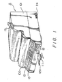
- Fig. 1 is a perspective view showing a general construction of an automatic analyzer given in one embodiment of the invention
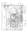
- Fig. 2 is a plan view showing a construction of the automatic analyzer schematically
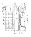
- Fig. 3 is a front view of the automatic analyzer
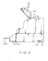
- Fig. 4 is a right side view of the automatic analyzer
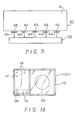
- Fig. 5 is an explanatory drawing showing a schematic construction of a thermostat
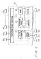
- Fig. 6 is a block diagram showing a construction of a heat regulating block
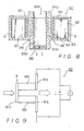
- Fig. 7 is a plan view of a liquid cooling device
- Fig. 8 is a sectional view taken on line VIII - VIa of Fig. 7
- Fig. 9 is a schematic block diagram of an electronic cooling unit
- Fig. 10 is a fragmentary enlarged view showing an example of array of N type semiconductor and P type semiconductor
- Fig. 11 is a fragmentary enlarged view showing another example of array of N type semiconductor and P type semiconductor
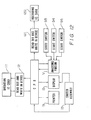
- Fig. 12 is a flowchart showing a construction of the automatic analyzer
- Fig. 13 is an explanatory drawing showing one example of IC card
- Fig. 14 is an explanatory drawing showing one example of display on a display unit.
- a simple automatic analyzer A relating to the invention comprises roughly an analyzing portion V and a controlling portion W.
- the analyzing portion V comprises a reaction cell moving device for moving a reaction cell 1 at a predetermined timing to a sample (serum) pouring position a, a first reagent pouring position b, a second reagent pouring/stirring position c, an optical measuring position d and washing positions e l to e4, a sample container in which a sample (serum) to be measured is contained as required in quantity, a sample container moving device (not indicated) for moving the sample container 2 linearly to a sample sucking position f, a sampling pipet 3 for sucking in a necessary quantity of sample in the sample container 2 and pouring it dividedly into the reaction cell 1, a first reagent pipet 4 for pouring a first reagent corresponding to the measuring item dividedly into the reaction cell 1, a second reagent pipet 5 for pouring a second reagent corresponding to the measuring item into the reaction cell 1, a stirring device (not indicated) interlocking with the second reagent pipet 5, an optical measuring device 7,
- the controlling portion W comprises CPU for controlling a drive of the aforementioned devices correspondingly to the measuring items, a starting IC card 11 ready for reading and writing, a reader/writer 12 on which the starting IC card 11 is installed, a switch group 13 for selecting the analyzing items corresponding to a sample No., a sequential No. and a specified sample No. or sequential No., a display unit 15, a start switch 16, a stop switch 17, a reset switch 18, a memory IC card 120 storing and ready for reading and writing data obtained by the optical measuring device 7, a reader/writer 121 on which the memory IC card 120 is installed, a printer 19 for printing out measuring results and so forth.
- a reference numeral 100 in the drawings denotes a double closing cover mounted rotatably on a case body 101
- a reference numeral 20 in Fig. 3 denotes a sampling pump
- 21 denotes a first reagent pump
- 22 denotes a second reagent pump
- 23 denotes a washing pump
- 24 in Fig. 4 denotes a main switch.
- the reaction cell moving device B moves a plurality (36 pieces) of reaction cells 1 held on a reaction cell table (not indicated) one pitch by one intermittently and successively to required positions as heating up to almost biological temperature (37 °C) on a thermostat 60 described hereinlater.
- the reaction cells 1 turn in step counter (counterclockwise in Fig. 2) to the direction (clockwise in Fig. 2) moved intermittently by the number (for 35 cells) one cell less, thus moving the reaction cells 1 one by one intermittently clockwise in Fig. 2 in consequence, which is the direction counter to the turn in step.
- a well-known pulse motor is used as the reaction cell moving means.
- the sample container 2 is held in a sample cassette 30 in two rows per 10 pieces or in 20 pieces all told, and shaft centers of the containers first, second, third, ... tenth from the right of each row are set so as to come on a path of rotation of the sampling pipet 3.
- the sample cassette 30 holding the sample containers 2 therein as mentioned has the sample containers 2 moved intermittently and successively to the sample sucking position f by the sample container moving device consisting of a cross feed motion.
- the sampling pipet 3 comprises an arm 32 with its one end journaled in a shaft 31, a pipet 33 disposed on the other end of the arm 32, a sampling pump 20 connected through to the pipet 33 and sucking in the sample as required in quantity to discharge to the reaction cells 1, a driving device (not indicated) for turning the arm 32 from the sample sucking position to the sample pouring position a and further to a washing position i at a predetermined timing and then lifting it at each position.
- the sample measuring system then comprises filling a suction system with water, sucking in the sample to measurement as isolated from water through air, discharging the sample only then, and washing the pipet 33 inside with a washing water led therethrough.
- the pipet 33 is set, needless to say, at the pipet washing position i, and hence the sample sticking on an outer surface of the pipet 33 is washed down at the position i.
- the thermostat 60 comprises, as shown in Fig. 5, a heating medium 61 mounted on a thermostatic oven (not indicated) in which a lower portion of the reaction cell 1 soaks, a constant temperature controller 62 disposed on the heating medium 61.
- the constant temperature controller 62 comprises, as shown in Fig. 6, a plurality of temperature detecting elements 63 for detecting temperature at each position of the heating medium 61, a plurality of heating elements 64, a temperature control device 65 for controlling the heating elements 64 according to a temperature information obtained through the temperature detecting elements 63.
- the temperature detecting element 63 is constituted of a thermistor and others and is mounted plurally on a bottom portion of the thermostatic oven separately at predetermined intervals.
- the temperature information obtained through each temperature detecting element 63 has its variation of resistance value converted into voltage by a temperature-voltage converter 66, and an output from the temperature-voltage converter 66 is inputted to the temperature control device 65 for controlling voltage and current to the heating elements 64. Further, the temperature-voltage converter 66 has its output voltage converted into a digital value by an A/D converter 67, an output from the A/D converter 67 and an output from an input device 68 are processed by an arithmetic operation processing circuit 69, and a result thus obtained is converted into an analogue value by a D/A converter 67' and inputted to the temperature control device 65.
- the aforementioned heating element 64 is constituted of a heater utilizing a heat generated by a resistance wire. Further, the temperature control device 65 operates for unifying temperature at each mounting position of the heating medium 61 by subjecting each heating element 64 to on/off control according to information from a temperature detecting element 53.
- the arithmetic operation processing unit 69 operates for the aforementioned arithmetic processing according to a conversion coefficient determined by the temperature-voltage converter 66, a result of the operation is output to the D/A converter 67', and the D/A converter 67' generates a comparison voltage. That is, the D/A converter 67' compares an output voltage from the temperature-voltage converter 66 with the output voltage of the D/A converter 67' generating the aforementioned comparison voltage, the temperature control device 65 controls voltage and current to each temperature detecting element 63 according to the comparison information, thus heating a liquid in the thermostatic oven uniformly.
- a temperature distribution in the thermostat is easily made uniform, and a chemical reaction of the sample with the reagent can be equalized.
- the reagent moving device 10- comprises, as shown in Fig. 2 and Fig. 7, the reagent bottle 9 having a cell 9a in which a first reagent is enclosed and another cell 9b in which a second reagent is enclosed, the bottle moving device (not indicated) turning and controlling a table 40 on which the reagent bottle 9 is placed and moving a reagent corresponding to the measuring item to the first reagent sucking position g or the second reagent sucking position h, the first reagent pipet 4 for sucking the first reagent corresponding to the measuring item as required in quantity from inside the cell 9a at the first reagent sucking position g, the second reagent pipet 5 for sucking the second reagent corresponding to the measuring item as required in quantity from inside the cell 9b at the second reagent sucking position h.
- the reagent bottle 9 disposed on the table 40 is set at a predetermined position, and the position is stored in CPU. Further, the reagent bottle 9 is constituted to have these 12 containers arranged in one set, and where the measuring item varies, the one set is ready for replacing with another set. Then, a reagent in the reagent bottle 9 is cooled down to 10 to 12 °C on a liquid cooling device 80.
- the liquid cooling device 80 comprises, as shown in Fig. 7 to Fig. 10, a heat insulating case 83 circular in plan which is provided with a plurality of chambers 82 for containing the reagent bottle 9 radially therein, a cover 84 installed detachably on an upward opening of the heat insulating case 83, an electronic cooling unit 85 disposed on a center cylindrical part 83a of the heat insulating case 83, a fan 86 for purging forcedly a heat generated in the electronic cooling unit 85 externally.
- the heat insulating case 83 is constituted of a heat insulating material, and comb-toothed radia - tion fins 87, 87 are formed on chamber side of the center cylindrical part 83a as shown in Fig. 8.
- the cover 84 is formed circularly in plan, a void 84b communicating with a central void 83b of the heat insulating case 83 is formed at the central portion thereof, and a peripheral wall portion 84a of the void 84b is projected upward to form a grip. Then, a plurality of openings (not indicated) communicating with holes (not indicated) for sucking liquid in the reagent bottle 9 contained in the heat insulating case 3 are provided on the cover 84 at positions corresponding thereto.
- the electronic cooling unit 85 is constructed fundamentally such that, as shown in Fig. 9, an n-type semiconductor 88 and a p-type semiconductor 89 formed of two different materials are joined together through metals 81a, 81b, 81c, and when DC current is carried from a supply, for example, in the direction indicated by an arrow in Fig. 9, a junction q joined through the metal 81a becomes cool according to an endothermic effect, a junction r joined through the metals 81b, 81c becomes hot according to a heating effect, thus working Peltier effect.
- the n-type semiconductor 88 and the p-type semiconductor 89 are arrayed alternately in the direction circumferential of the center cylindrical part 83a, the chamber sides of the pair of n-type semiconductor 88 and p-type semiconductor 89 are connected through the metal 81a, and the metals 81b, 81c are connected in DC current each to the center void side of the n-type semiconductor 88 and the p-type semiconductor 89, thereby obtaining a low-temperature domain on the chamber side through an endothermic effect and a high-temperature domain on the center void side.
- the pair of n-type semiconductor 88 and p-type semiconductor 89 are disposed longitudinally of the center cylindrical part 83a, the chamber sides of the pair of n-type semiconductor 88 and p-type semiconductor 89 are connected through the metal 81a, the metals 81b, 81c are connected to the center void sides of the n-type semiconductor 88 and the p-type semiconductor 89 respectively, and such set is arrayed plurally on the center cylindrical part 83a in the direction circumferential thereof and then the sets are connected in DC current each other, thus obtaining a low-temperature domain on the chamber side through an endothermic effect and a high-temperature domain on the center void side.
- Peltier effect may be reversible by reversing the direction in which DC current flows, and a similar effect will be obtainable from forming the n-type semiconductor 88 and the p-type semiconductor 89 of an n-type conductor and a p-type conductor respectively.
- a cold air thus generated on the junction q is introduced to the chamber 82 from a radiation fin 87, and a hot air generated on the junction r is exhausted forcedly outside the cooling device, thereby cooling down a liquid in the reagent bottle 9 contained in the chamber 2 efficiently.
- the liquid cooling temperature can be set arbitrarily by regulating voltage of the DC current.
- a heat generated on the junction r can be used, for example, for preliminary heating of the sample.
- the liquid cooling device From constructing the liquid cooling device as described, an evaporator, a condenser and a long passage for guiding cold air are not required unlike a conventional liquid cooling device, the device can sharply be miniaturized, and cold air can be sent directly to the cells, thus enhancing a cooling efficiency at the same time.
- the reagent bottle 9 corresponding to the measuring item arrives at predetermined reagent sucking positions g, h, the reagent is poured dividedly into the reaction cells 1 by the first and second reagent pipets 4, 5.
- the first and second reagent pipets 4, 5 comprise arms 42, 52 with one end journaled in shafts 41, 51 each, pipets 43, 53 disposed on the other ends of the arms 42, 52, pumps 21, 22 connected through to the pipets 43, 53 and sucking in a necessary quantity of the reagent to discharge into the reaction cell 1, each driving device (not indicated) for turning the arms 42, 52 from the reagent sucking positions g, h to the reagent pouring positions b, c-and further to the washing positions j, k at a predetermined timing and controlling a lifting at each position.
- a suction system In measuring the reagent, a suction system is filled with water, the reagent and water are separated each other through air to suction and measurement, the reagent only is then discharged, and a washing water is poured from inside thereafter to wash the interior of the pipets 43, 53.
- the pipets 43, 53 are set at the pipet washing positions j, k, and the sample and others sticking on outer surfaces of the pipets 43, 53 are washed at the positions j, k.
- the stirring device is fixed on the second reagent pipet 5, moved according as the arm 52 is turned, bubbles the sample in the reaction cell 1 immediately after the second reagent is poured, and is then washed together with the second reagent pipet 5 at the pipet washing position k.
- the optical measuring device 7 forming a detecting unit or observation point is constructed in a diffraction grating system, comprising a light source 70, a plurality of light receiving elements 71 with a measuring light irradiated from the light source 70 arrayed on Rowland circle, the aforementioned CPU for converting the quantity of light received on the light receiving element 71 corresponding to a measuring item into voltage and processing the value obtained through analysis, a memory (not indicated) for storing the data.
- the optical measuring device 7 may be applied from changing into a wave-length conversion system through a filter.
- the optical measuring device 7 operates for measuring continuously all the reaction cells 1 (35 all told in the illustrated embodiment) from the washing position e l to a measurement closing position l, thus obtaining a reaction time course of each reaction cell 1.
- the washing device 8 washes the interior of the reaction cell 1 for which the optical measuring work is over for reservice, comprising a known liquid suction motion and a washing water feed motion.
- Known readable/writable IC cards are used for the starting IC card 11 for driving and controlling an automatic analyzer A constructed as above and the memory IC card 120 for storing measuring data.
- a data storage 112 operating on integrated circuit is buried in a card substrate 110, thereby interchanging information with the reader/writer units 12, 121.
- the starting IC card 11 and the memory IC card 120 are provided basically with a light receiving element 113 for receiving optical signals according to data signals sent from the reader/writer units 12, 121 buried in the card substrate 110 and transmitting them to the data storage 112, a light emitting element 114 for converting data signals generated from the reader/writer units 12, 121 buried in the aforementioned card substrate 110 and sending them to the reader/writer units 12, 121, a driving- power supply 115 for generating driving voltages for the data storage 112 and the light receiving element 113 buried in the card substrate 110.
- the starting IC card 11 and the memory IC card 120 have CPU constituting the data storage 112 which is not illustrated, an integrated circuit forming a data store part, a plurality of light receiving elements consisting of a photo transistor for receiving a crystal oscillation signal sent as optical signal from the reader/writer units 12, 121, a data input signal and a reset signal, a light emitting element consisting of a light emitting diode for converting a data output signal from the integrated circuit into an optical signal and outputting it to the reader/writer units 12, 121, a driving power supply such as mercury cell or the like arrayed within the card substrate 110 formed of a synthetic resin such as polyester, vinyl chloride or the like at predetermined positions.
- a driving power supply such as mercury cell or the like arrayed within the card substrate 110 formed of a synthetic resin such as polyester, vinyl chloride or the like at predetermined positions.
- the aforementioned integrated circuit is constituted of E-EPROM (Electrical Erasable Programmable Read Only Memory) not only readable but also rewritable electrically, wherein a drive controlling means coordinating with a plurality of grouped analysis items is inputted, for example, for six groups as shown in Fig. 14, and also various data such as name, registration No., office, post and others of operators using the automatic analyzer A are inputted.
- E-EPROM Electrical Erasable Programmable Read Only Memory
- the analysis items may be grouped by dividing only such items as are necessitated by facilities to install properly into a plurality of groups, however, in consideration of a construction of the automatic analyzer and other factors, it is preferable that the items be grouped by objects of analysis as hepatic function analysis group such as GOT, GPT and the like, kidney function analysis group such as BUN, CRNN, UA and the like, or electrolyte analysis group.
- hepatic function analysis group such as GOT, GPT and the like
- kidney function analysis group such as BUN, CRNN, UA and the like
- electrolyte analysis group electrolyte analysis group.
- a particular of the grouped items which can be analyzed by the starting IC card 11 is indicated together with a sequential No. on the left side of a display portion, as shown in Fig. 14, of a display unit 90 of the automatic analyzer A, and an analysis group No. and a particular of examination of the analysis group are indicated on the right side of the display portion.
- the sequential No. refers to a machine serial number of the sample cell 2, and the sequential No. of the sample cells (20 cells in the illustrated embodiment) set on the automatic analyzer A is indicated vertically.
- the sequential No. will be selected by turning on a suitable switch in the switch group 13.
- the analysis group No. and the particular of examination of the analysis group indicate which switch of the switch group 13 indicates "what" analysis No., i.e. for example, "1" indicates the hepatic function examination group, "3" indicates the kidney function examination group and so forth.
- a start switch 93 is turned on.
- each mechanism of an analyzing portion V operates for a predetermined analyzing work according to a control signal selected by the switch group 13, the analysis data is sent to CPU, printed out on the printer 19 thereafter, and is inputted to the memory IC card 120 to storage through the reader/writer 121.
- operation data read by the reader/writer 121 and operation procedure of the switch group 13 are inputted minutely to the memory IC card 120, and the construction is such that the stored data cannot be fetched normally from within the reader/writer 121 disposed in the automatic analyzer A by those other than a particular person (maintenance personnel, for example).
- the reader/writer units 12, 121 are constructed similarly to a known card reader/writer, which are exemplified by the construction comprising providing a ready access terminal for outputting control signals to the memory IC card 120 and others and another ready access terminal for inputting and outputting operation data and operation procedure of the switch group 13 to the starting IC card 11 and others, disposing reader pack, IC card transmitting/receiving circuit, arithmetic operation part and light source in the interior, which are not so illustrated.
- the reader/writer units 12, 121 constructed as above operate for reading optically operation data inputted to the starting IC card 11 and the memory IC card 120, setting the switch group 13 of the au- tomatic analyzer A to a state ready for use accord- ing to the read data, inputting measuring data obtained through the optical measuring device 7 and operation procedure of the switch group 13 to the starting IC card 11 and the memory IC card 120.
- the automatic analyzer A relating to the embod- iment is set to on (ready) state only in case the starting IC card 11 and the memory IC card 120 are set normally on the reader/writer units 12, 121 respectively, leaving off the subswitch (not indicated) only which is an actuating switch of the switch group 13.
- the subswitch is that for setting the switch group 13 to a ready state only when the starting IC card 11 and the memory IC card 120 are set at predetermined positions of the reader/writer units 12, 121, further the operation data read by the reader/writer units 12, 121 is decided proper, and inputted to the memory IC card 120 to storage.
- the reader/writer 12 irradiates a light to a power pack of the starting IC card 11 from the light source, thereby generating an electromotive force on the card power pack.
- the starting IC card 11 produces a driving voltage from the electromotive force, and all the circuit parts in the starting IC card 11 are set to a ready state.
- a starting data stored in the aforementioned storage feeds an oscillation signal generated from an oscillator of the reader/writer 12 to a predetermined light receiving element of the starting IC card 11, and thus CPU of the starting IC card 11 is actuated to read out the operation data of the data storage.
- the data read by CPU is converted into an optical signal by the predetermined light receiving element and sent to the reader/writer 12.
- the data sent to the reader/writer 12 is subjected to a necessary data processing at the reader/writer 12, the reader/writer 12 then generates an on actuation signal of the switch group 13 to the subswitch, and the operation data is inputted to the memory IC card 120 set on the reader/writer 121.
- the switch group 13 when the switch group 13 is set to a ready state by the starting IC card 11, the operator will manipulate the switch group 13 to input desired analysis conditions and others, and the automatic analyzer A operates for predetermined analysis processing according to the inputted operation procedure, however, the operation procedure by the switch group 13 is also inputted automatically in sequence to the memory IC card 120 through the reader/writer 121.
- the maintenance personnel will set the memory IC card 120 extracted from within the reader/ writer 121 to a predetermined reader installed in another place, dump the data inputted within the memory IC card 120 to CRT, printer and others to read, thus finding the cause of fault of the automatic analyzer A easily and quickly.
- the sample cassette 30 moves each sample cell 2 to the sucking position f, and a work for sucking the sample is carried out by the sampling pipet 3 at the sample sucking position f.
- the sampling pipet 3 is turned thereafter and pours the sample sucked in the reaction cell 1 for necessary quantity.
- the reaction cell 1 turns 35 pitches counterclockwise in Fig. 2 and stops, and then the reaction cell 1 is moved intermittently at every pitch clockwise in Fig. 2.
- the reaction cell 1 repeats an operation to turn 35 pitches counterclockwise in Fig. 2 at every pouring of the sample or at every 20 seconds and then stop.
- the reagent table 40 is controlled for rotation synchronously therewith, the reagent bottle 9a containing a first reagent corresponding to the measuring item is moved to the reagent sucking position g, the first reagent is thus sucked in necessary quantity and poured into the reaction cell 1 having arrived at the first reagent pouring position b.
- the reaction cell 1 is moved to the second reagent pouring/stirring position c, the reagent table 40 is controlled for rotation in concert therewith, the reagent bottle 9b containing a second reagent corresponding to the measuring item is moved to the second reagent sucking position h, a necessary quantity of the second reagent is sucked at the position h by the second reagent pipet 5, poured into the reaction cell 1, and is then bubbled by the stirring device.
- the aforementioned reaction cell 1 is moved successively by the reaction cell moving device B, crosses a luminous flux of the optical measuring device 7 at every 35-pitch rotations counterclockwise in Fig. 2, thus a predetermined optical measurement corresponding to the measuring item is carried out, thereby obtaining a reaction time course of each reaction cell 1.
- reaction cell 1 for which the optical measuring work is over as described is then moved to the washing device 8, and after a predetermined washing is performed therefor, it is again moved to the sample pouring position a.
- the analysis value obtained as above is subjected to a data processing on CPU, printed out to the printer 19, and is then inputted to the memory IC card 120. Then, in case the analysis processing is suspended on the way, a stop switch 94 is turned on, and when using the next starting IC card 11, a reset switch 95 is turned on.
- the invention may be constructed otherwise that the automatic analyzer may be controlled and the measuring data may also be stored by an IC card or magnetic card of large capacity instead of"inputting operator's information and control signals and storing measuring data all by two IC cards.
- a desired analysis item can be selected by IC card, and an item corresponding to the sample can be selected by operating switches on/off accordingly, and hence the operation is extremely simplified, the system can generally be constructed simply and compactedly as well, a simple automatic analyzer troubleless and moderate in cost can thus be provided, therefore an automatic analyzer complying with requirements of hospitals and clinics can be provided at a low cost.
Abstract
Description
- This invention relates to an automatic analyzer operating automatically for biochemical analysis and immunological analysis.
- Various kinds of automatic analyzers have ever been proposed, however, many of the recent automatic analyzers are rather complicated, large-sized, high- costed and high-speed operating, and moreover, involve an exceedingly complicate operation, therefore a specialized operator must be attendant thereon all the time, thus personnel expenses running up to a problem.
- Then, this kind of large-sized automatic analyzer is not inevitably required by local hospitals and clinics where so much blood examination is not necessary, and thus the existing condition is that the specialized examination center is requested for blood examination of respective patients.
- In case, consequently, where an urgent examination is required, an inconvenience may result with such local hospitals and clinics, and a waste of cost is quite unavoidable, moreover, in case a work for comparing an analysis data with the patient's blood or reexamination is required, so long time will be needed for obtaining a result.
- This invention has been done in view of the situation mentioned above, and its object is to provide a simple automatic analyzer, miniaturized to cope with a need by local hospitals and clinics, very simple in operation and construction, and moderate in cost.
- In order to attain the aforementioned object, the automatic analyzer relating to the invention comprises a means for moving a plurality of samples to a sample sucking position, a means for sucking a predetermined quantity of sample at the sample sucking position and pouring dividedly in a reaction cell, a means for moving the reaction cell to an optical measuring position, a means for pouring a reagent corresponding to a measuring item dividedly into the reaction cell, a means for moving a reagent container in which the reagent corresponding to a measuring item is contained to a reagent sucking position, a means for measuring a sample in the reaction cell optically, a means for washing the reaction cell having finished the measurement, an IC card storing various starting command signals and measurement data, a reader/writer for reading command signals of the IC card and writing the measurement data.
- In the invention, the IC card comprises a starting IC card in which command signals for actuating and controlling organically a sample moving means, a sampling means, a reaction cell moving means, a reagent pouring means, a reagent container moving means, a reagent pouring means, an optical measuring means and washing means are inputted, and a memory IC card storing data measured by the optical measuring means. Needless to say, the IC card may be so constructed as to work for both starting and memory at the same time.
- Then, in the invention, a thermostat comprises disposing a plurality of heating members at predetermined intervals on the bottom of a thermostatic oven constituted of a heating medium, heating temperature in the thermostatic oven uniformly by controlling the heating members separately for temperature by a temperature controller.
- Further, in the invention, a table holding the reaction cells thereon turns in step by the number one cell less than the number of the reaction cells held on the table so that the reaction cells will be moved intermittently counter to the direction in which the table turns, thus moving the reaction cells one by one intermittently counter to the direction in which the table turns as mentioned.
- Fig. 1 is a perspective view showing a general construction of an automatic analyzer given in one embodiment of the invention; Fig. 2 is a plan view showing a construction of the automatic analyzer schematically; Fig. 3 is a front view of the automatic analyzer; Fig. 4 is a right side view of the automatic analyzer; Fig. 5 is an explanatory drawing showing a schematic construction of a thermostat; Fig. 6 is a block diagram showing a construction of a heat regulating block; Fig. 7 is a plan view of a liquid cooling device; Fig. 8 is a sectional view taken on line VIII - VIa of Fig. 7; Fig. 9 is a schematic block diagram of an electronic cooling unit; Fig. 10 is a fragmentary enlarged view showing an example of array of N type semiconductor and P type semiconductor; Fig. 11 is a fragmentary enlarged view showing another example of array of N type semiconductor and P type semiconductor; Fig. 12 is a flowchart showing a construction of the automatic analyzer; Fig. 13 is an explanatory drawing showing one example of IC card; Fig. 14 is an explanatory drawing showing one example of display on a display unit.
- The invention will now be described in detail with reference to the accompanying drawings representing one preferred embodiment thereof.
- As shown in Fig. 1 to Fig. 4 and Fig. 12, a simple automatic analyzer A relating to the invention comprises roughly an analyzing portion V and a controlling portion W.
- The analyzing portion V comprises a reaction cell moving device for moving a
reaction cell 1 at a predetermined timing to a sample (serum) pouring position a, a first reagent pouring position b, a second reagent pouring/stirring position c, an optical measuring position d and washing positions el to e4, a sample container in which a sample (serum) to be measured is contained as required in quantity, a sample container moving device (not indicated) for moving thesample container 2 linearly to a sample sucking position f, asampling pipet 3 for sucking in a necessary quantity of sample in thesample container 2 and pouring it dividedly into thereaction cell 1, a first reagent pipet 4 for pouring a first reagent corresponding to the measuring item dividedly into thereaction cell 1, asecond reagent pipet 5 for pouring a second reagent corresponding to the measuring item into thereaction cell 1, a stirring device (not indicated) interlocking with thesecond reagent pipet 5, an optical measuring device 7, a washing device 8, areagent moving device 10 for moving areagent bottle 9 in which the first and second reagents are contained to a first reagent sucking position g or a second reagent sucking position h. - On the other hand, the controlling portion W comprises CPU for controlling a drive of the aforementioned devices correspondingly to the measuring items, a starting
IC card 11 ready for reading and writing, a reader/writer 12 on which the startingIC card 11 is installed, aswitch group 13 for selecting the analyzing items corresponding to a sample No., a sequential No. and a specified sample No. or sequential No., adisplay unit 15, astart switch 16, astop switch 17, areset switch 18, amemory IC card 120 storing and ready for reading and writing data obtained by the optical measuring device 7, a reader/writer 121 on which thememory IC card 120 is installed, aprinter 19 for printing out measuring results and so forth. Then, areference numeral 100 in the drawings denotes a double closing cover mounted rotatably on acase body 101, areference numeral 20 in Fig. 3 denotes a sampling pump, 21 denotes a first reagent pump, 22 denotes a second reagent pump, 23 denotes a washing pump, and 24 in Fig. 4 denotes a main switch. - The reaction cell moving device B moves a plurality (36 pieces) of
reaction cells 1 held on a reaction cell table (not indicated) one pitch by one intermittently and successively to required positions as heating up to almost biological temperature (37 °C) on athermostat 60 described hereinlater. Thereaction cells 1 turn in step counter (counterclockwise in Fig. 2) to the direction (clockwise in Fig. 2) moved intermittently by the number (for 35 cells) one cell less, thus moving thereaction cells 1 one by one intermittently clockwise in Fig. 2 in consequence, which is the direction counter to the turn in step. A well-known pulse motor is used as the reaction cell moving means. - The
sample container 2 is held in asample cassette 30 in two rows per 10 pieces or in 20 pieces all told, and shaft centers of the containers first, second, third, ... tenth from the right of each row are set so as to come on a path of rotation of thesampling pipet 3. - The
sample cassette 30 holding thesample containers 2 therein as mentioned has thesample containers 2 moved intermittently and successively to the sample sucking position f by the sample container moving device consisting of a cross feed motion. - As in the case of a well-known sampling pipet, the
sampling pipet 3 comprises an arm 32 with its one end journaled in ashaft 31, a pipet 33 disposed on the other end of the arm 32, asampling pump 20 connected through to the pipet 33 and sucking in the sample as required in quantity to discharge to thereaction cells 1, a driving device (not indicated) for turning the arm 32 from the sample sucking position to the sample pouring position a and further to a washing position i at a predetermined timing and then lifting it at each position. - The sample measuring system then comprises filling a suction system with water, sucking in the sample to measurement as isolated from water through air, discharging the sample only then, and washing the pipet 33 inside with a washing water led therethrough. In this case, the pipet 33 is set, needless to say, at the pipet washing position i, and hence the sample sticking on an outer surface of the pipet 33 is washed down at the position i.
- The
thermostat 60 comprises, as shown in Fig. 5, aheating medium 61 mounted on a thermostatic oven (not indicated) in which a lower portion of thereaction cell 1 soaks, aconstant temperature controller 62 disposed on theheating medium 61. - The
constant temperature controller 62 comprises, as shown in Fig. 6, a plurality oftemperature detecting elements 63 for detecting temperature at each position of theheating medium 61, a plurality ofheating elements 64, a temperature control device 65 for controlling theheating elements 64 according to a temperature information obtained through thetemperature detecting elements 63. - The
temperature detecting element 63 is constituted of a thermistor and others and is mounted plurally on a bottom portion of the thermostatic oven separately at predetermined intervals. - The temperature information obtained through each
temperature detecting element 63 has its variation of resistance value converted into voltage by a temperature-voltage converter 66, and an output from the temperature-voltage converter 66 is inputted to the temperature control device 65 for controlling voltage and current to theheating elements 64. Further, the temperature-voltage converter 66 has its output voltage converted into a digital value by an A/D converter 67, an output from the A/D converter 67 and an output from aninput device 68 are processed by an arithmeticoperation processing circuit 69, and a result thus obtained is converted into an analogue value by a D/A converter 67' and inputted to the temperature control device 65. - Then, the
aforementioned heating element 64 is constituted of a heater utilizing a heat generated by a resistance wire. Further, the temperature control device 65 operates for unifying temperature at each mounting position of theheating medium 61 by subjecting eachheating element 64 to on/off control according to information from atemperature detecting element 53. - Therefore, when temperature information corresponding to a set temperature is inputted to the
input device 68, an output from theinput device 68 is inputted to the aforementioned arithmeticoperation processing unit 69, and a corresponding resistance value (for generating a heating power necessary for liquid to be heated and so retained at 37 °C) in eachtemperature detecting element 63 is obtained according to a predetermined arithmetic expression. On the other hand, a change in resistance value of eachtemperature detecting element 63 is converted into voltage by the temperature-voltage converter 66, converted further into a digital signal by the A/D converter 67, and the digital value is inputted to the arithmeticoperation processing unit 69. The arithmeticoperation processing unit 69 operates for the aforementioned arithmetic processing according to a conversion coefficient determined by the temperature-voltage converter 66, a result of the operation is output to the D/A converter 67', and the D/A converter 67' generates a comparison voltage. That is, the D/A converter 67' compares an output voltage from the temperature-voltage converter 66 with the output voltage of the D/A converter 67' generating the aforementioned comparison voltage, the temperature control device 65 controls voltage and current to eachtemperature detecting element 63 according to the comparison information, thus heating a liquid in the thermostatic oven uniformly. - From constructing the
thermostat 60 as mentioned, a temperature distribution in the thermostat is easily made uniform, and a chemical reaction of the sample with the reagent can be equalized. - The reagent moving device 10-comprises, as shown in Fig. 2 and Fig. 7, the
reagent bottle 9 having acell 9a in which a first reagent is enclosed and anothercell 9b in which a second reagent is enclosed, the bottle moving device (not indicated) turning and controlling a table 40 on which thereagent bottle 9 is placed and moving a reagent corresponding to the measuring item to the first reagent sucking position g or the second reagent sucking position h, the first reagent pipet 4 for sucking the first reagent corresponding to the measuring item as required in quantity from inside thecell 9a at the first reagent sucking position g, thesecond reagent pipet 5 for sucking the second reagent corresponding to the measuring item as required in quantity from inside thecell 9b at the second reagent sucking position h. Then, thereagent bottle 9 disposed on the table 40 is set at a predetermined position, and the position is stored in CPU. Further, thereagent bottle 9 is constituted to have these 12 containers arranged in one set, and where the measuring item varies, the one set is ready for replacing with another set. Then, a reagent in thereagent bottle 9 is cooled down to 10 to 12 °C on aliquid cooling device 80. - The
liquid cooling device 80 comprises, as shown in Fig. 7 to Fig. 10, aheat insulating case 83 circular in plan which is provided with a plurality ofchambers 82 for containing thereagent bottle 9 radially therein, acover 84 installed detachably on an upward opening of theheat insulating case 83, anelectronic cooling unit 85 disposed on a centercylindrical part 83a of theheat insulating case 83, afan 86 for purging forcedly a heat generated in theelectronic cooling unit 85 externally. - The
heat insulating case 83 is constituted of a heat insulating material, and comb-toothed radia- tion fins 87, 87 are formed on chamber side of the centercylindrical part 83a as shown in Fig. 8. - As in the case of the aforementioned
heat insulating case 83, thecover 84 is formed circularly in plan, avoid 84b communicating with acentral void 83b of theheat insulating case 83 is formed at the central portion thereof, and aperipheral wall portion 84a of thevoid 84b is projected upward to form a grip. Then, a plurality of openings (not indicated) communicating with holes (not indicated) for sucking liquid in thereagent bottle 9 contained in theheat insulating case 3 are provided on thecover 84 at positions corresponding thereto. - The
electronic cooling unit 85 is constructed fundamentally such that, as shown in Fig. 9, an n-type semiconductor 88 and a p-type semiconductor 89 formed of two different materials are joined together throughmetals metal 81a becomes cool according to an endothermic effect, a junction r joined through themetals 81b, 81c becomes hot according to a heating effect, thus working Peltier effect. - Accordingly, as shown in Fig. 10, the n-
type semiconductor 88 and the p-type semiconductor 89 are arrayed alternately in the direction circumferential of the centercylindrical part 83a, the chamber sides of the pair of n-type semiconductor 88 and p-type semiconductor 89 are connected through themetal 81a, and themetals 81b, 81c are connected in DC current each to the center void side of the n-type semiconductor 88 and the p-type semiconductor 89, thereby obtaining a low-temperature domain on the chamber side through an endothermic effect and a high-temperature domain on the center void side. - Then, as another method for arraying the n-
type semiconductor 88 and the p-type semiconductor 89, as shown in Fig. 11, the pair of n-type semiconductor 88 and p-type semiconductor 89 are disposed longitudinally of the centercylindrical part 83a, the chamber sides of the pair of n-type semiconductor 88 and p-type semiconductor 89 are connected through themetal 81a, themetals 81b, 81c are connected to the center void sides of the n-type semiconductor 88 and the p-type semiconductor 89 respectively, and such set is arrayed plurally on the centercylindrical part 83a in the direction circumferential thereof and then the sets are connected in DC current each other, thus obtaining a low-temperature domain on the chamber side through an endothermic effect and a high-temperature domain on the center void side. - Needless to say, Peltier effect may be reversible by reversing the direction in which DC current flows, and a similar effect will be obtainable from forming the n-
type semiconductor 88 and the p-type semiconductor 89 of an n-type conductor and a p-type conductor respectively. - A cold air thus generated on the junction q is introduced to the
chamber 82 from aradiation fin 87, and a hot air generated on the junction r is exhausted forcedly outside the cooling device, thereby cooling down a liquid in thereagent bottle 9 contained in thechamber 2 efficiently. - Then, the liquid cooling temperature can be set arbitrarily by regulating voltage of the DC current. Needless to say, a heat generated on the junction r can be used, for example, for preliminary heating of the sample.
- From constructing the liquid cooling device as described, an evaporator, a condenser and a long passage for guiding cold air are not required unlike a conventional liquid cooling device, the device can sharply be miniaturized, and cold air can be sent directly to the cells, thus enhancing a cooling efficiency at the same time.
- When the
reagent bottle 9 corresponding to the measuring item arrives at predetermined reagent sucking positions g, h, the reagent is poured dividedly into thereaction cells 1 by the first andsecond reagent pipets 4, 5. - As in the construction of a known pipet device, the first and
second reagent pipets 4, 5 comprisearms 42, 52 with one end journaled inshafts 41, 51 each,pipets arms 42, 52,pumps pipets reaction cell 1, each driving device (not indicated) for turning thearms 42, 52 from the reagent sucking positions g, h to the reagent pouring positions b, c-and further to the washing positions j, k at a predetermined timing and controlling a lifting at each position. - In measuring the reagent, a suction system is filled with water, the reagent and water are separated each other through air to suction and measurement, the reagent only is then discharged, and a washing water is poured from inside thereafter to wash the interior of the
pipets pipets pipets - While not indicated, the stirring device is fixed on the
second reagent pipet 5, moved according as thearm 52 is turned, bubbles the sample in thereaction cell 1 immediately after the second reagent is poured, and is then washed together with thesecond reagent pipet 5 at the pipet washing position k. - The optical measuring device 7 forming a detecting unit or observation point is constructed in a diffraction grating system, comprising a
light source 70, a plurality oflight receiving elements 71 with a measuring light irradiated from thelight source 70 arrayed on Rowland circle, the aforementioned CPU for converting the quantity of light received on thelight receiving element 71 corresponding to a measuring item into voltage and processing the value obtained through analysis, a memory (not indicated) for storing the data. Needless to say, the optical measuring device 7 may be applied from changing into a wave-length conversion system through a filter. - Accordingly, the optical measuring device 7 operates for measuring continuously all the reaction cells 1 (35 all told in the illustrated embodiment) from the washing position el to a measurement closing position ℓ, thus obtaining a reaction time course of each
reaction cell 1. - The washing device 8 washes the interior of the
reaction cell 1 for which the optical measuring work is over for reservice, comprising a known liquid suction motion and a washing water feed motion. - Known readable/writable IC cards are used for the starting
IC card 11 for driving and controlling an automatic analyzer A constructed as above and thememory IC card 120 for storing measuring data. - As exemplified in Fig. 13, a
data storage 112 operating on integrated circuit is buried in acard substrate 110, thereby interchanging information with the reader/writer units - That is, the starting
IC card 11 and thememory IC card 120 are provided basically with alight receiving element 113 for receiving optical signals according to data signals sent from the reader/writer units card substrate 110 and transmitting them to thedata storage 112, alight emitting element 114 for converting data signals generated from the reader/writer units aforementioned card substrate 110 and sending them to the reader/writer units power supply 115 for generating driving voltages for thedata storage 112 and thelight receiving element 113 buried in thecard substrate 110. - Then, the starting
IC card 11 and thememory IC card 120 have CPU constituting thedata storage 112 which is not illustrated, an integrated circuit forming a data store part, a plurality of light receiving elements consisting of a photo transistor for receiving a crystal oscillation signal sent as optical signal from the reader/writer units writer units card substrate 110 formed of a synthetic resin such as polyester, vinyl chloride or the like at predetermined positions. - The aforementioned integrated circuit is constituted of E-EPROM (Electrical Erasable Programmable Read Only Memory) not only readable but also rewritable electrically, wherein a drive controlling means coordinating with a plurality of grouped analysis items is inputted, for example, for six groups as shown in Fig. 14, and also various data such as name, registration No., office, post and others of operators using the automatic analyzer A are inputted.
- The analysis items may be grouped by dividing only such items as are necessitated by facilities to install properly into a plurality of groups, however, in consideration of a construction of the automatic analyzer and other factors, it is preferable that the items be grouped by objects of analysis as hepatic function analysis group such as GOT, GPT and the like, kidney function analysis group such as BUN, CRNN, UA and the like, or electrolyte analysis group.
- In this case, a particular of the grouped items which can be analyzed by the starting
IC card 11 is indicated together with a sequential No. on the left side of a display portion, as shown in Fig. 14, of adisplay unit 90 of the automatic analyzer A, and an analysis group No. and a particular of examination of the analysis group are indicated on the right side of the display portion. The sequential No. refers to a machine serial number of thesample cell 2, and the sequential No. of the sample cells (20 cells in the illustrated embodiment) set on the automatic analyzer A is indicated vertically. The sequential No. will be selected by turning on a suitable switch in theswitch group 13. On the other hand, the analysis group No. and the particular of examination of the analysis group indicate which switch of theswitch group 13 indicates "what" analysis No., i.e. for example, "1" indicates the hepatic function examination group, "3" indicates the kidney function examination group and so forth. - Accordingly, if the switch "3" of the
switch group 13 is turned on for the sample of sequential No. 2, then the selected analysis item No. "3" is indicated by the sequential No. "2" of the display portion. - Then, after selection of the analysis item to all the sequential Nos. is over and the ensuring work is completed therefor, a
start switch 93 is turned on. When thestart switch 93 is turned on, each mechanism of an analyzing portion V operates for a predetermined analyzing work according to a control signal selected by theswitch group 13, the analysis data is sent to CPU, printed out on theprinter 19 thereafter, and is inputted to thememory IC card 120 to storage through the reader/writer 121. - Then, operation data read by the reader/
writer 121 and operation procedure of theswitch group 13 are inputted minutely to thememory IC card 120, and the construction is such that the stored data cannot be fetched normally from within the reader/writer 121 disposed in the automatic analyzer A by those other than a particular person (maintenance personnel, for example). - The reader/
writer units memory IC card 120 and others and another ready access terminal for inputting and outputting operation data and operation procedure of theswitch group 13 to the startingIC card 11 and others, disposing reader pack, IC card transmitting/receiving circuit, arithmetic operation part and light source in the interior, which are not so illustrated. - The reader/
writer units IC card 11 and thememory IC card 120, setting theswitch group 13 of the au- tomatic analyzer A to a state ready for use accord- ing to the read data, inputting measuring data obtained through the optical measuring device 7 and operation procedure of theswitch group 13 to the startingIC card 11 and thememory IC card 120. - The automatic analyzer A relating to the embod- iment is set to on (ready) state only in case the starting
IC card 11 and thememory IC card 120 are set normally on the reader/writer units switch group 13. The subswitch is that for setting theswitch group 13 to a ready state only when the startingIC card 11 and thememory IC card 120 are set at predetermined positions of the reader/writer units writer units memory IC card 120 to storage. - A function will be described in the above-described construction.
- First, when the starting
IC card 11 with a predetermined operation data inputted therein is inserted in the reader/writer 12 through a corresponding card insertion port, the reader/writer 12 irradiates a light to a power pack of the startingIC card 11 from the light source, thereby generating an electromotive force on the card power pack. Thus the startingIC card 11 produces a driving voltage from the electromotive force, and all the circuit parts in the startingIC card 11 are set to a ready state. - Then, a starting data stored in the aforementioned storage feeds an oscillation signal generated from an oscillator of the reader/
writer 12 to a predetermined light receiving element of the startingIC card 11, and thus CPU of the startingIC card 11 is actuated to read out the operation data of the data storage. The data read by CPU is converted into an optical signal by the predetermined light receiving element and sent to the reader/writer 12. The data sent to the reader/writer 12 is subjected to a necessary data processing at the reader/writer 12, the reader/writer 12 then generates an on actuation signal of theswitch group 13 to the subswitch, and the operation data is inputted to thememory IC card 120 set on the reader/writer 121. - On the other hand, when the
switch group 13 is set to a ready state by the startingIC card 11, the operator will manipulate theswitch group 13 to input desired analysis conditions and others, and the automatic analyzer A operates for predetermined analysis processing according to the inputted operation procedure, however, the operation procedure by theswitch group 13 is also inputted automatically in sequence to thememory IC card 120 through the reader/writer 121. - Accordingly, if a fault arises on the automatic analyzer A, the maintenance personnel will set the
memory IC card 120 extracted from within the reader/writer 121 to a predetermined reader installed in another place, dump the data inputted within thememory IC card 120 to CRT, printer and others to read, thus finding the cause of fault of the automatic analyzer A easily and quickly. - Next, from actuating the
start switch 93, thesample cassette 30 moves eachsample cell 2 to the sucking position f, and a work for sucking the sample is carried out by thesampling pipet 3 at the sample sucking position f. Thesampling pipet 3 is turned thereafter and pours the sample sucked in thereaction cell 1 for necessary quantity. - When the above work is over, the
reaction cell 1 turns 35 pitches counterclockwise in Fig. 2 and stops, and then thereaction cell 1 is moved intermittently at every pitch clockwise in Fig. 2. Thus thereaction cell 1 repeats an operation to turn 35 pitches counterclockwise in Fig. 2 at every pouring of the sample or at every 20 seconds and then stop. - When the
reaction cell 1 arrives at the first reagent pouring position b on the reaction cell moving device, the reagent table 40 is controlled for rotation synchronously therewith, thereagent bottle 9a containing a first reagent corresponding to the measuring item is moved to the reagent sucking position g, the first reagent is thus sucked in necessary quantity and poured into thereaction cell 1 having arrived at the first reagent pouring position b. - After that, the
reaction cell 1 is moved to the second reagent pouring/stirring position c, the reagent table 40 is controlled for rotation in concert therewith, thereagent bottle 9b containing a second reagent corresponding to the measuring item is moved to the second reagent sucking position h, a necessary quantity of the second reagent is sucked at the position h by thesecond reagent pipet 5, poured into thereaction cell 1, and is then bubbled by the stirring device. - Next, the
aforementioned reaction cell 1 is moved successively by the reaction cell moving device B, crosses a luminous flux of the optical measuring device 7 at every 35-pitch rotations counterclockwise in Fig. 2, thus a predetermined optical measurement corresponding to the measuring item is carried out, thereby obtaining a reaction time course of eachreaction cell 1. - The
reaction cell 1 for which the optical measuring work is over as described is then moved to the washing device 8, and after a predetermined washing is performed therefor, it is again moved to the sample pouring position a. - The analysis value obtained as above is subjected to a data processing on CPU, printed out to the
printer 19, and is then inputted to thememory IC card 120. Then, in case the analysis processing is suspended on the way, astop switch 94 is turned on, and when using the nextstarting IC card 11, areset switch 95 is turned on. - Then, in the above-described embodiment, the case where a contactless optical card is applied for the IC card is exemplified for description, however, the invention is not necessarily limited thereto, and an IC card of contact system, for example, can . also be used.
- Further, in the embodiment described above, the case where one group is selected from among a plurality of analysis groups by an item switch 14 is exemplified, however, a single item such as GOT, GPT, ZTT or the like only may be selected otherwise.
- Still further, the invention may be constructed otherwise that the automatic analyzer may be controlled and the measuring data may also be stored by an IC card or magnetic card of large capacity instead of"inputting operator's information and control signals and storing measuring data all by two IC cards.
- As described in detail above, according to the invention, a desired analysis item can be selected by IC card, and an item corresponding to the sample can be selected by operating switches on/off accordingly, and hence the operation is extremely simplified, the system can generally be constructed simply and compactedly as well, a simple automatic analyzer troubleless and moderate in cost can thus be provided, therefore an automatic analyzer complying with requirements of hospitals and clinics can be provided at a low cost.
Claims (6)
- (1) An automatic analyzer,, comprising a means for moving a plurality of samples to a sample sucking position, a means for sucking a necessary quantity of sample at the sample sucking position and pouring it dividedly into a reaction cell, a means for moving the reaction cell to an optical measuring position, a means for pouring a reagent corresponding to a measuring item dividedly into said reaction cell, a means for moving a reagent cell containing the reagent corresponding to the measuring item therein to a 'reagent sucking position, a means for measuring a sample in the reaction cell optically, a means for washing the reaction cell for which a measurement is over, an IC card for storing various starting command signals and measuring data therein, a reader/writer for reading command signals of the IC card and writing the measuring data.
- (2) The automatic analyzer as defined in claim 1, said starting information comprising a signal necessary for actuating the automatic analyzer, a coded information such as operator's name, registration No., office, post and so forth.
- (3) The automatic analyzer as defined in claim 1, said IC card comprising a starting IC card and a memory IC card.
- (4) The automatic analyzer as defined in any of claim 1, 2 or 3, wherein a starting command signal and a memory part are formed in said IC card.
- (5) The automatic analyzer as defined in any of claim 1, 2, 3 or 4, wherein a thermostat comprises disposing a plurality of heating members at necessary intervals on the bottom surface of a thermostatic oven constituted of a heating medium, heating temperature in the thermostatic oven uniformly by controlling each heating member individually for temperature according to a temperature control device.
- (6) The automatic analyzer as defined in any of claim 1, 2, 3, 4 or 5, wherein said reaction cell rotates in step by the number one cell less than the number of reaction cells retained on a table so as to be moved intermittently counter to the direction in which the table retaining the reaction cells thereon rotates, thus the reaction cells are moved consequently one by one intermittently counter to the direction in which the reaction cell rotates in step.
Priority Applications (1)
| Application Number | Priority Date | Filing Date | Title |
|---|---|---|---|
| AT87906096T ATE85709T1 (en) | 1986-09-16 | 1987-09-16 | AUTOMATIC ANALYZER. |
Applications Claiming Priority (10)
| Application Number | Priority Date | Filing Date | Title |
|---|---|---|---|
| JP21601186 | 1986-09-16 | ||
| JP216011/86 | 1986-09-16 | ||
| JP219174/86 | 1986-09-19 | ||
| JP21917486 | 1986-09-19 | ||
| JP23429586 | 1986-10-03 | ||
| JP234295/86 | 1986-10-03 | ||
| JP811287 | 1987-01-19 | ||
| JP8112/87 | 1987-01-19 | ||
| JP1775087 | 1987-02-12 | ||
| JP17750/87U | 1987-02-12 |
Publications (3)
| Publication Number | Publication Date |
|---|---|
| EP0282601A1 true EP0282601A1 (en) | 1988-09-21 |
| EP0282601A4 EP0282601A4 (en) | 1989-01-17 |
| EP0282601B1 EP0282601B1 (en) | 1993-02-10 |
Family
ID=27518900
Family Applications (1)
| Application Number | Title | Priority Date | Filing Date |
|---|---|---|---|
| EP87906096A Expired - Lifetime EP0282601B1 (en) | 1986-09-16 | 1987-09-16 | Automatic analyzer |
Country Status (12)
| Country | Link |
|---|---|
| US (1) | US4919887A (en) |
| EP (1) | EP0282601B1 (en) |
| JP (1) | JPH0572548B1 (en) |
| KR (1) | KR960009767B1 (en) |
| CN (1) | CN1014551B (en) |
| AT (1) | ATE85709T1 (en) |
| AU (1) | AU597433B2 (en) |
| DE (1) | DE3784161T2 (en) |
| DK (1) | DK258188A (en) |
| FI (1) | FI882258A (en) |
| NO (1) | NO882029L (en) |
| WO (1) | WO1988002120A1 (en) |
Cited By (4)
| Publication number | Priority date | Publication date | Assignee | Title |
|---|---|---|---|---|
| FR2655426A1 (en) * | 1989-12-04 | 1991-06-07 | Nittec Co Ltd | |
| US5215714A (en) * | 1988-04-08 | 1993-06-01 | Toa Medical Electronics Co., Ltd. | Immunoagglutination measurement apparatus |
| EP0637750A2 (en) * | 1993-08-05 | 1995-02-08 | Roche Diagnostics GmbH | Method for analysing sample fluids |
| EP0851232A1 (en) * | 1995-09-05 | 1998-07-01 | Hitachi, Ltd. | Automatic analizer and display method |
Families Citing this family (74)
| Publication number | Priority date | Publication date | Assignee | Title |
|---|---|---|---|---|
| JP2761385B2 (en) * | 1988-04-08 | 1998-06-04 | 東亜医用電子株式会社 | Immunoagglutination measuring device |
| US5298502A (en) * | 1988-12-12 | 1994-03-29 | Fmc Corporation | Method and composition for photodynamic treatment and detection of tumors |
| US5223222A (en) * | 1989-03-13 | 1993-06-29 | Beckman Instruments, Inc. | Automatic chemistry analyzer |
| US5130095A (en) * | 1989-03-13 | 1992-07-14 | Beckman Instruments, Inc. | Automatic chemistry analyzer |
| US5213762A (en) * | 1989-03-13 | 1993-05-25 | Beckman Instruments, Inc. | Automatic chemistry analyzer |
| DE68910304T2 (en) * | 1989-03-15 | 1994-02-24 | Hewlett Packard Co | Follow-up rules for pre-injecting samples to be analyzed by chromatography. |
| AU5387390A (en) * | 1989-04-25 | 1990-11-01 | Biotrack, Inc. | System for modifying output of an analytical instrument |
| IE78906B1 (en) * | 1989-12-01 | 1998-03-11 | Akzo Nv | Sample handling system for an optical monitoring system |
| US5646046A (en) * | 1989-12-01 | 1997-07-08 | Akzo Nobel N.V. | Method and instrument for automatically performing analysis relating to thrombosis and hemostasis |
| US5236666A (en) * | 1989-12-01 | 1993-08-17 | Akzo N.V. | Temperature regulation in a sample handling system for an optical monitoring system |
| EP0517835B1 (en) * | 1990-03-02 | 1996-02-07 | Ventana Medical Systems | Automated biological reaction apparatus |
| US5595707A (en) * | 1990-03-02 | 1997-01-21 | Ventana Medical Systems, Inc. | Automated biological reaction apparatus |
| FR2672126B1 (en) * | 1990-11-16 | 1994-04-08 | Alcyon Analyser Sa | REACTIONAL SEGMENT FOR AUTOMATIC SAMPLE ANALYZER AND ANALYZER EQUIPPED WITH A SEGMENT. |
| DE69125797T2 (en) * | 1990-11-28 | 1997-10-09 | Hitachi Ltd | Analysis method and device for liquid samples |
| FR2679661B1 (en) * | 1991-07-26 | 1994-10-14 | Sfri | APPARATUS FOR AUTOMATIC SAMPLES ANALYSIS. |
| US5536471A (en) | 1992-03-27 | 1996-07-16 | Abbott Laboratories | Syringe with bubble flushing |
| US5635364A (en) | 1992-03-27 | 1997-06-03 | Abbott Laboratories | Assay verification control for an automated analytical system |
| US5960160A (en) | 1992-03-27 | 1999-09-28 | Abbott Laboratories | Liquid heater assembly with a pair temperature controlled electric heating elements and a coiled tube therebetween |
| US5610069A (en) | 1992-03-27 | 1997-03-11 | Abbott Laboratories | Apparatus and method for washing clinical apparatus |
| US5578494A (en) | 1992-03-27 | 1996-11-26 | Abbott Laboratories | Cap actuator for opening and closing a container |
| US5605665A (en) | 1992-03-27 | 1997-02-25 | Abbott Laboratories | Reaction vessel |
| US5376313A (en) | 1992-03-27 | 1994-12-27 | Abbott Laboratories | Injection molding a plastic assay cuvette having low birefringence |
| US6190617B1 (en) | 1992-03-27 | 2001-02-20 | Abbott Laboratories | Sample container segment assembly |
| US5575978A (en) | 1992-03-27 | 1996-11-19 | Abbott Laboratories | Sample container segment assembly |
| US5540890A (en) | 1992-03-27 | 1996-07-30 | Abbott Laboratories | Capped-closure for a container |
| US5646049A (en) | 1992-03-27 | 1997-07-08 | Abbott Laboratories | Scheduling operation of an automated analytical system |
| US5507410A (en) | 1992-03-27 | 1996-04-16 | Abbott Laboratories | Meia cartridge feeder |
| US5627522A (en) | 1992-03-27 | 1997-05-06 | Abbott Laboratories | Automated liquid level sensing system |
| DE59306558D1 (en) * | 1992-04-06 | 1997-07-03 | Hoffmann La Roche | Analyzer |
| JP3193443B2 (en) * | 1992-04-24 | 2001-07-30 | オリンパス光学工業株式会社 | Automatic analyzer |
| US5314825A (en) * | 1992-07-16 | 1994-05-24 | Schiapparelli Biosystems, Inc. | Chemical analyzer |
| JP3387942B2 (en) * | 1992-08-12 | 2003-03-17 | 株式会社東芝 | Automatic chemical analysis system |
| USD381756S (en) * | 1994-09-21 | 1997-07-29 | Hitachi, Ltd. | Immunity analyzer |
| JP3228645B2 (en) * | 1994-09-21 | 2001-11-12 | 株式会社日立製作所 | Immune analyzer |
| EP0847531A1 (en) | 1995-08-30 | 1998-06-17 | Radiometer Medical A/S | Automatic introduction of reference fluids in an apparatus for analysis of physiological fluids |
| JP3063584B2 (en) * | 1995-09-05 | 2000-07-12 | 株式会社日立製作所 | Automatic analyzer |
| JP3624203B2 (en) * | 1995-10-26 | 2005-03-02 | アークレイ株式会社 | Analysis equipment |
| US6399023B1 (en) | 1996-04-16 | 2002-06-04 | Caliper Technologies Corp. | Analytical system and method |
| ATE317112T1 (en) * | 1996-09-18 | 2006-02-15 | Tiyoda Seisakusho Kk | LIQUID TREATMENT DEVICE FOR BIOLOGICAL SAMPLES |
| US5795784A (en) | 1996-09-19 | 1998-08-18 | Abbott Laboratories | Method of performing a process for determining an item of interest in a sample |
| US5856194A (en) | 1996-09-19 | 1999-01-05 | Abbott Laboratories | Method for determination of item of interest in a sample |
| AUPO855897A0 (en) * | 1997-08-13 | 1997-09-04 | Usf Filtration And Separations Group Inc. | Automatic analysing apparatus II |
| AU758963B2 (en) * | 1997-08-13 | 2003-04-03 | Lifescan, Inc. | Method and apparatus for automatic analysis |
| AU781184B2 (en) * | 1997-08-13 | 2005-05-12 | Lifescan, Inc. | Method and apparatus for automatic analysis |
| EP1614474B1 (en) | 1998-05-01 | 2007-08-15 | Gen-Probe Incorporated | Incubator for automatic analyser |
| US8337753B2 (en) * | 1998-05-01 | 2012-12-25 | Gen-Probe Incorporated | Temperature-controlled incubator having a receptacle mixing mechanism |
| US6528026B2 (en) | 1998-08-13 | 2003-03-04 | Symyx Technologies, Inc. | Multi-temperature modular reactor and method of using same |
| US6811668B1 (en) | 1999-06-22 | 2004-11-02 | Caliper Life Sciences, Inc. | Apparatus for the operation of a microfluidic device |
| JP2003083979A (en) * | 2001-09-14 | 2003-03-19 | Furuno Electric Co Ltd | Analyzer |
| US7338635B2 (en) * | 2001-09-14 | 2008-03-04 | Furuno Electric Company, Limited | Analyzing apparatus |
| US7270785B1 (en) * | 2001-11-02 | 2007-09-18 | Ventana Medical Systems, Inc. | Automated molecular pathology apparatus having fixed slide platforms |
| US11249095B2 (en) | 2002-04-15 | 2022-02-15 | Ventana Medical Systems, Inc. | Automated high volume slide processing system |
| AU2003224987B2 (en) * | 2002-04-15 | 2009-09-10 | Ventana Medical Systems, Inc. | Automated high volume slide staining system |
| US7468161B2 (en) * | 2002-04-15 | 2008-12-23 | Ventana Medical Systems, Inc. | Automated high volume slide processing system |
| JP4091599B2 (en) * | 2002-04-26 | 2008-05-28 | ヴェンタナ メディカル システムズ インコーポレイテッド | Automated molecular pathology device with fixed slide platform |
| US7648678B2 (en) * | 2002-12-20 | 2010-01-19 | Dako Denmark A/S | Method and system for pretreatment of tissue slides |
| US8262991B2 (en) * | 2003-05-19 | 2012-09-11 | Lattec I/S | Apparatus for analysing fluid taken from a body |
| JP4130905B2 (en) * | 2003-06-23 | 2008-08-13 | 株式会社日立ハイテクノロジーズ | Automatic analyzer |
| US7794659B2 (en) * | 2005-03-10 | 2010-09-14 | Gen-Probe Incorporated | Signal measuring system having a movable signal measuring device |
| CN103941027B (en) * | 2005-03-29 | 2016-09-07 | 希森美康株式会社 | Sample analyzing method and specimen analyzing device |
| CN1963527B (en) * | 2005-11-10 | 2011-12-14 | 深圳迈瑞生物医疗电子股份有限公司 | Full-automatic biochemical analyzer and analysis method thereof |
| CN101169452B (en) * | 2006-10-25 | 2011-12-21 | 佛山市德科机电设备有限公司 | Ceramic tile quality detection method and apparatus |
| KR101548407B1 (en) | 2008-11-12 | 2015-08-28 | 벤타나 메디컬 시스템즈, 인코포레이티드 | Methods and apparatuses for heating slides carrying specimens |
| JP2011149885A (en) * | 2010-01-25 | 2011-08-04 | Hitachi High-Technologies Corp | Automatic analyzer |
| EA023941B1 (en) | 2010-04-16 | 2016-07-29 | Опкоу Дайагностикс, Ллк. | Microfluidic sample analyzer and method for analysis of microfluidic sample |
| US9046507B2 (en) | 2010-07-29 | 2015-06-02 | Gen-Probe Incorporated | Method, system and apparatus for incorporating capacitive proximity sensing in an automated fluid transfer procedure |
| EP2678664B1 (en) | 2011-02-24 | 2019-08-07 | Gen-Probe Incorporated | Systems and methods for distinguishing optical signals of different modulation frequencies in an optical signal detector |
| JP5876677B2 (en) * | 2011-06-20 | 2016-03-02 | シスメックス株式会社 | Sample analyzer |
| JP5789635B2 (en) * | 2013-04-26 | 2015-10-07 | 株式会社堀場製作所 | Whole blood blood cell immunoassay device |
| CN111089980B (en) | 2013-12-13 | 2023-08-15 | 文塔纳医疗系统公司 | Automated histological processing of biological samples and related techniques |
| CN103884798B (en) * | 2014-04-14 | 2015-09-09 | 江苏奥迪康医学科技有限公司 | Glycolated hemoglobin analysis reagent coalignment and method of work thereof |
| CN104678117B (en) * | 2015-02-15 | 2018-01-16 | 石家庄禾柏生物技术股份有限公司 | A kind of temperature automatically controlled integrated quantitative sampling reagent adding device detector |
| CN105067806B (en) * | 2015-08-03 | 2017-01-04 | 瑞莱生物科技(江苏)有限公司 | A kind of full-automatic Immunofluorescence test device |
| JP6684025B2 (en) * | 2016-07-14 | 2020-04-22 | 株式会社日立ハイテク | Automatic analyzer |
Citations (3)
| Publication number | Priority date | Publication date | Assignee | Title |
|---|---|---|---|---|
| US4169125A (en) * | 1977-04-14 | 1979-09-25 | Baxter Travenol Laboratories, Inc. | Modular chemical analysis system |
| US4315891A (en) * | 1979-04-28 | 1982-02-16 | Olympus Optical Co. Ltd. | Automatic analytical apparatus |
| DE3346532A1 (en) * | 1982-12-22 | 1984-07-12 | Olympus Optical Co., Ltd., Tokio/Tokyo | Method of controlling an analyser for chemical analyses |
Family Cites Families (15)
| Publication number | Priority date | Publication date | Assignee | Title |
|---|---|---|---|---|
| CH513393A (en) * | 1969-08-28 | 1971-09-30 | Greiner Electronic Ag | Process for performing chemical and / or physical analyzes in series |
| US3703336A (en) * | 1970-06-12 | 1972-11-21 | Instrumentation Labor Inc | Analysis system employing a plural chamber cuvette structure |
| DE2059501C3 (en) * | 1970-12-03 | 1974-01-10 | Siemens Ag, 1000 Berlin U. 8000 Muenchen | Arrangement for collecting, transporting and distributing examination vessels |
| SE7513658L (en) * | 1974-12-06 | 1976-06-08 | Hycel Inc | APPARATUS AND METHOD FOR CALIBRATION OF CHEMICAL ANALYZER |
| JPS5936227B2 (en) * | 1975-09-26 | 1984-09-03 | 株式会社日立製作所 | Chemical analysis methods |
| US4115861A (en) * | 1977-03-28 | 1978-09-19 | Instrumentation Specialties Company | Chemical analyzer |
| USRE31150E (en) * | 1977-06-20 | 1983-02-15 | Coulter Electronics, Inc. | Apparatus for monitoring chemical reactions and employing moving photometer means |
| DE2800256C2 (en) * | 1978-01-04 | 1982-12-30 | Friedr. Fingscheidt Gmbh, 5620 Velbert | Door holder for vehicle doors |
| JPS5739357U (en) * | 1980-08-18 | 1982-03-03 | ||
| JPS5752996A (en) * | 1980-09-17 | 1982-03-29 | Olympus Optical Co | Program inputting system for analyzer with plural computers |
| DE3137323A1 (en) * | 1981-09-19 | 1983-11-24 | Erwin Dr.-Ing. 1466 Luxembourg Gardosi | MACHINE-READABLE INFORMATION CARRIER |
| JPS5936227A (en) * | 1982-08-24 | 1984-02-28 | Sharp Corp | Liquid crystal display device |
| JPS6084686A (en) * | 1983-10-17 | 1985-05-14 | Toshiba Corp | Recording system of information recording medium |
| JPS60117386A (en) * | 1983-11-29 | 1985-06-24 | Toshiba Corp | Information transmitting card |
| US4701600A (en) * | 1986-03-27 | 1987-10-20 | Data Card Corporation | System for entering initializing data on the rear face of an integrated chip card |
-
1987
- 1987-09-16 KR KR1019880700276A patent/KR960009767B1/en active IP Right Grant
- 1987-09-16 JP JP62505623A patent/JPH0572548B1/ja active Pending
- 1987-09-16 AT AT87906096T patent/ATE85709T1/en not_active IP Right Cessation
- 1987-09-16 EP EP87906096A patent/EP0282601B1/en not_active Expired - Lifetime
- 1987-09-16 US US07/184,637 patent/US4919887A/en not_active Expired - Fee Related
- 1987-09-16 WO PCT/JP1987/000679 patent/WO1988002120A1/en active IP Right Grant
- 1987-09-16 AU AU79650/87A patent/AU597433B2/en not_active Ceased
- 1987-09-16 DE DE8787906096T patent/DE3784161T2/en not_active Expired - Fee Related
- 1987-09-16 CN CN87106417A patent/CN1014551B/en not_active Expired
-
1988
- 1988-05-10 NO NO88882029A patent/NO882029L/en unknown
- 1988-05-11 DK DK258188A patent/DK258188A/en not_active Application Discontinuation
- 1988-05-13 FI FI882258A patent/FI882258A/en not_active IP Right Cessation
Patent Citations (3)
| Publication number | Priority date | Publication date | Assignee | Title |
|---|---|---|---|---|
| US4169125A (en) * | 1977-04-14 | 1979-09-25 | Baxter Travenol Laboratories, Inc. | Modular chemical analysis system |
| US4315891A (en) * | 1979-04-28 | 1982-02-16 | Olympus Optical Co. Ltd. | Automatic analytical apparatus |
| DE3346532A1 (en) * | 1982-12-22 | 1984-07-12 | Olympus Optical Co., Ltd., Tokio/Tokyo | Method of controlling an analyser for chemical analyses |
Non-Patent Citations (1)
| Title |
|---|
| See also references of WO8802120A1 * |
Cited By (7)
| Publication number | Priority date | Publication date | Assignee | Title |
|---|---|---|---|---|
| US5215714A (en) * | 1988-04-08 | 1993-06-01 | Toa Medical Electronics Co., Ltd. | Immunoagglutination measurement apparatus |
| FR2655426A1 (en) * | 1989-12-04 | 1991-06-07 | Nittec Co Ltd | |
| EP0637750A2 (en) * | 1993-08-05 | 1995-02-08 | Roche Diagnostics GmbH | Method for analysing sample fluids |
| EP0637750A3 (en) * | 1993-08-05 | 1997-02-19 | Boehringer Mannheim Gmbh | Method for analysing sample fluids. |
| EP0851232A1 (en) * | 1995-09-05 | 1998-07-01 | Hitachi, Ltd. | Automatic analizer and display method |
| EP0851232A4 (en) * | 1995-09-05 | 2000-01-05 | Hitachi Ltd | Automatic analizer and display method |
| US6440369B1 (en) | 1995-09-05 | 2002-08-27 | Hitachi, Ltd. | Automatic analyzer and display method for automatic analyzer |
Also Published As
| Publication number | Publication date |
|---|---|
| NO882029D0 (en) | 1988-05-10 |
| DK258188D0 (en) | 1988-05-11 |
| FI882258A0 (en) | 1988-05-13 |
| ATE85709T1 (en) | 1993-02-15 |
| CN87106417A (en) | 1988-05-04 |
| CN1014551B (en) | 1991-10-30 |
| KR960009767B1 (en) | 1996-07-24 |
| DE3784161T2 (en) | 1993-05-27 |
| WO1988002120A1 (en) | 1988-03-24 |
| FI882258A (en) | 1988-05-13 |
| DK258188A (en) | 1988-07-11 |
| EP0282601A4 (en) | 1989-01-17 |
| NO882029L (en) | 1988-05-10 |
| AU7965087A (en) | 1988-04-07 |
| JPH0572548B1 (en) | 1993-10-12 |
| AU597433B2 (en) | 1990-05-31 |
| US4919887A (en) | 1990-04-24 |
| DE3784161D1 (en) | 1993-03-25 |
| KR880701887A (en) | 1988-11-05 |
| EP0282601B1 (en) | 1993-02-10 |
Similar Documents
| Publication | Publication Date | Title |
|---|---|---|
| EP0282601B1 (en) | Automatic analyzer | |
| US4168955A (en) | Chemical analyzer | |
| US5250440A (en) | Cuvette delivery module and turntable for a chemical analyzer | |
| US5314825A (en) | Chemical analyzer | |
| EP0285654B1 (en) | Automated analytical apparatus for measuring antigens or antibodies in biological fluids | |
| EP0411620A2 (en) | Apparatus and method for chemically analyzing liquid sample | |
| EP2835649A1 (en) | Automatic analysis device | |
| US4115861A (en) | Chemical analyzer | |
| JP2007303882A (en) | Autoanalyzer | |
| JPH0526883A (en) | Automatic analyzer | |
| EP1668344A2 (en) | Method for identifying objects to be used in an automatic clinical analyzer | |
| EP0336309A2 (en) | A selective or sequential access analyzer for clinico-chemical analyses and for immunological tests | |
| US4099921A (en) | Chemical analyzer | |
| JP2007303879A (en) | Reagent replenishing apparatus | |
| JP2944772B2 (en) | Automatic chemical analyzer | |
| JP3983872B2 (en) | Automatic analyzer | |
| JP3035601B2 (en) | Automatic analyzer | |
| JPH0868796A (en) | Automatic chemical analyzer | |
| JPH04279861A (en) | Biochemical automatic analyzer | |
| JPH08105901A (en) | Automatic analyzing device | |
| US10859590B2 (en) | Automatic analyzing apparatus | |
| JPH04279862A (en) | Automatic analyzer | |
| JP2007285760A (en) | Analyzer | |
| KR890001985B1 (en) | Automatic analysis device for body water of men | |
| JPH04315055A (en) | Automatic chemical analyzer |
Legal Events
| Date | Code | Title | Description |
|---|---|---|---|
| PUAI | Public reference made under article 153(3) epc to a published international application that has entered the european phase |
Free format text: ORIGINAL CODE: 0009012 |
|
| 17P | Request for examination filed |
Effective date: 19880606 |
|
| AK | Designated contracting states |
Kind code of ref document: A1 Designated state(s): AT BE CH DE FR GB IT LI LU NL SE |
|
| A4 | Supplementary search report drawn up and despatched |
Effective date: 19890117 |
|
| 17Q | First examination report despatched |
Effective date: 19910326 |
|
| RAP1 | Party data changed (applicant data changed or rights of an application transferred) |
Owner name: MITSUBISHI CORPORATION |
|
| GRAA | (expected) grant |
Free format text: ORIGINAL CODE: 0009210 |
|
| AK | Designated contracting states |
Kind code of ref document: B1 Designated state(s): AT BE CH DE FR GB IT LI LU NL SE |
|
| REF | Corresponds to: |
Ref document number: 85709 Country of ref document: AT Date of ref document: 19930215 Kind code of ref document: T |
|
| ET | Fr: translation filed | ||
| REF | Corresponds to: |
Ref document number: 3784161 Country of ref document: DE Date of ref document: 19930325 |
|
| ITF | It: translation for a ep patent filed |
Owner name: UFFICIO TECNICO ING. A. MANNUCCI |
|
| PLBE | No opposition filed within time limit |
Free format text: ORIGINAL CODE: 0009261 |
|
| STAA | Information on the status of an ep patent application or granted ep patent |
Free format text: STATUS: NO OPPOSITION FILED WITHIN TIME LIMIT |
|
| EPTA | Lu: last paid annual fee | ||
| 26N | No opposition filed | ||
| EAL | Se: european patent in force in sweden |
Ref document number: 87906096.0 |
|
| PGFP | Annual fee paid to national office [announced via postgrant information from national office to epo] |
Ref country code: DE Payment date: 19961128 Year of fee payment: 10 |
|
| PGFP | Annual fee paid to national office [announced via postgrant information from national office to epo] |
Ref country code: GB Payment date: 19970818 Year of fee payment: 11 Ref country code: FR Payment date: 19970818 Year of fee payment: 11 |
|
| PGFP | Annual fee paid to national office [announced via postgrant information from national office to epo] |
Ref country code: SE Payment date: 19970919 Year of fee payment: 11 Ref country code: BE Payment date: 19970919 Year of fee payment: 11 Ref country code: AT Payment date: 19970919 Year of fee payment: 11 |
|
| PGFP | Annual fee paid to national office [announced via postgrant information from national office to epo] |
Ref country code: NL Payment date: 19970923 Year of fee payment: 11 |
|
| PGFP | Annual fee paid to national office [announced via postgrant information from national office to epo] |
Ref country code: CH Payment date: 19970924 Year of fee payment: 11 |
|
| PGFP | Annual fee paid to national office [announced via postgrant information from national office to epo] |
Ref country code: LU Payment date: 19970926 Year of fee payment: 11 |
|
| PG25 | Lapsed in a contracting state [announced via postgrant information from national office to epo] |
Ref country code: DE Free format text: LAPSE BECAUSE OF NON-PAYMENT OF DUE FEES Effective date: 19980603 |
|
| PG25 | Lapsed in a contracting state [announced via postgrant information from national office to epo] |
Ref country code: LU Free format text: LAPSE BECAUSE OF NON-PAYMENT OF DUE FEES Effective date: 19980916 Ref country code: GB Free format text: LAPSE BECAUSE OF NON-PAYMENT OF DUE FEES Effective date: 19980916 Ref country code: AT Free format text: LAPSE BECAUSE OF NON-PAYMENT OF DUE FEES Effective date: 19980916 |
|
| PG25 | Lapsed in a contracting state [announced via postgrant information from national office to epo] |
Ref country code: SE Free format text: LAPSE BECAUSE OF NON-PAYMENT OF DUE FEES Effective date: 19980917 |
|
| PG25 | Lapsed in a contracting state [announced via postgrant information from national office to epo] |
Ref country code: LI Free format text: LAPSE BECAUSE OF NON-PAYMENT OF DUE FEES Effective date: 19980930 Ref country code: CH Free format text: LAPSE BECAUSE OF NON-PAYMENT OF DUE FEES Effective date: 19980930 Ref country code: BE Free format text: LAPSE BECAUSE OF NON-PAYMENT OF DUE FEES Effective date: 19980930 |
|
| BERE | Be: lapsed |
Owner name: MITSUBISHI CORP. Effective date: 19980930 |
|
| PG25 | Lapsed in a contracting state [announced via postgrant information from national office to epo] |
Ref country code: NL Free format text: LAPSE BECAUSE OF NON-PAYMENT OF DUE FEES Effective date: 19990401 |
|
| GBPC | Gb: european patent ceased through non-payment of renewal fee |
Effective date: 19980916 |
|
| REG | Reference to a national code |
Ref country code: CH Ref legal event code: PL |
|
| EUG | Se: european patent has lapsed |
Ref document number: 87906096.0 |
|
| PG25 | Lapsed in a contracting state [announced via postgrant information from national office to epo] |
Ref country code: FR Free format text: LAPSE BECAUSE OF NON-PAYMENT OF DUE FEES Effective date: 19990531 |
|
| NLV4 | Nl: lapsed or anulled due to non-payment of the annual fee |
Effective date: 19990401 |
|
| REG | Reference to a national code |
Ref country code: FR Ref legal event code: ST |
|
| PG25 | Lapsed in a contracting state [announced via postgrant information from national office to epo] |
Ref country code: IT Free format text: LAPSE BECAUSE OF NON-PAYMENT OF DUE FEES;WARNING: LAPSES OF ITALIAN PATENTS WITH EFFECTIVE DATE BEFORE 2007 MAY HAVE OCCURRED AT ANY TIME BEFORE 2007. THE CORRECT EFFECTIVE DATE MAY BE DIFFERENT FROM THE ONE RECORDED. Effective date: 20050916 |