EP0280482B1 - Mixing valve - Google Patents
Mixing valve Download PDFInfo
- Publication number
- EP0280482B1 EP0280482B1 EP88301458A EP88301458A EP0280482B1 EP 0280482 B1 EP0280482 B1 EP 0280482B1 EP 88301458 A EP88301458 A EP 88301458A EP 88301458 A EP88301458 A EP 88301458A EP 0280482 B1 EP0280482 B1 EP 0280482B1
- Authority
- EP
- European Patent Office
- Prior art keywords
- valve
- mixing
- chamber
- steam
- water
- Prior art date
- Legal status (The legal status is an assumption and is not a legal conclusion. Google has not performed a legal analysis and makes no representation as to the accuracy of the status listed.)
- Expired - Lifetime
Links
Images

Classifications
-
- G—PHYSICS
- G05—CONTROLLING; REGULATING
- G05D—SYSTEMS FOR CONTROLLING OR REGULATING NON-ELECTRIC VARIABLES
- G05D23/00—Control of temperature
- G05D23/01—Control of temperature without auxiliary power
- G05D23/13—Control of temperature without auxiliary power by varying the mixing ratio of two fluids having different temperatures
- G05D23/1386—Control of temperature without auxiliary power by varying the mixing ratio of two fluids having different temperatures for steam and liquid
-
- Y—GENERAL TAGGING OF NEW TECHNOLOGICAL DEVELOPMENTS; GENERAL TAGGING OF CROSS-SECTIONAL TECHNOLOGIES SPANNING OVER SEVERAL SECTIONS OF THE IPC; TECHNICAL SUBJECTS COVERED BY FORMER USPC CROSS-REFERENCE ART COLLECTIONS [XRACs] AND DIGESTS
- Y10—TECHNICAL SUBJECTS COVERED BY FORMER USPC
- Y10S—TECHNICAL SUBJECTS COVERED BY FORMER USPC CROSS-REFERENCE ART COLLECTIONS [XRACs] AND DIGESTS
- Y10S261/00—Gas and liquid contact apparatus
- Y10S261/76—Steam
-
- Y—GENERAL TAGGING OF NEW TECHNOLOGICAL DEVELOPMENTS; GENERAL TAGGING OF CROSS-SECTIONAL TECHNOLOGIES SPANNING OVER SEVERAL SECTIONS OF THE IPC; TECHNICAL SUBJECTS COVERED BY FORMER USPC CROSS-REFERENCE ART COLLECTIONS [XRACs] AND DIGESTS
- Y10—TECHNICAL SUBJECTS COVERED BY FORMER USPC
- Y10T—TECHNICAL SUBJECTS COVERED BY FORMER US CLASSIFICATION
- Y10T137/00—Fluid handling
- Y10T137/2496—Self-proportioning or correlating systems
- Y10T137/2514—Self-proportioning flow systems
- Y10T137/2521—Flow comparison or differential response
Definitions
- This invention relates to mixing valves and in particular to mixing valves for mixing steam and water.
- a typical and common installation where blending of steam with cold water to provide a supply of hot water is used is in the food processing industry where there is a frequent need to wash equipment with hot water at about 80 ° C.
- Hot water hose gun which is supplied with its hot water from a mixing valve.
- Popular hose guns have a flow on/off trigger for starting and stopping the draw-off of hot water from the mixing valve and means for adjusting the spray pattern.
- thermostatic mixing valves have been used to provide the hot water supply to the hose gun. These valves employ a proportioning valve responsive to the hot water temperature for controlling both the steam and the cold water flow so as to maintain the temperature of the hot water substantially constant.
- valves on stopping the water flow they do not completely shut-off the steam flow which can result in the next draw-off of hot water starting with a violent burst of steam which can be dangerous.
- valves are generally noisy in operation varying from a deep grumbling to a screeching sound due to mixing of the steam and cold water in a large internal chamber giving rise to a continuous succession of steam implosions.
- steam implosions can also render the mechanism unsuitable making the valve unreliable in operation. Seizure of the mechanism is also a problem.
- a mixing valve for mixing steam and water according to the prior art portion of Claim 1 is known from US-A 2 903 009 and from US-A 3 489 162.
- the control member comprises a piston mounted for axial sliding movement in the valve body in response to pressure differentials across the piston produced by a restricted passage in the cold water inlet path to the mixing chamber within the piston.
- a needle valve is provided in the passage to vary the flow of cold water to vary the pressure differential and thus vary the proportions of mixing of the cold water and steam.
- a mixing valve for mixing steam and water comprising a valve body, an inlet chamber connected to an inlet for steam, an inlet chamber connected to an inlet for water, a mixing chamber for mixing steam and water, a permanently open fluid connection between the water inlet chamber and the mixing chamber, valve means actuated by a pressure difference across a control member in response to water flow for controlling steam flow from the steam inlet chamber to the mixing chamber and an outlet connected to the mixing chamber characterised in that the valve means is actuated by the difference in water pressure between the water inlet chamber on one side of the control member and a control chamber connected to the water inlet on the other side of the control member, the water inlet chamber and the control chamber being connected to the water inlet on the downstream and upstream sides respectively of a flow restrictor to control the pressure differential across the control member, the control member comprising a diaphragm having a marginal edge portion sealed to the valve body to separate the water inlet chamber and the control chamber and a centre portion connected to a valve member of the valve
- the advantages offered by the invention are mainly that operation of the valve is reliable with reduced noise levels.
- the risk of the actuating mechanism for the steam valve means seizing is reduced by use of the pressure differentials existing across the diaphragm to control the steam valve means.
- smooth blending of the steam and water is ensured by use of the diffuser to disperse the steam flow within the mixing chamber.
- the cold water inlet chamber and control chamber are connected to the cold water inlet on the downstream and upstream sides respectively of a flow restrictor.
- the flow restrictor is preferably adjustable so that the pressure drop can be pre-set for a given water flow to control opening of the steam valve means to obtain the desired final water temperature.
- the valve member is engageable with the valve seating to close the steam valve means under the biassing of a return spring.
- the steam valve means is opened when the pressure differential across the diaphragm overcomes the resilient biassing of the spring and is closed when the resilient biassing overcomes the pressure differential across the diaphragm. In this way it is ensured that the steam flow only occurs when there is sufficient water flow.
- the steam pressure within the steam inlet chamber acts on the valve member in a direction to close the steam valve means.
- the mixing chamber is defined by an internal partition separating the inlet chambers within the body and the diffuser has a plurality of radial ports opening into the mixing chamber opposite an intermediate wall arranged to direct water flow past the ports. In this way rapid and smooth blending of the steam flow and water flow is obtained.
- valve member is engageable with a stop to limit opening movement of the valve member for controlling the final water temperature
- stop is preferably adjustable for varying the final water temperature
- the diaphragm is a rolling edge diaphragm connected to the valve member by a push rod.
- a mixing valve 1 comprising a body 2 having separate inlets 3, 4 for respective connection to a steam supply (not shown) and a cold water supply (not shown) and an outlet 5 for connection to a flow control valve such as a hose gun (not shown) for controlling starting and stopping of the water flow.
- a flow control valve such as a hose gun (not shown) for controlling starting and stopping of the water flow.
- the body 2 has an internal partition 6 separating respective inlet chambers 7, 8 for the steam and cold water.
- the partition 6 defines a mixing chamber 9 opening to the outlet 5 and connected to the cold water inlet chamber 8 through a plurality of ports 10.
- the ports 10 provide a permanently open connection between the inlet chamber 8 and mixing chamber 9 through which water can flow at all times.
- the cold water inlet chamber 8 is connected to cold water inlet 4 by a port 11 in the body 2 through which the flow rate is controlled by an adjustable flow restrictor valve 12 mounted in the inlet 4.
- the inlet chamber 8 is defined in part by a rolling edge diaphragm 13 supported at the centre on each side by respective metal plates 14,15 and sealed to the body 2 by a base plate 16 secured to the body 2 by threaded fasteners 1 7 .
- the diaphragm 13 is made of steam resistant fabric reinforced rubbber.
- the base plate 16 provides a control chamber 18 communicating with the cold water inlet 4 through a passageway 19 opening into the inlet 4 upstream of the flow restrictor valve 12.
- Attached to the base plate 16 by screws 20 is a square mounting plate 21 having a hole 22 at each corner for mounting the valve 1 by means of threaded fasteners (not shown).
- the steam inlet chamber 7 is connected to the steam inlet 3 by a passageway 23 in the body 2 and is defined in part by a bonnet 24 secured to the body 2 by threaded fasteners 25.
- Flow of steam from the inlet chamber 7 to the mixing chamber 9 is controlled by a poppet valve 26 arranged in the inlet chamber 7 for axial movement relative to a valve seating member 27.
- the poppet valve 26 has a metal body 28 to which a PTFE face seating ring 29 is secured by a metal plug 30 pressed into the body 28.
- the seating member 27 is made of stainless steel and opens to a diffuser 31 mounted within the mixing chamber 9.
- the diffuser 31 is provided with a plurality of radial ports 32 opening into the mixing chamber 9 opposite an intermediate wall 33 within the mixing chamber 9 which directs the cold water flow from the inlet chamber 8 past the ports 32.
- the poppet valve 26 is coupled to the diaphragm 13 by a push rod 34 arranged for axial sliding movement through guide supports 35 in the seating member 27, a central bore 36 in the diffuser 31 and a guide hole 37 in the partition 6.
- the diaphragm 13 is subjected on opposed sides to the water pressures in the inlet chamber 8 and the control chamber 18. When there is no water flow, these pressures are balanced and the poppet valve 26 engages the seating member 27 under the biassing of a return spring 38 assisted by the hydrostatic steam pressure in the inlet chamber 7 to shut-off the steam flow as shown in Figure 3.
- the valve 1 operates quietly without any noticeable succession of steam implosions.
- the bonnet 24 mounts a temperature control spindle 3 sealed by a gland 40 retained by a compression collar 41 secured to the bonnet 24 by threaded fasteners 42.
- the inner end of the spindle 39 provides a stop 43 to limit opening movement of the poppet valve 26 and is axially adjustable between a first end position in which the poppet valve 26 is held closed and a second end position permitting maximum opening of the poppet valve 26 by a manually operable control handle 4 connected to the outer end.
- the flow restrictor valve 12 is adjusted on initial installation of the valve I with the stop 43 in the second end position to set the maximum water temperature that can be obtained enabling the user to select any desired temperature up to the maximum by appropriate adjustment of the stop 43.
- valve means for controlling the steam flow is responsive to the cold water flow so as to shut-off the steam flow when the water flow is low or off. In this way the valve is flushed with cold water on stopping the flow thereby preventing a violent burst of steam being obtained when the flow is re-started.
- the invented valve can be fitted without non-return valves in the steam and cold water supplies although it is generally preferable to include such non-return valves as a precaution in the event of the poppet valve failing.
- the valve may include a trim cover over the bonnet and body to prevent users touching the hot surfaces.
- the flow control valve for starting and stopping water flow through the invented valve may be connected to the outlet as described or to the cold water inlet and may also include means for adjusting the flow.
- valve seating member may be integral with the diffuser, for example the valve seating member and diffuser may comprise a one piece stainless steel casting.
- the valve face seating ring may comprise poly- etheretherketone (PEEK) or any other suitable material in place of polytetrafluoroethylene (PTFE).
- PEEK poly- etheretherketone
- PTFE polytetrafluoroethylene
- the push rod connecting the diaphragm and valve member may be located against rotation, for example the guide hole in the partition may be of square of other non-circular cross-section in which a portion of the push rod of complementary cross-section is slidably received.
- a lockshield cover may be provided to prevent accidental or unauthorised adjustment of the set position of the flow restrictor valve.
- the control handle may be detachable and the compression collar provided with a lockshield to prevent accidental or unauthorised adjustment of the set position of the temperature control spindle.
- the grip portion of the control handle may be extended to facilitate handling.
Description
- This invention relates to mixing valves and in particular to mixing valves for mixing steam and water.
- A typical and common installation where blending of steam with cold water to provide a supply of hot water is used is in the food processing industry where there is a frequent need to wash equipment with hot water at about 80°C.
- This is most conveniently done with a hot water hose gun which is supplied with its hot water from a mixing valve. Popular hose guns have a flow on/off trigger for starting and stopping the draw-off of hot water from the mixing valve and means for adjusting the spray pattern.
- Previously thermostatic mixing valves have been used to provide the hot water supply to the hose gun. These valves employ a proportioning valve responsive to the hot water temperature for controlling both the steam and the cold water flow so as to maintain the temperature of the hot water substantially constant.
- A disadvantage of such valves is that on stopping the water flow they do not completely shut-off the steam flow which can result in the next draw-off of hot water starting with a violent burst of steam which can be dangerous.
- A further disadvantage of such valves is that they are generally noisy in operation varying from a deep grumbling to a screeching sound due to mixing of the steam and cold water in a large internal chamber giving rise to a continuous succession of steam implosions. Such steam implosions can also render the mechanism unsuitable making the valve unreliable in operation. Seizure of the mechanism is also a problem.
- A mixing valve for mixing steam and water according to the prior art portion of
Claim 1 is known from US-A 2 903 009 and from US-A 3 489 162. In both these prior art mixing valves, the control member comprises a piston mounted for axial sliding movement in the valve body in response to pressure differentials across the piston produced by a restricted passage in the cold water inlet path to the mixing chamber within the piston. In US-A 3 489 162, a needle valve is provided in the passage to vary the flow of cold water to vary the pressure differential and thus vary the proportions of mixing of the cold water and steam. - According to the present invention we provide, a mixing valve for mixing steam and water comprising a valve body, an inlet chamber connected to an inlet for steam, an inlet chamber connected to an inlet for water, a mixing chamber for mixing steam and water, a permanently open fluid connection between the water inlet chamber and the mixing chamber, valve means actuated by a pressure difference across a control member in response to water flow for controlling steam flow from the steam inlet chamber to the mixing chamber and an outlet connected to the mixing chamber characterised in that the valve means is actuated by the difference in water pressure between the water inlet chamber on one side of the control member and a control chamber connected to the water inlet on the other side of the control member, the water inlet chamber and the control chamber being connected to the water inlet on the downstream and upstream sides respectively of a flow restrictor to control the pressure differential across the control member, the control member comprising a diaphragm having a marginal edge portion sealed to the valve body to separate the water inlet chamber and the control chamber and a centre portion connected to a valve member of the valve means for actuating movement in response to water flow to move the valve member relative to a valve seating to open and close the valve means, and a diffuser on the downstream side of the valve means opening into the mixing chamber for dispersing the steam flow.
- The advantages offered by the invention are mainly that operation of the valve is reliable with reduced noise levels. In particular, the risk of the actuating mechanism for the steam valve means seizing is reduced by use of the pressure differentials existing across the diaphragm to control the steam valve means. Additionally, smooth blending of the steam and water is ensured by use of the diffuser to disperse the steam flow within the mixing chamber.
- The cold water inlet chamber and control chamber are connected to the cold water inlet on the downstream and upstream sides respectively of a flow restrictor. By this arrangement the pressure in the cold water inlet chamber is reduced relative to the pressure in the control chamber with water flow and such pressure differential increases with increasing flow.
- The flow restrictor is preferably adjustable so that the pressure drop can be pre-set for a given water flow to control opening of the steam valve means to obtain the desired final water temperature.
- Preferably, the valve member is engageable with the valve seating to close the steam valve means under the biassing of a return spring. As a result, the steam valve means is opened when the pressure differential across the diaphragm overcomes the resilient biassing of the spring and is closed when the resilient biassing overcomes the pressure differential across the diaphragm. In this way it is ensured that the steam flow only occurs when there is sufficient water flow.
- Conveniently, the steam pressure within the steam inlet chamber acts on the valve member in a direction to close the steam valve means.
- Advantageously, the mixing chamber is defined by an internal partition separating the inlet chambers within the body and the diffuser has a plurality of radial ports opening into the mixing chamber opposite an intermediate wall arranged to direct water flow past the ports. In this way rapid and smooth blending of the steam flow and water flow is obtained.
- Preferably, the valve member is engageable with a stop to limit opening movement of the valve member for controlling the final water temperature, and the stop is preferably adjustable for varying the final water temperature.
- Conveniently, the diaphragm is a rolling edge diaphragm connected to the valve member by a push rod.
- The invention will now be described in more detail, by way of example only, with reference to the accompanying drawings wherein:
- FIGURE 1 is a side view of a mixing valve according to the present invention;
- FIGURE 2 is a plan view of the mixing valve shown in Figure 1;
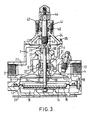
- FIGURE 3 is a section, to an enlarged scale, on the line 3-3 of Figure 1 showing the steam valve closed; and
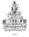
- FIGURE 4 is a section, similar to Figure 3, showing the steam valve open.
- Referring to the accompanying drawings, a
mixing valve 1 is shown comprising a body 2 havingseparate inlets - The body 2 has an internal partition 6 separating
respective inlet chambers water inlet chamber 8 through a plurality ofports 10. Theports 10 provide a permanently open connection between theinlet chamber 8 and mixing chamber 9 through which water can flow at all times. - The cold
water inlet chamber 8 is connected tocold water inlet 4 by a port 11 in the body 2 through which the flow rate is controlled by an adjustableflow restrictor valve 12 mounted in theinlet 4. Theinlet chamber 8 is defined in part by arolling edge diaphragm 13 supported at the centre on each side byrespective metal plates base plate 16 secured to the body 2 by threadedfasteners 17. Thediaphragm 13 is made of steam resistant fabric reinforced rubbber. - The
base plate 16 provides acontrol chamber 18 communicating with thecold water inlet 4 through apassageway 19 opening into theinlet 4 upstream of theflow restrictor valve 12. - Attached to the
base plate 16 byscrews 20 is asquare mounting plate 21 having ahole 22 at each corner for mounting thevalve 1 by means of threaded fasteners (not shown). - The
steam inlet chamber 7 is connected to thesteam inlet 3 by apassageway 23 in the body 2 and is defined in part by abonnet 24 secured to the body 2 by threadedfasteners 25. - Flow of steam from the
inlet chamber 7 to the mixing chamber 9 is controlled by apoppet valve 26 arranged in theinlet chamber 7 for axial movement relative to avalve seating member 27. Thepoppet valve 26 has ametal body 28 to which a PTFEface seating ring 29 is secured by ametal plug 30 pressed into thebody 28. - The
seating member 27 is made of stainless steel and opens to adiffuser 31 mounted within the mixing chamber 9. Thediffuser 31 is provided with a plurality ofradial ports 32 opening into the mixing chamber 9 opposite anintermediate wall 33 within the mixing chamber 9 which directs the cold water flow from theinlet chamber 8 past theports 32. - The
poppet valve 26 is coupled to thediaphragm 13 by apush rod 34 arranged for axial sliding movement through guide supports 35 in theseating member 27, acentral bore 36 in thediffuser 31 and aguide hole 37 in the partition 6. - The
diaphragm 13 is subjected on opposed sides to the water pressures in theinlet chamber 8 and thecontrol chamber 18. When there is no water flow, these pressures are balanced and thepoppet valve 26 engages theseating member 27 under the biassing of areturn spring 38 assisted by the hydrostatic steam pressure in theinlet chamber 7 to shut-off the steam flow as shown in Figure 3. - When there is water flow, a pressure drop occurs across the
flow restrictor valve 12 and the upstream and downstream pressures are transmitted to thecontrol chamber 18 and theinlet chamber 8 giving rise to a pressure differential across thediaphragm 13. The differential pressure increases with increase in the flow and generates a force which urges thediaphragm 13 and pushrod 34 in a direction to open thepoppet valve 26 against the biassing of thespring 38 allowing the steam to flow and mix with the cold water which is thereby heated. - By directing the cold water flow past the
steam ports 32, the steam is blended smoothly with the cold water and the volume of the mixing chamber 9 can be kept small. As a result thevalve 1 operates quietly without any noticeable succession of steam implosions. - For controlling the final water temperature, the
bonnet 24 mounts atemperature control spindle 3 sealed by agland 40 retained by acompression collar 41 secured to thebonnet 24 by threadedfasteners 42. - The inner end of the
spindle 39 provides a stop 43 to limit opening movement of thepoppet valve 26 and is axially adjustable between a first end position in which thepoppet valve 26 is held closed and a second end position permitting maximum opening of thepoppet valve 26 by a manuallyoperable control handle 4 connected to the outer end. - The
flow restrictor valve 12 is adjusted on initial installation of the valve I with the stop 43 in the second end position to set the maximum water temperature that can be obtained enabling the user to select any desired temperature up to the maximum by appropriate adjustment of the stop 43. - As will now be appreciated the present invention provides a valve for mixing steam with cold water in which valve means for controlling the steam flow is responsive to the cold water flow so as to shut-off the steam flow when the water flow is low or off. In this way the valve is flushed with cold water on stopping the flow thereby preventing a violent burst of steam being obtained when the flow is re-started.
- Additionally, if the cold water supply fail the steam flow is immediately shut-off by the poppet valve thereby preventing escape of steam and/or back-flow into the cold water supply. Similarly the poppet valve prevents back-flow of cold water into the steam supply. As a result the invented valve can be fitted without non-return valves in the steam and cold water supplies although it is generally preferable to include such non-return valves as a precaution in the event of the poppet valve failing.
- The valve may include a trim cover over the bonnet and body to prevent users touching the hot surfaces.
- The flow control valve for starting and stopping water flow through the invented valve may be connected to the outlet as described or to the cold water inlet and may also include means for adjusting the flow.
- The valve seating member may be integral with the diffuser, for example the valve seating member and diffuser may comprise a one piece stainless steel casting.
- The valve face seating ring may comprise poly- etheretherketone (PEEK) or any other suitable material in place of polytetrafluoroethylene (PTFE).
- The push rod connecting the diaphragm and valve member may be located against rotation, for example the guide hole in the partition may be of square of other non-circular cross-section in which a portion of the push rod of complementary cross-section is slidably received.
- A lockshield cover may be provided to prevent accidental or unauthorised adjustment of the set position of the flow restrictor valve.
- The control handle may be detachable and the compression collar provided with a lockshield to prevent accidental or unauthorised adjustment of the set position of the temperature control spindle.
- The grip portion of the control handle may be extended to facilitate handling.
Claims (8)
Applications Claiming Priority (2)
| Application Number | Priority Date | Filing Date | Title |
|---|---|---|---|
| GB8704395A GB2201487B (en) | 1987-02-25 | 1987-02-25 | Mixing valve |
| GB8704395 | 1987-02-25 |
Publications (2)
| Publication Number | Publication Date |
|---|---|
| EP0280482A1 EP0280482A1 (en) | 1988-08-31 |
| EP0280482B1 true EP0280482B1 (en) | 1990-08-22 |
Family
ID=10612900
Family Applications (1)
| Application Number | Title | Priority Date | Filing Date |
|---|---|---|---|
| EP88301458A Expired - Lifetime EP0280482B1 (en) | 1987-02-25 | 1988-02-22 | Mixing valve |
Country Status (8)
| Country | Link |
|---|---|
| US (1) | US4834130A (en) |
| EP (1) | EP0280482B1 (en) |
| JP (1) | JPS63225772A (en) |
| CA (1) | CA1286200C (en) |
| DE (1) | DE3860466D1 (en) |
| ES (1) | ES2017010B3 (en) |
| GB (1) | GB2201487B (en) |
| IE (1) | IE880234L (en) |
Cited By (1)
| Publication number | Priority date | Publication date | Assignee | Title |
|---|---|---|---|---|
| US7770807B2 (en) | 2006-03-29 | 2010-08-10 | Aqualisa Products Limited | Water valve assembly |
Families Citing this family (7)
| Publication number | Priority date | Publication date | Assignee | Title |
|---|---|---|---|---|
| JP2626752B2 (en) * | 1987-04-23 | 1997-07-02 | 株式会社 ミヤワキ | Mixing valve device |
| JP2632324B2 (en) * | 1987-10-13 | 1997-07-23 | 株式会社ミヤワキ | Mixing valve device |
| US5086089A (en) * | 1989-11-03 | 1992-02-04 | Mobil Oil Corporation | Programmed gelation of polymers using melamine resins |
| GB2270139A (en) * | 1992-08-24 | 1994-03-02 | Douglas Ind Sales Limited | Flow control for mixing valves |
| US5931181A (en) * | 1997-06-19 | 1999-08-03 | Emhart Inc. | Anti-scald faucet system |
| US7201181B1 (en) | 2004-12-07 | 2007-04-10 | Armstrong International, Inc. | Mixing valve |
| US20110089249A1 (en) * | 2009-10-21 | 2011-04-21 | Honeywell International Inc. | Thermostatic mixing valve with pressure reducing element |
Citations (1)
| Publication number | Priority date | Publication date | Assignee | Title |
|---|---|---|---|---|
| US3582229A (en) * | 1968-09-03 | 1971-06-01 | Troesch Hans A | Circulating pump for hot water heating system |
Family Cites Families (13)
| Publication number | Priority date | Publication date | Assignee | Title |
|---|---|---|---|---|
| GB356796A (en) * | 1930-06-10 | 1931-09-10 | United Water Softeners Ltd | Improvements relating to apparatus for supplying reagents under pressure |
| GB380723A (en) * | 1931-03-21 | 1932-09-22 | John Sidney Miller | Improved valve-apparatus for aerating liquids |
| US2335250A (en) * | 1942-06-20 | 1943-11-30 | Sarco Company Inc | Steam and water mixing device |
| US2644482A (en) * | 1944-11-13 | 1953-07-07 | Joy Mfg Co | Fluid flow regulator |
| US2483426A (en) * | 1945-09-21 | 1949-10-04 | Marlin C Moore | Steam injection water heater |
| GB690570A (en) * | 1950-08-05 | 1953-04-22 | Percy George Tacchi Junior | Improvements relating to cut-off valves for use with fluid mixing valves |
| GB824965A (en) * | 1955-11-14 | 1959-12-09 | Strahman Valves Inc | Hosing apparatus |
| GB808769A (en) * | 1956-01-12 | 1959-02-11 | Percy George Tacchi Senior | Improvements relating to valves for mixing fluids at different temperatures |
| US2903009A (en) * | 1956-01-12 | 1959-09-08 | Tacchi Percy George | Valves for mixing fluids at different temperatures |
| US3482229A (en) * | 1966-10-19 | 1969-12-02 | Photocircuits Corp | Tape system with extended speed range |
| GB1220586A (en) * | 1967-08-02 | 1971-01-27 | Meynell Valves Ltd Formerly Kn | Improved valve for mixing fluids in constant proportions |
| US3566902A (en) * | 1968-05-13 | 1971-03-02 | Leslie Co | Fluid flow system |
| EP0273988B1 (en) * | 1986-07-17 | 1992-05-20 | Miyawaki Incorporated | Mixing valve device |
-
1987
- 1987-02-25 GB GB8704395A patent/GB2201487B/en not_active Expired - Fee Related
-
1988
- 1988-01-28 IE IE880234A patent/IE880234L/en unknown
- 1988-02-03 CA CA000558075A patent/CA1286200C/en not_active Expired - Fee Related
- 1988-02-12 US US07/155,549 patent/US4834130A/en not_active Expired - Lifetime
- 1988-02-22 JP JP63039337A patent/JPS63225772A/en active Pending
- 1988-02-22 DE DE8888301458T patent/DE3860466D1/en not_active Expired - Fee Related
- 1988-02-22 EP EP88301458A patent/EP0280482B1/en not_active Expired - Lifetime
- 1988-02-22 ES ES88301458T patent/ES2017010B3/en not_active Expired - Lifetime
Patent Citations (1)
| Publication number | Priority date | Publication date | Assignee | Title |
|---|---|---|---|---|
| US3582229A (en) * | 1968-09-03 | 1971-06-01 | Troesch Hans A | Circulating pump for hot water heating system |
Cited By (1)
| Publication number | Priority date | Publication date | Assignee | Title |
|---|---|---|---|---|
| US7770807B2 (en) | 2006-03-29 | 2010-08-10 | Aqualisa Products Limited | Water valve assembly |
Also Published As
| Publication number | Publication date |
|---|---|
| IE880234L (en) | 1988-08-25 |
| ES2017010B3 (en) | 1990-12-16 |
| GB8704395D0 (en) | 1987-04-01 |
| GB2201487A (en) | 1988-09-01 |
| CA1286200C (en) | 1991-07-16 |
| JPS63225772A (en) | 1988-09-20 |
| US4834130A (en) | 1989-05-30 |
| EP0280482A1 (en) | 1988-08-31 |
| GB2201487B (en) | 1990-10-31 |
| DE3860466D1 (en) | 1990-09-27 |
Similar Documents
| Publication | Publication Date | Title |
|---|---|---|
| US5355906A (en) | Pressure balanced mixing valve | |
| US3929283A (en) | Thermostatic mixing apparatus and a related method for regulating temperature | |
| US5931181A (en) | Anti-scald faucet system | |
| US4217931A (en) | Adjustable check valve | |
| US7175100B2 (en) | Fail-safe proportional mixing valve | |
| EP1590715B1 (en) | Thermostatic mixer with flow diverting means | |
| US5356074A (en) | Thermostatic mixing device | |
| EP0280482B1 (en) | Mixing valve | |
| EP1190284B1 (en) | Thermostatic mixing valve | |
| US5884652A (en) | 2/3 handle pressure balancer system | |
| EP0880734B1 (en) | Flow control ports for a thermostatic mixing faucet | |
| US2966928A (en) | Fluid mixing devices | |
| US5518019A (en) | Diverter and volume control valve | |
| US6446655B1 (en) | Faucet assembly with independent controls for temperature and flow rate | |
| US4112959A (en) | Adjustable check valve | |
| US3828821A (en) | Pressure regulator faucet slide valve | |
| ITBS20010100A1 (en) | HOT AND COLD WATER MIXER TAP WITH THERMOSTATIC UNIT AND FLOW DIVERTER | |
| US3420272A (en) | Mixing valve | |
| US2607600A (en) | Temperature and volume control valve | |
| US7201181B1 (en) | Mixing valve | |
| US4896691A (en) | Pressure compensating device | |
| US2987076A (en) | Preset fluid control system | |
| US4306582A (en) | Mixing valve | |
| US3675682A (en) | Self-sealing mixture valve unit for single-handled sink or lavatory fixture | |
| US3753448A (en) | Valve assembly for water fountains and the like |
Legal Events
| Date | Code | Title | Description |
|---|---|---|---|
| PUAI | Public reference made under article 153(3) epc to a published international application that has entered the european phase |
Free format text: ORIGINAL CODE: 0009012 |
|
| AK | Designated contracting states |
Kind code of ref document: A1 Designated state(s): BE CH DE ES FR IT LI LU NL SE |
|
| 17P | Request for examination filed |
Effective date: 19881101 |
|
| 17Q | First examination report despatched |
Effective date: 19890822 |
|
| GRAA | (expected) grant |
Free format text: ORIGINAL CODE: 0009210 |
|
| AK | Designated contracting states |
Kind code of ref document: B1 Designated state(s): BE CH DE ES FR IT LI LU NL SE |
|
| PG25 | Lapsed in a contracting state [announced via postgrant information from national office to epo] |
Ref country code: SE Free format text: THE PATENT HAS BEEN ANNULLED BY A DECISION OF A NATIONAL AUTHORITY Effective date: 19900822 Ref country code: LI Effective date: 19900822 Ref country code: CH Effective date: 19900822 Ref country code: BE Effective date: 19900822 |
|
| REF | Corresponds to: |
Ref document number: 3860466 Country of ref document: DE Date of ref document: 19900927 |
|
| ET | Fr: translation filed | ||
| ITF | It: translation for a ep patent filed |
Owner name: STUDIO MASSARI S.R.L. |
|
| REG | Reference to a national code |
Ref country code: CH Ref legal event code: PL |
|
| PG25 | Lapsed in a contracting state [announced via postgrant information from national office to epo] |
Ref country code: LU Free format text: LAPSE BECAUSE OF NON-PAYMENT OF DUE FEES Effective date: 19910228 |
|
| PLBE | No opposition filed within time limit |
Free format text: ORIGINAL CODE: 0009261 |
|
| STAA | Information on the status of an ep patent application or granted ep patent |
Free format text: STATUS: NO OPPOSITION FILED WITHIN TIME LIMIT |
|
| 26N | No opposition filed | ||
| PGFP | Annual fee paid to national office [announced via postgrant information from national office to epo] |
Ref country code: FR Payment date: 19930201 Year of fee payment: 6 |
|
| PGFP | Annual fee paid to national office [announced via postgrant information from national office to epo] |
Ref country code: DE Payment date: 19930206 Year of fee payment: 6 |
|
| PGFP | Annual fee paid to national office [announced via postgrant information from national office to epo] |
Ref country code: ES Payment date: 19930208 Year of fee payment: 6 |
|
| ITTA | It: last paid annual fee | ||
| PGFP | Annual fee paid to national office [announced via postgrant information from national office to epo] |
Ref country code: NL Payment date: 19930228 Year of fee payment: 6 |
|
| PG25 | Lapsed in a contracting state [announced via postgrant information from national office to epo] |
Ref country code: ES Free format text: LAPSE BECAUSE OF NON-PAYMENT OF DUE FEES Effective date: 19940223 |
|
| PG25 | Lapsed in a contracting state [announced via postgrant information from national office to epo] |
Ref country code: NL Effective date: 19940901 |
|
| NLV4 | Nl: lapsed or anulled due to non-payment of the annual fee | ||
| PG25 | Lapsed in a contracting state [announced via postgrant information from national office to epo] |
Ref country code: FR Effective date: 19941031 |
|
| PG25 | Lapsed in a contracting state [announced via postgrant information from national office to epo] |
Ref country code: DE Effective date: 19941101 |
|
| REG | Reference to a national code |
Ref country code: FR Ref legal event code: ST |
|
| REG | Reference to a national code |
Ref country code: ES Ref legal event code: FD2A Effective date: 19990405 |
|
| PG25 | Lapsed in a contracting state [announced via postgrant information from national office to epo] |
Ref country code: IT Free format text: LAPSE BECAUSE OF NON-PAYMENT OF DUE FEES;WARNING: LAPSES OF ITALIAN PATENTS WITH EFFECTIVE DATE BEFORE 2007 MAY HAVE OCCURRED AT ANY TIME BEFORE 2007. THE CORRECT EFFECTIVE DATE MAY BE DIFFERENT FROM THE ONE RECORDED. Effective date: 20050222 |