EP0280104B1 - Mechanical drum counter - Google Patents
Mechanical drum counter Download PDFInfo
- Publication number
- EP0280104B1 EP0280104B1 EP88101772A EP88101772A EP0280104B1 EP 0280104 B1 EP0280104 B1 EP 0280104B1 EP 88101772 A EP88101772 A EP 88101772A EP 88101772 A EP88101772 A EP 88101772A EP 0280104 B1 EP0280104 B1 EP 0280104B1
- Authority
- EP
- European Patent Office
- Prior art keywords
- switching
- magnet
- rocker
- counting device
- drum
- Prior art date
- Legal status (The legal status is an assumption and is not a legal conclusion. Google has not performed a legal analysis and makes no representation as to the accuracy of the status listed.)
- Expired - Lifetime
Links
Images
Classifications
-
- G—PHYSICS
- G06—COMPUTING; CALCULATING OR COUNTING
- G06M—COUNTING MECHANISMS; COUNTING OF OBJECTS NOT OTHERWISE PROVIDED FOR
- G06M1/00—Design features of general application
- G06M1/08—Design features of general application for actuating the drive
- G06M1/10—Design features of general application for actuating the drive by electric or magnetic means
- G06M1/102—Design features of general application for actuating the drive by electric or magnetic means by magnetic or electromagnetic means
Definitions
- the invention relates to a mechanical roller counter with a ratchet mechanism on the ratchet wheel for the initial roller and incrementing the number rollers according to the preamble of claim 1.
- Roller counters with mechanical or electromechanical drive are known. These are used to record quantities, parts, quantities, lengths or movements.
- the output force for the display rollers is transmitted via shafts, levers, gears and the like.
- Mechanical components In the known electromechanical counters, the driving force is supplied in the form of electrical energy and converted into mechanical energy in the counter for actuating the number rollers, e.g. according to DE-PS 35 11 870, DE-GM 83 30 263 and DE-GM 19 35 240.
- the invention has for its object to provide a particularly reliable and inexpensive counter with a low overall height, which can be used on site even in extremely unfavorable conditions, such as in plant construction and in hydraulically operated machines is to be driven without contact without electrical connections or electrical energy supply.
- the counter according to the preamble of claim 1 is characterized in that the rocker carries a permanent magnet on at least one side and is preferably held in the rest position under the action of a holding magnet or ferromagnetic part and / or a spring, such that when approaching of a ferromagnetic or magnetic switching part, the coil-free magnetic rocker tilts while advancing the ratchet wheel and thereby causes the counting without supplying electrical energy.
- a rocker can be used with permanent magnets on one side and counterweight on the other, as well as a return spring and ferromagnetic switching part or, as preferably described below, the rocker can accommodate permanent magnets on both sides and interact with a ferromagnetic holding and a magnetic switching part.
- the drive takes place via permanent magnetic fields which do not react negatively to environmental influences such as dirt, liquids, gases, light, noise and vibrations.
- the permanent magnets are preferably hermetically sealed, the switching part being located, for example, on the piston of a pneumatic cylinder made of non-magnetic material. The material selection from the counter and the auxiliary devices must be coordinated with the magnetic functions.
- a permanent magnet with an opposite pole arrangement can be provided on both sides symmetrically to the axis of rotation, such that when a switching magnet arranged outside the counter approaches, the one permanent magnet is attracted and the other is repelled, whereby an increased switching force is achieved.
- the housing 1 serves to accommodate and store the set of rollers, consisting of number rollers 2 with indexing drives 3 and star wheel 4 for the initial roller and the two parallel shafts 5 and 6, and the two end plates 7 and 8.
- the shaft 9 supports the magnetic rocker 10 with the two to this (10) symmetrically arranged permanent magnets 11 and 12.
- the rocker 10 is held in the rest position by the shaft 6 as a ferromagnetic part.
- the pawl 13 engages in the switching star 4.
- the magnetic rocker 10 When the switching magnet 14 approaches, the magnetic rocker 10 is tilted in accordance with FIG. 2 due to the torque which increases counterclockwise compared to the holding torque.
- the first half step for switching on is effected by means of the switching pawl 15, while the second switching step occurs when the rocker 10 is tilted back in Rest position when the switching magnet 14 is removed, which means that the starting position for the next sequence of movements is reached.
- a magnetic yoke 16 can furthermore reduce scatter losses which occur and thus serve to strengthen the magnetic field in the working area.
- FIG. 3 shows a top view of the open counter and FIG. 4 shows a side view
- FIG. 5 shows a partial section through the pneumatic drive.
- the bearing of the roller set 2 to 6 between the plates 7 and 8 with the ends of the shafts 5 and 6 in the perforation 17 and the slot 18 in the housing 1 can be seen.
- the shoulder 19 running in the direction of the rocker 10 with bar 20 on the housing 1 can be seen, which serves to fix the counter on the pneumatic cylinder 21 by means of anti-magnetic strips 22.
- the switching magnet 14 for actuating the counter on the piston 23 is arranged between the seals 24.
Abstract
Description
Die Erfindung bezieht sich auf ein mechanisches Rollenzählwerk mit Klinkenschaltung am Schaltrad zur Anfangsrolle und Fortschaltung der Ziffernrollen nach dem Oberbegriff des Anspruchs 1.The invention relates to a mechanical roller counter with a ratchet mechanism on the ratchet wheel for the initial roller and incrementing the number rollers according to the preamble of
Es sind Rollenzählwerke mit mechanischem bzw. elektromechanischem Antrieb bekannt. Diese werden zur Erfassung von Stückzahlen, Teilen, Mengen, Längen oder Bewegungsabläufen eingesetzt. Hierbei wird die Abtriebskraft für die Anzeigerollen über Wellen, Hebel, Zahnräder und dgl. mechanische Bauteile übertragen. Bei den bekannten elektromechanischen Zählwerken wird die Antriebskraft in Form von elektrischer Energie zugeführt und im Zählwerk in mechanische Energie zur Betätigung der Zahlenrollen umgesetzt, z.B. nach DE-PS 35 11 870, DE-GM 83 30 263 und DE-GM 19 35 240.Roller counters with mechanical or electromechanical drive are known. These are used to record quantities, parts, quantities, lengths or movements. The output force for the display rollers is transmitted via shafts, levers, gears and the like. Mechanical components. In the known electromechanical counters, the driving force is supplied in the form of electrical energy and converted into mechanical energy in the counter for actuating the number rollers, e.g. according to DE-PS 35 11 870, DE-GM 83 30 263 and DE-GM 19 35 240.
Im rauhen und schmutzigen Betrieb, sowie bei aggessiver oder explosionsgefährdeter Atmosphäre sind hierbei besondere Dicht- und Sicherheitsvorkehrungen zu treffen, un einen zuverlässigen Betrieb zu gewährleisten. Soll mit elektromechanischem Zählen vor Ort gearbeitet werden, so müssen Impulsgeber, Zähler und Stromversorgung installiert werden.In rough and dirty operation, as well as in aggressive or potentially explosive atmospheres, special sealing and safety precautions must be taken to ensure reliable operation. If you want to work with electromechanical counting on site, pulse generator, counter and power supply must be installed.
Der Erfindung liegt die Aufgabe zugrunde, ein besonders zuverlässiges und preisgünstiges Zählwerk mit geringer Bauhöhe zu schaffen, welches auch bei extrem ungünstigen Bedingungen, wie im Anlagebau und bei hydraulisch betriebenen Maschinen, am Ort eingesetzt werden kann und ohne elektrische Anschlüsse bzw. elektrische Energiezufur berührungslos anzutreiben ist.The invention has for its object to provide a particularly reliable and inexpensive counter with a low overall height, which can be used on site even in extremely unfavorable conditions, such as in plant construction and in hydraulically operated machines is to be driven without contact without electrical connections or electrical energy supply.
Zur Lösung dieser Aufgabe kennzeichnet sich das Zählwerk nach dem Oberbegriff des Anspruchs 1 dadurch, daß die Wippe wenigstens an einer Seite einen Dauermagneten trägt und in Ruhestellung vorzugsweise unter Wirkung eines Haltemagnet- oder Ferromagnetteils und/oder einer Feder gehalten ist, derart, daß bei Annäherung eines ferromagnetischen oder magnetischen Schaltteils die Spulenfreie Magnetwippe unter Fortschaltung des Schaltrads kippt und dabei die Weiterzählung ohne Zufuhr elektrischer Energie bewirkt.To solve this problem, the counter according to the preamble of
So kann beispielsweise eine Wippe Verwendung finden mit Dauermagneten auf einer Seite und Gegengewicht auf der anderen Seite, sowie Rückholfeder und ferromagnetischem Schaltteil oder wie im folgenden vorzugsweise beschrieben, kann die Wippe beidseits Dauermagneten aufnehmen und mit einem ferromagnetischen Halte-und einem magnetischen Schaltteil zusammenwirken.For example, a rocker can be used with permanent magnets on one side and counterweight on the other, as well as a return spring and ferromagnetic switching part or, as preferably described below, the rocker can accommodate permanent magnets on both sides and interact with a ferromagnetic holding and a magnetic switching part.
Damit erfolgt gemäß der Erfindung der Antrieb über Permanentmagnetfelder, welche auf Umwelteinflüsse wie Schmutz, Flüssigkeiten, Gase, Licht, Lärm und Schwingungen nicht negativ reagieren. Die Permanentmagnete sind vorzugsweise hermetisch abgeschlossen, wobei sich der Schaltteil, z.B. am Kolben eines Pneumatikzylinders aus nicht magnetischen Material befindet. Die Materialauswahl vom Zählwerk und der Hilfseinrichtungen sind auf die magnetischen Funktionen abzustimmen.Thus, according to the invention, the drive takes place via permanent magnetic fields which do not react negatively to environmental influences such as dirt, liquids, gases, light, noise and vibrations. The permanent magnets are preferably hermetically sealed, the switching part being located, for example, on the piston of a pneumatic cylinder made of non-magnetic material. The material selection from the counter and the auxiliary devices must be coordinated with the magnetic functions.
Die Verwendung von Sensoren, Hilfsenergien oder mechanischen Übertragungsglieder vom Zählobjekt zum Zahler ist nicht erforderlich.The use of sensors, auxiliary energy or mechanical transmission elements from the counter object to the payer is not necessary.
Nach einem weiteren Gedanken der Erfindung kann beidseits symmetrisch zu Drehachse je ein Permanentmagnet mit gegenpoliger Anordnung vorgesehen sein, derart, daß bei Annäherung eines außerhalb vom Zähler angeordneten Schaltmagneten der eine Permanentmagnet angezogen und der andere abgestoßen wird, wodurch eine erhöhte Schaltkraft erreicht wird.According to a further idea of the invention, a permanent magnet with an opposite pole arrangement can be provided on both sides symmetrically to the axis of rotation, such that when a switching magnet arranged outside the counter approaches, the one permanent magnet is attracted and the other is repelled, whereby an increased switching force is achieved.
Ein weiterer Vorteil gegenüber bekannten Zählwerken wird erreicht, wenn anstelle einer herkömmlichen Rückzugfeder ein Magnet die Funktion derselben übernimmt. Bei der Rückzugfeder ist in der Ruhestellung das Haltemoment am kleinsten und steigt während dem ersten Halbschritt an, wobei diese Kraft für die Beschleunigung der Rollen verloren geht. Beim zweiten Halbschritt ist die Kraft während des Leerweges am größten und wird am kleinsten, wenn die Rollen wieder weitergeschaltet werden sollen. Diese Kraft-Weg-Verhältnisse sind beim erfindungsgemäßen rein magnetischen Antrieb umgekehrt und wirken sich somit auf die Weiterschaltung der Rollen positiv aus. Das Zählwerk kann dabei addierend oder subtrahierend ausgelegt sein.Another advantage over known counters is achieved if a magnet takes over the function of the same instead of a conventional return spring. With the return spring, the holding torque is smallest in the rest position and increases during the first half step, this force being lost for the acceleration of the rollers. In the second half step, the force is greatest during the free travel and becomes the smallest when the rollers are to be switched on again. In the purely magnetic drive according to the invention, these force-displacement relationships are reversed and thus have a positive effect on the switching of the roles. The counter can be designed to add or subtract.
Eine bevorzugte Ausführungsform eines Rollenzählwerk gemäß der Erfindung ist beispielsweise in der Zeichnung dargestellt und nachfolgend beschrieben und zwar zeigen:
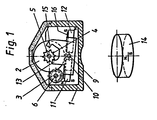
Figur 1 und 2- einen Querschnitt durch das Zählwerk in Ruhe- und Arbeitsstellung nach dem ersten Halbschritt,
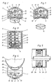
Figur 3- eine Draufsicht auf das offene Zählwerk,
Figur 4- eine Seitenansicht auf das Zählwerk und seine Befestigung am Pneumatikzylinder,
Figur 5- eine Teilansicht des Pneumatikzylinders und Schaltmagnet.
- Figure 1 and 2
- a cross section through the counter in the rest and working position after the first half step,
- Figure 3
- a plan view of the open counter,
- Figure 4
- a side view of the counter and its attachment to the pneumatic cylinder,
- Figure 5
- a partial view of the pneumatic cylinder and switching magnet.
Das Gehäuse 1 dient der Aufnahme und Lagerung des Rollensatzes, bestehend aus Zahlenrollen 2 mit Fortschalttrieben 3 und Schaltstern 4 zur Anfangsrolle und den beiden parallelen Wellen 5 und 6, sowei den beiden Endplatinen 7 und 8. Die Welle 9 lagert die Magnetwippe 10 mit den beidseits zu dieser (10) symmetrisch angeordneten Dauermagneten 11 und 12. Bei Fig. 1 steht die Wippe 10 in Ruhestellung gehalten durch die Welle 6 als Ferromagnetteil. Hierbei greift die Schaltklinke 13 in den Schaltstern 4.The
Bei Annäherung des Schaltmagneten 14 erfolgt eine Kippung der Magnetwippe 10 entsprechend Figur 2 zufolge des dem Uhrzeigersinn entgegengesetzt größer werdenden Drehmoment gegenüber dem Haltemoment. Hierbei wird unter Vermittlung der Schaltklinke 15 der erste Halbschritt zu Weiterschaltung bewirkt, während der zweite Schaltschritt beim Rückkippen der Wippe 10 in Ruhestellung bei Entfernung des Schaltmagneten 14 erfolgt, womit die Ausgangslage für den nächsten Bewegungsablauf erreicht ist. Bei Anordnung von zwei Dauermagneten 11 und 12 kann überdies ein Magnetjoch 16 auftretende Streuverluste verringern und damit einer Verstärkung des Magnetfelds im Arbeitsbereich dienen.When the
In Figur 3 ist schließlich eine Draufsicht des offenen Zählwerks gezeigt und in Fig. 4 eine Seitenansicht, sowie in Figur 5 ein Teilschnitt durch den Pneumatikantrieb. Hieraus wird die Lagerung des Rollensatzes 2 bis 6 zwischen den Platinen 7 und 8 mit den Enden der Wellen 5 und 6 in der Lochung 17 und der Schlitzung 18 im Gehäuse 1 ersichtlich. Desweiteren wird der in Richtung der Wippe 10 verlaufende Absatz 19 mit Leiste 20 am Gehäuse 1 ersichtlich, welche der Festlegung des Zählwerks am Pneumatikzylinder 21 mittels antimagnetischer Bänder 22 dient. Hierbei wird der Schaltmagnet 14 zur Betätigung des Zählwerks am Kolben 23 zwischen den Dichtungen 24 angeordnet.Finally, FIG. 3 shows a top view of the open counter and FIG. 4 shows a side view, and FIG. 5 shows a partial section through the pneumatic drive. From this, the bearing of the roller set 2 to 6 between the
Claims (8)
- Mechanical drum-type counting device having a latch drive (10, 13, 15) on the switching drum (4) to the starting drum and means for continuously switching the digit figure drums (2), the drive of the switching latches (13, 15) being carried out by means of a tiltable rocker (10), characterized in that the rocker (10) carries a permanent magnet (11, 12) on at least one side and is retained in its resting position preferably under the effect of a holding magnet or ferromagnet portion (6) and/or a spring such that during the approximation of a ferromagnetic or magnetic switching portion (14) the coil-free magnet rocker (10) tilts while switching the switching drum (4), at the same time effecting the advance counting without any supply of electric energy.
- Mechanical drum-type counting device according to Claim 1, characterized in that a permanent magnet (11, 12) with opposite polarization is provided symmetrically on eiher side of the rotation axis (9) such that during the approximation of a switching magnet (14) arranged externally of the counter one permanent magnet (11) is attracted and the other one (12) repulsed.
- Mechanical drum-type counting device according to Claim 1 or 2, characterized in that the permanent magnets (11, 12) are arranged symmetrically to the bearing axis (9) of the magnet rocker (10).
- Mechanical drum-type counting device according to any one of Claims 1 to 3, characterized in that the short switching latches (13, 15) are integrally moulded onto the magnet rocker (10) and the magnet rocker (10) is retained in its resting position by attracting a magnet to the shaft (6).
- Mechanical drum-type counting device according to any one of Claims 2 to 4, characterized in that the permanent magnets (11, 12) are magnetically connected via a magnetic yoke (16).
- Mechanical drum-type counting device according to any one of the preceding claims, characterized in that the pre-fabricated set of drums (2 to 6) retained between two plates (7, 8) can be inserted into a hermetically sealed housing (1) as an assembly consisting of digit figure drums (2), continuous switching drives (3) and magnet drive (6) without any service connections.
- Mechanical drum-type counting device according to Claim 6, characterized in that a shoulder (19) having a strip (20) extending on the housing towards the rocker (10) is used for fixing the counting device to the corresponding machine part (21) by means of anti-magnetic straps.
- Mechanical drum-type counting device according to any one of the preceding claims, characterized in that the switching magnet (14) is assigned to a moving part such as a piston (23) of an engine for counting the amount of strokes or the like.
Priority Applications (1)
| Application Number | Priority Date | Filing Date | Title |
|---|---|---|---|
| AT88101772T ATE77501T1 (en) | 1987-02-25 | 1988-02-08 | MECHANICAL ROLLER COUNTER. |
Applications Claiming Priority (2)
| Application Number | Priority Date | Filing Date | Title |
|---|---|---|---|
| DE19873705962 DE3705962A1 (en) | 1987-02-25 | 1987-02-25 | MECHANICAL ROLL COUNTER |
| DE3705962 | 1987-02-25 |
Publications (3)
| Publication Number | Publication Date |
|---|---|
| EP0280104A2 EP0280104A2 (en) | 1988-08-31 |
| EP0280104A3 EP0280104A3 (en) | 1989-09-20 |
| EP0280104B1 true EP0280104B1 (en) | 1992-06-17 |
Family
ID=6321691
Family Applications (1)
| Application Number | Title | Priority Date | Filing Date |
|---|---|---|---|
| EP88101772A Expired - Lifetime EP0280104B1 (en) | 1987-02-25 | 1988-02-08 | Mechanical drum counter |
Country Status (3)
| Country | Link |
|---|---|
| EP (1) | EP0280104B1 (en) |
| AT (1) | ATE77501T1 (en) |
| DE (2) | DE3705962A1 (en) |
Cited By (13)
| Publication number | Priority date | Publication date | Assignee | Title |
|---|---|---|---|---|
| US6561384B2 (en) | 1998-01-16 | 2003-05-13 | 1263152 Ontario Inc. | Medicament dispensing device and method for the use thereof |
| US6729330B2 (en) | 1998-05-05 | 2004-05-04 | Trudell Medical International | Indicating device for aerosol container |
| US6745760B2 (en) | 2001-05-15 | 2004-06-08 | Trudell Medical International | Medicament applicator |
| US6761161B2 (en) | 1998-05-05 | 2004-07-13 | Trudell Medical International | Indicating device |
| US7743945B2 (en) | 2005-01-20 | 2010-06-29 | Trudell Medical International | Dispensing device |
| US8074594B2 (en) | 2003-12-15 | 2011-12-13 | Trudell Medical International | Dose indicating device |
| US8079362B2 (en) | 2004-09-20 | 2011-12-20 | Trudell Medical International | Method for displaying dosage indicia |
| US8082873B2 (en) | 2008-05-05 | 2011-12-27 | Trudell Medical International | Drive mechanism for an indicating device |
| US8141550B2 (en) | 2006-08-01 | 2012-03-27 | Trudell Medical International | Dispensing device |
| US8181591B1 (en) | 2008-05-23 | 2012-05-22 | Trudell Medical International | Domed actuator for indicating device |
| US8327847B2 (en) | 2002-03-21 | 2012-12-11 | Trudell Medical International | Indicating device for aerosol container |
| US8578934B2 (en) | 2003-10-28 | 2013-11-12 | Trudell Medical International | Indicating device with warning dosage indicator |
| US8596265B2 (en) | 2008-10-22 | 2013-12-03 | Trudell Medical International | Modular aerosol delivery system |
Families Citing this family (1)
| Publication number | Priority date | Publication date | Assignee | Title |
|---|---|---|---|---|
| TW533865U (en) | 1997-06-10 | 2003-05-21 | Glaxo Group Ltd | Dispenser for dispensing medicament and actuation indicating device |
Family Cites Families (5)
| Publication number | Priority date | Publication date | Assignee | Title |
|---|---|---|---|---|
| DE1935240U (en) * | 1963-01-23 | 1966-03-24 | Hengstler K G Zaehlerfabrik J | ELECTRO-MECHANICAL PULSE COUNTER WITH ANCHOR GEAR AND SPRING TRANSMISSION. |
| CH444761A (en) * | 1965-12-10 | 1968-02-29 | Ebauches Sa | Magnetic drive device for watchmaking |
| DE1954623B2 (en) * | 1969-10-30 | 1973-02-15 | Siemens AG, 1000 Berlin u 8000 München | DIGITAL PLACERS USING MAGNETIC FIELD-DEPENDENT RESISTORS |
| AT377110B (en) * | 1981-10-29 | 1985-02-11 | Mattig Kg Anton | ELECTROMECHANICAL COUNTER |
| DE3511870C1 (en) * | 1985-04-01 | 1986-06-26 | J. Hengstler Kg, 7209 Aldingen | Pulse counters as electromechanical counters with voice coil drives |
-
1987
- 1987-02-25 DE DE19873705962 patent/DE3705962A1/en active Granted
-
1988
- 1988-02-08 DE DE8888101772T patent/DE3871981D1/en not_active Expired - Fee Related
- 1988-02-08 AT AT88101772T patent/ATE77501T1/en not_active IP Right Cessation
- 1988-02-08 EP EP88101772A patent/EP0280104B1/en not_active Expired - Lifetime
Cited By (32)
| Publication number | Priority date | Publication date | Assignee | Title |
|---|---|---|---|---|
| US7984826B2 (en) | 1998-01-16 | 2011-07-26 | Trudell Medical International | Indicating device |
| US6561384B2 (en) | 1998-01-16 | 2003-05-13 | 1263152 Ontario Inc. | Medicament dispensing device and method for the use thereof |
| US8505773B2 (en) | 1998-01-16 | 2013-08-13 | Trudell Medical International | Indicating device |
| US8157128B2 (en) | 1998-01-16 | 2012-04-17 | Trudell Medical International | Indicating device |
| US8944285B2 (en) | 1998-01-16 | 2015-02-03 | Trudell Medical International | Indicating device |
| US9649455B2 (en) | 1998-01-16 | 2017-05-16 | Trudell Medical International | Indicating device |
| US6761161B2 (en) | 1998-05-05 | 2004-07-13 | Trudell Medical International | Indicating device |
| US9168343B2 (en) | 1998-05-05 | 2015-10-27 | Trudell Medical International | Dispensing device |
| US7757688B2 (en) | 1998-05-05 | 2010-07-20 | Trudell Medical International | Dispensing device |
| US7650883B2 (en) | 1998-05-05 | 2010-01-26 | Trudell Medical International | Dispensing device |
| US8074643B2 (en) | 1998-05-05 | 2011-12-13 | Trudell Medical International | Dispensing device |
| US8662075B2 (en) | 1998-05-05 | 2014-03-04 | Trudell Medical International | Dispensing device |
| US6729330B2 (en) | 1998-05-05 | 2004-05-04 | Trudell Medical International | Indicating device for aerosol container |
| US6745760B2 (en) | 2001-05-15 | 2004-06-08 | Trudell Medical International | Medicament applicator |
| US8327847B2 (en) | 2002-03-21 | 2012-12-11 | Trudell Medical International | Indicating device for aerosol container |
| US9968748B2 (en) | 2003-10-28 | 2018-05-15 | Trudell Medical International | Indicating device with warning dosage indicator |
| US8578934B2 (en) | 2003-10-28 | 2013-11-12 | Trudell Medical International | Indicating device with warning dosage indicator |
| US8869735B2 (en) | 2003-12-15 | 2014-10-28 | Trudell Medical International, Inc. | Dose indicating device |
| US8074594B2 (en) | 2003-12-15 | 2011-12-13 | Trudell Medical International | Dose indicating device |
| US8079362B2 (en) | 2004-09-20 | 2011-12-20 | Trudell Medical International | Method for displaying dosage indicia |
| US7886934B2 (en) | 2005-01-20 | 2011-02-15 | Trudell Medical International | Dispensing device |
| US9656032B2 (en) | 2005-01-20 | 2017-05-23 | Trudell Medical International | Dispensing device |
| US7743945B2 (en) | 2005-01-20 | 2010-06-29 | Trudell Medical International | Dispensing device |
| US8973784B2 (en) | 2005-01-20 | 2015-03-10 | Trudell Medical International | Dispensing device |
| US9265901B2 (en) | 2006-08-01 | 2016-02-23 | Trudell Medical International | Dispensing device |
| US8141550B2 (en) | 2006-08-01 | 2012-03-27 | Trudell Medical International | Dispensing device |
| US10950149B2 (en) | 2006-08-01 | 2021-03-16 | Trudell Medical International | Dispensing device |
| US8082873B2 (en) | 2008-05-05 | 2011-12-27 | Trudell Medical International | Drive mechanism for an indicating device |
| US8181591B1 (en) | 2008-05-23 | 2012-05-22 | Trudell Medical International | Domed actuator for indicating device |
| US9032953B2 (en) | 2008-10-22 | 2015-05-19 | Trudell Medical International | Modular aerosol delivery system |
| US9242057B2 (en) | 2008-10-22 | 2016-01-26 | Trudell Medical International | Modular aerosol delivery system |
| US8596265B2 (en) | 2008-10-22 | 2013-12-03 | Trudell Medical International | Modular aerosol delivery system |
Also Published As
| Publication number | Publication date |
|---|---|
| EP0280104A2 (en) | 1988-08-31 |
| DE3705962A1 (en) | 1988-09-08 |
| EP0280104A3 (en) | 1989-09-20 |
| ATE77501T1 (en) | 1992-07-15 |
| DE3705962C2 (en) | 1988-12-01 |
| DE3871981D1 (en) | 1992-07-23 |
Similar Documents
| Publication | Publication Date | Title |
|---|---|---|
| EP0280104B1 (en) | Mechanical drum counter | |
| DE971059C (en) | Electric clock | |
| DE10007968C1 (en) | Mechanical shaft with integrated magnet arrangement | |
| EP2088264B1 (en) | Apparatus for actuating a locking element with an electrical generator | |
| DE3301222C2 (en) | Pendulum device | |
| DE718353C (en) | Interrupter to control the excitation current for magneto-electric machines | |
| DE102008043136A1 (en) | Linear motor driven hammer, has drive device with stator coils to move hitter by magnetic field to transfer impulse to anvil, where hitter produces own magnetic field by mutually opposite magnetic poles | |
| DE102004055626B3 (en) | Device for detecting movements and / or positions of an object | |
| EP0078787B1 (en) | Electromechanical counter for continuous numerical adding or substracting | |
| DE2903817A1 (en) | Electromagnetic pump for fluids - has pumping piston fixed to magnetic armature driven by linear motor outside paramagnetic casing of pump | |
| EP0196581B1 (en) | Pulse counter in the form of an electro-mechanical counter with an oscillating coil drive | |
| DE19504641A1 (en) | Linear actuators, useful esp. for moving knitting machines needles | |
| DE3103744A1 (en) | DISPLAY DEVICE FOR THE DISTANCE MEASUREMENT OF VEHICLES | |
| DE2757594A1 (en) | Electromagnetic pump for liquids and gases - has piston reciprocating in paramagnetic non-conducting cylinder surrounded by linear motor stator | |
| CH363078A (en) | DC machine based on the magnetic motor principle with a rotor made of permanent magnet material | |
| DE113403C (en) | ||
| DE102016115053A1 (en) | Electrical energy storage device and electrical appliance | |
| DE974497C (en) | Device for generating oscillating or shaking movements | |
| DE957529C (en) | Electric pulse counter | |
| DE628994C (en) | Electric oscillating armature motor | |
| DE923734C (en) | Electrical device for generating a rotary or orbital movement by means of successive current pulses in alternating directions | |
| DE3409182A1 (en) | Magnetic drive system | |
| DE2051764A1 (en) | Arrangement for converting a reciprocating movement of a first apparatus part into a step-by-step rotational movement in a specific direction of rotation of a second apparatus part | |
| EP3855608A1 (en) | Converter for converting mechanical energy into electrical energy | |
| DE479335C (en) | Vibrating or oscillating, electrical machine with constant air gap for power transmission |
Legal Events
| Date | Code | Title | Description |
|---|---|---|---|
| PUAI | Public reference made under article 153(3) epc to a published international application that has entered the european phase |
Free format text: ORIGINAL CODE: 0009012 |
|
| AK | Designated contracting states |
Kind code of ref document: A2 Designated state(s): AT BE CH DE ES FR GB GR IT LI NL |
|
| PUAL | Search report despatched |
Free format text: ORIGINAL CODE: 0009013 |
|
| AK | Designated contracting states |
Kind code of ref document: A3 Designated state(s): AT BE CH DE ES FR GB GR IT LI NL |
|
| 17P | Request for examination filed |
Effective date: 19891012 |
|
| 17Q | First examination report despatched |
Effective date: 19911104 |
|
| GRAA | (expected) grant |
Free format text: ORIGINAL CODE: 0009210 |
|
| AK | Designated contracting states |
Kind code of ref document: B1 Designated state(s): AT BE CH DE ES FR GB GR IT LI NL |
|
| PG25 | Lapsed in a contracting state [announced via postgrant information from national office to epo] |
Ref country code: IT Free format text: LAPSE BECAUSE OF FAILURE TO SUBMIT A TRANSLATION OF THE DESCRIPTION OR TO PAY THE FEE WITHIN THE PRE;WARNING: LAPSES OF ITALIAN PATENTS WITH EFFECTIVE DATE BEFORE 2007 MAY HAVE OCCURRED AT ANY TIME BEFORE 2007. THE CORRECT EFFECTIVE DATE MAY BE DIFFERENT FROM THE ONE RECORDED.SCRIBED TIME-LIMIT Effective date: 19920617 Ref country code: ES Free format text: THE PATENT HAS BEEN ANNULLED BY A DECISION OF A NATIONAL AUTHORITY Effective date: 19920617 Ref country code: BE Effective date: 19920617 Ref country code: GR Free format text: LAPSE BECAUSE OF FAILURE TO SUBMIT A TRANSLATION OF THE DESCRIPTION OR TO PAY THE FEE WITHIN THE PRESCRIBED TIME-LIMIT Effective date: 19920617 Ref country code: NL Effective date: 19920617 |
|
| REF | Corresponds to: |
Ref document number: 77501 Country of ref document: AT Date of ref document: 19920715 Kind code of ref document: T |
|
| REF | Corresponds to: |
Ref document number: 3871981 Country of ref document: DE Date of ref document: 19920723 |
|
| ET | Fr: translation filed | ||
| GBT | Gb: translation of ep patent filed (gb section 77(6)(a)/1977) | ||
| NLV1 | Nl: lapsed or annulled due to failure to fulfill the requirements of art. 29p and 29m of the patents act | ||
| PGFP | Annual fee paid to national office [announced via postgrant information from national office to epo] |
Ref country code: GB Payment date: 19930204 Year of fee payment: 6 |
|
| PLBE | No opposition filed within time limit |
Free format text: ORIGINAL CODE: 0009261 |
|
| STAA | Information on the status of an ep patent application or granted ep patent |
Free format text: STATUS: NO OPPOSITION FILED WITHIN TIME LIMIT |
|
| 26N | No opposition filed | ||
| PG25 | Lapsed in a contracting state [announced via postgrant information from national office to epo] |
Ref country code: GB Effective date: 19940208 |
|
| GBPC | Gb: european patent ceased through non-payment of renewal fee |
Effective date: 19940208 |
|
| PGFP | Annual fee paid to national office [announced via postgrant information from national office to epo] |
Ref country code: AT Payment date: 19950203 Year of fee payment: 8 |
|
| PGFP | Annual fee paid to national office [announced via postgrant information from national office to epo] |
Ref country code: CH Payment date: 19950223 Year of fee payment: 8 |
|
| PG25 | Lapsed in a contracting state [announced via postgrant information from national office to epo] |
Ref country code: AT Effective date: 19960208 |
|
| PGFP | Annual fee paid to national office [announced via postgrant information from national office to epo] |
Ref country code: FR Payment date: 19960222 Year of fee payment: 9 |
|
| PG25 | Lapsed in a contracting state [announced via postgrant information from national office to epo] |
Ref country code: LI Effective date: 19960229 Ref country code: CH Effective date: 19960229 |
|
| REG | Reference to a national code |
Ref country code: CH Ref legal event code: PL |
|
| PG25 | Lapsed in a contracting state [announced via postgrant information from national office to epo] |
Ref country code: FR Effective date: 19971030 |
|
| REG | Reference to a national code |
Ref country code: FR Ref legal event code: ST |
|
| PGFP | Annual fee paid to national office [announced via postgrant information from national office to epo] |
Ref country code: DE Payment date: 20060830 Year of fee payment: 19 |
|
| PG25 | Lapsed in a contracting state [announced via postgrant information from national office to epo] |
Ref country code: DE Free format text: LAPSE BECAUSE OF NON-PAYMENT OF DUE FEES Effective date: 20070901 |