EP0278769A2 - Papermakers fabric - Google Patents
Papermakers fabric Download PDFInfo
- Publication number
- EP0278769A2 EP0278769A2 EP88301172A EP88301172A EP0278769A2 EP 0278769 A2 EP0278769 A2 EP 0278769A2 EP 88301172 A EP88301172 A EP 88301172A EP 88301172 A EP88301172 A EP 88301172A EP 0278769 A2 EP0278769 A2 EP 0278769A2
- Authority
- EP
- European Patent Office
- Prior art keywords
- yarns
- fabric
- load
- machine direction
- control
- Prior art date
- Legal status (The legal status is an assumption and is not a legal conclusion. Google has not performed a legal analysis and makes no representation as to the accuracy of the status listed.)
- Ceased
Links
Images


Classifications
-
- D—TEXTILES; PAPER
- D21—PAPER-MAKING; PRODUCTION OF CELLULOSE
- D21F—PAPER-MAKING MACHINES; METHODS OF PRODUCING PAPER THEREON
- D21F1/00—Wet end of machines for making continuous webs of paper
- D21F1/0027—Screen-cloths
- D21F1/0036—Multi-layer screen-cloths
Definitions
- This invention concerns woven papermakers fabrics, and relates more particularly to an improved woven papermakers fabric that exhibits substantially less machine direction stretch than other available fabric structures.
- a papermakers belt in the form of an endless, belt-like fabric structure is supported on and advanced by a plurality of metallic rolls rotatably supported in the papermaking machine.
- the belt serves to transport paper during the various stages of its progress through the papermaking process.
- Papermakers belts have various names, depending upon the portion of the machine in which they are used.
- papermakers belts can include so-called forming fabrics, wet press felts, and dryer felts and fabrics.
- the belt or fabric is joined at its ends to form an endless belt that is supported on and controlled by various machine rolls forming part of the papermaking machine.
- a papermakers fabric can be made from a one, two, three, or more plane fabric, wherein the various planes are defined by different groups of cross-machine direction yarns.
- the planes, plies, or layers, as they are variously called, are united by a plurality of machine direction yarns that are interwoven with cross-machine direction yarns to form a coherent fabric having desired surface, stability and permeability characteristics according to the portion of the papermaking process in which it is used.
- the yarns that are used to weave the most modern papermakers fabrics are often made from synthetic monofilaments, or synthetic multifilaments, and from such materials as polyester or polyamide.
- both the cross-machine direction yarns and the machine direction yarns are crimped, or bent, as they pass above or below the respective yarns with which they are interwoven.
- any crimped machine direction yarn will increase in length as the fabric is placed under tension.
- Such a result is undesirable in that it causes the fabric to stretch and lengthen in the machine direction.
- fabric stretch can cause the fabric to lengthen beyond the take-up capabilities of the paper machine in which case tension is lost and the fabric has to be removed, because it is too long.
- the tension applied to the fabric is relatively low, the fabric may shrink back, again beyond the adjustment capabilities of the machine. In this case the tension builds up and can result in damage to the paper machine. Further complicating the situation is that the tension in the fabric as it runs is not constant and uniform along the fabric, which brings about fluctuations as the fabric travels through the papermaking machine.
- a flat woven papermakers fabric comprising a plurality of machine direction yarns and a plurality of cross-machine direction yarns interwoven in a pre-selected weave pattern, to define a woven structure having at least top and bottom layers of cross-machine direction yarns, and a plurality of load-control yarns extending in the machine direction and existing between said top and bottom layers of said cross-machine direction yarns, said load-control yarns passing linearly and substantially uncrimped through the interior of the woven fabric structure and being made from a synthetic material capable of withstanding higher tensile loads than said machine direction yarns without appreciable stretch.
- a papermakers fabric 10 that includes a plurality of cross-machine direction yarns 12 to 22 interwoven with a plurality of machine direction yarns 32 to 36 to provide a semi-duplex fabric.
- the base, or interwoven portion, of the fabric is characterised by having three ends and a six pick repeat.
- Fabric 10 includes a plurality of machine direction yarns 40 (only one of which is visible in Fig. 1) that pass directly through the centre of the fabric structure, and are arranged in parallel relationship to define an intermediate plane within the fabric, the intermediate plane lying between the plane defined by upper cross-machine direction yarns 12, 14 and 16, and the plane defined by lower cross-machine direction yarns 18, 20 and 22.
- machine direction yarns 40 By passing straight through the fabric structure, and without being crimped, the centre machine direction or load-control, yarns 40 are able to undergo a higher tensile load without substantial stretch, as compared with machine direction yarns interwoven with cross-machine direction yarns.
- the types of yarns that can be used to provide the interwoven fabric structure, exclusive of the load-control yarns, can be any of a variety of synthetic materials such as polyesters, polyamides, and the like.
- nylon has excellent resistance to abrasion, although it will extend or contract in use.
- the preferred machine direction yarns which can be selected to provide a standard temperature and hydrolysis resistant warp structure, preferably include a combination of polyester, nylon and acrylic yarns so engineered as to combine the best properties of each yarn.
- the polyester and nylon yarns resist wear, the nylon and acrylic yarns resist hydrolysis, the polyester and acrylic yarns resist heat, and the polyester yarns give fabric stability.
- a high temperature and hydrolysis resistant warp structure can include a combination of polyester, nylon, acrylic, Nomex, and Kevlar yarns.
- the polyester and nylon yarns resist wear
- the acrylic, nylon and Nomex yarns resist hydrolysis
- the polyester, acrylic and Nomex yarns resist heat
- the polyester and Kevlar yarns give fabric stability.
- cross-machine direction yarns In the case of the cross-machine direction yarns, standard cross-machine yarns usually combine glass, polyester, and nylon and are engineered to give excellent cross-machine stability and medium to high permeability.
- a design having a machine direction float face can be used to produce a smooth face fabric as shown in Fig. 14. This can be produced with standard cross-machine yarns or, for ultra smoothness, can be produced with glass and acrylic or similar cross-machine yarns.
- the preferred material is Kevlar, which has high strength, but offers poor resistance to plucking-type wear.
- Kevlar as the straight-through load-control yarns interiorly of the fabric, advantage can be taken of its low stretch and high strength characteristics to control overall fabric stretch. By their location in the interior of the fabric, the Kevlar yarns are fully protected from wear, and hence their relatively poor abrasion characteristics do not result in loss of fabric strength during fabric life on the paper machine.
- nylon is employed in the basic weave, because the nylon has excellent abrasion resistance, it will exhibit less wear, but the poor resistance of nylon to stretch and contraction is overcome because those properties of the fabric are controlled by the Kevlar yarns in the interior of the fabric.
- Kevlar yarns are suitable for use in the context of papermakers fabrics and particularly as load-control yarns therein is totally unexpected given that Kevlar yarns are particularly susceptible to physical damage on being bent and that the machine direction yarns of a fabric are repeatedly bent or flexed on passage through the papermaking machine.
- the Kevlar yarns when employed as described above, provided excellent results.
- the Kevlar straight-through machine direction yarns did not exhibit the weakness inherent in such yarns, perhaps because such yarns were not crimped in the manner normal with machine direction yarns but perhaps also because they were protected by other yarns. More particularly, the performance of Kevlar was markedly better than was anticipated.
- Fig. 2 an alternative fabric structure is illustrated in which double machine direction yarns 42, 44 and 46, 48, for example, pass over respective ones of each of the outwardly facing surfaces of each of the cross-machine direction yarns to further increase the resistance of the fabric to surface wear.
- This particular fabric structure is especially suitable where the fabric is subjected to a high degree of abrasion, as could exist, for example, when rusty or rough surface rolls are present in the papermaking machine.
- two load-control yarns 52, 54 are provided in the same plane in each repeat of the fabric design.
- Fig. 3 illustrates a flat-woven fabric comprising three layers of weft, or cross-machine direction, yarns 56 woven with warp, or machine direction, yarns 58, there being straight load-control yarns 52, 54 between the respective layers of weft yarns.
- the weft yarns 56 will comprise a latex-coated multifilament glass yarn double-wrapped with 550 d'tex polyester yarn, whilst the warp yarns 58 each comprise a three-fold yarn made up of 0.2 mm monofilament polyester (e.g. Trevira Monofilament 900C), 235 d'tex nylon (e.g. Monsanto Nylon A02) and 220 d'tex acrylic (e.g. Dralon T), the warp yarns being heat set.
- monofilament polyester e.g. Trevira Monofilament 900C
- 235 d'tex nylon e.g. Monsanto Nylon A02
- Dralon T 220 d'tex acrylic
- the load-control yarns 52, 54 are also of three-fold construction and consist of two doubled 280 d'tex polyester (e.g. Terylene Type 129) twisted together and with a single 440 d'tex Kevlar yarn (e.g. Kevlar 29).
- the pattern repeat is on six ends and six picks expanded for use on 12 shafts, whilst the drafting is such as to repeat on thirty-two ends, the weave and draft diagrams being as shown in Figs. 3A and 3B, like identification being used in the two parts of Fig. 3A for specific yarns.
- the warp density in the loom is typically 142 ends per 10 cms, the corresponding load-control yarn density being 47 ends per 10 cms.
- the reed has 472 dents per metre, and the warp and load-control yarns are drawn in at eight ends per dent using only alternate dents, there being six warp yarns and two load-control yarns in each dent so utilised.
- the weft yarns are introduced on the basis of 132 picks per 10 cms.
- the fabric of Fig. 3 will accordingly present spaced bands of yarn extending in the machine direction, with the two load-control yarns in each such band arranged within and protected by the other machine direction yarns which pass through the same dent in the reed, the band effect being illustrated diagrammatically in Fig. 3C and the positions of the load-control yarns relative to the other machine direction yarns in the same dent being apparent from Fig. 3b.
- FIGs. 4 to 14 Further base fabric weaves that can be adopted, and in which the load-control yarn concept of the present invention can be employed, are illustrated in Figs. 4 to 14.
- Fig. 4 5 and 7, 12 and 13
- three-ply fabrics are illustrated, each having a pair of planes of load-control yarns 52,54.
- the two planes are each defined by a plurality of machine direction load-control yarns, the planes being symmetrical with a centre plane of the fabric structure and being equally spaced on each side of the centre plane.
- Figs. 6 and 8 to 11 and 14 two-ply fabrics are illustrated, each having two load-control yarns 52, 54 in the same plane in each repeat of the fabric design.
- load-control yarns 52, 54 define either one or more parallel planes that pass through the fabric structure without being interwoven with the cross-machine direction yarns.
- the load-control yarns are preferably either at the fabric centre plane, or, if plural planes are defined by the load-control yarns as in the structure shown in each of Figs. 4, 5, 7, 12 and 13, at planes symmetrically positioned with respect to the fabric centre plane.
- the above-described fabric structures having load-control yarns passing therethrough can be designed to provide fabric permeability in the range of from 0 to 600 cfm, depending upon the types of yarns and the type of weave employed.
- Kevlar yarns that is to say yarns comprising paralinked aramid filaments
- Kevlar yarns have a high resistance to heat and moisture
- the strength of Kevlar yarns included in a papermakers fabric in the manner hereinproposed is not materially impaired, notwithstanding the adverse environment in which the fabric operates and the extended operating life required of that fabric.
- paralinked aramid yarns other than Kevlar may be used (such as, for example, TWARON) as too may yarns comprising aromatic ether amides (for example, TECNORA).
Abstract
Description
- This invention concerns woven papermakers fabrics, and relates more particularly to an improved woven papermakers fabric that exhibits substantially less machine direction stretch than other available fabric structures.
- In papermaking machines, a papermakers belt in the form of an endless, belt-like fabric structure is supported on and advanced by a plurality of metallic rolls rotatably supported in the papermaking machine. The belt serves to transport paper during the various stages of its progress through the papermaking process. Papermakers belts have various names, depending upon the portion of the machine in which they are used. By way of example, papermakers belts can include so-called forming fabrics, wet press felts, and dryer felts and fabrics. In many cases, the belt or fabric is joined at its ends to form an endless belt that is supported on and controlled by various machine rolls forming part of the papermaking machine.
- A papermakers fabric can be made from a one, two, three, or more plane fabric, wherein the various planes are defined by different groups of cross-machine direction yarns. The planes, plies, or layers, as they are variously called, are united by a plurality of machine direction yarns that are interwoven with cross-machine direction yarns to form a coherent fabric having desired surface, stability and permeability characteristics according to the portion of the papermaking process in which it is used. In that regard, the yarns that are used to weave the most modern papermakers fabrics are often made from synthetic monofilaments, or synthetic multifilaments, and from such materials as polyester or polyamide.
- By virtue of the interwoven structure of the typical papermakers fabric, both the cross-machine direction yarns and the machine direction yarns are crimped, or bent, as they pass above or below the respective yarns with which they are interwoven. Although after weaving the fabric is subjected to heat and tension to set the yarns in the desired relative disposition, regardless of the tightness of the weave, any crimped machine direction yarn will increase in length as the fabric is placed under tension. Such a result is undesirable in that it causes the fabric to stretch and lengthen in the machine direction. As the fabric tension must be kept constant during the papermaking process, fabric stretch can cause the fabric to lengthen beyond the take-up capabilities of the paper machine in which case tension is lost and the fabric has to be removed, because it is too long. Furthermore, if the tension applied to the fabric is relatively low, the fabric may shrink back, again beyond the adjustment capabilities of the machine. In this case the tension builds up and can result in damage to the paper machine. Further complicating the situation is that the tension in the fabric as it runs is not constant and uniform along the fabric, which brings about fluctuations as the fabric travels through the papermaking machine.
- One attempt to overcome stretching of a papermakers fabric on the papermaking machine involved the technique of overstretching the fabric by the fabric manufacturer during the finishing operation. However, it has been found that finishing a woven fabric by using high stretch forces will result in a built-in high shrinkage and consequent shrink forces that cause the fabric to contract on the paper machine to the point of tension build-up and subsequent machine damage. On the other hand, finishing a fabric by using low stretch forces will reduce the likelihood of it contracting on low tension positions of the machine, but it will increase the likelihood of it stretching in high tension positions on the machine. However, because in many cases neither the papermakers fabric manufacturer nor the paper mill that uses the fabric knows precisely under what tension the fabric will be operating, there is always the possibility of either fabric stretching or fabric shrinking.
- It is an object of the present invention to overcome the above-described problems associated with the prior art fabric structures, and to provide a papermakers fabric that has improved resistance to stretching, so that it performs well on a large variety of papermaking machines under a variety of operating conditions.
- According to the present invention there is proposed a flat woven papermakers fabric comprising a plurality of machine direction yarns and a plurality of cross-machine direction yarns interwoven in a pre-selected weave pattern, to define a woven structure having at least top and bottom layers of cross-machine direction yarns, and a plurality of load-control yarns extending in the machine direction and existing between said top and bottom layers of said cross-machine direction yarns, said load-control yarns passing linearly and substantially uncrimped through the interior of the woven fabric structure and being made from a synthetic material capable of withstanding higher tensile loads than said machine direction yarns without appreciable stretch.
- The invention will now be described further, by way of example only, with reference to the accompanying diagrammatic drawings illustrating various embodiments and in which : -
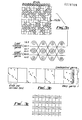
- Fig. 1 is a fragmentary cross-sectional view, taken along the machine direction, of one type of weave pattern constructed in accordance with the invention and having load-control yarns passing through the interior portion of the fabric in the machine direction;
- Fig. 2 is a fragmentary cross-sectional view similar to that of Fig. 1, showing another form of weave structure incorporating load-control yarns in accordance with the invention;
- Fig. 3 is a fragmentary cross-sectional view similar to that of Fig. 1 showing a still further form of weave structure incorporating load-control yarns in accordance with the invention;
- Figs. 3A and 3B provide weaving details for the fabric of Fig. 3; whilst Fig. 3C is a diagrammatic plan view of a part of such fabric;
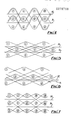
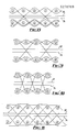
- Figs. 4 to 14 show alternative weave structures that incorporate load-control yarns in accordance with the invention.
- Referring now to the drawings, and particularly to Fig. 1, there is shown a portion of a
papermakers fabric 10 that includes a plurality ofcross-machine direction yarns 12 to 22 interwoven with a plurality of machine direction yarns 32 to 36 to provide a semi-duplex fabric. As is clearly apparent from Fig. 1, the base, or interwoven portion, of the fabric is characterised by having three ends and a six pick repeat. -
Fabric 10 includes a plurality of machine direction yarns 40 (only one of which is visible in Fig. 1) that pass directly through the centre of the fabric structure, and are arranged in parallel relationship to define an intermediate plane within the fabric, the intermediate plane lying between the plane defined by uppercross-machine direction yarns cross-machine direction yarns yarns 40 are able to undergo a higher tensile load without substantial stretch, as compared with machine direction yarns interwoven with cross-machine direction yarns. - The types of yarns that can be used to provide the interwoven fabric structure, exclusive of the load-control yarns, can be any of a variety of synthetic materials such as polyesters, polyamides, and the like. For example, nylon has excellent resistance to abrasion, although it will extend or contract in use. Thus the preferred machine direction yarns, which can be selected to provide a standard temperature and hydrolysis resistant warp structure, preferably include a combination of polyester, nylon and acrylic yarns so engineered as to combine the best properties of each yarn. For example, the polyester and nylon yarns resist wear, the nylon and acrylic yarns resist hydrolysis, the polyester and acrylic yarns resist heat, and the polyester yarns give fabric stability. Similarly, a high temperature and hydrolysis resistant warp structure can include a combination of polyester, nylon, acrylic, Nomex, and Kevlar yarns. In that case the polyester and nylon yarns resist wear, the acrylic, nylon and Nomex yarns resist hydrolysis, the polyester, acrylic and Nomex yarns resist heat, and the polyester and Kevlar yarns give fabric stability.
- In the case of the cross-machine direction yarns, standard cross-machine yarns usually combine glass, polyester, and nylon and are engineered to give excellent cross-machine stability and medium to high permeability. A design having a machine direction float face can be used to produce a smooth face fabric as shown in Fig. 14. This can be produced with standard cross-machine yarns or, for ultra smoothness, can be produced with glass and acrylic or similar cross-machine yarns.
- In the case of the load-control yarns, the preferred material is Kevlar, which has high strength, but offers poor resistance to plucking-type wear. However, by using Kevlar as the straight-through load-control yarns interiorly of the fabric, advantage can be taken of its low stretch and high strength characteristics to control overall fabric stretch. By their location in the interior of the fabric, the Kevlar yarns are fully protected from wear, and hence their relatively poor abrasion characteristics do not result in loss of fabric strength during fabric life on the paper machine. Similarly, when nylon is employed in the basic weave, because the nylon has excellent abrasion resistance, it will exhibit less wear, but the poor resistance of nylon to stretch and contraction is overcome because those properties of the fabric are controlled by the Kevlar yarns in the interior of the fabric. That Kevlar yarns are suitable for use in the context of papermakers fabrics and particularly as load-control yarns therein is totally unexpected given that Kevlar yarns are particularly susceptible to physical damage on being bent and that the machine direction yarns of a fabric are repeatedly bent or flexed on passage through the papermaking machine. Surprisingly, however, the Kevlar yarns, when employed as described above, provided excellent results. In particular, the Kevlar straight-through machine direction yarns did not exhibit the weakness inherent in such yarns, perhaps because such yarns were not crimped in the manner normal with machine direction yarns but perhaps also because they were protected by other yarns. More particularly, the performance of Kevlar was markedly better than was anticipated.
- Referring now to Fig. 2, an alternative fabric structure is illustrated in which double machine direction yarns 42, 44 and 46, 48, for example, pass over respective ones of each of the outwardly facing surfaces of each of the cross-machine direction yarns to further increase the resistance of the fabric to surface wear. This particular fabric structure is especially suitable where the fabric is subjected to a high degree of abrasion, as could exist, for example, when rusty or rough surface rolls are present in the papermaking machine. Additionally, as clearly apparent from the Fig. 2 embodiment, two load-
control yarns - Fig. 3 illustrates a flat-woven fabric comprising three layers of weft, or cross-machine direction,
yarns 56 woven with warp, or machine direction,yarns 58, there being straight load-control yarns - In a typical arrangement, the
weft yarns 56 will comprise a latex-coated multifilament glass yarn double-wrapped with 550 d'tex polyester yarn, whilst thewarp yarns 58 each comprise a three-fold yarn made up of 0.2 mm monofilament polyester (e.g. Trevira Monofilament 900C), 235 d'tex nylon (e.g. Monsanto Nylon A02) and 220 d'tex acrylic (e.g. Dralon T), the warp yarns being heat set. - The load-
control yarns - The pattern repeat is on six ends and six picks expanded for use on 12 shafts, whilst the drafting is such as to repeat on thirty-two ends, the weave and draft diagrams being as shown in Figs. 3A and 3B, like identification being used in the two parts of Fig. 3A for specific yarns.
- The warp density in the loom is typically 142 ends per 10 cms, the corresponding load-control yarn density being 47 ends per 10 cms. The reed has 472 dents per metre, and the warp and load-control yarns are drawn in at eight ends per dent using only alternate dents, there being six warp yarns and two load-control yarns in each dent so utilised.
- The weft yarns are introduced on the basis of 132 picks per 10 cms.
- The fabric of Fig. 3 will accordingly present spaced bands of yarn extending in the machine direction, with the two load-control yarns in each such band arranged within and protected by the other machine direction yarns which pass through the same dent in the reed, the band effect being illustrated diagrammatically in Fig. 3C and the positions of the load-control yarns relative to the other machine direction yarns in the same dent being apparent from Fig. 3b.
- In order to ensure maximum resistance to fabric stretch by virtue of the presence of the load-
control yarns - It has been found that the improved dimensional stability of the fabric in the machine direction thereof, and arising from the presence of the load control yarns, has a beneficial effect as regards permeability, in that the interstices between the yarns will remain substantially constant in size and will thus approximate more closely to the design geometry of the fabric. It is thought that the manner in which the cord yarns are held in the denting and drafting pattern, and are precluded from wavering or spreading contributes to the improvement.
- By way of comparison, whilst the break load of the
warp yarns 58 per se and the load-control yarns - Further base fabric weaves that can be adopted, and in which the load-control yarn concept of the present invention can be employed, are illustrated in Figs. 4 to 14. In Fig. 4, 5 and 7, 12 and 13, three-ply fabrics are illustrated, each having a pair of planes of load-
control yarns control yarns control yarns control yarns - The ends of fabrics embodying the present invention will be joined together, to form an endless belt, by means of conventional seams of a kind well known to those skilled in the art.
- In addition to providing a fabric having reduced stretch as compared with the prior known fabrics, the above-described fabric structures having load-control yarns passing therethrough can be designed to provide fabric permeability in the range of from 0 to 600 cfm, depending upon the types of yarns and the type of weave employed.
- Although, as pointed out above, a range of weave patterns can be employed to take advantage of the low stretch characteristics of load-control-yarns as hereinabove described, the preferred fabric structures for use on papermaking machines are the structures illustrated in Figs. 1, 2 and 3 of the drawings.
- Whilst it had been thought that Kevlar yarns, that is to say yarns comprising paralinked aramid filaments, had a high resistance to heat and moisture, there is clear evidence that such yarns are adversely affected by extended exposure to heat and moisture, thus leading to the widely held view that Kevlar yarns have limited application in the context of papermakers fabrics, and particularly dryer fabrics for papermaking machines. However, we have found that the strength of Kevlar yarns included in a papermakers fabric in the manner hereinproposed is not materially impaired, notwithstanding the adverse environment in which the fabric operates and the extended operating life required of that fabric.
- It is not clear why the strength characteristics are retained, although it may be that the manner in which the Kevlar yarns are surrounded by the remaining yarns present in the fabric operates to insulate the load-control yarns from the adverse effects of extended exposure to heat and moisture, this being particularly so of the Fig. 3 embodiment hereof wherein the Kevlar yarns exist within a band of machine direction yarns and form a core, as it were, to such band.
- The invention is not restricted to the exact details of the embodiments hereinbefore described, since alternatives will readily present themselves to one skilled in the art. Thus, for example, paralinked aramid yarns other than Kevlar may be used (such as, for example, TWARON) as too may yarns comprising aromatic ether amides (for example, TECNORA).
Claims (13)
Applications Claiming Priority (2)
| Application Number | Priority Date | Filing Date | Title |
|---|---|---|---|
| US1439787A | 1987-02-13 | 1987-02-13 | |
| US14397 | 1987-02-13 |
Publications (2)
| Publication Number | Publication Date |
|---|---|
| EP0278769A2 true EP0278769A2 (en) | 1988-08-17 |
| EP0278769A3 EP0278769A3 (en) | 1988-09-21 |
Family
ID=21765253
Family Applications (1)
| Application Number | Title | Priority Date | Filing Date |
|---|---|---|---|
| EP88301172A Ceased EP0278769A3 (en) | 1987-02-13 | 1988-02-12 | Papermakers fabric |
Country Status (8)
| Country | Link |
|---|---|
| EP (1) | EP0278769A3 (en) |
| JP (1) | JPS63295786A (en) |
| AU (1) | AU606385B2 (en) |
| CA (1) | CA1311400C (en) |
| FI (1) | FI880672A (en) |
| GB (1) | GB2201695B (en) |
| NZ (1) | NZ223511A (en) |
| ZA (1) | ZA88999B (en) |
Cited By (4)
| Publication number | Priority date | Publication date | Assignee | Title |
|---|---|---|---|---|
| EP0524739A1 (en) * | 1991-07-13 | 1993-01-27 | Scapa Group Plc | Improvements to papermakers and like fabrics |
| WO1997041297A1 (en) * | 1996-04-30 | 1997-11-06 | Asten, Inc. | Papermakers fabric with stacked machine and cross machine direction yarns |
| WO2005061768A1 (en) * | 2003-11-18 | 2005-07-07 | Mol Belting Company | Interwoven belt fabric |
| WO2013139890A1 (en) * | 2012-03-21 | 2013-09-26 | Voith Patent Gmbh | Papermaking fabric |
Families Citing this family (1)
| Publication number | Priority date | Publication date | Assignee | Title |
|---|---|---|---|---|
| WO1991004374A1 (en) * | 1989-09-19 | 1991-04-04 | Jwi Ltd. | Press section dewatering fabric |
Citations (2)
| Publication number | Priority date | Publication date | Assignee | Title |
|---|---|---|---|---|
| GB383097A (en) * | 1931-12-29 | 1932-11-10 | Rowland Spencer | Improvements in dryer-felts for paper machines |
| US2797713A (en) * | 1954-03-03 | 1957-07-02 | Mount Vernon Mills Inc | Drier felt |
Family Cites Families (2)
| Publication number | Priority date | Publication date | Assignee | Title |
|---|---|---|---|---|
| GB1273528A (en) * | 1968-05-14 | 1972-05-10 | Btr Industries Ltd | Improvements in or relating to fabrics and to conveyors belts composed of such fabrics |
| US3885603A (en) * | 1973-11-21 | 1975-05-27 | Creech Evans S | Papermaking fabric |
-
1988
- 1988-02-10 CA CA000558650A patent/CA1311400C/en not_active Expired - Lifetime
- 1988-02-12 JP JP63029034A patent/JPS63295786A/en active Pending
- 1988-02-12 NZ NZ223511A patent/NZ223511A/en unknown
- 1988-02-12 GB GB8803256A patent/GB2201695B/en not_active Expired - Lifetime
- 1988-02-12 FI FI880672A patent/FI880672A/en not_active IP Right Cessation
- 1988-02-12 EP EP88301172A patent/EP0278769A3/en not_active Ceased
- 1988-02-12 AU AU11688/88A patent/AU606385B2/en not_active Expired - Fee Related
- 1988-02-12 ZA ZA880999A patent/ZA88999B/en unknown
Patent Citations (2)
| Publication number | Priority date | Publication date | Assignee | Title |
|---|---|---|---|---|
| GB383097A (en) * | 1931-12-29 | 1932-11-10 | Rowland Spencer | Improvements in dryer-felts for paper machines |
| US2797713A (en) * | 1954-03-03 | 1957-07-02 | Mount Vernon Mills Inc | Drier felt |
Cited By (6)
| Publication number | Priority date | Publication date | Assignee | Title |
|---|---|---|---|---|
| US5975148A (en) * | 1990-06-06 | 1999-11-02 | Asten, Inc. | Papermakers fabric with stacked machine direction yarns forming outer floats and inner knuckles |
| US6189577B1 (en) | 1990-06-06 | 2001-02-20 | Astenjohnson, Inc. | Papermakers fabric with stacked machine direction yarns |
| EP0524739A1 (en) * | 1991-07-13 | 1993-01-27 | Scapa Group Plc | Improvements to papermakers and like fabrics |
| WO1997041297A1 (en) * | 1996-04-30 | 1997-11-06 | Asten, Inc. | Papermakers fabric with stacked machine and cross machine direction yarns |
| WO2005061768A1 (en) * | 2003-11-18 | 2005-07-07 | Mol Belting Company | Interwoven belt fabric |
| WO2013139890A1 (en) * | 2012-03-21 | 2013-09-26 | Voith Patent Gmbh | Papermaking fabric |
Also Published As
| Publication number | Publication date |
|---|---|
| GB2201695A (en) | 1988-09-07 |
| FI880672A0 (en) | 1988-02-12 |
| JPS63295786A (en) | 1988-12-02 |
| AU606385B2 (en) | 1991-02-07 |
| AU1168888A (en) | 1988-08-18 |
| GB8803256D0 (en) | 1988-03-09 |
| FI880672A (en) | 1988-08-14 |
| GB2201695B (en) | 1991-01-02 |
| ZA88999B (en) | 1988-08-10 |
| EP0278769A3 (en) | 1988-09-21 |
| NZ223511A (en) | 1990-07-26 |
| CA1311400C (en) | 1992-12-15 |
Similar Documents
| Publication | Publication Date | Title |
|---|---|---|
| US4676278A (en) | Forming fabric | |
| EP0085363B1 (en) | A papermakers' fabric | |
| EP0654559B1 (en) | Two-ply forming fabric with three or more times as many CMD yarns in the top ply than in the bottom ply | |
| US4182381A (en) | Papermakers fabrics | |
| EP0800594B1 (en) | Multilayer forming fabric | |
| US3858623A (en) | Papermakers fabrics | |
| US5368696A (en) | Papermakers wet press felt having high contact, resilient base fabric with hollow monofilaments | |
| FI85519B (en) | DOUBLE WASHER WITH FJORTON SOLVAR. | |
| US6244306B1 (en) | Papermaker's forming fabric | |
| US5657797A (en) | Press felt resistant to nip rejection | |
| EP0186406A2 (en) | Papermakers fabric having a tight bottom weft geometry | |
| US5361808A (en) | Papermaker's fabric containing finned weft yarns | |
| US4870998A (en) | Low stretch papermaking fabric | |
| EP1637634A2 (en) | Industrial two-layer fabric | |
| WO1999053135A1 (en) | Multilayer papermaking fabric | |
| EP0283181B1 (en) | Improvements in or relating to papermachine and like clothing | |
| US4789009A (en) | Sixteen harness dual layer weave | |
| US3421230A (en) | Industrial conveyor belts | |
| EP0010311B1 (en) | Paper forming fabric | |
| EP0278769A2 (en) | Papermakers fabric | |
| AU686006B2 (en) | Papermakers fabric | |
| US5167262A (en) | Join length for endless flat woven papermakers fabric | |
| US4437496A (en) | Papermakers fabrics having equalized warp sew-up | |
| GB2292755A (en) | Papermaker's fabric | |
| CA1148003A (en) | Dryer felt fabric |
Legal Events
| Date | Code | Title | Description |
|---|---|---|---|
| PUAI | Public reference made under article 153(3) epc to a published international application that has entered the european phase |
Free format text: ORIGINAL CODE: 0009012 |
|
| PUAL | Search report despatched |
Free format text: ORIGINAL CODE: 0009013 |
|
| AK | Designated contracting states |
Kind code of ref document: A2 Designated state(s): AT BE CH DE ES FR GB IT LI NL SE |
|
| AK | Designated contracting states |
Kind code of ref document: A3 Designated state(s): AT BE CH DE ES FR GB IT LI NL SE |
|
| 17P | Request for examination filed |
Effective date: 19890314 |
|
| 17Q | First examination report despatched |
Effective date: 19900814 |
|
| STAA | Information on the status of an ep patent application or granted ep patent |
Free format text: STATUS: THE APPLICATION HAS BEEN REFUSED |
|
| 18R | Application refused |
Effective date: 19911216 |