EP0272598A2 - Electrohydraulic servo system - Google Patents
Electrohydraulic servo system Download PDFInfo
- Publication number
- EP0272598A2 EP0272598A2 EP87118652A EP87118652A EP0272598A2 EP 0272598 A2 EP0272598 A2 EP 0272598A2 EP 87118652 A EP87118652 A EP 87118652A EP 87118652 A EP87118652 A EP 87118652A EP 0272598 A2 EP0272598 A2 EP 0272598A2
- Authority
- EP
- European Patent Office
- Prior art keywords
- pump
- signal
- valve
- function
- speed
- Prior art date
- Legal status (The legal status is an assumption and is not a legal conclusion. Google has not performed a legal analysis and makes no representation as to the accuracy of the status listed.)
- Granted
Links
Images

Classifications
-
- F—MECHANICAL ENGINEERING; LIGHTING; HEATING; WEAPONS; BLASTING
- F15—FLUID-PRESSURE ACTUATORS; HYDRAULICS OR PNEUMATICS IN GENERAL
- F15B—SYSTEMS ACTING BY MEANS OF FLUIDS IN GENERAL; FLUID-PRESSURE ACTUATORS, e.g. SERVOMOTORS; DETAILS OF FLUID-PRESSURE SYSTEMS, NOT OTHERWISE PROVIDED FOR
- F15B19/00—Testing; Calibrating; Fault detection or monitoring; Simulation or modelling of fluid-pressure systems or apparatus not otherwise provided for
- F15B19/002—Calibrating
-
- G—PHYSICS
- G05—CONTROLLING; REGULATING
- G05B—CONTROL OR REGULATING SYSTEMS IN GENERAL; FUNCTIONAL ELEMENTS OF SUCH SYSTEMS; MONITORING OR TESTING ARRANGEMENTS FOR SUCH SYSTEMS OR ELEMENTS
- G05B19/00—Programme-control systems
- G05B19/02—Programme-control systems electric
- G05B19/18—Numerical control [NC], i.e. automatically operating machines, in particular machine tools, e.g. in a manufacturing environment, so as to execute positioning, movement or co-ordinated operations by means of programme data in numerical form
- G05B19/414—Structure of the control system, e.g. common controller or multiprocessor systems, interface to servo, programmable interface controller
-
- G—PHYSICS
- G05—CONTROLLING; REGULATING
- G05B—CONTROL OR REGULATING SYSTEMS IN GENERAL; FUNCTIONAL ELEMENTS OF SUCH SYSTEMS; MONITORING OR TESTING ARRANGEMENTS FOR SUCH SYSTEMS OR ELEMENTS
- G05B2219/00—Program-control systems
- G05B2219/30—Nc systems
- G05B2219/33—Director till display
- G05B2219/33337—For each axis a processor, microprocessor
-
- G—PHYSICS
- G05—CONTROLLING; REGULATING
- G05B—CONTROL OR REGULATING SYSTEMS IN GENERAL; FUNCTIONAL ELEMENTS OF SUCH SYSTEMS; MONITORING OR TESTING ARRANGEMENTS FOR SUCH SYSTEMS OR ELEMENTS
- G05B2219/00—Program-control systems
- G05B2219/30—Nc systems
- G05B2219/41—Servomotor, servo controller till figures
- G05B2219/41309—Hydraulic or pneumatic drive
Definitions
- the present invention relates to electrohydraulic servo systems as described in the preamble of claim 1.
- a pump is coupled through a plurality of pressure compensated flow control servo valves to a corresponding plurality of loads, such as hydraulic actuators or motors.
- loads such as hydraulic actuators or motors.
- the moving components of an earth excavator may be coupled to electrohydraulic actuators controlled by a master controller responsive to operator lever or joystick inputs.
- the pump is controlled to deliver an output pressure equal to the highest load pressure plus an incremental load sensing pressure drop, which is a function of servo valve design.
- a network of shuttle valves f. i. EP 66,151
- the pump is mechanically controlled to deliver an output pressure equal to such highest load pressure plus the load sensing pressure drop of the servo valve coupled to that load.
- a further and more specific object of the invention is to provide an electrohydraulic servo system of the described type which includes pressure compensated flow control valves coupled to the various loads, and a pump controller responsive to flow demand at the several valves for controlling pump output to supply the sum of such demands.
- a further and yet more specific object of the invention is to provide an electrohydraulic system having a pump controller as described which automatically compensates for changes in pump input speed.
- an electrohydraulic servo control system includes a pressure compensated flow control valve for variably feeding hydraulic fluid to a load at a fluid flow rate which is a predetermined function of an electronic valve control signal.
- a variable output pump such as a variable displacement pump, is coupled to a source of motive power to feed hydraulic fluid under pressure from a source to the servo valve.
- a pump controller provides a displacement control input to the pump and includes circuitry responsive to the valve control signal for controlling pump displacement as a function of fluid flow required at the valve.
- a plurality of pressure compensated flow control valves variably feed hydraulic fluid to a corresponding plurality of loads at fluid flow rates which vary as individual predetermined functions of electrical control signals to the valves.
- An electronic servo control is coupled to each valve and includes circuitry for receiving input command signals indicative of motion desired at the correpsonding load and feedback signals indicative of actual motion at the load.
- a control signal is generated and transmitted to each valve as a function of a difference between the corresponding input and feedback signals.
- the valve control signal is indicative of fluid flow velocity at the valve required to obtain desired motion at the corresponding load.
- the pump controller receives all of the valve control signals from the several servo controllers and provides a control signal to the pump as a function of the sum of the several valve fluid flow rates needed to obtain desired motion.
- the pump control signal is provided as a combined function of flow demand and pump speed. That is, the pump displacement command is obtained as a function of the relationship b*Qc/N, where Qc is total flow demand, N is pump speed, and b is a variable which depends upon pump speed and thus accounts for volumetric inefficiencies at the pump as a factor of speed.
- Yet another feature of the invention contemplates limitation of pump displacement as a function of power available at the pump power source - e. g., the vehicle engine.
- a sensor is coupled to the engine throttle for providing a signal indicative of engine speed desired by the operator. If measured engine speed drops below such desired engine speed, the pump is off-stroked to reduce engine load and allow the engine to return to desired speed.
- the command signals to the valve controller are correspondingly scaled so that the valves are not commanded to provide more fluid than the pump can supply.
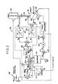
- Fig. 1 illustrates an electrohydraulic servo system 10 in accordance with an exemplary embodiment of the invention as comprising a pair of servo valves 12, 14 coupled to a variable output pump 16 for variably feeding hydraulic fluid from pump 16 to respective linear actuators 18, 20.
- Each valve 12, 14 has an associated electronic valve controller 22, 24 respectively responsive to input velocity commands V1 and V2 from an operator joystick 26 or the like through a master controller 27 for obtaining desired motion at actuators 18, 20 and the associated loads 1, 2 coupled thereto. More specifically, input velocity command V1 is first integrated in integrators 221 (the variable "S" being the conventional Laplace variable) to provide a position command signal R1.
- a sensor 28 is coupled to the piston 30 of actuator 18 and provides a feedback signal Y1 indicative of actual position of actuator piston 30 to a comparing means 222 which also receives the command signal R1 and delivers an error signal E1 indicative of a difference between desired and actual position signals R1 and Y1.
- E1 is fed through an amplifier 223 having gain K1 to obtain a valve flow command signal U1.
- Servo valve 12 is a pressure compensated flow control valve which feeds fluid to actuator 18 at a rate Q1* which is a predetermined function of flow command signal U1.
- Valve controller 24 in the embodiment of Fig. 1 is identical to controller 22 hereinabove described, with the corresponding gain and signals being designated by the suffix "2".
- Valve 12, actuator 18 and valve controller 22, as well as valve 14, actuator 20 and valve controller 24, thus each comprise a closed-loop velocity-control servo valve and actuator system responsive to velocity input commands V1, V2 from joystick 26 for varying fluid rate or flow through servo valves 12, 14, and thereby obtaining desirec motion at the loads coupled to actuators 18, 20.
- each valve/controller combination 12, 22 and 14, 24 is a single unit or assembly.
- Variable output pump 16 preferably is a variable displacement pump having an input shaft 32 coupled to a source 34 of motive power, such as the engine of an earth excavator in the example noted herinabove. Pump 16 is coupled to and controlled by a pump controller 36 which includes a programmed microprocessor 38 illustrated functionally in Fig. 2.
- the valve flow command signals U1, U2 are received at pump controller 36 from valve controllers 22, 24.
- Valve flow signals Q1, Q2 representing the flows Q1* and Q2* correspond to each flow command U1, U2 and are obtained preferably by referring to a look-up table 40, 42 in which the flow characteristics Q of respective valves 12, 14 are prestored as a function of input flow command U.
- the flow/command characteristics are illustrated as being identical at 40, 42 in Fig.
- a further look-up table 46 which relates composite flow Qc to functionally compensated or required pump displacement Dcf for differing incremental values N1 ... Nn of pump speed N.
- the variable b is the slope of each curve N1 ... Nn in Fig. 2. For values of N between incremented values N1 ... Nn, suitable interpolation is employed.
- the resulting signal Dcf thus indicates total pump displacement required to yield a fluid rate Qc* at measured pump speed N. (Dcf can be greater than Dmax).
- a speed limit command NL is received from the vehicle throttle 48 through a potentiometer 49 or other suitable transducer and indicates power available at engine 34.
- Speed limit NL is compared in comparator 51 with actual pump speed N.
- the resulting difference NL-N is dealt with in an examination circuit 50 to establish a displacement command Dcn based upon pump speed. If the difference is negative, the pump 16 is to be allowed to assume the maximum displacement, and if the difference is positive, it may be necessary for the pump to assume minimum displacement.
- the two displacement command signals Dcn and Dcf are examined in minimum comparator 52, and the lesser of the two is selected as pump displacement command signal Dc.
- Pump displacement command Dc is compared in comparator 53 with actual pump displacement D indicated at the sensor 54 responsive to pump yoke position.
- the difference or error Ed is multiplied by a constant K, subject to compensation for bias or offset, and then controls duty cycle of pulsewidth modulation amplifier 56.
- the output of amplifier 56 is fed to the displacement control solenoid 58 of pump 16.
- the arrangement 53, 54, 56, 58 forms a pump control servo loop 60 which, in its operation, seeks to make Ed to zero.
- the output Dcn of circuit 50 is limited at a rate limit circuit 55 selectable by the operator to prevent cycling of engine speed about the speed limit NL.
- Commands Dcn and Dcf are also fed to a circuit 61 where the ration Dcn/Dcf is obtained. As long as this ratio is equal to or greater than one, meaning that pump speed N is above the limit NL, the output Kd of circuit 61 is equal to one. However, if the ratio Dcn/Dcf is less than one, the value is fed as the parameter Kd to master controller 27 (Fig.1). Input commands from operator joystick 26 are multiplied by the parameter Kd, so that velocity commands V1, V2 to servo controller 22, 24 are effectively scaled to a lower level which the engine and pump can supply. Thus, pump 16 is off-stroked, and load motion commands V1, V2 are correspondingly reduced, when engine speed drops. This permits the engine to maintain service to other systems coupled thereto, such as vehicle steering or braking, which have higher priority.
- pump controller 36 receives electrical input signals indicative of flow command signals U1, U2 at the servo valves, and derives therefrom corresponding valve flow signals Q1, Q2 based upon the predetermined and unique functional relationship of valve flow to flow command in pressure compensated flow control servo valves. Individual servo valve flows are summed to obtain a composite flow signal Qc. Required pump displacement Dcf is then obtained as a function of total flow signal Qc and pump speed signal N. As long as required displacement so indicated is below the overload level of the pump-drive engine, pump displacement Dcf based upon total required fluid flow is employed as the displacement command Dc at the input to the pump control servo loop 60.
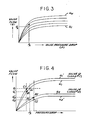
- Fig. 3 illustrates a family of curves relating valve flow Q to pressure drop P across a pressure compensated flow control servo valve for various valve flow control inputs U1-Un (and corresponding valve pilot pressure).
- U1-Un and corresponding valve pilot pressure
- Fig. 4 illustrates a family of curves relating valve flow Q to pressure drop P across a pressure compensated flow control servo valve for various valve flow control inputs U1-Un (and corresponding valve pilot pressure).
- a microprocessor-based pump controller 36 has been disclosed, and is currently preferred. However, both the pump and valve controllers could be constructed of discrete digital or analog circuitry without departing from the invention in its broadest aspects. Look-up tables have been described in connection with circuits 40-46 in Fig. 2, and are currently preferred for reasons of speed and versatility. However, the look-up table functions could be preformed by mathematical operations in analog or digital circuitry.
Abstract
Description
- The present invention relates to electrohydraulic servo systems as described in the preamble of claim 1.
- In conventional electrohydraulic servo control systems, a pump is coupled through a plurality of pressure compensated flow control servo valves to a corresponding plurality of loads, such as hydraulic actuators or motors. In a typical application, the moving components of an earth excavator may be coupled to electrohydraulic actuators controlled by a master controller responsive to operator lever or joystick inputs. The pump is controlled to deliver an output pressure equal to the highest load pressure plus an incremental load sensing pressure drop, which is a function of servo valve design. Typically, a network of shuttle valves (f. i. EP 66,151) is coupled to the various loads and delivers an output to the pump control input indicative of highest load pressure. The pump is mechanically controlled to deliver an output pressure equal to such highest load pressure plus the load sensing pressure drop of the servo valve coupled to that load.
- It has been proposed to eliminate the shuttle valve network, and to provide pump control by electronically sensing actual pressure at the various loads (see EP 247,335). Such a system requires pressure sensors at both of the servo valve ports at each load, a pressure sensor at the pump outlet, and a corresponding multiplicity of conductors for feeding the pressure sensor signals to an electronic pump controller. Although enhanced control characteristics can be obtained reduction in cost and complexity remains desirable.
- It is therefore a general object of the present invention to provide an electrohydraulic servo system of the described character which exhibits reduced cost and complexity as compared with prior art systems of similar type. A further and more specific object of the invention is to provide an electrohydraulic servo system of the described type which includes pressure compensated flow control valves coupled to the various loads, and a pump controller responsive to flow demand at the several valves for controlling pump output to supply the sum of such demands. A further and yet more specific object of the invention is to provide an electrohydraulic system having a pump controller as described which automatically compensates for changes in pump input speed.
- In accordance with the present invention, an electrohydraulic servo control system includes a pressure compensated flow control valve for variably feeding hydraulic fluid to a load at a fluid flow rate which is a predetermined function of an electronic valve control signal. A variable output pump, such as a variable displacement pump, is coupled to a source of motive power to feed hydraulic fluid under pressure from a source to the servo valve. A pump controller provides a displacement control input to the pump and includes circuitry responsive to the valve control signal for controlling pump displacement as a function of fluid flow required at the valve.
- In a preferred embodiment of the invention, a plurality of pressure compensated flow control valves variably feed hydraulic fluid to a corresponding plurality of loads at fluid flow rates which vary as individual predetermined functions of electrical control signals to the valves. An electronic servo control is coupled to each valve and includes circuitry for receiving input command signals indicative of motion desired at the correpsonding load and feedback signals indicative of actual motion at the load. A control signal is generated and transmitted to each valve as a function of a difference between the corresponding input and feedback signals. The valve control signal is indicative of fluid flow velocity at the valve required to obtain desired motion at the corresponding load. The pump controller receives all of the valve control signals from the several servo controllers and provides a control signal to the pump as a function of the sum of the several valve fluid flow rates needed to obtain desired motion.
- In accordance with another feature of the invention, the pump control signal is provided as a combined function of flow demand and pump speed. That is, the pump displacement command is obtained as a function of the relationship b*Qc/N, where Qc is total flow demand, N is pump speed, and b is a variable which depends upon pump speed and thus accounts for volumetric inefficiencies at the pump as a factor of speed.
- Yet another feature of the invention contemplates limitation of pump displacement as a function of power available at the pump power source - e. g., the vehicle engine. A sensor is coupled to the engine throttle for providing a signal indicative of engine speed desired by the operator. If measured engine speed drops below such desired engine speed, the pump is off-stroked to reduce engine load and allow the engine to return to desired speed. The command signals to the valve controller are correspondingly scaled so that the valves are not commanded to provide more fluid than the pump can supply.
- The invention, together with additional objects, features and advantages thereof, will be best understood from the following description, the appended claims and the accompanying drawings in which
- Fig. 1 is a functional block diagram of an electrohydraulic servo system in accordance with a presently preferred embodiment of the invention;
- Fig. 2 is a detailed functional block diagram of the pump controller illustrated in Fig. 1, and
- Figs. 3 and 4 are graphic illustrations which are useful in describing operation of the embodiment of Figs. 1 and 2.
- Fig. 1 illustrates an
electrohydraulic servo system 10 in accordance with an exemplary embodiment of the invention as comprising a pair ofservo valves variable output pump 16 for variably feeding hydraulic fluid frompump 16 to respectivelinear actuators 18, 20. Eachvalve electronic valve controller 22, 24 respectively responsive to input velocity commands V1 and V2 from anoperator joystick 26 or the like through amaster controller 27 for obtaining desired motion atactuators 18, 20 and theassociated loads 1, 2 coupled thereto. More specifically, input velocity command V1 is first integrated in integrators 221 (the variable "S" being the conventional Laplace variable) to provide a position command signal R1. Asensor 28 is coupled to thepiston 30 ofactuator 18 and provides a feedback signal Y1 indicative of actual position ofactuator piston 30 to acomparing means 222 which also receives the command signal R1 and delivers an error signal E1 indicative of a difference between desired and actual position signals R1 and Y1. E1 is fed through anamplifier 223 having gain K1 to obtain a valve flow command signal U1.Servo valve 12 is a pressure compensated flow control valve which feeds fluid toactuator 18 at a rate Q1* which is a predetermined function of flow command signal U1.Valve controller 24 in the embodiment of Fig. 1 is identical to controller 22 hereinabove described, with the corresponding gain and signals being designated by the suffix "2". -
Valve 12,actuator 18 and valve controller 22, as well asvalve 14, actuator 20 andvalve controller 24, thus each comprise a closed-loop velocity-control servo valve and actuator system responsive to velocity input commands V1, V2 fromjoystick 26 for varying fluid rate or flow throughservo valves actuators 18, 20. Most preferably, each valve/controller combination -
Variable output pump 16 preferably is a variable displacement pump having aninput shaft 32 coupled to asource 34 of motive power, such as the engine of an earth excavator in the example noted herinabove.Pump 16 is coupled to and controlled by apump controller 36 which includes a programmedmicroprocessor 38 illustrated functionally in Fig. 2. The valve flow command signals U1, U2 are received atpump controller 36 fromvalve controllers 22, 24. Valve flow signals Q1, Q2 representing the flows Q1* and Q2* correspond to each flow command U1, U2 and are obtained preferably by referring to a look-up table 40, 42 in which the flow characteristics Q ofrespective valves servo valve - Signals Q1, Q2, indicative of individual valve fluid flows are summed at 43 to obtain a composite fluid flow signal Qc. Roughly displacement required at
pump 16 to supply fluid at rate Qc* is equal to Qc divided by pump speed N. However, this relationship does not account for losses or volumetric efficiencies atpump 16 as a function of pump speed. Accordingly, functionally compensated pump displacement Dcf required to supply fluid at rate Qc* at pump speed N is to be made larger, determined according to the relationship Dcf=bQc/N, where be is a parameter which varies with pump speed N, and N is received from apump speed sensor 44. In accordance with the preferred embodiment of the invention illustrated in Fig. 2, the foregoing relationship is implemented in a further look-up table 46 which relates composite flow Qc to functionally compensated or required pump displacement Dcf for differing incremental values N1 ... Nn of pump speed N. The variable b is the slope of each curve N1 ... Nn in Fig. 2. For values of N between incremented values N1 ... Nn, suitable interpolation is employed. The resulting signal Dcf thus indicates total pump displacement required to yield a fluid rate Qc* at measured pump speed N. (Dcf can be greater than Dmax). - To prevent
pump 16 from being stroked to a level which will overloadengine 34, a speed limit command NL is received from thevehicle throttle 48 through a potentiometer 49 or other suitable transducer and indicates power available atengine 34. Speed limit NL is compared incomparator 51 with actual pump speed N. The resulting difference NL-N is dealt with in an examination circuit 50 to establish a displacement command Dcn based upon pump speed. If the difference is negative, thepump 16 is to be allowed to assume the maximum displacement, and if the difference is positive, it may be necessary for the pump to assume minimum displacement. The two displacement command signals Dcn and Dcf are examined in minimum comparator 52, and the lesser of the two is selected as pump displacement command signal Dc. Pump displacement command Dc is compared incomparator 53 with actual pump displacement D indicated at thesensor 54 responsive to pump yoke position. The difference or error Ed is multiplied by a constant K, subject to compensation for bias or offset, and then controls duty cycle ofpulsewidth modulation amplifier 56. The output ofamplifier 56 is fed to thedisplacement control solenoid 58 ofpump 16. Thearrangement control servo loop 60 which, in its operation, seeks to make Ed to zero. - Most preferably, the output Dcn of circuit 50 is limited at a rate limit circuit 55 selectable by the operator to prevent cycling of engine speed about the speed limit NL.
- Commands Dcn and Dcf are also fed to a
circuit 61 where the ration Dcn/Dcf is obtained. As long as this ratio is equal to or greater than one, meaning that pump speed N is above the limit NL, the output Kd ofcircuit 61 is equal to one. However, if the ratio Dcn/Dcf is less than one, the value is fed as the parameter Kd to master controller 27 (Fig.1). Input commands fromoperator joystick 26 are multiplied by the parameter Kd, so that velocity commands V1, V2 toservo controller 22, 24 are effectively scaled to a lower level which the engine and pump can supply. Thus, pump 16 is off-stroked, and load motion commands V1, V2 are correspondingly reduced, when engine speed drops. This permits the engine to maintain service to other systems coupled thereto, such as vehicle steering or braking, which have higher priority. - Thus, in operation, pump
controller 36 receives electrical input signals indicative of flow command signals U1, U2 at the servo valves, and derives therefrom corresponding valve flow signals Q1, Q2 based upon the predetermined and unique functional relationship of valve flow to flow command in pressure compensated flow control servo valves. Individual servo valve flows are summed to obtain a composite flow signal Qc. Required pump displacement Dcf is then obtained as a function of total flow signal Qc and pump speed signal N. As long as required displacement so indicated is below the overload level of the pump-drive engine, pump displacement Dcf based upon total required fluid flow is employed as the displacement command Dc at the input to the pumpcontrol servo loop 60. - Fig. 3 illustrates a family of curves relating valve flow Q to pressure drop P across a pressure compensated flow control servo valve for various valve flow control inputs U1-Un (and corresponding valve pilot pressure). In accordance with prior art hereinabove discussed, it was attempted to maintain pressure across the valve associated with the greatest load at the load sensing pressure Pa, and thereby obtain corresponding flow Qa through that valve. In accordance with the present invention, however, an entirely different approach is taken. That is, the pump is controlled to deliver flow Qa based upon known valve command input U (and corresponding pilot pressure), and valve pressure drop Pa becomes the dependent variable. The result, in terms of automatically stabilizing valve flow under varying load conditions, is illustrated in Fig. 4. Initially, it is assumed that the two pressure controlled
servo valves valve 12 encounters increased resistance, the pressure drop acrossvalve 12 automatically decreases from point A1 to point B1, with corresponding decrease in flow from Q1 to Q1ʹ. Meanwhile, since pump output remains constant, pressure atvalve 14 increases from point A2 to point B2, and valve flow correspondingly increases from Q2 to Q2ʹ. However, such change in fluid flow automatically results in a change in velocity at each load, decreasing at Load-1 and increasing at Load-2. Such changes in velocity result in changing error signals E1, E2 within therespective valve controllers 22, 24, automatically increasing the flow command atvalve 12 from U1 to U1ʹ while decreasing the flow command atvalve 14 from U2 to U2ʹ. Operation at the respective valves thus automatically shifts to the points C1 and C2 in Fig. 4 at which valve flows return to the initial levels of Q1 and Q2 respectively, while pressure drop across the respective valves vary from the initial Pa level because of change in load conditions. - Although the invention has been disclosed in connection with a specific presently preferred embodiment thereof, many alternatives and modifications may be implemented without departing from the principles of the invention. For example, position and acceleration servo loops, or combinations of position, velocity and acceleration, may be employed in
servo controllers 22, 24. The invention is by no means limited to a pair of loads or to linear actuators as illustrated in Fig. 1. Indeed, benefits of implementation of the invention increase as the number of loads increases. Nor are the principles of the invention limited specifically to variable displacement-type pumps, although these are preferred. - A microprocessor-based
pump controller 36 has been disclosed, and is currently preferred. However, both the pump and valve controllers could be constructed of discrete digital or analog circuitry without departing from the invention in its broadest aspects. Look-up tables have been described in connection with circuits 40-46 in Fig. 2, and are currently preferred for reasons of speed and versatility. However, the look-up table functions could be preformed by mathematical operations in analog or digital circuitry.
Claims (11)
and pump control means (36) for controlling output of said pump (16), characterized in that
said pump control means (36) comprises:
means for receiving said valve control signal (U1, U2),
means (40, 42) for providing a signal (Q1, Q2, Qc) indicative of fluid rate at said valve (12, 14) as said predetermined function of said valve control signal (U), and
means (46, 52) for providing an output control signal (Dc, Dcf) to said pump (16) as a function of said flow-indicative signal (Qc).
wherein said means for providing said flow-indicative signal (Q1, Q2, Qc) comprises first look-up table means (40, 42) relating flow rate (Q) to valve command signal (U) at said predetermined function associated with said valve (12, 14).
further comprising means (44) for sensing speed of motive input power to said pump (16) and providing a corresponding speed signal (N), and wherein said pump control means (36) comprises means (52) for providing said output control signal (Dcf, Dc) to said plump (16) as a combined function of said flow-indicative signal (Qc) and said speed signal (N).
wherein said plump control means (36) comprises means (46) for providing said output control signal (Dcf) as a function of the relationship bQc/N, where Qc is said flow-indicative signal, N is said speed signal, and b is a constant selected as a function of speed N.
wherein said output control signal providing means (46, 52) comprises second look-up table means (46) relating said output control signal (Dcf) to said flow-indicative signal (Qc) as differing predetermined functions of said speed signal (N).
wherein said source of motive power comprises an engine (34), and
wherein said pump control means (36) further comprises means (49) responsive to throttle commands to said engine for limiting said output control signal (Dc) to said pump (16) to a level (DcN) below overload on said engine (34).
wherein said throttle command-responsive means (49) comprises means responsive to the engine throttle (48) for providing a signal (NL) indicative of desired engine speed set by said throttle (48), means (44) for sensing speed of motive input power to said pump (16) and providing a corresponding pump speed signal (N), means (51) for comparing said desired-speed signal (NL) with said pump-speed signal (N), and means (50, 52) for limiting said output control signals (Dc) where said pump-speed signal (N) is less than said desired-speed signal (NL).
an electronic servo control (22, 24) coupled to said one at least provided valve (12, 14) and including means for receiving a first signal (V1, V2) indicative of motion desired at the corresponding load (1, 2), means (222) for receiving a second signal (Y1, Y2) indicative of actual motion at said corresponding load (1, 2), and means (222, 223) for generating a valve control signal (U1, U2) to said valve (12, 14) as a function of a difference between said first and second signals, each said valve control signal (U1, U2) being indicative of fluid flow at the corresponding said valve required to obtain said desired motion at the associated load.
wherein said means (40, 42, 43, 46) for providing said flow control signal (Dc) to said pump (16) comprises means (46) for providing a first pump control signal (Dcf) as a function of said rate-indicative signals (Q1, Q2); and
wherein said output-limiting means (50, 52) comprises means (50) for providing a second pump control signal (DcN) as a function of a difference between said desired-speed signal (NL) and pump speed signal (N), and means (52) for controlling said pump (16) as a function of the lesser of said first and second pump control signals (DcN, Dcf).
further comprising means (61) for scaling each of said first signals (V1, V2) as a function of a ratio (DcN/Dcf) between said first and second pump control signals.
wherein said output-limiting means (50, 52) further comprises means (55) for selectively clamping rate of change of said second pump control signal (DcN).
Applications Claiming Priority (2)
| Application Number | Priority Date | Filing Date | Title |
|---|---|---|---|
| US06/944,657 US4741159A (en) | 1986-04-08 | 1986-12-22 | Power transmission |
| US944657 | 1986-12-22 |
Publications (3)
| Publication Number | Publication Date |
|---|---|
| EP0272598A2 true EP0272598A2 (en) | 1988-06-29 |
| EP0272598A3 EP0272598A3 (en) | 1990-05-16 |
| EP0272598B1 EP0272598B1 (en) | 1993-09-01 |
Family
ID=25481821
Family Applications (1)
| Application Number | Title | Priority Date | Filing Date |
|---|---|---|---|
| EP87118652A Expired - Lifetime EP0272598B1 (en) | 1986-12-22 | 1987-12-16 | Electrohydraulic servo system |
Country Status (5)
| Country | Link |
|---|---|
| US (1) | US4741159A (en) |
| EP (1) | EP0272598B1 (en) |
| JP (1) | JPS63186001A (en) |
| CA (1) | CA1311175C (en) |
| DE (1) | DE3787266T2 (en) |
Cited By (3)
| Publication number | Priority date | Publication date | Assignee | Title |
|---|---|---|---|---|
| FR2689576A1 (en) * | 1992-04-03 | 1993-10-08 | Barmag Barmer Maschf | Hydraulic system with differential pressure regulation. |
| GB2251232B (en) * | 1990-09-29 | 1995-01-04 | Samsung Heavy Ind | Automatic actuating system for actuators of excavator |
| EP1563146B1 (en) * | 2002-10-08 | 2019-03-20 | Volvo Construction Equipment AB | A method for controlling a vehicle and a computer program for performing the method |
Families Citing this family (14)
| Publication number | Priority date | Publication date | Assignee | Title |
|---|---|---|---|---|
| DE3928230A1 (en) * | 1989-08-26 | 1991-02-28 | Wilfried Boldt | Hydraulic hub brake with integrated pump and constriction - provides adjustments of fluid flow and resistance in housing connected by spokes to rim of wheel |
| DE3928229A1 (en) * | 1989-08-26 | 1991-02-28 | Wilfried Boldt | Hydraulic hub brake with integrated pump and construction - provides adjustments of fluid flow and resistance in housing connected by spokes to rim of wheel |
| KR950008533B1 (en) * | 1991-11-30 | 1995-07-31 | 삼성중공업주식회사 | Control devices output of hydraulic pump |
| US5267441A (en) * | 1992-01-13 | 1993-12-07 | Caterpillar Inc. | Method and apparatus for limiting the power output of a hydraulic system |
| DE4327313C2 (en) * | 1993-08-13 | 2001-07-05 | Mannesmann Rexroth Ag | Process for regulating the pressure of a hydrostatic machine with an adjustable delivery volume |
| US5525043A (en) * | 1993-12-23 | 1996-06-11 | Caterpillar Inc. | Hydraulic power control system |
| US5468126A (en) * | 1993-12-23 | 1995-11-21 | Caterpillar Inc. | Hydraulic power control system |
| US5576962A (en) * | 1995-03-16 | 1996-11-19 | Caterpillar Inc. | Control system and method for a hydrostatic drive system |
| US6349543B1 (en) * | 1998-06-30 | 2002-02-26 | Robert Moshe Lisniansky | Regenerative adaptive fluid motor control |
| JP4114684B2 (en) * | 2005-08-11 | 2008-07-09 | コベルコ建機株式会社 | Control device for hydraulic cylinder and work machine equipped with the same |
| DE102007058211A1 (en) | 2007-12-04 | 2009-06-10 | Siemens Ag | Method for operating a fluidic line system |
| US9429152B2 (en) * | 2010-10-28 | 2016-08-30 | Bosch Rexroth Corporation | Method for controlling variable displacement pump |
| DE102015215466A1 (en) * | 2015-08-13 | 2017-02-16 | Ksb Aktiengesellschaft | Adjustment of the flow rate of a consumer |
| KR102023954B1 (en) * | 2018-02-07 | 2019-09-23 | 엘에스산전 주식회사 | Monitoring and load controlling system of distribution panel |
Citations (5)
| Publication number | Priority date | Publication date | Assignee | Title |
|---|---|---|---|---|
| US3985467A (en) * | 1975-05-27 | 1976-10-12 | Milton Roy Company | Constant pressure pump |
| GB2102511A (en) * | 1981-07-29 | 1983-02-02 | Nissan Motor | Improved hydraulic control system for industrial vehicle |
| EP0111208A1 (en) * | 1982-11-26 | 1984-06-20 | Vickers Incorporated | Power transmission |
| GB2157460A (en) * | 1984-04-13 | 1985-10-23 | Voith Gmbh J M | Adjustment mechanism for the displacement volume of a displacement machine |
| EP0228707A1 (en) * | 1985-12-28 | 1987-07-15 | Hitachi Construction Machinery Co., Ltd. | Control system of hydraulic construction machinery |
Family Cites Families (9)
| Publication number | Priority date | Publication date | Assignee | Title |
|---|---|---|---|---|
| DE2050882A1 (en) * | 1970-10-16 | 1972-04-20 | Bosch Gmbh Robert | Hydraulic rotary motor drive |
| US4029439A (en) * | 1975-12-22 | 1977-06-14 | Abex Corporation | Control system for variable displacement pumps |
| DE2902264A1 (en) * | 1979-01-22 | 1980-07-24 | Bosch Gmbh Robert | CONTROL DEVICE FOR A HYDRAULIC SYSTEM |
| JPS56139316A (en) * | 1980-01-07 | 1981-10-30 | Komatsu Ltd | Power loss reduction controller for oil-pressure type construction machine |
| JPH0228721B2 (en) * | 1980-10-30 | 1990-06-26 | Nissei Plastics Ind Co | SHASHUTSUYUATSUSOCHINIOKERUKAFUKABOSHISOCHI |
| JPS5837302A (en) * | 1981-08-31 | 1983-03-04 | Mitsubishi Heavy Ind Ltd | Pump control device of working machine |
| JPS60201102A (en) * | 1984-03-27 | 1985-10-11 | Sekitan Rotenbori Kikai Gijutsu Kenkyu Kumiai | Hydraulic operating device |
| JPS60208605A (en) * | 1984-03-31 | 1985-10-21 | Ishikawajima Harima Heavy Ind Co Ltd | On-deck machinery control equipment for ship |
| JPS6392801A (en) * | 1986-10-07 | 1988-04-23 | Komatsu Ltd | Control method of hydraulic system |
-
1986
- 1986-12-22 US US06/944,657 patent/US4741159A/en not_active Expired - Lifetime
-
1987
- 1987-12-16 EP EP87118652A patent/EP0272598B1/en not_active Expired - Lifetime
- 1987-12-16 DE DE87118652T patent/DE3787266T2/en not_active Expired - Lifetime
- 1987-12-17 CA CA000554714A patent/CA1311175C/en not_active Expired - Fee Related
- 1987-12-21 JP JP62323628A patent/JPS63186001A/en active Pending
Patent Citations (5)
| Publication number | Priority date | Publication date | Assignee | Title |
|---|---|---|---|---|
| US3985467A (en) * | 1975-05-27 | 1976-10-12 | Milton Roy Company | Constant pressure pump |
| GB2102511A (en) * | 1981-07-29 | 1983-02-02 | Nissan Motor | Improved hydraulic control system for industrial vehicle |
| EP0111208A1 (en) * | 1982-11-26 | 1984-06-20 | Vickers Incorporated | Power transmission |
| GB2157460A (en) * | 1984-04-13 | 1985-10-23 | Voith Gmbh J M | Adjustment mechanism for the displacement volume of a displacement machine |
| EP0228707A1 (en) * | 1985-12-28 | 1987-07-15 | Hitachi Construction Machinery Co., Ltd. | Control system of hydraulic construction machinery |
Cited By (4)
| Publication number | Priority date | Publication date | Assignee | Title |
|---|---|---|---|---|
| GB2251232B (en) * | 1990-09-29 | 1995-01-04 | Samsung Heavy Ind | Automatic actuating system for actuators of excavator |
| FR2689576A1 (en) * | 1992-04-03 | 1993-10-08 | Barmag Barmer Maschf | Hydraulic system with differential pressure regulation. |
| GB2265995B (en) * | 1992-04-03 | 1996-01-31 | Barmag Barmer Maschf | Hydraulic system |
| EP1563146B1 (en) * | 2002-10-08 | 2019-03-20 | Volvo Construction Equipment AB | A method for controlling a vehicle and a computer program for performing the method |
Also Published As
| Publication number | Publication date |
|---|---|
| DE3787266D1 (en) | 1993-10-07 |
| US4741159A (en) | 1988-05-03 |
| EP0272598A3 (en) | 1990-05-16 |
| CA1311175C (en) | 1992-12-08 |
| DE3787266T2 (en) | 1994-03-24 |
| EP0272598B1 (en) | 1993-09-01 |
| JPS63186001A (en) | 1988-08-01 |
Similar Documents
| Publication | Publication Date | Title |
|---|---|---|
| EP0272598B1 (en) | Electrohydraulic servo system | |
| EP0193947B1 (en) | Power transmission | |
| US4759183A (en) | Control arrangement for at least two hydraulic loads fed by at least one pump | |
| US4856278A (en) | Control arrangement for at least two hydraulic consumers fed by at least one pump | |
| US5214916A (en) | Control system for a hydraulic work vehicle | |
| EP0332132B1 (en) | Electrohydraulic servo system, especially for injection molding machines | |
| US6385970B1 (en) | Underspeed control system for a hydromechanical drive system and method of operating same | |
| EP0041273B1 (en) | Circuit pressure control system for hydrostatic power transmission | |
| EP1798346B1 (en) | Control device for hydraulic drive machine | |
| US5527156A (en) | Apparatus for and method of controlling engine and pumps of hydraulic construction equipment | |
| EP0286649B1 (en) | Proportional valve control apparatus for fluid systems | |
| EP0071909B1 (en) | Vehicular power steering system | |
| US5951258A (en) | Torque limiting control system for a hydraulic work machine | |
| US5249421A (en) | Hydraulic control apparatus with mode selection | |
| EP0393697B1 (en) | Electrohydraulic system | |
| US4106367A (en) | Pressure control apparatus for the automatic transmission of automotive vehicles | |
| EP0087773A1 (en) | Variable displacement pump control system and a valve for such system | |
| CA1242513A (en) | Power transmission | |
| US6173572B1 (en) | Method and apparatus for controlling a bypass valve of a fluid circuit | |
| US5540049A (en) | Control system and method for a hydraulic actuator with velocity and force modulation control | |
| EP3770419A1 (en) | Hydraulic compressed medium supply assembly, method and mobile working machine | |
| JPH09509243A (en) | Hydraulic flow priority system | |
| GB1560242A (en) | Apparatus for controlling the speed of an hydraulic motor | |
| US4884475A (en) | Automotive drive system for machines and vehicles | |
| EP0372899A1 (en) | Apparatus and method for the simultaneous control of two or more related variables |
Legal Events
| Date | Code | Title | Description |
|---|---|---|---|
| PUAI | Public reference made under article 153(3) epc to a published international application that has entered the european phase |
Free format text: ORIGINAL CODE: 0009012 |
|
| AK | Designated contracting states |
Kind code of ref document: A2 Designated state(s): DE FR GB IT SE |
|
| PUAL | Search report despatched |
Free format text: ORIGINAL CODE: 0009013 |
|
| AK | Designated contracting states |
Kind code of ref document: A3 Designated state(s): DE FR GB IT SE |
|
| 17P | Request for examination filed |
Effective date: 19901116 |
|
| 17Q | First examination report despatched |
Effective date: 19920218 |
|
| ITTA | It: last paid annual fee | ||
| ITF | It: translation for a ep patent filed |
Owner name: DE DOMINICIS & MAYER S.R.L. |
|
| GRAA | (expected) grant |
Free format text: ORIGINAL CODE: 0009210 |
|
| AK | Designated contracting states |
Kind code of ref document: B1 Designated state(s): DE FR GB IT SE |
|
| REF | Corresponds to: |
Ref document number: 3787266 Country of ref document: DE Date of ref document: 19931007 |
|
| ET | Fr: translation filed | ||
| PGFP | Annual fee paid to national office [announced via postgrant information from national office to epo] |
Ref country code: SE Payment date: 19931117 Year of fee payment: 7 |
|
| PLBE | No opposition filed within time limit |
Free format text: ORIGINAL CODE: 0009261 |
|
| STAA | Information on the status of an ep patent application or granted ep patent |
Free format text: STATUS: NO OPPOSITION FILED WITHIN TIME LIMIT |
|
| 26N | No opposition filed | ||
| PG25 | Lapsed in a contracting state [announced via postgrant information from national office to epo] |
Ref country code: SE Effective date: 19941217 |
|
| EAL | Se: european patent in force in sweden |
Ref document number: 87118652.4 |
|
| EUG | Se: european patent has lapsed |
Ref document number: 87118652.4 |
|
| REG | Reference to a national code |
Ref country code: GB Ref legal event code: IF02 |
|
| PGFP | Annual fee paid to national office [announced via postgrant information from national office to epo] |
Ref country code: GB Payment date: 20061106 Year of fee payment: 20 |
|
| PGFP | Annual fee paid to national office [announced via postgrant information from national office to epo] |
Ref country code: FR Payment date: 20061201 Year of fee payment: 20 |
|
| PGFP | Annual fee paid to national office [announced via postgrant information from national office to epo] |
Ref country code: DE Payment date: 20061229 Year of fee payment: 20 |
|
| PGFP | Annual fee paid to national office [announced via postgrant information from national office to epo] |
Ref country code: IT Payment date: 20061231 Year of fee payment: 20 |
|
| REG | Reference to a national code |
Ref country code: GB Ref legal event code: PE20 |
|
| PG25 | Lapsed in a contracting state [announced via postgrant information from national office to epo] |
Ref country code: GB Free format text: LAPSE BECAUSE OF EXPIRATION OF PROTECTION Effective date: 20071215 |