EP0271969A2 - DC power-superposed multiplex transmission system with single parallel cable - Google Patents
DC power-superposed multiplex transmission system with single parallel cable Download PDFInfo
- Publication number
- EP0271969A2 EP0271969A2 EP87304780A EP87304780A EP0271969A2 EP 0271969 A2 EP0271969 A2 EP 0271969A2 EP 87304780 A EP87304780 A EP 87304780A EP 87304780 A EP87304780 A EP 87304780A EP 0271969 A2 EP0271969 A2 EP 0271969A2
- Authority
- EP
- European Patent Office
- Prior art keywords
- power
- frequency
- cable
- audio
- regulator
- Prior art date
- Legal status (The legal status is an assumption and is not a legal conclusion. Google has not performed a legal analysis and makes no representation as to the accuracy of the status listed.)
- Granted
Links
Images


Classifications
-
- H—ELECTRICITY
- H04—ELECTRIC COMMUNICATION TECHNIQUE
- H04N—PICTORIAL COMMUNICATION, e.g. TELEVISION
- H04N7/00—Television systems
- H04N7/18—Closed-circuit television [CCTV] systems, i.e. systems in which the video signal is not broadcast
- H04N7/183—Closed-circuit television [CCTV] systems, i.e. systems in which the video signal is not broadcast for receiving images from a single remote source
-
- H—ELECTRICITY
- H04—ELECTRIC COMMUNICATION TECHNIQUE
- H04N—PICTORIAL COMMUNICATION, e.g. TELEVISION
- H04N23/00—Cameras or camera modules comprising electronic image sensors; Control thereof
- H04N23/60—Control of cameras or camera modules
- H04N23/66—Remote control of cameras or camera parts, e.g. by remote control devices
Definitions
- the present invention relates to a DC power-superposed transmission system e.g. for audio video signals using an interphone cable made of a pair of parallel PVC-coated wires.
- Interphone whose power consumption is relatively small usually uses dry cells as the driving power source.
- the door phone camera in the outdoor unit cannot be driven by the dry cell provided for supplying power to the interphone, because the camera requires larger power.
- an object of the present invention is to provide a DC power-superposed multiplex transmission system using a telephone communication cable, which is capable to transmit simultaneous two-way or one-way video signals and simultaneous two-way audio and/or control (audio/control) signals along with one-way DC power transmission.
- Another object of the present invention is to provide a power transmission system in which DC power is multiplexed by a series regulator of constant current type in sending end with such audio signals in low-frequency band and with such carriers of video signal in high-frequency band, transmitted along with those through a telephone communication cable and demultiplexed from those at the receiving end of the outdoor unit by the regulator similar to the sending end.
- output impedance of the series regulator of a constant current type at sending end (hereinafter, this regulator will be referred to simply as “sending regulator”) and that of the similar regulator at receiving end (hereinafter, this regulator will be referred to simply as “receiving regula tor”) are necessary to be high enough, compared with the cable's characteristic impedance within such a wide range as to 10 MHz.
- Another objects of the present invention is to provide DC power-superposed multiplex transmission system in which DC power is multiplexed by choke coils of small type with such carriers of audio/control signals, that is, such audio/control carriers in medium-frequency band and with such carriers of video signals, that is, such video carriers in high-frequency band, transmitted along with those through a telephone communication cable and separated from those at the receiving terminal of the outdoor unit.
- Another object of the present invention is to provide a power transmission system which remotely controls the DC voltage at the power-receiving terminal of the outdoor unit using a multiplexed control signal to keep the DC voltage specified regardless of the cable length.
- a power transmission system in which DC power is superposed on audio signals and video carriers, transmitted through the telephone communication cable, is constructed, comprising said sending regulator, said receiving regulator and a conversion regulator which operates as a buffer to the following regulator of constant voltage type to drive CCD camera, frequency-modulator of video signals and its processors.
- the telephone communication cable is not only limited to an inhouse cable (for example, a interphone cable composed of a pair of parallel or twisted solid wires each having a diameter of 0.5 mm and coated with poly-vivyl chloride, i.e., PVC), but also for interphone it includes a pair of parallel vinyl lines generally used to AC power supply (composed of a pair of stranded wires (20/0.18 or 30/0.18)).
- any of the above-mentioned communication cables will be referred to simply as cable.
- the DC power-superposed multiplex transmission system is constructed, comprising frequency-modulators means mounted in both the power sending and receiving ends to modulate each specified carrier with each audio/control and video signal, and power choke coils instead of said series regulators mounted at both the power sending and receiving terminals, which have such inductance as to turn into high impedance at said specified carrier frequency, compared with the cable's characteristic impedance to prevent the carriers except DC component from short-circuiting.
- a balanced cable transmission system using said audio/control and video carriers is compactly constructed in which it is able to easily transmit DC power by means of the bridge circuit with choke coils of small type.
- a line transformer is needed at each cable-termination for inputting and/or outputting audio/control and video carriers.
- the power transmission system is constructed, comprising a frequency-modulator of a control carrier with the DC voltage drop at the receiving terminal mounted in the power-receiving end in order to feed back the control carrier to the power-sending end through the cable, and a frequency-demodulator of the control carrier into the "DC drop" control signal means provided in the power sending end in order to regulate the supply voltage by a regulator to keep constant the DC voltage at the power receiving terminal regardless of difference of the cable length.
- a power transmission system of the first embodiment of the present invention is described below with reference to Figs. 1 through 4.
- Fig. 1 is a block diagram of a power transmission system of the first embodiment of the present invention.
- Fig. 2 shows a typical circuit making up the constant current regulator of Fig. 1.
- 10 is a indoor unit and 20 is a outdoor unit of the TV door phone system.
- 40 is the said cable for connection between the indoor unit 10 and the outdoor unit 20.
- the indoor unit 10 comprises an audio signal processing block, a video signal processing block and a power supply block.
- the audio signal processing block comprises a indoor handset 11, an audio signal's peak-limiter 12, a DC-blocking capacitor 13 and a lowpass filter (LPF) 14.
- the video signal processing block comprises a highpass filter (HPF) 15, a frequency-demodulator 16 (including a limiter) and a TV monitor 17.
- the power supply block comprises a DC power supply 18 and a first constant current regulator (said sending regulator) 19.
- the outdoor unit 20 comprises an audio signal processing block, a video signal processing block and a power receiving block.
- the audio signal processing block comprises a mike/speaker outdoor assembly 21, an audio signal's peak-limiter 22, a DC-blocking capacitor 23 and a lowpass filter (LPF) 24.
- the video signal processing block comprises a TV camera 25, a frequency-modulator 26 and a highpass filter (HPF) 27.
- the power receiving block comprises a second constant current regulator (said receiving regulator) 28, a current-voltage conversion regulator (said conversion regulator) 29 and a constant voltage regulator 30. This regulator 30 drives the TV camera 25, the frequency-modulator 20 and the other processors and need not always be included in the construction.
- a typical cable widely used of said cable 40 composes of a pair of PVC-coated parallel solidwires of 0.5 mm in each diameter and its transmission characteristics of 100 m in span show an attenuation of 6 dB at 10 MHz.
- said sending regulator 19 comprises PNP transistors TR1 and TR1 of Darlington connector, and said receiving regulator 28 comprises NPN transistors TR1 ⁇ and TR2 ⁇ of Darlington connection.
- the sending and receiving regulators 19 and 28 constitute complementary regulators.
- the constant current outputs I1 and I2 of the regulators 19 and 28 are set at the same value through fine adjustment of the variable resistors r1 and r1 ⁇ included in the regulators 19 and 28, respectively.
- Resistors r2 and r2 ⁇ supply base current to the initial stage transistors TR1 and TR1 ⁇ of Darlington connection in the regulators 19 and 28, respectively.
- the resistors r2 and r2 ⁇ are desirably set such impedance higher than the cable characteristic impedance within from the audio base-band to the frequency-modulated video carrier band or numerically 200 ohms at least so as not to cause more than 3 dB of attenuation of the transmitted audio signal and video carrier.
- the said conversion regulator 29 connected with the said receiving regulator 28 comprises a zener diode "ZD". Part of the current output I2 from the receiving regulator 28 is allowed to overflow into the Zener diode "ZD" to stabilize the operation of the following regulator of constant current type 30.
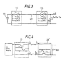
- Fig. 3 is an equivalent circuit diagram of the constant current regulators shown in Fig. 2.
- the said sending regulators 19 comprises a constant current source I1 and internal impedance R1 and C1.
- the internal impedances R1, R2, C1 and C2 of the constant current regulators 19 and 28 may not shunt the cable impedance, those impedance are desirably set fairly larger than the characteristic impedance of the said cable 40.
- the characteristic impedance of a pair of PVC-coated parallel solid-wires of 0.5 mm in each diameter is measured as about 180 ohms. Therefore, the equivalent resistors R1 and R2 larger than 1000 ohms are easily achieved by selecting an appropriate power transistors suitable for the constant current regulators 19 and 28.
- the capacitors C1 and C2 result mainly from the collector-base capacitance C cb of the power transistor for the series regulator, and shunt the termination resistance (about 180 ohms) within the video carrier band. If the collector-base capacitance C cb becomes large, therefore, reflection at the higher frequency component of the video carrier increases, resulting in deteriorated transmission characteristics. Considering this fact, transistors for the series regulators should have a small collector-base capacitance C cb which depends on the collector-base voltage. It is desirable, therefore, to select a optimal collector-emitter voltage with due regard to power dissipation for the system
- the constant current output I1 from the sending regulator 19 is transmitted, superposed on the audio signal sent from the indoor unit 10, through the cable 40 to the outdoor unit 20.
- the receiving regulator 28 receives the constant current output I1
- the receiving regulator 28 outputs constant current I2 of the same magnitude as the constant current I1.
- the constant current I2 is supplied to the conversion regulator 29 and to the constant voltage regulator 30 which outputs constant voltage for actuating the TV camera 25, etc.
- the audio signal is baseband-transmitted in both ways between the indoor unit 10 and the outdoor unit 20 by the respective audio signal processing blocks.
- the DC blocking capacitors 13 and 23 eliminate DC component from the audio signal, and the lowpass filters 14 and 24 restrict the audio signal band within 10 kHz or lower.
- a carrier is modulated with the video signal outputted from the TV camera 25 by the frequency-modulator 26 which disperses the carrier spectrum within from 1.5 MHz to 10 MHz.
- the video carrier After passing through the highpass filter 27, the video carrier is superposed on the audio signal and transmitted from the outdoor unit 20 to the indoor unit 10.
- the audio signal and the video carrier are separated by these spectrum band, there is no cross-talk.
- the audio signal whose spectrum band's upper limit is not higher than about 10 kHz is transmitted without virtually no attenuation through the cable 40.
- the Multiplex signals composed of an audio signal and a video carrier are separated into the audio signal and the video carrier by the lowpass filter 14 and the highpass filter 15 in the indoor unit 10.
- the video carrier is then demodulated by the frequency-demodulator 16 into the video signal which is supplied to the TV monitor 17.
- the audio signal's peak limiters 12 and 22 are provided in the indoor unit 10 and the outdoor unit 20, respectively, as shown in Fig. 1.
- the constant current regulators 19 and 28 may be connected to either terminal of the cable 40.
- the constant current regulator at the power receiving terminal in the outdoor unit 20
- the constant current regulator at the power receiving terminal in the outdoor unit 20
- the constant current regulator at the power receiving terminal in the outdoor unit 20
- transistors of the similar type PNP type
- the DC resistance of the cable increases in proportion to the cable length. According to the present invention, if the cable resistance is 10 ohms and the cable DC current 0.5 A, for instance, the cable DC drop of 5 V can be compensated by raising up by 5 V the DC supply voltage of the power sending terminal. Thus, it is possible to supply DC power from the indoor unit to the outdoor unit of several 100 m away.
- the invention is applied to a door phone camera system. Not to mention, the present invention is also applicable to a TV telephone system.
- Fig. 5 shows a block diagram of a TV door phone system in which the multiplex transmission of audio/control and video carriers superposed on the DC power with the cable.
- 100 is a indoor unit
- 102 is a outdoor unit installed at the entrance
- 104 is the said cable for connection between the indoor unit 100 and the outdoor unit 102.
- the indoor unit 100 contains a mike 106 and mike-amplifier 107 for communication with visitors facing to the outdoor unit 102, an audio frequency-modulator 108 for frequency-modulation of a carrier of about 380 kHz with an audio/control signal outputted from the mike-amplifier 107, a bandpass filter 10 (for instance, with a passband of (380 ⁇ 20) kHz) to restrict the spectrum band of the audio/control carrier outputted from the audio/control frequency-modulator 108, and a line transformer 112 which not only transmits the carrier from the bandpass filter 110 via the cable to the outdoor unit 102 but also receives carriers transmitted via the cable from the outdoor unit 102.
- a mike 106 and mike-amplifier 107 for communication with visitors facing to the outdoor unit 102
- an audio frequency-modulator 108 for frequency-modulation of a carrier of about 380 kHz with an audio/control signal outputted from the mike
- the indoor unit 100 To receive multiplex carriers composed of a carrier frequency-modulated with a video signal, that is, a video carrier and a carrier frequency-modulated with an audio/control signal, that is, an audio/control carrier transmitted from the outdoor unit 102, the indoor unit 100 further contains a video frequency-demodulator 118, a TV monitor 120 supplied by a video signal outputted from the video frequency-demodulator 118, a audio frequency-demodulator 122, a speaker 124 and a speaker-driving amplifier 123 supplied by the audio/control signal outputted from frequency-demodulator 122.
- the video frequency-demodulator 18 and the audio/control frequency-demodulator 122 demodulate the carriers into the video and the audio/control signals, respectively.
- 115 is a DC blocking capacitor and 113 a pad for impedance matching between the line transformer 112 and the cable 104.
- the indoor unit 100 further contains a DC power supply 126, a constant voltage regulator 128 and a pair of power choke coils 130/131 which is the characteristic feature of the second embodiment.
- Each power choke coil turns into a high impedance for the audio/control carriers superposed on DC component at the power sending terminal "A".
- the outdoor unit 102 contains a mike 132 and a mike-amplifier 133 for communication with receivers facing to the indoor unit 100, a audio/control frequency-modulator 134 for frequency-modulation of the audio/control carrier of about 420 kHz with the audio signal outputted from the mike-amplifier 133, a TV camera 136 to pick up visitors, a video frequency-modulator 138 for frequency-modulation of a video carrier with the video signal outputted from the TV camera 136, a highpass filter 140 with cut-off frequency of about 1.5 MHz following the video frequency-modulator 138, a bandpass filter 139 with passband of, for instance, about (420 ⁇ 20) kHz following the audio/control frequency-modulator 134 and a line transformer 142 which not only outputs the carriers to the cable but also inputs carriers from the cable.
- a mike 132 and a mike-amplifier 133 for communication with receivers facing to
- a synchronizing-pulse's tip i.e., sync-tip
- a white-peak of the signal to 4.4 MHz of that as used in the video tape recorder of VHS format.
- a sync-tip is allocated to 7 MHz and a white-peak to 10 MHz as used in the "highband mode" video tape recorders for the broadcasting station use.
- the outdoor unit 102 To receive multiplex carriers sent from the indoor unit 100, the outdoor unit 102 also contains a bandpass filter 144 whose passband is (380 ⁇ 20) KHz for instance, an audio/control frequency-demodulator 148 for frequency-demodulation of the carrier from the bandpass filter 144, a speaker-driving amplifier 149 and a speaker 150.
- 152 is a DC blocking capacitor and 143 a pad for impedamce matching between the line transformer 142 and the cable 104.
- the outdoor unit 102 also contains a power supply block comprising a pair of power choke coils 154/155 and a constant voltage regulator 156.
- Fig. 6 shows a typical characteristic curve of the cable 104 composed of, for instance, parallel solid wires of 100 m in length and of 0.5 mm in each diameter.
- a in Fig. 6 is indicated the allocated band of the audio/control carrier transmitted from the indoor unit 100 to the outdoor unit 102, by “b” the allocated band of the audio/control carrier transmitted from the outdoor unit 102 to the indoor unit 100, by “c” the allocated band of the video carrier of the monochrome (BW) video signal and by “d” the allocated band of the video carrier of such composite signal as NTSC, PAL or SECAM signal.
- the power choke coils more than 100 ⁇ H (of the inherent self-resonance frequency higher than 10 MHz) turn into a high impedance for the modulated carriers of 300kHz at least or higher frequency, compared with the cable characteristic impedance, so that it is possible to superpose DC power on the audio/control and the video carriers at the power sending terminal and to separate DC power from the multiplex carriers at the power receiving terminal.
- the volume of 0.5 A DC-superposed choke coils which turns into 200 ohms at a frequency of (300 - 20) kHz is nearly equal to 1/10000 of that at a frequency of 30 Hz which is assumed to be cut-off frequency to separate DC component from the audio/control baseband signal. Consequently, DC-superposed multiplex carriers transmission system can be compactly constructed. According to the present invention, it is not necessary to install a special cable for DC power and/or video signal transmission in addition to a cable for the audio/control signal. Moreover, the DC power transmission system of the second embodiment of the present invention doesn't involve constant current regulators of complicated circuit-construction that have been needed in the prior art. As a result, the problem of substantial power loss generated at the constant current regulators is eliminated.
- a line transformer is needed at each cable-termination.
- a transformer has a passband in which lower cut-off frequency is determined by the inductance of the primary coil and higher cut-off frequency by the self-resonance frequency inherent in the primary/secondary coils.
- the broken line is indicated a typical characteristic curve of a balanced cable transmission using line transformers at both cable termination and with the chain line, that of the 3 dB pads insertion transmission.
- the voltage in the power receiving terminal may vary with the cable length because DC resistance of the cable changes with the cable length. Such inconstantness is not preferable for operation of the outdoor unit.
- Fig. 7 shows the construction of a power transmission system of third embodiment of the present invention and the same parts as shown in Fig. 6 are allocated with the same reference numbers as in Fig. 6 and their explanation is omitted.
- a voltage-control regulator 128 ⁇ is used in place of the constant voltage regulator 128.
- the indoor unit 100 contains detector means 129 for detecting DC voltage fluctuation at the receiving terminal, transmitted through the lower band of the audio/control signal outputted from the frequency-demodulator 122.
- the detector means 129 comprises a lowpass filter 129a with cutoff frequency lower than 100Hz, a frequency-voltage (F-V) converter 129 (frequency-demodulator for control signal) for converting of the control carrier which the lowpass filter 129a has separated from audio signal, to the "DC drop” control signal corresponding to the DC voltage drop along the cable, a differential amplifier 129d which compares the "DC drop” with a reference (supposing 0 V) 129c, and an FET transistor 129e which amplifies the output of the detector means.
- F-V converter 129 frequency-demodulator for control signal
- the outdoor unit 102 includes a power receiving block comprising a pair of power choke coils 154/155, a constant voltage regulator 156, a voltage control oscillator 158 as frequency-modulator of a control carrier with the DC voltage drop in the cable 104, and a lowpass filter 159 with cutoff frequency lower than 100Hz.
- the DC drop voltage at the power receiving terminal is in proportion to the cable length and with that voltage the voltage control oscillator (VCO) 158 frequency-modulates a control carrier of 50 Hz and outputs the carrier through the lowpass filter 159 with cutoff frequency lower than 100 Hz to the audio/control frequency-modulator 134 which frequency-modulates an audio/control carrier with the multiplexed signal of the audio signal and the control carrier.
- VCO voltage control oscillator
- the outdoor unit 100 sends the audio/control carrier to the power sending terminal on the assumption that the audio signal from the outdoor unit has a passband of about (0.3 to 3) kHz and that the control carrier has, for instance, a passband of about (50 ⁇ 10) Hz.
- the audio/control carrier is demodulated by the frequency-demodulator 122 into the audio/control signals from which the control carrier is separated by the lowpass filter 129a.
- the control carrier is demodulated by F/V converter 129b into the "DC drop" control signal which drives the regulator 128 ⁇ to regulate for compensating the DC voltage drop at the power receiving terminal. Accordingly, DC voltage at the power receiving terminal is always kept almost constant regardless of the cable length or resistance.
- the audio/control carriers as well as the video carrier are bidirectionally transmitted by frequency-division multiplex to avoid cross-talk. Consequently, the hybrid transformers or bidirectional amplifiers required for audio signal baseband-transmission in case of the power transmission system of the first embodiment shown in Fig. 1 are not needed in the second and third embodiments.
- the second and third embodiments makes difficult the howling generating which is caused by acoustic loop circuits formed by hybrid transformers, bidirectional amplifiers and/or acoustic transmission from a speaker to a mike in the indoor or outdoor unit. This permits speaker's volume to be raised up and its articulation to be improved more than the interphone system by baseband-transmission using hybrid transformers or bidirectional amplifiers.
- the MF waves interference induced along the cable can be minimized by setting the audio/control carrier bands lower than the broadcast bands of (0.5 to 1.5) MHz by using line transformers 112/142.
Abstract
Description
- The present invention relates to a DC power-superposed transmission system e.g. for audio video signals using an interphone cable made of a pair of parallel PVC-coated wires.
- Interphone whose power consumption is relatively small usually uses dry cells as the driving power source. When a TV door phone system is used in place of the existing interphone, however, the door phone camera in the outdoor unit cannot be driven by the dry cell provided for supplying power to the interphone, because the camera requires larger power. Moreover, when replacing the interphone with the TV door phone, it is necessary to newly install another power cable for driving the door phone camera and a co-axial cable for video signal transmission, resulting in extra installation cost. For the purpose of saving power-supply cables there is already known a method that with a co-axial cable for video signal transmission DC power may be transmitted, superposed on video signals by means of series regulators for duplexing of DC power with a video signal at the sending terminal and for de-duplexing at the receiving terminal. In general, spectra of both audio and video signals include such low-frequency components as 100 Hz at least, so that power choke coils are necessary for DC power duplexing but these are too heavy, bulky and power-dissipative to compcatly fabricate the indoor or outdoor unit.
- In view of the above, an object of the present invention is to provide a DC power-superposed multiplex transmission system using a telephone communication cable, which is capable to transmit simultaneous two-way or one-way video signals and simultaneous two-way audio and/or control (audio/control) signals along with one-way DC power transmission. By facilitating to divert from the already installed cable for interphone to that for a TV door phone system, this system can save the extra cost of new cable installation.
- Another object of the present invention is to provide a power transmission system in which DC power is multiplexed by a series regulator of constant current type in sending end with such audio signals in low-frequency band and with such carriers of video signal in high-frequency band, transmitted along with those through a telephone communication cable and demultiplexed from those at the receiving end of the outdoor unit by the regulator similar to the sending end.
- Here, output impedance of the series regulator of a constant current type at sending end (hereinafter, this regulator will be referred to simply as "sending regulator") and that of the similar regulator at receiving end (hereinafter, this regulator will be referred to simply as "receiving regula tor") are necessary to be high enough, compared with the cable's characteristic impedance within such a wide range as to 10 MHz.
- Another objects of the present invention is to provide DC power-superposed multiplex transmission system in which DC power is multiplexed by choke coils of small type with such carriers of audio/control signals, that is, such audio/control carriers in medium-frequency band and with such carriers of video signals, that is, such video carriers in high-frequency band, transmitted along with those through a telephone communication cable and separated from those at the receiving terminal of the outdoor unit.
- Another object of the present invention is to provide a power transmission system which remotely controls the DC voltage at the power-receiving terminal of the outdoor unit using a multiplexed control signal to keep the DC voltage specified regardless of the cable length.
- Other objects and further scope of applicability of the present invention will become apparent from the detailed description given hereinafter. It should be understood, however, that the detailed description and specific examples, while indicating preferred embodiments of the invention, are given by way of illustration only, since various changes and modifications within the spirit and scope of the invention will become apparent to those skilled in the art from this detailed description.
- To achieve the above objects, according to a first embodi ment of the present invention, a power transmission system in which DC power is superposed on audio signals and video carriers, transmitted through the telephone communication cable, is constructed, comprising said sending regulator, said receiving regulator and a conversion regulator which operates as a buffer to the following regulator of constant voltage type to drive CCD camera, frequency-modulator of video signals and its processors.
- Here, the telephone communication cable is not only limited to an inhouse cable (for example, a interphone cable composed of a pair of parallel or twisted solid wires each having a diameter of 0.5 mm and coated with poly-vivyl chloride, i.e., PVC), but also for interphone it includes a pair of parallel vinyl lines generally used to AC power supply (composed of a pair of stranded wires (20/0.18 or 30/0.18)). Hereinafter any of the above-mentioned communication cables will be referred to simply as cable.
- To achieve the above objects, according to a second embodiment of the present invention, the DC power-superposed multiplex transmission system is constructed, comprising frequency-modulators means mounted in both the power sending and receiving ends to modulate each specified carrier with each audio/control and video signal, and power choke coils instead of said series regulators mounted at both the power sending and receiving terminals, which have such inductance as to turn into high impedance at said specified carrier frequency, compared with the cable's characteristic impedance to prevent the carriers except DC component from short-circuiting.
- A balanced cable transmission system using said audio/control and video carriers is compactly constructed in which it is able to easily transmit DC power by means of the bridge circuit with choke coils of small type. In order to construct the balanced cable transmission system a line transformer is needed at each cable-termination for inputting and/or outputting audio/control and video carriers.
- To achieve the above objects, according to a third embodiment of the present invention, the power transmission system is constructed, comprising a frequency-modulator of a control carrier with the DC voltage drop at the receiving terminal mounted in the power-receiving end in order to feed back the control carrier to the power-sending end through the cable, and a frequency-demodulator of the control carrier into the "DC drop" control signal means provided in the power sending end in order to regulate the supply voltage by a regulator to keep constant the DC voltage at the power receiving terminal regardless of difference of the cable length.
- There is another method of compensation of DC voltage drop, in which the sending regulator of constant current type keeps equal to the DC current enough to be feeded to the outdoor unit. In the balanced cable transmission using the above-mentioned bridge circuit with choke coils, the output impedance of the series regulator is not necessary to keep high within a whole spectrum range of carrier transmission. Therefore, by the series regulator of a constant current type the DC voltage at receiving terminal of the outdoor unit can be easily kept to a specified value, detecting the DC current returned back into the indoor unit.
- The present invention will become fully understood from the detailed description given hereinbelow and the accompanying drawings which are given by way of illustration only, and thus are not limitative of the present invention and wherein:
- Fig. 1 is a block diagram schematically showing the construction of the first embodiment of the invention:
- Fig. 2 is a specific circuit diagram of the constant current regulator in Fig. 1:
- Fig. 3 is an equivalent circuit of the constant current regulator:
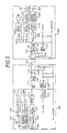
- Fig. 4 is a block diagram schematically showing another construction of the first embodiment of the present invention:
- Fig. 5 is a block diagram showing the construction of the second embodiment of the present invention:
- Fig. 6 shows the transmission characteristic curves of the communication cable used in the embodiment of Fig. 5; and
- Fig. 7 is a block diagram showing the construction of the third embodiment of the present invention.
- A power transmission system of the first embodiment of the present invention is described below with reference to Figs. 1 through 4.
- Fig. 1 is a block diagram of a power transmission system of the first embodiment of the present invention. Fig. 2 shows a typical circuit making up the constant current regulator of Fig. 1. Referring to Figs. 1 and 2, 10 is a indoor unit and 20 is a outdoor unit of the TV door phone system. 40 is the said cable for connection between the
indoor unit 10 and theoutdoor unit 20. - The
indoor unit 10 comprises an audio signal processing block, a video signal processing block and a power supply block. The audio signal processing block comprises aindoor handset 11, an audio signal's peak-limiter 12, a DC-blocking capacitor 13 and a lowpass filter (LPF) 14. The video signal processing block comprises a highpass filter (HPF) 15, a frequency-demodulator 16 (including a limiter) and aTV monitor 17. The power supply block comprises aDC power supply 18 and a first constant current regulator (said sending regulator) 19. - The
outdoor unit 20 comprises an audio signal processing block, a video signal processing block and a power receiving block. The audio signal processing block comprises a mike/speaker outdoor assembly 21, an audio signal's peak-limiter 22, a DC-blocking capacitor 23 and a lowpass filter (LPF) 24. The video signal processing block comprises aTV camera 25, a frequency-modulator 26 and a highpass filter (HPF) 27. The power receiving block comprises a second constant current regulator (said receiving regulator) 28, a current-voltage conversion regulator (said conversion regulator) 29 and aconstant voltage regulator 30. Thisregulator 30 drives theTV camera 25, the frequency-modulator 20 and the other processors and need not always be included in the construction. A typical cable widely used of saidcable 40 composes of a pair of PVC-coated parallel solidwires of 0.5 mm in each diameter and its transmission characteristics of 100 m in span show an attenuation of 6 dB at 10 MHz. - As shown in detail in Fig. 2, for example, said sending
regulator 19 comprises PNP transistors TR₁ and TR₁ of Darlington connector, and said receivingregulator 28 comprises NPN transistors TR₁ʹ and TR₂ʹ of Darlington connection. The sending and receivingregulators regulators regulators regulators - The said
conversion regulator 29 connected with the said receivingregulator 28 comprises a zener diode "ZD". Part of the current output I₂ from thereceiving regulator 28 is allowed to overflow into the Zener diode "ZD" to stabilize the operation of the following regulator of constantcurrent type 30. - Fig. 3 is an equivalent circuit diagram of the constant current regulators shown in Fig. 2. The said
sending regulators 19 comprises a constant current source I₁ and internal impedance R₁ and C₁. Thereceiving regulator 28 comprises R₂ and C₂. Assuming the current supplied to the followingconstant voltage regulator 30 is Ia, the current overflowing into the Zener diode ZD, Ib, is expressed as Ib = I₂ - Ia. - In order that the internal impedances R₁, R₂, C₁ and C₂ of the constant
current regulators cable 40. The characteristic impedance of a pair of PVC-coated parallel solid-wires of 0.5 mm in each diameter is measured as about 180 ohms. Therefore, the equivalent resistors R₁ and R₂ larger than 1000 ohms are easily achieved by selecting an appropriate power transistors suitable for the constantcurrent regulators - Operation of the above embodiments of the present invention is described in the following.
- The constant current output I₁ from the sending
regulator 19 is transmitted, superposed on the audio signal sent from theindoor unit 10, through thecable 40 to theoutdoor unit 20. Receiving the constant current output I₁, the receivingregulator 28 outputs constant current I₂ of the same magnitude as the constant current I₁. The constant current I₂ is supplied to theconversion regulator 29 and to theconstant voltage regulator 30 which outputs constant voltage for actuating theTV camera 25, etc. - The audio signal is baseband-transmitted in both ways between the
indoor unit 10 and theoutdoor unit 20 by the respective audio signal processing blocks. At this time, theDC blocking capacitors 13 and 23 eliminate DC component from the audio signal, and the lowpass filters 14 and 24 restrict the audio signal band within 10 kHz or lower. - Meanwhile, a carrier is modulated with the video signal outputted from the
TV camera 25 by the frequency-modulator 26 which disperses the carrier spectrum within from 1.5 MHz to 10 MHz. After passing through thehighpass filter 27, the video carrier is superposed on the audio signal and transmitted from theoutdoor unit 20 to theindoor unit 10. - Since the audio signal and the video carrier are separated by these spectrum band, there is no cross-talk. The audio signal whose spectrum band's upper limit is not higher than about 10 kHz is transmitted without virtually no attenuation through the
cable 40. - The Multiplex signals composed of an audio signal and a video carrier are separated into the audio signal and the video carrier by the
lowpass filter 14 and thehighpass filter 15 in theindoor unit 10. The video carrier is then demodulated by the frequency-demodulator 16 into the video signal which is supplied to theTV monitor 17. - Inputting an audio signal with a large swing results in short-circuiting of the collector-emitter voltage of the transistor for the constant
current regulator peak limiters 12 and 22 are provided in theindoor unit 10 and theoutdoor unit 20, respectively, as shown in Fig. 1. - In the above first embodiment, the constant
current regulators cable 40. Alternatively, as shown in Fig. 4, the constant current regulator at the power receiving terminal (in the outdoor unit 20) may be connected to the earth return side of the cable. With this alternative construction, transistors of the similar type (PNP type) may be used for the sendingregulator 19 and for the receivingregulator 28. The DC resistance of the cable increases in proportion to the cable length. According to the present invention, if the cable resistance is 10 ohms and the cable DC current 0.5 A, for instance, the cable DC drop of 5 V can be compensated by raising up by 5 V the DC supply voltage of the power sending terminal. Thus, it is possible to supply DC power from the indoor unit to the outdoor unit of several 100 m away. In the above embodiment, the invention is applied to a door phone camera system. Not to mention, the present invention is also applicable to a TV telephone system. - The second embodiment of the invention which eliminates the above possible disadvantages of the first embodiment is described now with reference to Figs. 5 and 6.
- Fig. 5 shows a block diagram of a TV door phone system in which the multiplex transmission of audio/control and video carriers superposed on the DC power with the cable. Referring to Fig. 5, 100 is a indoor unit, and 102 is a outdoor unit installed at the entrance. 104 is the said cable for connection between the
indoor unit 100 and theoutdoor unit 102. - To transmit audio/control and video carriers superposed on DC power to the
outdoor unit 102, theindoor unit 100 contains amike 106 and mike-amplifier 107 for communication with visitors facing to theoutdoor unit 102, an audio frequency-modulator 108 for frequency-modulation of a carrier of about 380 kHz with an audio/control signal outputted from the mike-amplifier 107, a bandpass filter 10 (for instance, with a passband of (380 ± 20) kHz) to restrict the spectrum band of the audio/control carrier outputted from the audio/control frequency-modulator 108, and aline transformer 112 which not only transmits the carrier from thebandpass filter 110 via the cable to theoutdoor unit 102 but also receives carriers transmitted via the cable from theoutdoor unit 102. - To receive multiplex carriers composed of a carrier frequency-modulated with a video signal, that is, a video carrier and a carrier frequency-modulated with an audio/control signal, that is, an audio/control carrier transmitted from the
outdoor unit 102, theindoor unit 100 further contains a video frequency-demodulator 118, aTV monitor 120 supplied by a video signal outputted from the video frequency-demodulator 118, a audio frequency-demodulator 122, aspeaker 124 and a speaker-drivingamplifier 123 supplied by the audio/control signal outputted from frequency-demodulator 122. After the multiplex carriers are separated by a highpass filter 117 (for instance, with cut-off frequency of about 1.5MHz) and a bandpass filter 119 (for instance, with passband of (420 ± 20) KHz) into the video and the audio/control carriers, respectively, the video frequency-demodulator 18 and the audio/control frequency-demodulator 122 demodulate the carriers into the video and the audio/control signals, respectively. 115 is a DC blocking capacitor and 113 a pad for impedance matching between theline transformer 112 and thecable 104. - For a power supply block, the
indoor unit 100 further contains aDC power supply 126, aconstant voltage regulator 128 and a pair of power choke coils 130/131 which is the characteristic feature of the second embodiment. Each power choke coil turns into a high impedance for the audio/control carriers superposed on DC component at the power sending terminal "A". - To transmit the audio/control and the video carriers to the
indoor unit 100, theoutdoor unit 102 contains amike 132 and a mike-amplifier 133 for communication with receivers facing to theindoor unit 100, a audio/control frequency-modulator 134 for frequency-modulation of the audio/control carrier of about 420 kHz with the audio signal outputted from the mike-amplifier 133, aTV camera 136 to pick up visitors, a video frequency-modulator 138 for frequency-modulation of a video carrier with the video signal outputted from theTV camera 136, ahighpass filter 140 with cut-off frequency of about 1.5 MHz following the video frequency-modulator 138, abandpass filter 139 with passband of, for instance, about (420 ± 20) kHz following the audio/control frequency-modulator 134 and aline transformer 142 which not only outputs the carriers to the cable but also inputs carriers from the cable. - In case of the frequency-modulation of a video carrier with a monochrome TV signal, for example, a synchronizing-pulse's tip (i.e., sync-tip) is allocated to 3.4 MHz of video carrier and a white-peak of the signal to 4.4 MHz of that as used in the video tape recorder of VHS format. And in case of such composite signal as NTSC, PAL or SECAM signal a sync-tip is allocated to 7 MHz and a white-peak to 10 MHz as used in the "highband mode" video tape recorders for the broadcasting station use.
- To receive multiplex carriers sent from the
indoor unit 100, theoutdoor unit 102 also contains abandpass filter 144 whose passband is (380± 20) KHz for instance, an audio/control frequency-demodulator 148 for frequency-demodulation of the carrier from thebandpass filter 144, a speaker-drivingamplifier 149 and aspeaker 150. 152 is a DC blocking capacitor and 143 a pad for impedamce matching between theline transformer 142 and thecable 104. - The
outdoor unit 102 also contains a power supply block comprising a pair of power choke coils 154/155 and aconstant voltage regulator 156. - Fig. 6 shows a typical characteristic curve of the
cable 104 composed of, for instance, parallel solid wires of 100 m in length and of 0.5 mm in each diameter. By "a" in Fig. 6 is indicated the allocated band of the audio/control carrier transmitted from theindoor unit 100 to theoutdoor unit 102, by "b" the allocated band of the audio/control carrier transmitted from theoutdoor unit 102 to theindoor unit 100, by "c" the allocated band of the video carrier of the monochrome (BW) video signal and by "d" the allocated band of the video carrier of such composite signal as NTSC, PAL or SECAM signal. - As clear from the above description, according to the second embodiment of the present invention, the power choke coils more than 100 µH (of the inherent self-resonance frequency higher than 10 MHz) turn into a high impedance for the modulated carriers of 300kHz at least or higher frequency, compared with the cable characteristic impedance, so that it is possible to superpose DC power on the audio/control and the video carriers at the power sending terminal and to separate DC power from the multiplex carriers at the power receiving terminal. For example, supposing that an audio/control carrier of 300 kHz is modulated with an audio/control signal into a carrier band of (300 ± 20) kHz, the volume of 0.5 A DC-superposed choke coils which turns into 200 ohms at a frequency of (300 - 20) kHz, is nearly equal to 1/10000 of that at a frequency of 30 Hz which is assumed to be cut-off frequency to separate DC component from the audio/control baseband signal. Consequently, DC-superposed multiplex carriers transmission system can be compactly constructed. According to the present invention, it is not necessary to install a special cable for DC power and/or video signal transmission in addition to a cable for the audio/control signal. Moreover, the DC power transmission system of the second embodiment of the present invention doesn't involve constant current regulators of complicated circuit-construction that have been needed in the prior art. As a result, the problem of substantial power loss generated at the constant current regulators is eliminated.
- In order to construct the balanced cable transmission system a line transformer is needed at each cable-termination. In practice, a transformer has a passband in which lower cut-off frequency is determined by the inductance of the primary coil and higher cut-off frequency by the self-resonance frequency inherent in the primary/secondary coils. With the broken line is indicated a typical characteristic curve of a balanced cable transmission using line transformers at both cable termination and with the chain line, that of the 3 dB pads insertion transmission.
- In the first embodiment of the invention, the voltage in the power receiving terminal may vary with the cable length because DC resistance of the cable changes with the cable length. Such inconstantness is not preferable for operation of the outdoor unit.
- Fig. 7 shows the construction of a power transmission system of third embodiment of the present invention and the same parts as shown in Fig. 6 are allocated with the same reference numbers as in Fig. 6 and their explanation is omitted. In the third embodiment of the invention, a voltage-control regulator 128ʹ is used in place of the
constant voltage regulator 128. In addition, theindoor unit 100 contains detector means 129 for detecting DC voltage fluctuation at the receiving terminal, transmitted through the lower band of the audio/control signal outputted from the frequency-demodulator 122. - The detector means 129 comprises a lowpass filter 129a with cutoff frequency lower than 100Hz, a frequency-voltage (F-V) converter 129 (frequency-demodulator for control signal) for converting of the control carrier which the lowpass filter 129a has separated from audio signal, to the "DC drop" control signal corresponding to the DC voltage drop along the cable, a
differential amplifier 129d which compares the "DC drop" with a reference (supposing 0 V) 129c, and an FET transistor 129e which amplifies the output of the detector means. - The
outdoor unit 102 includes a power receiving block comprising a pair of power choke coils 154/155, aconstant voltage regulator 156, a voltage control oscillator 158 as frequency-modulator of a control carrier with the DC voltage drop in thecable 104, and alowpass filter 159 with cutoff frequency lower than 100Hz. - The DC drop voltage at the power receiving terminal is in proportion to the cable length and with that voltage the voltage control oscillator (VCO) 158 frequency-modulates a control carrier of 50 Hz and outputs the carrier through the
lowpass filter 159 with cutoff frequency lower than 100 Hz to the audio/control frequency-modulator 134 which frequency-modulates an audio/control carrier with the multiplexed signal of the audio signal and the control carrier. - According to the third embodiment of the invention, the
outdoor unit 100 sends the audio/control carrier to the power sending terminal on the assumption that the audio signal from the outdoor unit has a passband of about (0.3 to 3) kHz and that the control carrier has, for instance, a passband of about (50 ± 10) Hz. - In the power sending terminal side, the audio/control carrier is demodulated by the frequency-
demodulator 122 into the audio/control signals from which the control carrier is separated by the lowpass filter 129a. The control carrier is demodulated by F/V converter 129b into the "DC drop" control signal which drives the regulator 128ʹ to regulate for compensating the DC voltage drop at the power receiving terminal. Accordingly, DC voltage at the power receiving terminal is always kept almost constant regardless of the cable length or resistance. - In the second and third embodiments, the audio/control carriers as well as the video carrier are bidirectionally transmitted by frequency-division multiplex to avoid cross-talk. Consequently, the hybrid transformers or bidirectional amplifiers required for audio signal baseband-transmission in case of the power transmission system of the first embodiment shown in Fig. 1 are not needed in the second and third embodiments. In addition, the second and third embodiments makes difficult the howling generating which is caused by acoustic loop circuits formed by hybrid transformers, bidirectional amplifiers and/or acoustic transmission from a speaker to a mike in the indoor or outdoor unit. This permits speaker's volume to be raised up and its articulation to be improved more than the interphone system by baseband-transmission using hybrid transformers or bidirectional amplifiers.
- Furthermore, according to the present invention, when a long interphone cable is installed in the area under high field intensity of medium frequency (MF) broadcasting waves, the MF waves interference induced along the cable can be minimized by setting the audio/control carrier bands lower than the broadcast bands of (0.5 to 1.5) MHz by using
line transformers 112/142. - While only certain embodiments of the present invention have been described, it will be apparent to those skilled in the art that various changes and modifications may be made therein without departing from the spirit and scope of the present invention as claimed.
- There are described above novel features which the skilled man will appreciate give rise to advantages. These are each independent aspects of the invention to be covered by the present application, irrespective of whether or not they are included within the scope of the following claims.
Claims (8)
a second constant current regulator (receiving regulator) provided in the power receiving end, said second regulator receiving the constant current supplied through said communication cable from said sending regulator and outputting constant current of the same magnitude as the constant current input; and
a conversion regulator which outputs a constant voltage overflowing an excess of the input constant current over the one necessary to feed the outdoor unit.
power choke coils provided at both the power sending and receiving terminals, said coils having such inductance as enough to turn into a high impedance for said specified carrier frequency compared with said cable characteristic impedance, whereby DC-power is superposed on said transmission signals at said power sending terminal and separate from said transmission signals at said power receiving terminal.
frequency generator (frequency-modulator for control signal) means for outputting control carrier of a frequency corresponding to the voltage drop at power receiving terminal by DC resistance of said communication cable; and frequencymodulator means for modulating a specified audio/control carrier frequency with multiplex signals of audio signal and control carrier; in the power sending end frequency-demodulator means for demodulating the audio/control carrier into the audio/control signal transmitted through said communication cable from said frequency-modulator means;
detector means (demodulator of control carrier separated by lowpass filter) for detecting voltage drop via the lower band of the audio/control signal outputted from said frequency-demodulator means; and a regulator for regulating DC voltage by the control signal outputted from said detector means, to keep constant the voltage at said power receiving terminal regardless of the communication cable length;
Applications Claiming Priority (4)
| Application Number | Priority Date | Filing Date | Title |
|---|---|---|---|
| JP304813/86 | 1986-12-19 | ||
| JP61304813A JPS63156435A (en) | 1986-12-19 | 1986-12-19 | Video sound controlled power multiplexing transmission by balanced two-wire communication cable |
| JP304814/86 | 1986-12-19 | ||
| JP30481486A JPS63156436A (en) | 1986-12-19 | 1986-12-19 | Power transmission equipment |
Publications (3)
| Publication Number | Publication Date |
|---|---|
| EP0271969A2 true EP0271969A2 (en) | 1988-06-22 |
| EP0271969A3 EP0271969A3 (en) | 1989-12-13 |
| EP0271969B1 EP0271969B1 (en) | 1994-11-30 |
Family
ID=26564052
Family Applications (1)
| Application Number | Title | Priority Date | Filing Date |
|---|---|---|---|
| EP87304780A Expired - Lifetime EP0271969B1 (en) | 1986-12-19 | 1987-05-29 | DC power-superposed multiplex transmission system with single parallel cable |
Country Status (3)
| Country | Link |
|---|---|
| US (1) | US4868815A (en) |
| EP (1) | EP0271969B1 (en) |
| DE (1) | DE3750809T2 (en) |
Cited By (14)
| Publication number | Priority date | Publication date | Assignee | Title |
|---|---|---|---|---|
| EP0516058A2 (en) * | 1991-05-28 | 1992-12-02 | Matsushita Electric Industrial Co., Ltd. | Multiplex transmission system |
| EP0635179A1 (en) * | 1992-04-08 | 1995-01-25 | Concept W Systems, Inc. | Signal transfer and power delivery system for a television camera station |
| EP0661883A2 (en) * | 1993-12-28 | 1995-07-05 | Hitachi Denshi Kabushiki Kaisha | Method for bidirectionally transmitting digital video signal and digital video signal bidirectionally transmitting system |
| US5821995A (en) * | 1994-12-23 | 1998-10-13 | Hitachi Denshi Kabushiki Kaisha | Method and apparatus for controlling transmission of multiplexed video signals |
| WO1998049838A2 (en) * | 1997-04-28 | 1998-11-05 | Jackson Research, Inc. | Monitored video camera system |
| US6009305A (en) * | 1993-12-28 | 1999-12-28 | Hitachi Denshi Kabushiki Kaisha | Digital video signal multiplex transmission system |
| DE19950531A1 (en) * | 1999-10-20 | 2001-05-10 | S. Siedle & Soehne,Telefon- Und Telegrafenwerke Stiftung & Co | House communication installation with door and flat stations, both with electrically driven element |
| DE10011303A1 (en) * | 2000-03-09 | 2001-09-20 | S. Siedle & Soehne,Telefon- Und Telegrafenwerke Stiftung & Co | Intercom system for apartments, has interface that connects with three different signal transmission devices which transmit signal between door and apartment stations |
| US6345390B1 (en) | 1993-12-28 | 2002-02-05 | Hitachi Denshi Kabushiki Kaisha | Bidirectional digital signal transmission system and repeater for the same |
| DE10215793A1 (en) * | 2002-04-10 | 2003-11-06 | Siedle & Soehne S | Facility for domestic communication has first and second stations linked to a bus for transmitting audio, video and/or control signals. |
| DE10215789A1 (en) * | 2002-04-10 | 2003-11-06 | Siedle & Soehne S | Household communication system has door communication from camera and microphone relayed over bus to monitors at different points |
| GB2388986A (en) * | 2002-03-27 | 2003-11-26 | Aiphone Co Ltd | Television intercom system |
| EP1672811A1 (en) | 2000-03-14 | 2006-06-21 | Biwave Technologies | Single-cable, transmission device for signals and power supply of a surveillance system |
| US10135407B1 (en) | 2017-07-05 | 2018-11-20 | Lojack Corporation | High efficiency transmit-receive switches |
Families Citing this family (12)
| Publication number | Priority date | Publication date | Assignee | Title |
|---|---|---|---|---|
| US5995633A (en) * | 1996-12-27 | 1999-11-30 | Apple Computer, Inc. | System and method for multiplexing control signals over data signal conductors |
| US5923363A (en) * | 1997-03-06 | 1999-07-13 | Elbex Video Ltd. | Apparatus for powering a television interphone monitor via a signal transmission line |
| DE10353790B4 (en) | 2003-11-18 | 2022-10-27 | Avantgarde Acoustic Lautsprechersysteme Gmbh | Electrical assemblies, in particular direct current amplifiers |
| CA2476331A1 (en) * | 2004-07-30 | 2006-01-30 | Michael Becigneul | New centralized powering method |
| US7511515B2 (en) * | 2005-01-25 | 2009-03-31 | Linear Technology Corporation | System for providing power over communication cable having mechanism for determining resistance of communication cable |
| US20060183509A1 (en) * | 2005-02-16 | 2006-08-17 | Shuyong Shao | DC power source for an accessory of a portable communication device |
| US20080129823A1 (en) * | 2006-10-12 | 2008-06-05 | Porta Systems Corporation | Video surveillance system and method |
| GB2447481A (en) * | 2007-03-14 | 2008-09-17 | Starpoint Electrics Ltd | Display Device For Gaming Machines |
| JP2009094623A (en) * | 2007-10-04 | 2009-04-30 | Konica Minolta Business Technologies Inc | Image forming apparatus and control method executed in image forming apparatus |
| JP5177289B2 (en) * | 2009-05-26 | 2013-04-03 | トヨタ自動車株式会社 | Control device, in-vehicle device, system and method |
| TWI472175B (en) * | 2011-05-31 | 2015-02-01 | Delta Electronics Inc | Transmitting apparatus using dc carrier and receiving apparatus using dc carrier |
| JP5272053B2 (en) * | 2011-07-26 | 2013-08-28 | 富士フイルム株式会社 | Electronic endoscope apparatus and electronic endoscope system |
Citations (5)
| Publication number | Priority date | Publication date | Assignee | Title |
|---|---|---|---|---|
| US3492418A (en) * | 1967-04-26 | 1970-01-27 | Hellyer Arthur L | Signal transmission system using dc control signals to selectively operate a television receiver as a monitor and to control an intercom system |
| US3566275A (en) * | 1968-04-30 | 1971-02-23 | Jfd Electronics Corp | Output splitting circuit using ferrite isolators and d-c feedthrough |
| US3795817A (en) * | 1972-03-03 | 1974-03-05 | Thomson Csf | Power transmission device in particular for a submarine camera |
| FR2331223A1 (en) * | 1975-11-04 | 1977-06-03 | Carletti Lucien | Video signal modulator and demodulator for telephone line - has circuits adapted to TV camera and telephone line, and TV receiver |
| EP0157460A2 (en) * | 1984-04-05 | 1985-10-09 | Philips Electronics Uk Limited | Closed circuit television system |
Family Cites Families (4)
| Publication number | Priority date | Publication date | Assignee | Title |
|---|---|---|---|---|
| US2510046A (en) * | 1947-04-18 | 1950-05-30 | Zenith Radio Corp | Radio-wire signaling system |
| US3786190A (en) * | 1971-12-23 | 1974-01-15 | Parallel Data Systems | Telemetering system for multi-channel data over voice grade telephone lines |
| US4048551A (en) * | 1975-12-05 | 1977-09-13 | Bell Telephone Laboratories, Incorporated | Battery charging circuit |
| DE3430337C2 (en) * | 1984-08-17 | 1986-11-27 | Nixdorf Computer Ag, 4790 Paderborn | Device for the simultaneous supply of independent transmitters and receivers of a signal transmission system |
-
1987
- 1987-05-29 EP EP87304780A patent/EP0271969B1/en not_active Expired - Lifetime
- 1987-05-29 DE DE3750809T patent/DE3750809T2/en not_active Expired - Fee Related
- 1987-05-29 US US07/055,439 patent/US4868815A/en not_active Expired - Lifetime
Patent Citations (5)
| Publication number | Priority date | Publication date | Assignee | Title |
|---|---|---|---|---|
| US3492418A (en) * | 1967-04-26 | 1970-01-27 | Hellyer Arthur L | Signal transmission system using dc control signals to selectively operate a television receiver as a monitor and to control an intercom system |
| US3566275A (en) * | 1968-04-30 | 1971-02-23 | Jfd Electronics Corp | Output splitting circuit using ferrite isolators and d-c feedthrough |
| US3795817A (en) * | 1972-03-03 | 1974-03-05 | Thomson Csf | Power transmission device in particular for a submarine camera |
| FR2331223A1 (en) * | 1975-11-04 | 1977-06-03 | Carletti Lucien | Video signal modulator and demodulator for telephone line - has circuits adapted to TV camera and telephone line, and TV receiver |
| EP0157460A2 (en) * | 1984-04-05 | 1985-10-09 | Philips Electronics Uk Limited | Closed circuit television system |
Non-Patent Citations (1)
| Title |
|---|
| PROCEEDINGS OF THE IEEE, vol. 58, no. 7, July 1970, pages 1016-1023, New York, US; R.P. GABRIEL: "Dial a program-an HF remote selection cable television system" * |
Cited By (23)
| Publication number | Priority date | Publication date | Assignee | Title |
|---|---|---|---|---|
| EP0516058A2 (en) * | 1991-05-28 | 1992-12-02 | Matsushita Electric Industrial Co., Ltd. | Multiplex transmission system |
| EP0516058A3 (en) * | 1991-05-28 | 1993-06-09 | Matsushita Electric Industrial Co., Ltd | Multiplex transmission system and apparatus therefor |
| EP0635179A1 (en) * | 1992-04-08 | 1995-01-25 | Concept W Systems, Inc. | Signal transfer and power delivery system for a television camera station |
| EP0635179A4 (en) * | 1992-04-08 | 1995-05-03 | Concept W Systems Inc | Signal transfer and power delivery system for a television camera station. |
| US5978651A (en) * | 1993-12-28 | 1999-11-02 | Hitachi Denshi Kabushiki Kaisha | Method for bidirectionally transmitting digital video signal and digital video signal bidirectional transmission system |
| US6345390B1 (en) | 1993-12-28 | 2002-02-05 | Hitachi Denshi Kabushiki Kaisha | Bidirectional digital signal transmission system and repeater for the same |
| US5701581A (en) * | 1993-12-28 | 1997-12-23 | Hitachi Denshi Kabushiki Kaisha | Method for bidirectionally transmitting digital video signal and digital video signal bidirectional transmission system |
| EP0661883A2 (en) * | 1993-12-28 | 1995-07-05 | Hitachi Denshi Kabushiki Kaisha | Method for bidirectionally transmitting digital video signal and digital video signal bidirectionally transmitting system |
| US6009305A (en) * | 1993-12-28 | 1999-12-28 | Hitachi Denshi Kabushiki Kaisha | Digital video signal multiplex transmission system |
| EP0661883A3 (en) * | 1993-12-28 | 1996-01-10 | Hitachi Electronics | Method for bidirectionally transmitting digital video signal and digital video signal bidirectionally transmitting system. |
| US5821995A (en) * | 1994-12-23 | 1998-10-13 | Hitachi Denshi Kabushiki Kaisha | Method and apparatus for controlling transmission of multiplexed video signals |
| WO1998049838A2 (en) * | 1997-04-28 | 1998-11-05 | Jackson Research, Inc. | Monitored video camera system |
| WO1998049838A3 (en) * | 1997-04-28 | 1999-01-28 | Jackson Research Inc | Monitored video camera system |
| DE19950531A1 (en) * | 1999-10-20 | 2001-05-10 | S. Siedle & Soehne,Telefon- Und Telegrafenwerke Stiftung & Co | House communication installation with door and flat stations, both with electrically driven element |
| DE10011303A1 (en) * | 2000-03-09 | 2001-09-20 | S. Siedle & Soehne,Telefon- Und Telegrafenwerke Stiftung & Co | Intercom system for apartments, has interface that connects with three different signal transmission devices which transmit signal between door and apartment stations |
| DE10011303C2 (en) * | 2000-03-09 | 2003-09-25 | Siedle & Soehne S | Door system, method for operating a door system and use of the OFDM method when operating a door system |
| EP1672811A1 (en) | 2000-03-14 | 2006-06-21 | Biwave Technologies | Single-cable, transmission device for signals and power supply of a surveillance system |
| GB2388986A (en) * | 2002-03-27 | 2003-11-26 | Aiphone Co Ltd | Television intercom system |
| GB2388986B (en) * | 2002-03-27 | 2005-12-14 | Aiphone Co Ltd | Television intercom system |
| DE10215793A1 (en) * | 2002-04-10 | 2003-11-06 | Siedle & Soehne S | Facility for domestic communication has first and second stations linked to a bus for transmitting audio, video and/or control signals. |
| DE10215789A1 (en) * | 2002-04-10 | 2003-11-06 | Siedle & Soehne S | Household communication system has door communication from camera and microphone relayed over bus to monitors at different points |
| DE10215793B4 (en) * | 2002-04-10 | 2004-04-15 | S. Siedle & Söhne, Telefon- und Telegrafenwerke Stiftung & Co. | House communication system |
| US10135407B1 (en) | 2017-07-05 | 2018-11-20 | Lojack Corporation | High efficiency transmit-receive switches |
Also Published As
| Publication number | Publication date |
|---|---|
| US4868815A (en) | 1989-09-19 |
| EP0271969B1 (en) | 1994-11-30 |
| EP0271969A3 (en) | 1989-12-13 |
| DE3750809D1 (en) | 1995-01-12 |
| DE3750809T2 (en) | 1995-06-01 |
Similar Documents
| Publication | Publication Date | Title |
|---|---|---|
| US4868815A (en) | Power transmission system | |
| US4847903A (en) | Wireless remote speaker system | |
| EP0244260B1 (en) | Method and system for multiplex transmission of an audio signal and a video signal through a communication cable | |
| US4829570A (en) | Wireless remote speaker system | |
| USRE34895E (en) | Home automation system | |
| CA2206521C (en) | Video modem | |
| US5089886A (en) | Device for the remote transmission of signals and in particular video signals | |
| JP4139442B2 (en) | FM video signal transmission on various lines | |
| JPH09508506A (en) | Telecommunications system for full motion video transmission | |
| EP0458523B1 (en) | A method and apparatus for transmitting/receiving signals in a video phone | |
| JPS63300686A (en) | Video voice control power multiplex transmitter by balanced 2-wire communication cable | |
| JPH0235887A (en) | Transmission signal processing method and its device for television interphone system | |
| JPS63156435A (en) | Video sound controlled power multiplexing transmission by balanced two-wire communication cable | |
| JPH02154558A (en) | Video interphone system | |
| JPS63300685A (en) | Multiplex transmission method for voice and video signal | |
| JPS63156436A (en) | Power transmission equipment | |
| US3705412A (en) | Duplex interphone | |
| JPH01316053A (en) | Multiplexed video phone system | |
| KR0183639B1 (en) | Two line video doorphone apparatus | |
| CN2336524Y (en) | Frequency converter for two-wire gate-controlled walkie-talkie | |
| JP2677429B2 (en) | Switchable intercom | |
| JPH0235889A (en) | Video interphone system | |
| JPS62257260A (en) | Power transmission equipment | |
| JP2622595B2 (en) | TV intercom system | |
| JPH0787404B2 (en) | Transmission device used for videophone |
Legal Events
| Date | Code | Title | Description |
|---|---|---|---|
| PUAI | Public reference made under article 153(3) epc to a published international application that has entered the european phase |
Free format text: ORIGINAL CODE: 0009012 |
|
| AK | Designated contracting states |
Kind code of ref document: A2 Designated state(s): DE FR GB NL |
|
| PUAL | Search report despatched |
Free format text: ORIGINAL CODE: 0009013 |
|
| AK | Designated contracting states |
Kind code of ref document: A3 Designated state(s): DE FR GB NL |
|
| 17P | Request for examination filed |
Effective date: 19900108 |
|
| 17Q | First examination report despatched |
Effective date: 19920204 |
|
| GRAA | (expected) grant |
Free format text: ORIGINAL CODE: 0009210 |
|
| AK | Designated contracting states |
Kind code of ref document: B1 Designated state(s): DE FR GB NL |
|
| REF | Corresponds to: |
Ref document number: 3750809 Country of ref document: DE Date of ref document: 19950112 |
|
| ET | Fr: translation filed | ||
| PLBE | No opposition filed within time limit |
Free format text: ORIGINAL CODE: 0009261 |
|
| STAA | Information on the status of an ep patent application or granted ep patent |
Free format text: STATUS: NO OPPOSITION FILED WITHIN TIME LIMIT |
|
| 26N | No opposition filed | ||
| PGFP | Annual fee paid to national office [announced via postgrant information from national office to epo] |
Ref country code: NL Payment date: 19970529 Year of fee payment: 11 |
|
| PG25 | Lapsed in a contracting state [announced via postgrant information from national office to epo] |
Ref country code: NL Free format text: LAPSE BECAUSE OF NON-PAYMENT OF DUE FEES Effective date: 19981201 |
|
| NLV4 | Nl: lapsed or anulled due to non-payment of the annual fee |
Effective date: 19981201 |
|
| PGFP | Annual fee paid to national office [announced via postgrant information from national office to epo] |
Ref country code: FR Payment date: 20010518 Year of fee payment: 15 |
|
| PGFP | Annual fee paid to national office [announced via postgrant information from national office to epo] |
Ref country code: DE Payment date: 20010522 Year of fee payment: 15 |
|
| PGFP | Annual fee paid to national office [announced via postgrant information from national office to epo] |
Ref country code: GB Payment date: 20010523 Year of fee payment: 15 |
|
| REG | Reference to a national code |
Ref country code: GB Ref legal event code: IF02 |
|
| PG25 | Lapsed in a contracting state [announced via postgrant information from national office to epo] |
Ref country code: GB Free format text: LAPSE BECAUSE OF NON-PAYMENT OF DUE FEES Effective date: 20020529 |
|
| PG25 | Lapsed in a contracting state [announced via postgrant information from national office to epo] |
Ref country code: DE Free format text: LAPSE BECAUSE OF NON-PAYMENT OF DUE FEES Effective date: 20021203 |
|
| GBPC | Gb: european patent ceased through non-payment of renewal fee |
Effective date: 20020529 |
|
| PG25 | Lapsed in a contracting state [announced via postgrant information from national office to epo] |
Ref country code: FR Free format text: LAPSE BECAUSE OF NON-PAYMENT OF DUE FEES Effective date: 20030131 |
|
| REG | Reference to a national code |
Ref country code: FR Ref legal event code: ST |