EP0271248B1 - Fire-restraining barrier for the penetration of conduits through a wall opening - Google Patents
Fire-restraining barrier for the penetration of conduits through a wall opening Download PDFInfo
- Publication number
- EP0271248B1 EP0271248B1 EP87310348A EP87310348A EP0271248B1 EP 0271248 B1 EP0271248 B1 EP 0271248B1 EP 87310348 A EP87310348 A EP 87310348A EP 87310348 A EP87310348 A EP 87310348A EP 0271248 B1 EP0271248 B1 EP 0271248B1
- Authority
- EP
- European Patent Office
- Prior art keywords
- fire
- barrier according
- grid
- partly
- fire protection
- Prior art date
- Legal status (The legal status is an assumption and is not a legal conclusion. Google has not performed a legal analysis and makes no representation as to the accuracy of the status listed.)
- Expired - Lifetime
Links
Images
Classifications
-
- H—ELECTRICITY
- H02—GENERATION; CONVERSION OR DISTRIBUTION OF ELECTRIC POWER
- H02G—INSTALLATION OF ELECTRIC CABLES OR LINES, OR OF COMBINED OPTICAL AND ELECTRIC CABLES OR LINES
- H02G3/00—Installations of electric cables or lines or protective tubing therefor in or on buildings, equivalent structures or vehicles
- H02G3/22—Installations of cables or lines through walls, floors or ceilings, e.g. into buildings
-
- F—MECHANICAL ENGINEERING; LIGHTING; HEATING; WEAPONS; BLASTING
- F16—ENGINEERING ELEMENTS AND UNITS; GENERAL MEASURES FOR PRODUCING AND MAINTAINING EFFECTIVE FUNCTIONING OF MACHINES OR INSTALLATIONS; THERMAL INSULATION IN GENERAL
- F16L—PIPES; JOINTS OR FITTINGS FOR PIPES; SUPPORTS FOR PIPES, CABLES OR PROTECTIVE TUBING; MEANS FOR THERMAL INSULATION IN GENERAL
- F16L5/00—Devices for use where pipes, cables or protective tubing pass through walls or partitions
- F16L5/02—Sealing
- F16L5/04—Sealing to form a firebreak device
Definitions
- the present invention relates to a fire-restraining barrier for the penetration of conduits through a wall opening, as described in the preamble of claim 1.
- Each removable partition is in the form of a tray comprising an upstanding wall with an upper horizontally extending wall and a lower horizontally extending wall so as to define an U-shaped channel.
- the upstanding wall of one partition acts as the closing wall of the three walls of the other partition so as to define a four sided compartment through which conduits can be inserted one on top of the other.
- intumescent material there is a lining of intumescent material on the walls of each of said compartments for expanding into and sealing each of said compartments in response to a fire.
- a non-flammable insert for filling any of said compartments, or portions thereof, that are not filled with cables.
- sealing means forming a seal between the walls of each compartment and any cables therein, said sealing means being located at at least one of the open ends of each compartment, to limit the transmission of smoke through said compartments prior to expansion of said intumescent material.
- the present invention provides a fire-restraining barrier which is suitable for large wall openings, which can be easily manufactured and handled, and which can be easily adapted to wall openings of different sizes.
- the fire-restraining barrier according to the present invention comprises all the features as described in the characterising portion of claim 1.
- a grid forms a modular scaffold which can readily be designed with the necessary high strength, and the dimensions of the enclosure bodies need only correspond to those of the insertion channels formed by the grid.
- the grid can be easily manufactured and handled; particularly, it is also possible that the grid is built together, or preferably plugged together, from plates at the site of application, whereby the dimensions required in an individual case can be conveniently attained by cutting the plates to size, and a space-saving storing of grids is possible in the disassembled state.
- the relatively small individual enclosure bodies can be, independently of each other, adapted to the type of conduit desired. They can comprise substantially or totally of fire protection material of relatively low strength because they need not contribute an essential part of the strength of the overall barrier.
- the barrier according to the invention is suited for all kinds of conduits, for instance electrical control or power lines, fluid lines, etc.
- the barrier as shown in the Figure, for penetrating conduits through a wall opening 1 comprises an enclosure body 3 which can be disposed in the wall opening 1 and comprises a plurality of throughgoing receiving channels, for instance 5, 7, each for enclosing at least one non-illustrated conduit.
- the enclosure body 3 is assembled from plates, for instance 9, 11, of fire protection material, whereby a fire protection effect in all directions is, in a simple manner, obtained for the (non-illustrated) conduits as well as in the surrounding of the enclosure body 3.
- plates having slots, for instance 13, 15, are used, and the enclosure body 3 is simply plugged together from these plates. Thereby, assembly at the application site is easily possible, and the enclosure body can be handled, stored, and shipped in the disassembled state in a space-saving manner.
- the illustrated barrier contains furthermore a heat-resistant grid 17 adapted to be fitted into and fill completely the wall opening 1, the mesh openings of the grid forming throughgoing insertion channels, for instance 19, 21, for receiving enclosure bodies 3, and being dimensioned accordingly.
- the dimensions of the insertion channels, for instance 19, 21, are preferably adapted to the dimensions of the enclosure bodies 3 so that the enclosure body 3 can be shifted with little play into an insertion channel.
- the enclosure body 3 illustrated there is just being shifted into the insertion channel 21.
- the non-needed mesh openings are adapted to be closed by fire-restraining covers, such as 23, 25.
- the width of the wall opening 1 is not exactly a multiple of the width of the mesh openings; accordingly, the mesh openings which are disposed at the right-hand margin of the grid 17, for instance 27, are narrower than the remaining mesh openings which are disposed more to the left. Accordingly, also the fire-restraining covers 25 for the narrower mesh openings 27 are correspondingly narrower than the covers 23 for the other mesh openings.
- the receiving channels of the enclosure body 3 can be closed, if not in use, by means of fire-restraining covers, such as 29.
- fire-restraining covers such as 29.
- the fire protection action of the fire protection material need be dimensioned only for the case that the major parts of the cross-sections of the receiving channels, for instance 5, 7, are filled by conduits (not illustrated).
- the fire-restraining covers 23, 25, 29 can consist at least partially of a fire protection material which, under influence of a fire, forms an obstacle against the spreading of the fire. Thereby, the barrier action of the covers can be maintained still for a longer period of time in the case of a fire.
- the grid 17 has a strength which is sufficient for the reception of a plurality of enclosure bodies 3 with conduits therein. Normally, the strength of the grid 17 will have to be dimensioned for the case that all insertion channels, such as 19, 21, are filled with enclosure bodies 3 with conduits disposed therein. Such a strength can be readily obtained by a corresponding selection of the construction materials used for the grid 17. Moreover, the grid 17 should be designed so that it will be distorted as little as possible under the influence of a fire. Depending upon the material of the grid, this can be aimed at in different ways; measures which are suitable therefor are known to skilled people. More particularly, an extraordinarily high resistivity and shape consistency can be obtained if the grid 17 consists at least partly of ceramic material. For instance, commercial ceramic construction plates are suitable which consist essentially of calcium silicate. Similar good results can be also obtained if the grid 17 consists at least partly of suitably selected fire-resistant metal.
- the useful life of the grid 17 under the influence of a fire can be considerably increased if the grid 17 consists at least partly of fire protection material.
- particularly high fire protection action and a long useful life are due to the fact that the grid consists of metal with a coating of fire protection material.
- Material of that kind is commercially available; for instance, particularly suitable is the material which is distributed under the designation "CS 195" by the company 3M Kunststoff GmbH, Neuss.
- the grid 17 is assembled from plates, for instance 31, 33, of the described fire resistant and mechanically strong material; in this manner, the grid 17 can be manufactured conveniently.
- the assembly moreover, is further facilitated in that slotted plates are used, whereby the grid 17 can be simply plugged together in the slots, for instance 35, 37.
- This permits a convenient manufacture at the application site, where also the plates can be conveniently cut to the desired size, and makes possible to keep grids 17 in store in a disassembled and thus space-saving condition.
- a grid may be used, of course, which has a peripheral frame.
- any gaps and interstices should normally be filled with fire protection mass 39 (caulk or putty) for instance, particularly in the contact areas between grid 17 and wall opening 1 and furthermore, in the areas where the plates, for instance 31, 33 of the grid 17 and the enclosure body 3 are plugged together, and between the enclosure body 3 and the walls of the insertion channel 21 in which it is received.
- fire protection mass 39 caulk or putty
- a material may be advantageously used which will expand under the influence of a fire and in doing so, will convert into a sealing char-like material of low heat conductivity. Preferably, this is combined with evolving water and/or consuming heat by means of an endothermic reaction.
- Materials of that kind are known. For instance, they may contain particles of alkaline earth metal silicate in an elastomeric base material. Particularly suitable materials of that kind are distributed by the company 3M GmbH, Neuss, as Type FS-195AA which predominantly is characterized by its increase in volume (the intumescent action).
- fire protection materials which, under the influence of a fire will consume heat by means of an endothermic chemical reaction and additionally evolves water which has a cooling action are those materials which contain ceramic fibers intermixed with fine particles of aluminum trihydrate.
- Particularly suitable are the fire protection materials of that kind which are distributed by the company 3M Kunststoff, Neuss, as Type E5, which is predominantly characterized by its heat-consuming activity.
- the barrier according to the invention can be particularly easily provided in a disassembled condition as a space-saving construction kit. This is very advantageous for storage and shipping.
Description
- The present invention relates to a fire-restraining barrier for the penetration of conduits through a wall opening, as described in the preamble of
claim 1. - In known barriers of the kind indicated, for example, in US -A- 4,364,210, difficulties arise if there are wall openings of a large size, and/or numerous and/or heavy conduits. Then, a relatively large and/or strongly structurized enclosure body must be used, and it is then difficult to ensure sufficient strength of the enclosure body. Also, it is difficult to manufacture and handle large enclosure bodies which consist at least partly of fire protection material.
- A further example of a fire restraining barrier for the penetration of conduits is described in US-A-4 419 535.
- It comprises a housing for lining an opening in a wall and a plurality of individually removable vertically extending partitions dividing the housing into a plurality of compartments. Each removable partition is in the form of a tray comprising an upstanding wall with an upper horizontally extending wall and a lower horizontally extending wall so as to define an U-shaped channel. When these partitions are inserted in side-by-side array in the housing, the upstanding wall of one partition acts as the closing wall of the three walls of the other partition so as to define a four sided compartment through which conduits can be inserted one on top of the other. By arranging two of the partitions such that the U-shapes face each other a four-sided compartment is obtained that is twice the width of the others. There is a lining of intumescent material on the walls of each of said compartments for expanding into and sealing each of said compartments in response to a fire. There is also a non-flammable insert for filling any of said compartments, or portions thereof, that are not filled with cables. Also provided are sealing means forming a seal between the walls of each compartment and any cables therein, said sealing means being located at at least one of the open ends of each compartment, to limit the transmission of smoke through said compartments prior to expansion of said intumescent material.
- The present invention provides a fire-restraining barrier which is suitable for large wall openings, which can be easily manufactured and handled, and which can be easily adapted to wall openings of different sizes. The fire-restraining barrier according to the present invention comprises all the features as described in the characterising portion of
claim 1. - In the barrier according to the invention, a grid forms a modular scaffold which can readily be designed with the necessary high strength, and the dimensions of the enclosure bodies need only correspond to those of the insertion channels formed by the grid. The grid can be easily manufactured and handled; particularly, it is also possible that the grid is built together, or preferably plugged together, from plates at the site of application, whereby the dimensions required in an individual case can be conveniently attained by cutting the plates to size, and a space-saving storing of grids is possible in the disassembled state. The relatively small individual enclosure bodies can be, independently of each other, adapted to the type of conduit desired. They can comprise substantially or totally of fire protection material of relatively low strength because they need not contribute an essential part of the strength of the overall barrier.
- The barrier according to the invention is suited for all kinds of conduits, for instance electrical control or power lines, fluid lines, etc.
- The invention will be subsequently described by means of an embodiment example in connection with the drawing.
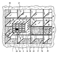
- The sole Figure of the drawing shows, in a diagrammatic perspective view, a barrier according to the invention.
- The barrier as shown in the Figure, for penetrating conduits through a
wall opening 1 comprises anenclosure body 3 which can be disposed in thewall opening 1 and comprises a plurality of throughgoing receiving channels, forinstance enclosure body 3 is assembled from plates, forinstance enclosure body 3. In the illustrated embodiment, plates having slots, forinstance enclosure body 3 is simply plugged together from these plates. Thereby, assembly at the application site is easily possible, and the enclosure body can be handled, stored, and shipped in the disassembled state in a space-saving manner. - The illustrated barrier contains furthermore a heat-
resistant grid 17 adapted to be fitted into and fill completely thewall opening 1, the mesh openings of the grid forming throughgoing insertion channels, forinstance enclosure bodies 3, and being dimensioned accordingly. In this connection, the dimensions of the insertion channels, forinstance enclosure bodies 3 so that theenclosure body 3 can be shifted with little play into an insertion channel. In the Figure, it is indicated that theenclosure body 3 illustrated there is just being shifted into theinsertion channel 21. - Due to the small clearance between enclosure body and insertion channel, a good seal between the
enclosure body 3 and thegrid 17 is made possible, and the best possible combination of space economy and strength is obtained. - The non-needed mesh openings are adapted to be closed by fire-restraining covers, such as 23, 25. In the Figure, the case is illustrated that the width of the
wall opening 1 is not exactly a multiple of the width of the mesh openings; accordingly, the mesh openings which are disposed at the right-hand margin of thegrid 17, forinstance 27, are narrower than the remaining mesh openings which are disposed more to the left. Accordingly, also the fire-restraining covers 25 for thenarrower mesh openings 27 are correspondingly narrower than thecovers 23 for the other mesh openings. - In the illustrated embodiment, the receiving channels of the
enclosure body 3 can be closed, if not in use, by means of fire-restraining covers, such as 29. Thereby, the fire protection action of the fire protection material need be dimensioned only for the case that the major parts of the cross-sections of the receiving channels, forinstance - The fire-restraining covers 23, 25, 29 can consist at least partially of a fire protection material which, under influence of a fire, forms an obstacle against the spreading of the fire. Thereby, the barrier action of the covers can be maintained still for a longer period of time in the case of a fire.
- The
grid 17 has a strength which is sufficient for the reception of a plurality ofenclosure bodies 3 with conduits therein. Normally, the strength of thegrid 17 will have to be dimensioned for the case that all insertion channels, such as 19, 21, are filled withenclosure bodies 3 with conduits disposed therein. Such a strength can be readily obtained by a corresponding selection of the construction materials used for thegrid 17. Moreover, thegrid 17 should be designed so that it will be distorted as little as possible under the influence of a fire. Depending upon the material of the grid, this can be aimed at in different ways; measures which are suitable therefor are known to skilled people. More particularly, an extraordinarily high resistivity and shape consistency can be obtained if thegrid 17 consists at least partly of ceramic material. For instance, commercial ceramic construction plates are suitable which consist essentially of calcium silicate. Similar good results can be also obtained if thegrid 17 consists at least partly of suitably selected fire-resistant metal. - The useful life of the
grid 17 under the influence of a fire can be considerably increased if thegrid 17 consists at least partly of fire protection material. In the illustrated embodiment, particularly high fire protection action and a long useful life are due to the fact that the grid consists of metal with a coating of fire protection material. Material of that kind is commercially available; for instance, particularly suitable is the material which is distributed under the designation "CS 195" by the company 3M Deutschland GmbH, Neuss. In the illustrated embodiment, thegrid 17 is assembled from plates, forinstance grid 17 can be manufactured conveniently. In the illustrated embodiment, the assembly, moreover, is further facilitated in that slotted plates are used, whereby thegrid 17 can be simply plugged together in the slots, forinstance grids 17 in store in a disassembled and thus space-saving condition. For these properties, it is advantageous if thegrid 17 is free of a frame, as illustrated. The absence of the frame moreover facilitates the introduction of thegrid 17 into thewall opening 1. However, also a grid may be used, of course, which has a peripheral frame. - Normally, it is essential that the wall opening 1 remains completely closed and sealed as long as possible in the case of a fire so that fire and smoke cannot penetrate and chimney-like draft phenomena are avoided. Therefore, any gaps and interstices should normally be filled with fire protection mass 39 (caulk or putty) for instance, particularly in the contact areas between
grid 17 andwall opening 1 and furthermore, in the areas where the plates, forinstance grid 17 and theenclosure body 3 are plugged together, and between theenclosure body 3 and the walls of theinsertion channel 21 in which it is received. - As a fire protection material, a material may be advantageously used which will expand under the influence of a fire and in doing so, will convert into a sealing char-like material of low heat conductivity. Preferably, this is combined with evolving water and/or consuming heat by means of an endothermic reaction. Materials of that kind are known. For instance, they may contain particles of alkaline earth metal silicate in an elastomeric base material. Particularly suitable materials of that kind are distributed by the company 3M Deutschland GmbH, Neuss, as Type FS-195AA which predominantly is characterized by its increase in volume (the intumescent action).
- As fire protection materials which, under the influence of a fire will consume heat by means of an endothermic chemical reaction and additionally evolves water which has a cooling action are those materials which contain ceramic fibers intermixed with fine particles of aluminum trihydrate. Particularly suitable are the fire protection materials of that kind which are distributed by the company 3M Deutschland, Neuss, as Type E5, which is predominantly characterized by its heat-consuming activity.
- The barrier according to the invention can be particularly easily provided in a disassembled condition as a space-saving construction kit. This is very advantageous for storage and shipping.
Claims (19)
characterized in that
the said barrier comprises a fire-resistant grid (17) dimensioned to fill out the wall opening (1), said grid (17) comprising a plurality of insertion channels (19, 21, 23, 25) forming a mesh of openings (27), the dimensions of each insertion channel being adapted to the dimensions of the body (3) so that the body (3) is insertable into an insertion channel (19, 21, 23, 25) with a small clearance, whereby non-needed mesh openings can be closed by fire-restraining covers (23, 25), said grid (17) having a strengh which is sufficient to receive a plurality of the bodies (3) with conduits therein.
Applications Claiming Priority (2)
| Application Number | Priority Date | Filing Date | Title |
|---|---|---|---|
| DE19863641914 DE3641914A1 (en) | 1986-12-09 | 1986-12-09 | FIRE-RETARDANT SEPARATION FOR LEADING PIPES THROUGH A WALL OPENING |
| DE3641914 | 1986-12-09 |
Publications (2)
| Publication Number | Publication Date |
|---|---|
| EP0271248A1 EP0271248A1 (en) | 1988-06-15 |
| EP0271248B1 true EP0271248B1 (en) | 1991-01-02 |
Family
ID=6315727
Family Applications (1)
| Application Number | Title | Priority Date | Filing Date |
|---|---|---|---|
| EP87310348A Expired - Lifetime EP0271248B1 (en) | 1986-12-09 | 1987-11-24 | Fire-restraining barrier for the penetration of conduits through a wall opening |
Country Status (4)
| Country | Link |
|---|---|
| EP (1) | EP0271248B1 (en) |
| JP (1) | JPS63158378A (en) |
| DE (1) | DE3641914A1 (en) |
| FI (1) | FI84392C (en) |
Families Citing this family (7)
| Publication number | Priority date | Publication date | Assignee | Title |
|---|---|---|---|---|
| DE3803585C2 (en) * | 1988-02-06 | 1997-02-06 | Minnesota Mining & Mfg | Fire-retardant bulkhead for routing cables through a wall opening |
| DE3821969C1 (en) * | 1988-06-29 | 1990-02-01 | Michael Dr. 8000 Muenchen De Spaeth | |
| SE460509B (en) * | 1988-08-01 | 1989-10-16 | Studsvik Fire Seal Ab | DEVICE FOR CABLE PIPE |
| GB2247997B (en) * | 1990-09-15 | 1994-09-21 | Environmental Seals Ltd | Improvements in and relating to fire proofed conduits and conduit fittings for electrical cabling |
| JPH0748277Y2 (en) * | 1991-11-29 | 1995-11-08 | 鹿島建設株式会社 | Penetration structure such as duct between lower beams |
| JPH08218610A (en) * | 1995-02-20 | 1996-08-27 | Taisei Corp | Filler support for through hole |
| DE202015102280U1 (en) * | 2015-05-05 | 2016-05-10 | Conta-Clip Verbindungstechnik Gmbh | Arrangement with a wall feedthrough for several cables and kit |
Citations (1)
| Publication number | Priority date | Publication date | Assignee | Title |
|---|---|---|---|---|
| US4419535A (en) * | 1981-07-31 | 1983-12-06 | Hara Robert J O | Multi-cable conduit for floors and walls |
Family Cites Families (8)
| Publication number | Priority date | Publication date | Assignee | Title |
|---|---|---|---|---|
| SE391082B (en) * | 1973-01-15 | 1977-01-31 | H E Anderberg | HOW TO ACCOMPANY A FIRE AND CONSEQUENTIAL HIGH TEMPERATURE FIRE, GAS AND LIQUID SAFE IMPLEMENTATION OF LEADERS |
| DE2614893A1 (en) * | 1976-04-06 | 1977-10-20 | Mabag Luft & Klimatechnik | Mobile or stationary fire barrier e.g. a door - consists of flame-retarding material and incorporates water-filled plastics containers which disintegrate at elevated temp. |
| DE2654806A1 (en) * | 1976-12-03 | 1978-06-15 | Nils Brendel Tech Spezialverfa | Sealed wall penetration for pipes and cables - has flexible extruded frame and axial bolt with expanding wedges |
| WO1980002086A1 (en) * | 1979-03-23 | 1980-10-02 | J Pedlow | Fire protective mastic and fire stop |
| AU532560B2 (en) * | 1979-06-26 | 1983-10-06 | Variable Kinetic Drives Ltd. | Transmission |
| US4304079A (en) * | 1980-01-11 | 1981-12-08 | Bell Telephone Laboratories, Incorporated | Fire retardant modular floor penetration structure |
| US4364210A (en) * | 1980-05-29 | 1982-12-21 | Minnesota Mining And Manufacturing Company | Fire barrier device |
| AT382045B (en) * | 1984-02-10 | 1986-12-29 | Doepfl Rudolf Gmbh | DEVICE FOR FIRE-INSULATED THROUGHOUT OF CABLES OR THE LIKE. THROUGH A WALL OPENING |
-
1986
- 1986-12-09 DE DE19863641914 patent/DE3641914A1/en active Granted
-
1987
- 1987-11-24 EP EP87310348A patent/EP0271248B1/en not_active Expired - Lifetime
- 1987-12-03 FI FI875341A patent/FI84392C/en not_active IP Right Cessation
- 1987-12-08 JP JP62310786A patent/JPS63158378A/en active Pending
Patent Citations (1)
| Publication number | Priority date | Publication date | Assignee | Title |
|---|---|---|---|---|
| US4419535A (en) * | 1981-07-31 | 1983-12-06 | Hara Robert J O | Multi-cable conduit for floors and walls |
Also Published As
| Publication number | Publication date |
|---|---|
| EP0271248A1 (en) | 1988-06-15 |
| FI875341A0 (en) | 1987-12-03 |
| DE3641914A1 (en) | 1988-07-14 |
| FI84392C (en) | 1991-11-25 |
| FI875341A (en) | 1988-06-10 |
| DE3641914C2 (en) | 1988-12-01 |
| FI84392B (en) | 1991-08-15 |
| JPS63158378A (en) | 1988-07-01 |
Similar Documents
| Publication | Publication Date | Title |
|---|---|---|
| EP0271248B1 (en) | Fire-restraining barrier for the penetration of conduits through a wall opening | |
| US5067676A (en) | System for the prevention of fire, water or flue gas and the like from propagating along cables | |
| US4376230A (en) | Cable duct | |
| DE60103649T2 (en) | FIRE PROTECTION COVER PLATE FOR ELECTRICAL SOCKETS AND SWITCHES | |
| DE3268263D1 (en) | Intumescent flame retardant compositions | |
| GB9209043D0 (en) | Trunking | |
| US20030160399A1 (en) | Method and apparatus for providing a modular shielded enclosure | |
| US4144688A (en) | Fire resistant seals | |
| GB2114983B (en) | Intumescent fire retardant compositions | |
| GB2150142B (en) | Fire retardant polyolefin composition | |
| GB2145624B (en) | Fire fighting bucket assembly | |
| US6789363B1 (en) | Security room for information technology facilities | |
| US6023893A (en) | Movable partition wall | |
| EP0225107A2 (en) | Fire-retardant wall penetration for electrical cables | |
| JPH0326764Y2 (en) | ||
| US20190374799A1 (en) | Fire protection element | |
| KR102388257B1 (en) | Organizer for multi-tap | |
| JP3583917B2 (en) | Fire protection structure | |
| JPS60136687A (en) | Structure of cable penetrating section | |
| CA2013227C (en) | System for the prevention of fire, water or (flue) gas and the like from propagating along cables | |
| JP2006115625A (en) | Construction method for fire protection construction of cable penetrating portion in building, and fire protection construction of cable penetrating portion in building | |
| GB2293208A (en) | Fire resistant safe | |
| JPH0229767Y2 (en) | ||
| JP2022066683A (en) | Seal structure of cable tray penetration part | |
| DE3369855D1 (en) | Flame retardant polystyrene and poly(para-methylstyrene) compositions containing octahalobiphthalyl |
Legal Events
| Date | Code | Title | Description |
|---|---|---|---|
| PUAI | Public reference made under article 153(3) epc to a published international application that has entered the european phase |
Free format text: ORIGINAL CODE: 0009012 |
|
| AK | Designated contracting states |
Kind code of ref document: A1 Designated state(s): BE FR GB IT NL |
|
| 17P | Request for examination filed |
Effective date: 19881118 |
|
| 17Q | First examination report despatched |
Effective date: 19890412 |
|
| ITF | It: translation for a ep patent filed |
Owner name: BARZANO' E ZANARDO ROMA S.P.A. |
|
| GRAA | (expected) grant |
Free format text: ORIGINAL CODE: 0009210 |
|
| AK | Designated contracting states |
Kind code of ref document: B1 Designated state(s): BE FR GB IT NL |
|
| ET | Fr: translation filed | ||
| PLBE | No opposition filed within time limit |
Free format text: ORIGINAL CODE: 0009261 |
|
| STAA | Information on the status of an ep patent application or granted ep patent |
Free format text: STATUS: NO OPPOSITION FILED WITHIN TIME LIMIT |
|
| 26N | No opposition filed | ||
| PGFP | Annual fee paid to national office [announced via postgrant information from national office to epo] |
Ref country code: GB Payment date: 19941026 Year of fee payment: 8 |
|
| PG25 | Lapsed in a contracting state [announced via postgrant information from national office to epo] |
Ref country code: GB Effective date: 19951124 |
|
| GBPC | Gb: european patent ceased through non-payment of renewal fee |
Effective date: 19951124 |
|
| PGFP | Annual fee paid to national office [announced via postgrant information from national office to epo] |
Ref country code: FR Payment date: 19981030 Year of fee payment: 12 |
|
| PGFP | Annual fee paid to national office [announced via postgrant information from national office to epo] |
Ref country code: NL Payment date: 19981109 Year of fee payment: 12 |
|
| PGFP | Annual fee paid to national office [announced via postgrant information from national office to epo] |
Ref country code: BE Payment date: 19981125 Year of fee payment: 12 |
|
| PG25 | Lapsed in a contracting state [announced via postgrant information from national office to epo] |
Ref country code: BE Free format text: LAPSE BECAUSE OF NON-PAYMENT OF DUE FEES Effective date: 19991130 |
|
| BERE | Be: lapsed |
Owner name: MINNESOTA MINING AND MFG CY Effective date: 19991130 |
|
| PG25 | Lapsed in a contracting state [announced via postgrant information from national office to epo] |
Ref country code: NL Free format text: LAPSE BECAUSE OF NON-PAYMENT OF DUE FEES Effective date: 20000601 |
|
| PG25 | Lapsed in a contracting state [announced via postgrant information from national office to epo] |
Ref country code: FR Free format text: LAPSE BECAUSE OF NON-PAYMENT OF DUE FEES Effective date: 20000731 |
|
| NLV4 | Nl: lapsed or anulled due to non-payment of the annual fee |
Effective date: 20000601 |
|
| REG | Reference to a national code |
Ref country code: FR Ref legal event code: ST |
|
| PG25 | Lapsed in a contracting state [announced via postgrant information from national office to epo] |
Ref country code: IT Free format text: LAPSE BECAUSE OF NON-PAYMENT OF DUE FEES;WARNING: LAPSES OF ITALIAN PATENTS WITH EFFECTIVE DATE BEFORE 2007 MAY HAVE OCCURRED AT ANY TIME BEFORE 2007. THE CORRECT EFFECTIVE DATE MAY BE DIFFERENT FROM THE ONE RECORDED. Effective date: 20051124 |