EP0271090A2 - Recording apparatus - Google Patents
Recording apparatus Download PDFInfo
- Publication number
- EP0271090A2 EP0271090A2 EP87118269A EP87118269A EP0271090A2 EP 0271090 A2 EP0271090 A2 EP 0271090A2 EP 87118269 A EP87118269 A EP 87118269A EP 87118269 A EP87118269 A EP 87118269A EP 0271090 A2 EP0271090 A2 EP 0271090A2
- Authority
- EP
- European Patent Office
- Prior art keywords
- recording
- ink
- platen
- discharge ports
- recording apparatus
- Prior art date
- Legal status (The legal status is an assumption and is not a legal conclusion. Google has not performed a legal analysis and makes no representation as to the accuracy of the status listed.)
- Granted
Links
Images


Classifications
-
- B—PERFORMING OPERATIONS; TRANSPORTING
- B41—PRINTING; LINING MACHINES; TYPEWRITERS; STAMPS
- B41J—TYPEWRITERS; SELECTIVE PRINTING MECHANISMS, i.e. MECHANISMS PRINTING OTHERWISE THAN FROM A FORME; CORRECTION OF TYPOGRAPHICAL ERRORS
- B41J2/00—Typewriters or selective printing mechanisms characterised by the printing or marking process for which they are designed
- B41J2/005—Typewriters or selective printing mechanisms characterised by the printing or marking process for which they are designed characterised by bringing liquid or particles selectively into contact with a printing material
- B41J2/01—Ink jet
- B41J2/17—Ink jet characterised by ink handling
- B41J2/175—Ink supply systems ; Circuit parts therefor
- B41J2/17503—Ink cartridges
- B41J2/1752—Mounting within the printer
- B41J2/17523—Ink connection
-
- B—PERFORMING OPERATIONS; TRANSPORTING
- B41—PRINTING; LINING MACHINES; TYPEWRITERS; STAMPS
- B41J—TYPEWRITERS; SELECTIVE PRINTING MECHANISMS, i.e. MECHANISMS PRINTING OTHERWISE THAN FROM A FORME; CORRECTION OF TYPOGRAPHICAL ERRORS
- B41J11/00—Devices or arrangements of selective printing mechanisms, e.g. ink-jet printers or thermal printers, for supporting or handling copy material in sheet or web form
- B41J11/02—Platens
- B41J11/14—Platen-shift mechanisms; Driving gear therefor
-
- B—PERFORMING OPERATIONS; TRANSPORTING
- B41—PRINTING; LINING MACHINES; TYPEWRITERS; STAMPS
- B41J—TYPEWRITERS; SELECTIVE PRINTING MECHANISMS, i.e. MECHANISMS PRINTING OTHERWISE THAN FROM A FORME; CORRECTION OF TYPOGRAPHICAL ERRORS
- B41J2/00—Typewriters or selective printing mechanisms characterised by the printing or marking process for which they are designed
- B41J2/005—Typewriters or selective printing mechanisms characterised by the printing or marking process for which they are designed characterised by bringing liquid or particles selectively into contact with a printing material
- B41J2/01—Ink jet
- B41J2/135—Nozzles
- B41J2/165—Preventing or detecting of nozzle clogging, e.g. cleaning, capping or moistening for nozzles
- B41J2/16517—Cleaning of print head nozzles
- B41J2/1652—Cleaning of print head nozzles by driving a fluid through the nozzles to the outside thereof, e.g. by applying pressure to the inside or vacuum at the outside of the print head
-
- B—PERFORMING OPERATIONS; TRANSPORTING
- B41—PRINTING; LINING MACHINES; TYPEWRITERS; STAMPS
- B41J—TYPEWRITERS; SELECTIVE PRINTING MECHANISMS, i.e. MECHANISMS PRINTING OTHERWISE THAN FROM A FORME; CORRECTION OF TYPOGRAPHICAL ERRORS
- B41J2/00—Typewriters or selective printing mechanisms characterised by the printing or marking process for which they are designed
- B41J2/005—Typewriters or selective printing mechanisms characterised by the printing or marking process for which they are designed characterised by bringing liquid or particles selectively into contact with a printing material
- B41J2/01—Ink jet
- B41J2/135—Nozzles
- B41J2/165—Preventing or detecting of nozzle clogging, e.g. cleaning, capping or moistening for nozzles
- B41J2/16585—Preventing or detecting of nozzle clogging, e.g. cleaning, capping or moistening for nozzles for paper-width or non-reciprocating print heads
-
- B—PERFORMING OPERATIONS; TRANSPORTING
- B41—PRINTING; LINING MACHINES; TYPEWRITERS; STAMPS
- B41J—TYPEWRITERS; SELECTIVE PRINTING MECHANISMS, i.e. MECHANISMS PRINTING OTHERWISE THAN FROM A FORME; CORRECTION OF TYPOGRAPHICAL ERRORS
- B41J2/00—Typewriters or selective printing mechanisms characterised by the printing or marking process for which they are designed
- B41J2/005—Typewriters or selective printing mechanisms characterised by the printing or marking process for which they are designed characterised by bringing liquid or particles selectively into contact with a printing material
- B41J2/01—Ink jet
- B41J2/17—Ink jet characterised by ink handling
- B41J2/1714—Conditioning of the outside of ink supply systems, e.g. inkjet collector cleaning, ink mist removal
-
- B—PERFORMING OPERATIONS; TRANSPORTING
- B41—PRINTING; LINING MACHINES; TYPEWRITERS; STAMPS
- B41J—TYPEWRITERS; SELECTIVE PRINTING MECHANISMS, i.e. MECHANISMS PRINTING OTHERWISE THAN FROM A FORME; CORRECTION OF TYPOGRAPHICAL ERRORS
- B41J2/00—Typewriters or selective printing mechanisms characterised by the printing or marking process for which they are designed
- B41J2/005—Typewriters or selective printing mechanisms characterised by the printing or marking process for which they are designed characterised by bringing liquid or particles selectively into contact with a printing material
- B41J2/01—Ink jet
- B41J2/17—Ink jet characterised by ink handling
- B41J2/175—Ink supply systems ; Circuit parts therefor
- B41J2/17503—Ink cartridges
- B41J2/17513—Inner structure
-
- B—PERFORMING OPERATIONS; TRANSPORTING
- B41—PRINTING; LINING MACHINES; TYPEWRITERS; STAMPS
- B41J—TYPEWRITERS; SELECTIVE PRINTING MECHANISMS, i.e. MECHANISMS PRINTING OTHERWISE THAN FROM A FORME; CORRECTION OF TYPOGRAPHICAL ERRORS
- B41J2/00—Typewriters or selective printing mechanisms characterised by the printing or marking process for which they are designed
- B41J2/005—Typewriters or selective printing mechanisms characterised by the printing or marking process for which they are designed characterised by bringing liquid or particles selectively into contact with a printing material
- B41J2/01—Ink jet
- B41J2/17—Ink jet characterised by ink handling
- B41J2/175—Ink supply systems ; Circuit parts therefor
- B41J2/17503—Ink cartridges
- B41J2/1752—Mounting within the printer
-
- B—PERFORMING OPERATIONS; TRANSPORTING
- B41—PRINTING; LINING MACHINES; TYPEWRITERS; STAMPS
- B41J—TYPEWRITERS; SELECTIVE PRINTING MECHANISMS, i.e. MECHANISMS PRINTING OTHERWISE THAN FROM A FORME; CORRECTION OF TYPOGRAPHICAL ERRORS
- B41J29/00—Details of, or accessories for, typewriters or selective printing mechanisms not otherwise provided for
- B41J29/02—Framework
-
- B—PERFORMING OPERATIONS; TRANSPORTING
- B41—PRINTING; LINING MACHINES; TYPEWRITERS; STAMPS
- B41J—TYPEWRITERS; SELECTIVE PRINTING MECHANISMS, i.e. MECHANISMS PRINTING OTHERWISE THAN FROM A FORME; CORRECTION OF TYPOGRAPHICAL ERRORS
- B41J29/00—Details of, or accessories for, typewriters or selective printing mechanisms not otherwise provided for
- B41J29/377—Cooling or ventilating arrangements
-
- G—PHYSICS
- G03—PHOTOGRAPHY; CINEMATOGRAPHY; ANALOGOUS TECHNIQUES USING WAVES OTHER THAN OPTICAL WAVES; ELECTROGRAPHY; HOLOGRAPHY
- G03G—ELECTROGRAPHY; ELECTROPHOTOGRAPHY; MAGNETOGRAPHY
- G03G21/00—Arrangements not provided for by groups G03G13/00 - G03G19/00, e.g. cleaning, elimination of residual charge
- G03G21/16—Mechanical means for facilitating the maintenance of the apparatus, e.g. modular arrangements
- G03G21/1604—Arrangement or disposition of the entire apparatus
- G03G21/1623—Means to access the interior of the apparatus
- G03G21/1628—Clamshell type
-
- G—PHYSICS
- G03—PHOTOGRAPHY; CINEMATOGRAPHY; ANALOGOUS TECHNIQUES USING WAVES OTHER THAN OPTICAL WAVES; ELECTROGRAPHY; HOLOGRAPHY
- G03G—ELECTROGRAPHY; ELECTROPHOTOGRAPHY; MAGNETOGRAPHY
- G03G21/00—Arrangements not provided for by groups G03G13/00 - G03G19/00, e.g. cleaning, elimination of residual charge
- G03G21/16—Mechanical means for facilitating the maintenance of the apparatus, e.g. modular arrangements
- G03G21/1642—Mechanical means for facilitating the maintenance of the apparatus, e.g. modular arrangements for connecting the different parts of the apparatus
- G03G21/1647—Mechanical connection means
-
- G—PHYSICS
- G03—PHOTOGRAPHY; CINEMATOGRAPHY; ANALOGOUS TECHNIQUES USING WAVES OTHER THAN OPTICAL WAVES; ELECTROGRAPHY; HOLOGRAPHY
- G03G—ELECTROGRAPHY; ELECTROPHOTOGRAPHY; MAGNETOGRAPHY
- G03G21/00—Arrangements not provided for by groups G03G13/00 - G03G19/00, e.g. cleaning, elimination of residual charge
- G03G21/20—Humidity or temperature control also ozone evacuation; Internal apparatus environment control
- G03G21/206—Conducting air through the machine, e.g. for cooling, filtering, removing gases like ozone
-
- H—ELECTRICITY
- H04—ELECTRIC COMMUNICATION TECHNIQUE
- H04N—PICTORIAL COMMUNICATION, e.g. TELEVISION
- H04N1/00—Scanning, transmission or reproduction of documents or the like, e.g. facsimile transmission; Details thereof
- H04N1/00519—Constructional details not otherwise provided for, e.g. housings, covers
- H04N1/00525—Providing a more compact apparatus, e.g. sheet discharge tray in cover
-
- H—ELECTRICITY
- H04—ELECTRIC COMMUNICATION TECHNIQUE
- H04N—PICTORIAL COMMUNICATION, e.g. TELEVISION
- H04N1/00—Scanning, transmission or reproduction of documents or the like, e.g. facsimile transmission; Details thereof
- H04N1/00519—Constructional details not otherwise provided for, e.g. housings, covers
- H04N1/00543—Allowing easy access, e.g. for maintenance or in case of paper jam
-
- H—ELECTRICITY
- H04—ELECTRIC COMMUNICATION TECHNIQUE
- H04N—PICTORIAL COMMUNICATION, e.g. TELEVISION
- H04N1/00—Scanning, transmission or reproduction of documents or the like, e.g. facsimile transmission; Details thereof
- H04N1/00519—Constructional details not otherwise provided for, e.g. housings, covers
- H04N1/00551—Top covers or the like
- H04N1/00554—Latches or hinges therefor
-
- H—ELECTRICITY
- H04—ELECTRIC COMMUNICATION TECHNIQUE
- H04N—PICTORIAL COMMUNICATION, e.g. TELEVISION
- H04N1/00—Scanning, transmission or reproduction of documents or the like, e.g. facsimile transmission; Details thereof
- H04N1/00976—Arrangements for regulating environment, e.g. removing static electricity
-
- G—PHYSICS
- G03—PHOTOGRAPHY; CINEMATOGRAPHY; ANALOGOUS TECHNIQUES USING WAVES OTHER THAN OPTICAL WAVES; ELECTROGRAPHY; HOLOGRAPHY
- G03G—ELECTROGRAPHY; ELECTROPHOTOGRAPHY; MAGNETOGRAPHY
- G03G2221/00—Processes not provided for by group G03G2215/00, e.g. cleaning or residual charge elimination
- G03G2221/16—Mechanical means for facilitating the maintenance of the apparatus, e.g. modular arrangements and complete machine concepts
- G03G2221/1645—Mechanical means for facilitating the maintenance of the apparatus, e.g. modular arrangements and complete machine concepts for conducting air through the machine, e.g. cooling
-
- G—PHYSICS
- G03—PHOTOGRAPHY; CINEMATOGRAPHY; ANALOGOUS TECHNIQUES USING WAVES OTHER THAN OPTICAL WAVES; ELECTROGRAPHY; HOLOGRAPHY
- G03G—ELECTROGRAPHY; ELECTROPHOTOGRAPHY; MAGNETOGRAPHY
- G03G2221/00—Processes not provided for by group G03G2215/00, e.g. cleaning or residual charge elimination
- G03G2221/16—Mechanical means for facilitating the maintenance of the apparatus, e.g. modular arrangements and complete machine concepts
- G03G2221/1651—Mechanical means for facilitating the maintenance of the apparatus, e.g. modular arrangements and complete machine concepts for connecting the different parts
-
- G—PHYSICS
- G03—PHOTOGRAPHY; CINEMATOGRAPHY; ANALOGOUS TECHNIQUES USING WAVES OTHER THAN OPTICAL WAVES; ELECTROGRAPHY; HOLOGRAPHY
- G03G—ELECTROGRAPHY; ELECTROPHOTOGRAPHY; MAGNETOGRAPHY
- G03G2221/00—Processes not provided for by group G03G2215/00, e.g. cleaning or residual charge elimination
- G03G2221/16—Mechanical means for facilitating the maintenance of the apparatus, e.g. modular arrangements and complete machine concepts
- G03G2221/1672—Paper handling
-
- G—PHYSICS
- G03—PHOTOGRAPHY; CINEMATOGRAPHY; ANALOGOUS TECHNIQUES USING WAVES OTHER THAN OPTICAL WAVES; ELECTROGRAPHY; HOLOGRAPHY
- G03G—ELECTROGRAPHY; ELECTROPHOTOGRAPHY; MAGNETOGRAPHY
- G03G2221/00—Processes not provided for by group G03G2215/00, e.g. cleaning or residual charge elimination
- G03G2221/16—Mechanical means for facilitating the maintenance of the apparatus, e.g. modular arrangements and complete machine concepts
- G03G2221/1678—Frame structures
- G03G2221/1687—Frame structures using opening shell type machines, e.g. pivoting assemblies
Definitions
- This invention relates to a recording apparatus and an ink cartridge in use for the apparatus, and more particularly to a recording apparatus having an ink jet recording head using ink to effect recording (an ink jet recording apparatus).
- the ink jet recording system As recording means used in a recording apparatus, the ink jet recording system has numerous advantages such as very small noise during recording and capability of effecting recording on plain paper, and has been attracting more and more attention in recent years.
- a recording apparatus which reads image information from a medium (an original) bearing information and effects a series of image processing operations in which the image information is recorded on a recording medium such as paper is now an apparatus indispensable in the information processing system.
- Such a recording apparatus also has numerous advantages such as very small noise during recording and capability of effecting recording on plain paper and therefore, the ink jet recording systems have been attracting more and more attention.
- the ink jet recording system called the on-demand type which effects ink discharge during recording by the utilization of either a piezoelectric element or a magnetostrictive element which is an electro-mechanical converting element or an electro-thermal converting element has a great advantage that it does not require means for collecting unnecessary ink and a high voltage source for deflection, because it consumes ink only when necessary for recording.
- the ink jet recording apparatus which generally uses liquid as a recording agent, may experience the clogging or the like of ink in recording means such as a head and thus, improved operability of maintenance of the recording means is desired.
- recording mediums such as paper may jam in the conveyance path and thus, improved operability of so-called jam treatment is desired.
- the ink jet recording apparatus thus has various advantages, dust or paper powder of recording paper has adhered to the discharge ports of the recording head to cause clogging of such ports or cause mixing of bubbles with the interior of the discharge ports, or in the on-demand type ink jet recording apparatus, the frequency of use of a number of nozzles arranged in the recording head is not uniform and therefore, irregularity of discharge conditions has sometimes been caused by an increase in the viscosity of ink. Also, ink has sometimes adhered to a recording medium when it has remained on the end surface of the recording head in which discharge ports open.
- the discharge restoring operation it is requisite to effect a suitable operation for eliminating these various factors which degrade the quality of recording (hereinafter referred to as the discharge restoring operation).
- an ink jet recording apparatus particularly an ink jet recording apparatus having a so-called full multi-type recording head in which discharge ports are arranged in a range corresponding to the width of the recording medium
- a platen for controlling the recording surface is provided in proximately opposed relationship with the discharge ports over the full range in which the discharge ports are arranged and therefore, it has been difficult to secure a large work space when effecting said discharge restoring operation, without making the apparatus bulky.
- the platen for controlling the recording surface is provided in proximately opposed relationship with the discharge ports over the full range in which the discharge ports are arranged, and this gives rise to the necessity of replacing the platen with the restoring member when effecting said discharge restoring operation.
- the restoring member receives ink during the discharge restoring operation, etc. and therefore, it is desirable to provide it with an ink absorbing member formed of a water-absorbent porous material.
- an ink absorbing member is limited in its ink absorbing capacity (the amount of ink absorbed) and therefore, it is preferable to interchange it at suitable chances.
- another member required to be interchanged in the ink jet recording apparatus is an ink tank for ink supply if the ink tank is of the interchangeable type.
- the ink jet recording apparatus when the interchange of both of the restoring member and the ink tank becomes necessary, two stages of discrete operations must be performed during the use.
- It is an object of the present invention to provide a recording apparatus being characterized by the provision of an upper unit having recording means having ink discharge ports for discharging ink for effecting recording on the recording medium in response to information, and at least a portion of the electric circuit means of the apparatus, a lower unit having a platen for maintaining the recording medium in the recording station by the recording means, said lower unit being capable of being spaced apart relative to said upper unit, and conveying means for conveying said recording medium to said recording station, said upper unit and said lower unit being capable of being spaced apart and opened in the recording station by said recording means.
- It is an object of the present invention to provide a recording apparatus being provided with a first unit having recording means for discharging ink for effecting recording on the recording medium in response to information, a second unit having a platen for maintaining said recording medium in the recording station by said recording means, and ink storing means storing therein the ink to be supplied to said recording means, said second unit being capable of being spaced apart relative to said first unit, conveying means for conveying said recording medium to said recording station, and an ink supply connecting member displaceable in response to the spacing apart of said first unit and said second unit and connecting said recording means to said ink storing means to supply the ink from said ink storing means to said recording means, said first unit and said second unit being capable of being spaced apart and opened in the recording station by said recording means.
- the upper unit and the lower unit are capable of being spaced apart and opened in the recording station, whereby the space available to effect the maintenance of the recording means can be made large and the conveyance path can be opened.
- the first unit and the second unit are capable of being spaced apart and opened in the recording station, whereby the space available to effect the maintenance of the recording means can be made large and the conveyance path can be opened.
- the ink supply connecting member is displaceable, the spacing apart of the first and second units is permitted, for example, without involving the separation of the ink supplying system.
- the platen if a driving member is suitably driven in the discharge restoring operation, the platen will leave the position opposed to the recording head and therefore, a work space will be secured near the recording head.
- the platen and the joining member are operatively associated with each other and replace each other in position to become opposed to the discharge ports, so that where for example, the joining member is a restoring member, a reliable discharge restoring operation becomes possible without involving great displacement of the platen and joining member.
- the platen and the receiving member are operatively associated with each other and replace each other in position to become opposed to the discharge ports and therefore, without involving their great displacement, the discharge restoring operation of the recording head becomes possible. Also, since the storing means and the receiving member are provided as a unit in the holding member, the interchanging work is simplified and saving of the space can be achieved.
- the platen can be used also as a lid member for covering the receiving member when the cartridge is removed from the apparatus body.
- the ink jet recording means and the image input means are constructed integrally with each other, whereby there can be provided a recording apparatus which is compact and high in operability while making the most of the advantages of the ink jet recording means.
- the respective units are capable of being spaced apart and opened in the recording station, whereby the space available to effect the maintenance of the recording means can be made large and the conveyance path can be opened.
- the ink supply connecting member is displaceable and thus, the spacing apart of the units is permitted, for example, without involving the separation of the ink supplying system.
- Figure 1 is a perspective view showing an example of the outer construction of an ink jet recording apparatus which is a preferred embodiment of the present invention
- Figure 2 is a perspective view showing the ink jet recording apparatus with its outer cover removed for convenience.
- the reference numeral 1 designates a body unit portion having an upper unit 1a as a first unit and a lower unit 1b as a second unit.
- the upper unit 1a is pivotable up and down relative to the lower unit 1b about a hinge 11, as shown, for example, in Figure 4.
- the upper unit 1a need not always be made pivotable about the hinge 11.
- the upper unit 1a is provided with a recording head 101, an electric circuit portion 103, a fan 150, an upper discharge roller 115a, an upper conveyor roller 113a, a paper guide 201 and a paper supply roller 111 which will be described in detail.
- the lower unit 1b is provided with a platen 203, an ink absorbing member 235, an ink tank 231, a paper cassette 221, a paper discharge tray 9A and idlers 213, 215.
- the reference numeral 5 denotes a cover disposed over the upper side of the body unit portion 1.
- the cover 5 is provided with an operating portion 7 in which there are disposed various command switches 7a and 7b such as on-line switches with a host apparatus H and a display device 7C for effecting the mode display.
- the reference numeral 9 designates a discharge port formed in one side of the apparatus. Recording mediums S on which recording has been effected are piled on the discharge tray 9A through the discharge port 9.
- Figure 2 is a perspective view showing the apparatus of Figure 1 with the cover 5 removed to illustrate the interior construction of the apparatus of Figure 1
- Figure 3 is a side cross-sectional view of the apparatus of Figure 1.
- the reference numeral 101 designates an ink jet recording head disposed near the discharge port 9.
- the ink jet recording head 101 is in the form of the so-called full multi-type wherein nozzles 101a are arranged, for example, at a density of 16 nozzles per 1 mm, over a range corresponding to the full recording width (e.g., recording paper of format A4) of the present apparatus.
- electro-mechanical converting elements (not shown) or electro-thermal converting elements (not shown) are disposed at appropriate locations in the ink flow paths such as the nozzles and discharge energy is caused to act on ink in response to the supply of a driving signal from the host apparatus H corresponding to an image to be recorded, whereby ink is discharged from the discharge ports 101b, but the latter type which uses heat energy is excellent in that it is the high-accuracy full multi-type.
- the recording head 101 is provided in such a manner that the discharge port 101b of each nozzle 101a opens vertically downwardly.
- the reference numeral 103 denotes the main electric circuit portion of the present apparatus in which a driver circuit for driving the recording head 101 through a flexible cable 102, a power source circuit, a control circuit, various internal circuits of the apparatus and an interface circuit with the host apparatus H outside the apparatus are provided on a base plate 103A.
- the main electric circuit portion 103 is provided in the upper unit 1a in common with the recording head 101 and therefore, even if the ink discharge during recording or unexpected leakage of ink has occurred, the ink has not exerted any influence upon the electric circuit portion 103.
- the electric circuit portion 103 is disposed above the flow path, and the ink has exerted no influence upon the main electric circuit portion 103 of the present apparatus. Further, in the present embodiment, the electric circuit portion 103 is disposed at a level higher than the positions at which the discharge ports 101b of the recording head 101 are disposed. Thus, the ink has exerted no further influence upon the electric circuit portion 103.
- the above-described arrangement of the electric circuit portion 103 and the discharge ports 101b has been effective, but has not always been necessary.
- the reference numeral 111 designates a paper supply roller formed by cutting away a part of an arc.
- the paper supply roller 111 is a roller for supplying recording mediums S such as paper, films or cloths from a cassette 221 containing the recording mediums S therein to the recording station in which recording is effected by the recording head 101.
- the reference numerals 113 and 115 respectively denote a conveyor roller disposed at the upstream side on a recording medium conveyance path P with respect to the recording station and a discharge roller disposed near the discharge port 9 at the downstream side. These rollers 113 and 115 are rotatively driven by a motor 117 through a timing belt 119. Thus, in response to this rotative drive, the conveyor roller 113 and the discharge roller 115 have cooperated with idlers 213 and 215 disposed in opposed relationship therewith to effect the conveyance of the recording medium S to the recording station with the recording medium S held therebetween and the discharge of the recording medium S from the recording station to the discharge tray 9A.
- the reference numeral 201 designates a paper guide provided on the conveyance path P of the recording mediums S to restrict the conveyance path P
- the reference numeral 203 denotes a platen provided on the lower unit 1b side in opposed relationship with the discharge ports 101b of the recording head 101 to maintain the recording medium S in the recording station, that is, control the recording surface, when recording is effected on the recording medium S by the recording head 101.
- the recording mediums S piled in the aforementioned paper cassette 221 have been separated one by one by the paper supply roller 111 through the cooperation thereof with separating means (not shown) and conveyed toward the recording station.
- the reference numeral 225 designates the bottom plate of the apparatus. In the present embodiment, this bottom plate 225 has served also as a partition wall for blocking the outflow of leaking ink to the outside of the apparatus when unexpected leakage of ink from the recording head 101, etc. has occurred.
- the reference numeral 231 designates an ink tank as an ink supply source to the recording head 101.
- the ink tank 231 is disposed below the platen 203 and designed to supply ink to the recording head 101 through a flexible supply tube 233.
- the reference numeral 235 denotes an ink absorbing member formed of a water-absorbent porous material.
- the ink absorbing member 235 is disposed on top of the ink tank 231 below the platen 203.
- This ink absorbing member 235 might appropriately replace the platen 203 in position and be constructed so as to be capable of opposing or bearing against the discharge ports 101b of the recording head 101 and to be used for the discharge restoring operation or the capping operation of the recording head 101. Thereby, the ink dripping from the recording head 101 has been appropriately collected.
- the reference numeral 150 designates a fan for introducing the air from the outside of the apparatus to thereby cool the various portions of the apparatus.
- this fan 150 has been disposed on that side of the apparatus which is opposite to the discharge port 9, whereby the air stream (indicated by arrows a in Figure 3) from an air intake port 5a in said side to the discharge port 9 has been produced.
- the recording head 101 has been provided near the discharge port 9 and therefore, the satellite which may secondarily occur during the discharge of ink droplets from the recording head 101, the ink mist which may be caused on the surface of the recording medium S by the scattering of ink, dust, the paper powder of the recording medium, etc.
- the cooling fan 150 for cooling the electric circuit has been shown with respect to a case where it is used also as blower means in the apparatus which eliminates the ink mist.
- ink mist When the ink mist has been caused to adhere to the recording medium S, it has exerted very little influence upon the quality of printing, etc., because in general, ink mist is very fine. Also, when the ink mist is to be carried by the air stream, a filter or the like might be provided near the discharge port 9 so that the ink mist might be collected by it. If the ink mist has been thus collected by the recording medium S or the filter, the exterior walls or the like of the apparatus have not been contaminated.
- the body unit portion 1 has been made separable into the upper unit 1a and the lower unit 1b in the manner described below so as to facilitate the repairs of various parts, the jam treatment, etc.
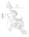
- FIG 4 there is shown an example of the construction of a mechanism for separating the upper unit 1a and the lower unit 1b from each other and opening the interior of the apparatus to thereby secure the space available for the above-mentioned repairs and treatment.
- the reference numeral 11 designates a hinge disposed on the side opposite to the discharge port 9 to permit pivotal movement of the upper unit 1a relative to the lower unit 1b
- the reference numeral 13 denotes a spring for holding the upper unit 1a in its opened position.
- the recording head 101, the rollers 113 and 115, etc. are disposed near the discharge port 9 in the upper unit 1a, and the platen 203, the idlers 213, 215, the paper cassette 221, the ink tank 231 and the ink absorbing member 235 are disposed near the discharge port 9 in the lower unit 1b and therefore, in the opened position of the body unit portion 1 as shown in Figure 4, the ink system including the recording head 101, the ink tank 231 and the ink absorbing member 235 and the paper supplying or conveying system including the paper cassette 221 and the roller members have been widely opened.
- the upper unit 1a and the lower unit 1b become spaced apart from each other along the path along which the recording medium S is fed out from the cassette 221 to the discharge port 9 and thus, design has been made such that the conveyance path is opened if the upper unit 1a is pivoted upwardly relative to the lower unit 1b.
- the construction for thus securing the work space is not limited to that shown in Figure 4, but could be various.
- a good result has been obtained in any of a construction in which suitable struts for supporting the upper unit 1a are provided at four corners of the lower unit 1b and the upper unit 1a is made vertically movable along the struts, a construction in which the upper unit 1a is obliquely upwardly slidable in its horizontal state by the use of a parallel link mechanism, and a construction in which the upper unit 1a and the lower unit 1b are not opened in the vertical direction but are opened in the horizontal direction.
- the hinge type of the present embodiment is simple in construction and reliable in operation and has been very preferable.
- the recording head 101 has been disposed on the upper unit 1a side and the ink tank 231 has been disposed on the lower unit 1b side. Also, they have been designed to communicate with each other through a supply tube 233.
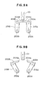
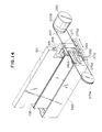
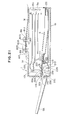
- Figure 5A is a schematic side sectional view showing the connecting state of the supply tube
- Figure 5B is a perspective view thereof.
- pivotable ink joint members 101A and 231A are provided at the connecting portion between the recording head 101 and the ink supply tube 233 and the connecting portion between the ink tank 231 and the ink supply tube 233, respectively, so that the displacement of the body unit portion 1 resulting from the opening or closing thereof may be absorbed by the rotation of the pivotable ink joint members 101A and 231A.
- the reference characters 101B and 231B designate O-rings for shutting off the ink.
- Figure 5B shows the details of the connected portion of the supply tube, and particularly shows the construction thereof on the ink tank 231 side.
- the reference character 231D designates an elbow provided integrally with the supply tube 233 at one end thereof
- the reference character 231C denotes a keep ring for the O-ring 231B
- the reference character 231E designates a keep plate for controlling the elbow 231D vertically relative to the ink tank 231 and holding the elbow 231D so as not to slip off from the ink tank 231.
- the elbow 213D has been made rotatively slidable relative to the ink tank 231, the O-ring 231B, the keep ring 231C and the keep plate 231E.
- the supply tube 233 has been made into a flexible tubular member formed of a material such as polyethylene, whereby the upper unit 1a and the lower unit 1b could be smoothly opened without a great influence being exercised upon the ink flow path.
- the elbow 231D is pivotable relative to the ink tank 231 and the recording head 101 and therefore, when the upper unit 1a and the lower unit 1b have been opened, the angle of mounting of the supply tube 233 has been naturally displaced by the resiliency of the supply tube itself.
- the slack of the supply tube 233 when the upper unit 1a and the lower unit 1b remain closed could be reduced and the amount of deformation of the supply tube could be reduced.
- the supply tube 233 could be made to have a length sufficient to connect the ink tank 231 and the recording head 101 substantially linearly when the units 1a and 1b were opened at a maximum angle of opening (see Figure 4) and therefore, the flexibility required of the supply tube 233 could be designed to a small value.
- the construction permitting the opening of the units 1a and 1b is not limited to the above-described construction comprising a combination of the flexible supply tube and the pivotable joints, but use could be made, for example, of a construction in which a relatively rigid supply tube was connected through bellows or the like.
- the distance of blight of an ink droplet i.e., the distance between the opening portion of the nozzle of the recording head 101 and the paper
- the upper unit 1a having the recording head 101 and the lower head 1b having the platen 203 which controls the paper can be spaced apart from each other, it is desirable to give consideration so that in the joined state of the units, the recording head and the platen are accurately opposed to each other in parallel relationship with each other.
- the on-demand type recording head 101 has been disposed near the discharge port 9 of the apparatus with the discharge ports thereof facing vertically downwardly and the paper cassette 221 has been disposed below the electric circuit portion 103 so that a recording medium conveyance path including the platen 203 is formed below the discharge ports of the recording head and therefore, the conveyance distance of the recording medium has been shortened and the conveying system has been simplified and accordingly, the construction of the apparatus could be made very compact.
- the main electric circuit portion 103 has been provided on the upper unit 1a side in common with the recording head 101 and therefore, even when the ink has been discharged or when leakage of the ink has occurred, the ink has not adversely affected the electric circuit portion 103.
- the internal pressure of the apparatus has been made higher than the atmospheric pressure so that there is formed an air stream flowing out through the discharge port 9, whereby the ink mist produced during the discharge of ink droplets by the head 101 provided near the discharge port 9 and the paper powder or the like produced by the conveyance of the recording medium have been quickly carried out of the apparatus and thus, the contamination or accident which would otherwise result from the adherence of the ink to the various interior parts in the apparatus has been reliably prevented.
- the upper unit 1a has been made pivotable relative to the lower unit 1b by the hinge 11 disposed on the side opposite to the discharge port 9, whereby during the pivotal movement thereof, the ink system and the conveying system have been widely opened and accordingly, the work required for the repairs of various parts and the jam treatment has become easy.
- the compactness of various parts including the conveying system has been achieved by providing the recording head near the discharge port, but the location at which the recording head is disposed is not always limited to the neighborhood of the discharge port.
- an outflow port for air has been provided separately near the recording head so that the ink mist, etc. may be rapidly discharged, whereby the problems of the ink mist, etc. could be solved.
- each base plate 103A is horizontally disposed and therefore, the air stream from the far 150 suffers very little from the loss by resistance and is effectively directed to the vicinity of the recording head 101 and the ink mist, paper powder, etc. are rapidly discharged from the discharge port 9, but the effect of the air stream could be made more reliable by adopting a suitable arrangement.
- it has also been effective to incline each base plate 103A so as to become lower toward the left as viewed in Figures 2 and 3 so that the air stream from the fan 150 directly impinges on the discharge ports of the recording head 101.
- duct 180 having an opening 180A opposed to the fan 150 and an opening 180B opposed to the recording head 101, as shown in Figure 6, so that the air stream is directed to the recording head 101 through the duct 180.
- blower means forming a flow of air might be disposed separately at a suitable location. Also, an effect has been found in driving this blower means only during printing, and by doing so, it has been possible to minimize the desiccation of the nozzles 101a, etc. of the recording head 101.
- blower means used to eliminate the ink mist could be any one which would increase the internal pressure of the apparatus slightly above the atmospheric pressure, and has been sufficiently effective even if the air stream formed thereby is minute.
- the present embodiment has been described with respect to a case where the host apparatus H is employed as the recording data supply source, but of course, such a data supply source may be any one.
- reading means for reading the image of an original may be provided on top of the upper unit 1a and the read image information may be converted into an electrical signal which in turn may be supplied to the recording head 101.
- a preferred embodiment provided with such image reading means will be described later as a second embodiment.
- the reference numeral 203 designates the platen provided on the lower unit 1b side in opposed relationship with the recording head 101 to control the recording surface.
- the platen 203 has been made movable from its position opposed to the recording head 101, by a driving portion to be described which is not shown in Figure 7.
- the recording mediums piled on the aforementioned paper cassette 221 are separated one by one by the paper supply roller 111 through the cooperation thereof with separating means (not shown) and are conveyed toward the recording station.
- Designated by 225 is the bottom plate of the apparatus.
- the bottom plate 225 has been used also as a partition wall for blocking the outflow of leaking ink to the outside of the apparatus when unexpected leakage of ink from the recording head 101, etc. has occurred.
- the reference numeral 233 designates a flexible supply tube for communicating the recording head with an ink tank, not shown, as an ink supply source.
- the reference numeral 235 denotes an ink absorbing member formed of a water-absorbent porous material. In the present embodiment, the ink absorbing member 235 has been disposed below the platen 203.
- the ink absorbing member 235 could be designed so as to be capable of appropriately replacing the platen 203 in position and being opposed or joined to the discharge ports of the recording head 101 so that the ink absorbing member could be used for the restoration of the discharge of the recording head 101 and for the capping of the recording head.
- the reference numeral 150 designates a fan for introducing the air from the outside of the apparatus and thereby cooling various parts of the apparatus.
- this fan 150 has been disposed on that side of the apparatus which is opposite to the discharge port 9 for the recording medium, whereby the air stream from an air intake port 5a in said side to the discharge port 9 has been produced.
- the recording head 101 has been provided near the discharge port 9 and therefore, the satellite which may secondarily occur during the discharge of ink droplets from the recording head 101, the ink mist which may be caused on the surface of the recording medium by the scattering of ink, dust, the paper powder of the recording medium, etc.
- the cooling fan 150 for cooling the electric circuit portion 103, etc. has been used also as blower means in the apparatus which eliminates the ink mist.
- Figure 8 shows an example of the construction of a driving portion for the platen according to the present invention.
- the reference characters 203A and 203B designate platen members forming the platen 203 in the joined state shown.
- the platen members 203A and 203B are connected through arms 251A and 251B to shafts 253A and 253B extending lengthwise of the recording head 101, and are pivotable about these shafts 253A and 253B in a direction to open the recording surface.
- Gears 255A and 255B are provided on the ends of the shafts 253A and 253B, respectively, and through these gears 255A and 255B, the platen members are connected to a set of gears 257A and 257B meshing with each other, so that the directions of pivotal movement of the platen members 203A and 203B for opening/forming the recording surface may be opposite to each other.
- the transmission mechanism including these gears are combined with a motor 260 through a gear 259, and by controlling the direction of revolution of the motor 260, predetermined pivotal movement of the platen members 203A and 203B has been made possible.
- the dashing surface 204A of the platen member 203A and the dashing surface 204B of the platen member 203B are held in their joined state, whereby the platen members 203A and 203B are designed to form the platen 203 for controlling the recording surface of the recording medium by the recording head 101.
- the platen members 203A and 203B are opened to the left and right as viewed in the figure by driving the motor 260, through the transmission mechanism, whereby a space is secured below the recording head 101 and, for example, by joining the ink absorbing member to the discharge ports of the recording head 101, it has become possible to effect cleaning or effect the discharge restoring operation such as preliminary discharge with the ink absorbing member being proximately opposed to the discharge ports of the recording head.
- Such joining or proximate disposition of the ink absorbing member may be accomplished as by inserting the absorbing member from a suitable location on the apparatus, or could be accomplished by bringing the ink absorbing member into proximity to the discharge ports of the recording head by a suitable mechanism through the space secured with movement of the platen members 203A and 203B.
- the platen 203 has been constructed of the two members 203A and 203B so that during recording, the dashing surfaces 204A and 204B are joined together and therefore, when a recording medium has been conveyed, there has occurred a case where the forward movement of the leading end edge of the recording medium is hampered in this dashing portion to cause jam.
- Figures 10A and 10B show two examples of the construction of the platen members 203A and 203B for smoothing the movement of the recording medium and preventing jam as a countermeasure for such jam.
- Figure 10A shows an example in which the both dashing surfaces 204A and 204B are provided with curved surfaces, and by these curved surfaces, the leading end edge of the recording medium has been smoothly guided in the direction of movement indicated by arrow in Figure 10A.
- Figure 10B shows an example in which the dashing surface 204B of the platen member 203B lying at the downstream side in the direction of movement of the recording medium is provided with an inclined surface downwardly inclined with respect to the direction of movement of the recording medium, and occurrence of jam could also be prevented in the dashing portion by such a construction.
- the transmission mechanism comprising the motor 260 and the gear train has been provided to make the two platen members 203A and 203B pivotable, but alternatively, for example, a solenoid might be used during the driving and an appropriate link mechanism might be disposed so that the pivotal movement of the platen members 203A and 203B might be accomplished.
- Figure 11 shows a further example of the construction of the platen driving portion.
- the platen 203 is a unitary member which is movable in the horizontal plane in a direction orthogonal to the lengthwise direction of the recording head 101, i.e., the direction of conveyance of the recording medium.
- the reference characters 270A and 270B designate pulleys over and between which is extended a wire 267 for moving the platen 203 in the direction of arrow.
- the reference numeral 265 denotes a motor coupled to one pulley 270B to move the platen 203 through the wire 267.
- the reference numeral 271 designates a wire fixing bed which is provided on the platen 203 to fix the platen to the wire 267.
- the reference numeral 273 denotes wheels provided on the platen 203 to move the platen 203 smoothly along a guide rail 275 extending in the direction of arrow.
- the reference characters 275A and 275B designate stoppers provided on the guide rail 275 and engageable by the wheels 273 to position the platen 203 at a position opposed to the recording head 101 and a position spaced apart from the recording head 101.
- the platen 203 is positioned at the shown position to control the recording surface of the recording medium, while during maintenance, the motor 265 is driven to position the platen 203 at the position of the stopper 275B, whereby a large work space could be secured below the recording head 101 to improve the working property.
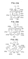
- Figure 12 shows an example of the construction of the platen driving portion according to the present invention.
- the reference characters 203A and 203B designate platen members forming the platen 203 in their joined state shown.
- the platen members 203A and 203B are connected through arms 251A and 251B to shafts 253A and 253B, respectively, extending lengthwise of the recording head 101 and are pivotable about these shafts 253A and 253B in a direction to open the recording surface.
- Gears 255A and 255B are provided on the ends of the shafts 253A and 253B, respectively, and through these gears 255A and 255B, the platen members are connected to a set of gears 257A and 257B meshing with each other so that the directions of pivotal movement of the platen members 203A and 203B for opening/forming the recording surface are opposite to each other.
- the transmission mechanism including these gears is combined with a motor 260 through a gear 259, and by controlling the direction of revolution of this motor 260, predeter-mined pivotal movement of the platen members 203A and 203B has been made possible.
- the lower portions of the arms 251A and 251B have been made to extend inwardly from their mounted portions with respect to the shafts 253A and 253B and those inwardly extending portions have been engaged with the bottom surface of a case 235A in which an ink absorbing member 235 is contained.
- the dashing surface 204A of the platen member 203A and the dashing surface 204B of the platen member 203B are held in their joined state, whereby the platen members 203A and 203B have been designed to form the platen 203 for controlling the recording surface of the recording medium by the recording head 101. Also, design has been made such that at this time, the inwardly extending portions 252 of the respective arms are engaged with the bottom surface of the case 235A in their substantially horizontally kept state and therefore, the ink absorbing member 235 has been positioned below the platen members 203A and 203B.
- the cleaning of the end surface including the discharge ports could be accomplished by pivotally moving the arms 251A and 251B from their state of Figure 13B and joining the ink absorbing member 235 to the discharge ports of the recording head 101, as shown in Figure 13C.
- the ink, etc. adhering to the end surface of the discharge ports have been immediately absorbed by the ink absorbing member 235 and the restoration of discharge by cleaning has been accomplished.
- an elastic member formed of silicone rubber or like material is disposed instead of the ink absorbing member 235, the function of capping which protects the vicinity of the discharge ports from desiccation or entry and adherence of dust or the like during the non-use of the apparatus would be performed.
- the platen 203 has been constructed of the two members 203A and 203B and design has been made such that the dashing surfaces 204A and 204B are joined together during recording and therefore, there have been cases where the movement of the leading end edge of the recording medium is hampered in the dashing portion to cause jam when the recording medium is conveyed.
- the transmission mechanism comprising the motor 260 and the gear train has been provided to enable the two arms 251A and 251B to be pivotally moved, but the same purpose could also be achieved, for example, by using a solenoid during the driving and disposing an appropriate link mechanism to thereby pivotally move the platen members 203A and 203B.
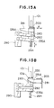
- Figure 14 shows still a further example of the construction of the platen driving portion.
- the platen 203 comprises a unitary member and is made moveble in a horizontal plane in a direction orthogonal to the lengthwise direction of the recording head 101, i.e., the direction of conveyance of the recording medium, and the ink absorbing member 235 is vertically movable with the movement of the platen.
- the reference characters 270A and 270B designate pulleys over and between which is extended a wire 267 for moving the platen 203 in the direction of arrow.
- the reference numeral 265 denotes a motor coupled to one pulley 270B to move the platen 203 through the wire 267.
- the reference numeral 271 designates a wire fixing bed which is provided on the platen 203 to fix the platen to the wire 267.
- the reference numeral 273 denotes wheels combined with the platen 203 to move the platen 203 smoothly along a guide rail 275 extending in the direction of arrow.
- the reference characters 275A and 275B designate stoppers provided on the guide rail 275 and engageable by the wheels 273 to position the platen 203 at a position opposed to the recording head 101 at a position for joining the ink absorbing member 235 to the recording head 101.
- the reference numeral 281 denotes a guide member combined integrally with the platen 203.
- the guide member 281 is provided with a cam surface 281A engageable with a guide pin 283 projectedly provided on a case 235A containing the ink absorbing member 235 therein to thereby permit vertical movement of the ink absorbing member 235.
- the case 235A is normally biased upwardly by a bias member such as a spring (see Figures 15A and 15B), and the upward movement thereof has been controlled by the guide pin 283.
- the reference numeral 290 designates a fixed bed which is fixed to the apparatus, and the reference numeral 292 denotes a parallel link which connects the fixed bed 280 to the case 235A. The falling of the ink absorbing member 235 during the vertical displacement thereof has been prevented thereby.
- the motor 265 is controlled to appropriately position the platen 203 between the stoppers 275A and 275B, the ink absorbing member 235 becomes opposed to the recording head 101 with a proper distance kept therebetween and therefore, the discharge restoring operation by preliminary discharge could be performed.
- FIG. 16 A schematic perspective view of this embodiment is shown in Figure 16.
- the reference numerals given in Figure 16 are similar in significance to those given in Figure 2 and therefore need not be described in detail.
- the platen 203 is made movable from its position opposed to the recording head 101 by a driving portion, not shown. That is, as will be described later, in the present embodiment, the ink absorbing member 235 is designed so as to be capable of appropriately replacing the platen 203 in position in response to movement of the platen and being opposed or joined to the discharge ports of the recording head 101 for use in the discharge restoring operation of the recording head 101. Thereby the ink from the recording head 101 has been appropriately collected during recording.
- the ink absorbing 235 is disposed below the platen 203 integrally with the ink tank 231.
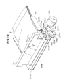
- Figure 17 shows an example of the construction of the essential portions of the present invention.
- the reference numeral 234 designates a cartridge containing therein the ink tank 231 and the ink absorbing member 235 as a unit
- the reference character 234A denotes a joint for connecting the ink tank 231 to the supply tube 233.
- the reference characters 203A and 203B designate platen members adapted to form the platen 203 in their joined state (the state in which they cover the upper surface of the ink absorbing member 235).
- the platen members 203A and 203B are connected, for example, integrally to the cartridge 234 through a link 241 and are made pivotable about pivots on the cartridge 234 in a direction to uncover the upper surface of the ink absorbing member 235 and a direction to cover the upper surface of the ink absorbing member 235.
- the link 241 and the cartridge 234 might be connected together by a tension spring so that when no extraneous force is applied, the platen members 203A and 203B might be pivotally moved in the direction to cover the upper surface of the ink absorbing member 235.
- These platen members may function as a protective member for protecting the ink absorbing member.
- the pivots of the platen members 203A and 203B by the link 245 might be appropriately determined so that the platen members 203A and 203B might normally cover the upper surface of the ink absorbing member 235, or there has been no problem even when a spring has been combined therewith.
- the cartridge 234 on which the platen members 203A and 203B are mounted has been made movable in the vertical direction of arrow B by a suitable driving member.
- the link 241 has been provided with an opening-closing shaft 241A which comes into engagement with a member fixed to the apparatus with the upward displacement of the cartridge 234 by the driving member 248 and opens the platen members 203A and 203B with said engagement.
- the cartridge 234 has been made removably mountable with respect to the apparatus so that the ink tank 231 and the ink absorbing member 235 can be interchanged as a unit.
- the direction in which the ink cartridge 234 is taken out could be, for example, the lengthwise direction thereof as indicated by arrow A.
- the platen members 203A and 203B are engaged with the cartridge 234 through the link 241.
- the reference numeral 245 designates a fixed wall which is fixed to the apparatus and serves as an engagement member engageable with the opening-closing shaft.
- the reference numeral 248 denotes a cam as a driving member having an arm portion 248B engaged with the bottom surface of the cartridge 234 and pivotable about a pivot 248A fixed to the apparatus.
- the other arm portion 248C of the cam 248A has been coupled to drive means such as a motor or a solenoid through a suitable transmission mechanism so that during the discharge restoring operation, the drive means may be driven to thereby move the cartridge 234 upwardly.
- the absorbing capacity of the ink absorbing member 235 (the amount of ink which can be absorbed by the ink absorbing member) is set to a value greater than the initial amount of ink in the ink tank 231, it has been possible without any special means for detecting the amount of ink in the ink absorbing member being provided to prevent the inconvenience that the ink which could not completely absorbed by the ink absorbing member 235 leaks therefrom to contaminate various parts in the apparatus or the cartridge 234 is interchanged with unused ink left therein.
- this is also applicable to the ink absorbing member shown in the aforedescribed embodiment.
- the platen members 203A and 203B have provided a lid member for covering the ink absorbing member 235 and thus, the ink has not contaminated the operator's hand or the like during the interchange of the cartridge.
- the platen 203 has been constructed of the two members 203A and 203B and design has been made such that these platen members are dashed against each other and joined together during recording and therefore, when the recording medium has been conveyed, there have been cases where the movement of the leading end edge of the recording medium is hampered in the dashing portion to cause jam.
- such problem could be solved by the application of the construction shown in Figures 10A and 10B.
- the recording head 101 is disposed on the upper unit 1a side and the ink tank 231 is disposed on the lower unit 1b side and they are communicated with each other through the supply tube 233 and therefore, it has been preferable that as previously described, a pivotable ink joint member be provided, for example, in at least one of the connecting portion between the recording head 101 and the ink supply tube 233 and the connecting portion between the ink tank 231 and the ink supply tube 233 so that the displacement resulting from the vertical movement of the cartridge 234 may be absorbed by the pivotable ink joint.
- a supply tube comprising two relative rigid tube members coupled together through retractile bellows.
- Embodiment 1 has been described with respect to a case where the present invention is applied to an ink jet recording apparatus having an on-demand type recording head using a discharge energy generating member represented by an electro-thermal converting element and having discharge ports disposed downwardly, the present invention is of course effectively and readily applicable also to recording apparatuses adopting various drive systems and arrangements.
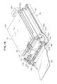
- Figure 19 is a perspective view showing an example of the outer construction of a recording apparatus provided with image reading means
- Figure 20 is a perspective view showing the recording apparatus with its outer cover removed for convenience.
- the reference numeral 1 designates a body unit portion having an upper unit 1a as a first unit and a lower unit 1b as a second unit.
- the upper unit 1a has been made pivotable up and down about a hinge 11 relative to the lower unit 1b.
- the upper unit 1a is provided with a recording head 101, an electric circuit portion 103, a fan 150, an upper discharge roller 115a, an upper conveyor roller 113a, a paper guide 201 and a paper supply roller 111 which will be described later.
- the lower unit 1b is provided with a platen 203, an ink absorbing member 235, an ink tank 231, a paper cassette 221, a paper discharge tray 9A and idlers 213, 215.
- the reference numeral 5 denotes a cover disposed over the body unit portion 1.
- the cover 5 has an operating portion 7 in which are disposed various command switches 7a and 7b such as on-line switches and a display device 7c for effecting the mode display, and in addition, an insertion port 8A for a medium (an original) bearing image information to be read, and a discharge port 8B for the read original, and is provided with an original reading apparatus containing portion 8 which covers a reading apparatus to be described with reference to Figure 20.
- the reference numeral 9 designates a discharge port provided in one side of the apparatus. Recording mediums S on which recording has been effected may be piled on the discharge tray 9A through the discharge port 9.
- Figure 20 is a perspective view showing a state in which the cover 5 of the apparatus shown in Figure 19 has been removed to illustrate the interior construction of the Figure 19 apparatus, and Figure 21 shows a side cross-section of the apparatus shown in Figure 19.
- the reference numeral 101 designates an image processing head disposed near the discharge port 9.
- the image processing head 101 is in the form of the so-called full multi-type wherein nozzles 101a are arranged, for example, at a density of 16 nozzles per 1 mm, over a range corresponding to the full recording width (e.g. recording paper of format A4) of the present apparatus.
- discharge energy generating members represented by electro-mechanical converting elements (not shown) or electro-thermal converting elements (not shown) are disposed at appropriate locations in the ink flow paths such as the nozzles and discharge energy has been caused to act on ink in response to the supply of a driving signal corresponding to an image to be recorded (i.e., a driving signal corresponding to the reading signal of an original reading apparatus 800), whereby ink has been discharged from the discharge ports 101b.
- the recording head 101 is provided in such a manner that the discharge port 101b of each nozzle 101a opens vertically downwardly.
- the reference numeral 103 denotes the main electric circuit portion of the present apparatus in which a driver circuit for driving the recording head 101 though a flexible cable 102, a driver circuit for the original reading apparatus 800, a signal processing circuit, a power source circuit, a control circuit, an interface circuit with the various circuits in the apparatus, etc. are provided on a base plate 103A.
- the main electric circuit portion 103 is provided in the upper unit 1a in common with the recording head 101 and therefore, even if the ink discharge during recording or unexpected leakage of ink has occurred, the ink has not exerted any influence upon the electric circuit portion 103.
- the electric circuit portion 103 is disposed at a level higher than the positions at which the discharge ports 101b of the recording head 101 are disposed. Thus, it has become more difficult for the ink to exert an influence upon the electric circuit portion 103.
- the above-described arrangement of the electric circuit portion 103 and the discharge ports 101b has been a preferable arrangement, but has not always been necessary.
- the reference numeral 111 designates a paper supply roller formed by cutting away a part of an arc.
- the paper supply roller 111 is a roller for supplying recording mediums S such as paper, films or cloths from a cassette 221 containing the recording mediums S therein toward the recording station in which recording is effected by the recording head 101.
- the reference numerals 113 and 115 respectively denote a conveyor roller disposed at the upstream side on a recording medium conveyance path P with respect to the recording station and a discharge roller disposed near the discharge port 9 at the downstream side. These rollers 113 and 115 are adapted to be rotatively driven by a motor 117 through a timing belt 119. Thus, in response to this rotative drive, the conveyor roller 113 and the discharge roller 115 have cooperated with idlers 213 and 215 disposed in opposed relationship therewith to effect the conveyance of the recording medium S to the recording station with the recording medium S head therebetween or the discharge of the recording medium S from the recording station to the discharge tray 9A.
- the reference numeral 201 designates a paper guide provided on the conveyance path P of the recording mediums S to restrict the conveyance path P
- the reference numeral 203 denotes a platen provided on the lower unit 1b side in opposed relationship with the discharge ports 101b of the recording head 101 to maintain the recording medium S in the recording station, that is, control the recording surface, when recording is effected on the recording medium S by the recording head 101.
- the recording mediums S piled in the aforementioned paper cassette 221 are separated one by one by the paper supply roller 111 through the cooperation thereof with separating means (not shown) and conveyed toward the recording station.
- the reference numeral 225 designates the bottom plate of the apparatus. In the present embodiment, this bottom plate 225 has served also as a partition wall for blocking the outflow of leaking ink to the outside of the apparatus when unexpected leakage of ink from the recording head 101, etc. has occurred.
- the reference numeral 231 denotes an ink tank as an ink supply source to the recording head 101.
- the ink tank 231 is disposed below the platen 203 and designed to supply ink to the recording head 101 through a flexible supply tube 233.
- the reference numeral 235 designates an ink absorbing member formed of a water-absorbent porous material.
- the ink absorbing member 235 is disposed on top of the ink tank 231 below the platen 203.
- this ink absorbing member 235 might appropriately replace the platen 203 in position and be constructed so as to be capable of opposing or bearing against the discharge ports 101b of the recording head 101 and to be used for the discharge restoring operation or the capping operation of the recording head 101. Thereby, the ink dripping from the recording head 101 could be appropriately collected.
- the reference numeral 150 designates a fan for introducing the air from the outside of the apparatus to thereby cool the various portions of the apparatus.
- this fan 150 has been disposed on that side of the apparatus which is opposite to the discharge port 9, whereby the air stream (indicated by arrows a in Figure 20) from an air intake port 5a in said side to the discharge port 9 has been produced.
- the recording head 101 has been provided near the discharge port 9 and therefore, the satellite which may secondarily occur during the discharge of ink droplets from the recording head 101, the ink mist which may be caused on the surface of the recording medium S by the scattering of ink, dust, the paper powder of the recording medium, etc.
- the cooling fan 150 for cooling the electric circuit has been used also as blower means in the apparatus which eliminates the ink mist.
- the reference numeral 800 denotes an original reading apparatus disposed above the electric circuit portion 103.
- the original reading apparatus 800 has a sensor unit 801 for reading image information (for example, a contact sensor unit as shown), an original feeding roller 813 for feeding an original M inserted into the insertion port 8A toward the sensor unit 801, and an original discharging roller 815 for discharging the read original M from the discharge port 8B.
- a sensor unit 801 for reading image information for example, a contact sensor unit as shown
- an original feeding roller 813 for feeding an original M inserted into the insertion port 8A toward the sensor unit 801
- an original discharging roller 815 for discharging the read original M from the discharge port 8B.
- the sensor unit 801 is provided with an illuminating device 803 for illuminating the position at which the original conveyed between the rollers 813 and 815 is read, and a line sensor 805 in which light-receiving elements are arranged so that one-line reading can be accomplished over the full width of the original.
- the image information read thereby has been directed to a suitable processing circuit provided in the electric circuit portion 103, and the recording head 101 has been driven for the thus processed image information whereby image formation could be accomplished.
- the rollers 813 and 815 in the original reading apparatus are coupled to and driven by the motor 117 through a transmission mechanism including a timing belt 819 and a gear 821 and are designed to cooperate with idlers 823 and 825 disposed in opposed relationship with the respective rollers to convey the original.
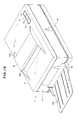
- the body unit portion 1 is made separable into the upper unit 1a and the lower unit 1b as will be described below to facilitate repairs of various parts and jam treatment.
- Figure 22 shows an example of the construction of a mechanism for separating the upper unit 1a and the lower unit 1b from each other and opening the interior of the apparatus to thereby secure a space available for said works.
- the reference numeral 11 designates a hinge disposed on the side opposite to the discharge port 9 to permit pivotal movement of the upper unit 1a relative to the lower unit 1b
- the reference numeral 13 denotes a spring for holding the upper unit 1a in its opened position.
- the recording head 101, the rollers 113 and 115, etc. are disposed near the discharge port 9 in the upper unit 1a, and the platen 203, the idlers 213, 215, the paper cassette 221, the ink tank 231 and the ink absorbing member 235 are disposed near the discharge port 9 in the lower unit 1b and thus, design is made such that in the opened state of the body unit portion 1 as shown in Figure 22, the ink system including the recording head 101, the ink tank 231 and the ink absorbing member 235 and the paper supplying or conveying system including the paper cassette 221 and the various roller members are widely opened.
- the upper unit 1a and the lower unit 1b become spaced apart from each other along a path along which the recording medium S is fed out from the cassette 221 to the discharge port 9 and therefore, when the upper unit 1a has been pivoted upwardly relative to the lower unit 1b, the conveyance path has been opened.
- the construction for thus securing the work space is not limited to that shown in Figure 22, but could be various.
- suitable struts for supporting the upper unit 1a might be provided at four corners of the lower unit 1b and the upper unit 1a might be made vertically movable along those struts, or the upper unit 1a might be slidden obliquely upwardly in its horizontal state by the use of a parallel link mechanism, or the direction in which the upper unit 1a and the lower unit 1b are opened is not limited to the vertical direction, but for example, the upper unit and the lower unit might be opened in the horizontal direction.
- the recording head 101 has been disposed on the upper unit 1a side and the ink tank 231 has been disposed on the lower unit 1b side, and they have been designed to communicate with each other through a supply tube 233.
- the supply tube 233 could be connected by the use of the connecting method as described in Embodiment 1 with reference to Figures 5A and 5B.
- the distance of flight of ink droplet i.e., the distance between the nozzle opening portion of the recording head 101 and the paper
- the upper unit 1a having the recording head 101 and the lower unit 1b having the platen 203 for controlling the paper can be spaced apart from each other and therefore, it is desirable to give consideration so that in the joined state of the units, the recording head and the platen are accurately opposed to each other in parallel relationship with each other.
- the original reading means has been disposed integrally with the recording means at an appropriate location, i.e., above the electric circuit portion, whereby a system construction of compact size and high operability has become possible.
- the on-demand type recording head 101 has been disposed near the discharge port 9 of the apparatus with the discharge ports thereof facing vertically downwardly and the paper cassette 221 has been disposed below the electric circuit portion 103 so that a recording medium conveyance path including the platen 203 is formed below the discharge ports of the recording head and therefore the conveyance distance of the recording medium has been shortened and the conveying system has been simplified and accordingly, the construction of the apparatus could be made very compact.
- the original reading apparatus and the main electric circuit portion 103 have been provided on the upper unit 1a side in common with the recording head 101 and therefore, even when the ink has been discharged or when leakage of the ink has occurred, the ink has not adversely affected the original reading apparatus 800 and the electric circuit portion 103.
- the internal pressure of the apparatus has been made higher than the atmospheric pressure so that there is formed an air stream flowing out through the discharge port 9, whereby the ink mist produced during the discharge of ink droplets by the head 101 provided near the discharge port 9 and the paper powder or the like produced by the conveyance of the recording medium have been quickly carried our of the apparatus and thus, the contamination or accident which would otherwise result from the adherence of the ink to the various parts in the apparatus including the original reading apparatus 800 has been reliably prevented.
- the upper unit 1a has been made pivotable relative to the lower unit 1b by the hinge 11 disposed of the side opposite to the discharge port 9, whereby during the pivotal movement thereof, the ink system and the conveying system have been widely opened and accordingly, the work required for the repairs of various parts and the jam treatment has become easy.
- Embodiment 1 has been described with respect to a case where the present invention is applied to a recording apparatus having an on-demand type and full multi-type recording head using an electro-mechanical converting element or an electro-thermal converting element as a discharge energy generating member, the present invention is of course applicable also to recording apparatuses adopting various drive systems and scanning systems.
- the construction of the original reading apparatus 800 is neither restricted to the above-described example, but for example, even a construction using an optical system can be commonly used as viewed in terms of manufacturing cost or the like although it is partly contradictory in respect of further compactness.
- a host apparatus as an image information supply source.
- the ink supply tube is made displaceable, the opening of the first and second units can be allowed without involving the separation of the ink supplying system and for example, as in the above-described embodiment, an appropriate construction becomes possible in which the ink tank and the recording unit are disposed in the lower unit and the upper unit, respectively.
- an ink jet recording apparatus in which various parts of the apparatus including an electric circuit can be reliably protected from ink mist or the like can be realized by the present invention.
- the present invention can provide an apparatus which is not only compact but also high in reliability because there is no movement or displacement of ink supply means and signal transmitting members associated with the recording head, as compared with an apparatus designed such that the recording head is moved relative to the platen to thereby secure the work space.
- the platen and the restoring member are operatively associated with each other and the access thereof to the recording head is made possible by appropriately substituting the position thereof and therefore, a simple and reliable discharge restoring operation becomes possible without involving great displacement thereof.
- the platen and the restoring member are operatively associated with each other so that the access thereof to the recording head can be accomplished by appropriately substituting the position thereof and therefore, simple and reliable discharge restoration becomes possible without requiring great displacement thereof, and the restoring member and the ink tank are made unitary and therefore, the interchanging work becomes simple and saving of the space can be achieved.
- the platen also is made unitary as in the above-described embodiment, the platen serves as a lid member for the restoring member and therefore, the undesirable possibility of the operator's hand or the like being contaminated during interchange is eliminated.
- the reading means is made integral with the recording means and an ink jet recording apparatus is used as the recording means and therefore, it is possible to make the most of the advantage thereof, and an image processing apparatus which is compact and high in operability can be realized. Also, the separability and openability of the two units can improve the operability of maintenance and jam treatment.
- the ink supply tube is made displaceable and therefore, the separation and opening of the units can be allowed without involving the separation of the ink supplying system and for example, as in the above-described embodiment, it becomes possible to provide an appropriate construction in which the ink tank is disposed in the lower portion and the recording head and the reading apparatus are disposed in the upper portion.
- a recording apparatus is provided with an upper unit having recording head for discharging ink for effecting recording on a recording medium in response to information, and at least a portion of the electric circuit of the apparatus, a lower unit having a platen for maintaining the recording medium in the recording station by the recording head, the lower unit being capable of being spaced apart relative to the upper unit, and conveying member for conveying the recording medium to the recording station.
- the upper unit and the lower unit are capable of being spaced apart and opened in the recording station by the recording head.
Abstract
Description
- This invention relates to a recording apparatus and an ink cartridge in use for the apparatus, and more particularly to a recording apparatus having an ink jet recording head using ink to effect recording (an ink jet recording apparatus).
- As recording means used in a recording apparatus, the ink jet recording system has numerous advantages such as very small noise during recording and capability of effecting recording on plain paper, and has been attracting more and more attention in recent years.
- Also, a recording apparatus which reads image information from a medium (an original) bearing information and effects a series of image processing operations in which the image information is recorded on a recording medium such as paper is now an apparatus indispensable in the information processing system. Such a recording apparatus also has numerous advantages such as very small noise during recording and capability of effecting recording on plain paper and therefore, the ink jet recording systems have been attracting more and more attention.
- Above all, the ink jet recording system called the on-demand type which effects ink discharge during recording by the utilization of either a piezoelectric element or a magnetostrictive element which is an electro-mechanical converting element or an electro-thermal converting element has a great advantage that it does not require means for collecting unnecessary ink and a high voltage source for deflection, because it consumes ink only when necessary for recording.
- Now, with the recent spread of so-called OA instruments, the requirement for the compactness and higher recording speed of recording apparatuses as image forming apparatuses has been rising and therefore, also in recording apparatuses using the on-demand type ink jet recording system having various advantages, it has been strongly desired to introduce improvements to meet such a requirement.
- On the other hand, the ink jet recording apparatus, which generally uses liquid as a recording agent, may experience the clogging or the like of ink in recording means such as a head and thus, improved operability of maintenance of the recording means is desired. Also, recording mediums such as paper may jam in the conveyance path and thus, improved operability of so-called jam treatment is desired.
- Although the ink jet recording apparatus thus has various advantages, dust or paper powder of recording paper has adhered to the discharge ports of the recording head to cause clogging of such ports or cause mixing of bubbles with the interior of the discharge ports, or in the on-demand type ink jet recording apparatus, the frequency of use of a number of nozzles arranged in the recording head is not uniform and therefore, irregularity of discharge conditions has sometimes been caused by an increase in the viscosity of ink. Also, ink has sometimes adhered to a recording medium when it has remained on the end surface of the recording head in which discharge ports open.
- Therefore, in the ink jet recording apparatus, it is requisite to effect a suitable operation for eliminating these various factors which degrade the quality of recording (hereinafter referred to as the discharge restoring operation).
- However, in an ink jet recording apparatus, particularly an ink jet recording apparatus having a so-called full multi-type recording head in which discharge ports are arranged in a range corresponding to the width of the recording medium, a platen for controlling the recording surface is provided in proximately opposed relationship with the discharge ports over the full range in which the discharge ports are arranged and therefore, it has been difficult to secure a large work space when effecting said discharge restoring operation, without making the apparatus bulky.
- That is, in the discharge restoring operation as described above, it is generally practised as an example to effect discharge with a restoring member joined or proximately opposed to the discharge ports.
- However, as mentioned above, in the ink jet recording apparatus having a full multi-type recording head, the platen for controlling the recording surface is provided in proximately opposed relationship with the discharge ports over the full range in which the discharge ports are arranged, and this gives rise to the necessity of replacing the platen with the restoring member when effecting said discharge restoring operation.
- So, an apparatus in which when effecting the discharge restoring operation, the platen is greatly spaced apart from the recording head and in this state, the restoring member can be opposed to the recording head (for example, an apparatus disclosed in our Japanese Patent Application No. 65103/1985 (US Patent Application Serial No. 844,132)) has been proposed, but to contribute to further compactness of the recording apparatus, it is desirable to make the range of movement of the platen or the restoring member small.
- Now, the restoring member receives ink during the discharge restoring operation, etc. and therefore, it is desirable to provide it with an ink absorbing member formed of a water-absorbent porous material. However, such an ink absorbing member is limited in its ink absorbing capacity (the amount of ink absorbed) and therefore, it is preferable to interchange it at suitable chances.
- On the other hand, another member required to be interchanged in the ink jet recording apparatus is an ink tank for ink supply if the ink tank is of the interchangeable type. In the ink jet recording apparatus, when the interchange of both of the restoring member and the ink tank becomes necessary, two stages of discrete operations must be performed during the use.
- In view of the above-noted problems, it is an object of the present invention to provide a recording apparatus which is compact and moreover improved in the operability of maintenance of recording means and the operability of jam treatment.
- It is also an object of the present invention to provide a recording apparatus which is compact and moreover appropriately designed such that various parts including an electric circuit are reliably protected from ink mist, etc.
- It is also an object of the present invention to provide a recording apparatus of such a construction in which during the discharge restoring operation, the displacement of a platen is minimized and moreover a large work space can be secured.
- It is a further object of the present invention to provide a recording apparatus in which a simple and reliable discharge restoring operation can be performed without requiring great displacement of a platen and a restoring member.
- It is also an object of the present invention to provide a recording apparatus in which a simple and reliable discharge restoring operation can be performed without requiring great displacement of a platen and a restoring member and the interchanging work is made simple.
- In addition, it is an object of the present invention to provide a recording apparatus in which recording means and reading means are made integral with each other and the ink jet recording system is used for the recording means to make the most of the advantages thereof and which is compact and high in operability and moreover improved in the operability of maintenance of the recording means and the operability of jam treatment.
- It is an object of the present invention to provide a recording apparatus being characterized by the provision of an upper unit having recording means having ink discharge ports for discharging ink for effecting recording on the recording medium in response to information, and at least a portion of the electric circuit means of the apparatus, a lower unit having a platen for maintaining the recording medium in the recording station by the recording means, said lower unit being capable of being spaced apart relative to said upper unit, and conveying means for conveying said recording medium to said recording station, said upper unit and said lower unit being capable of being spaced apart and opened in the recording station by said recording means.
- It is an object of the present invention to provide a recording apparatus being provided with a first unit having recording means for discharging ink for effecting recording on the recording medium in response to information, a second unit having a platen for maintaining said recording medium in the recording station by said recording means, and ink storing means storing therein the ink to be supplied to said recording means, said second unit being capable of being spaced apart relative to said first unit, conveying means for conveying said recording medium to said recording station, and an ink supply connecting member displaceable in response to the spacing apart of said first unit and said second unit and connecting said recording means to said ink storing means to supply the ink from said ink storing means to said recording means, said first unit and said second unit being capable of being spaced apart and opened in the recording station by said recording means.
- It is an object of the present invention to provide a recording apparatus having a recording head for discharging ink, blower means for introducing the air into the apparatus, and an opening for directing the introduced air to the outside of the apparatus, said opening being provided adjacent to said recording head.
- It is an object of the present invention to provide a recording apparatus having a fan for said blower means to introduce the air, and a member for directing the introduced air to said recording head, said opening being provided adjacent to said recording head and above a containing member containing therein various parts of the apparatus including said recording head.
- It is an object of the present invention to provide a recording apparatus provided with a recording head in which ink discharge ports are arranged, a platen provided in opposed relationship with the discharge ports of said recording head during recording, a cartridge removably provided in the body of the apparatus and integrally holding storing means storing therein ink to be supplied to said recording head a receiving member for receiving the ink from said discharge ports in a state joined or proximate to said discharge ports, and supporting said platen so as to be capable of leaving a position opposed to said discharge ports, and drive means for driving said cartridge to cause said platen to leave said opposed position and cause said receiving member to be joined or proximate to said discharge ports.
- It is also an object of the present invention to provide a recording apparatus provided with a recording head in which ink discharge ports are arranged, a cartridge removably provided in the body of the apparatus and integrally holding a platen opposed to the discharge ports of said recording head during recording, storing means storing therein ink to be supplied to said recording head, and a receiving member for receiving the ink from said discharge ports in a state joined or proximate to said discharge ports, and supporting said platen so as to be capable of leaving a position opposed to said discharge ports, and drive means for driving said cartridge to cause said platen to leave said opposed position and cause said receiving member to be joined or proximate to said discharge ports.
- It is an object of the present invention to provide a recording apparatus provided with a recording head in which ink discharge ports are arranged, a platen provided in opposed relationship with the discharge ports of said recording head, holding means for holding said platen so as to be capable of leaving a position opposed to said discharge ports, and drive means for driving said holding means to cause said platen to leave said opposed position.
- It is an object of the present invention to provide a recording apparatus provided with a recording head in which ink discharge ports are arranged, a platen provided in opposed relationship with the discharge ports of said recording head, an opposing member capable of being opposed to said discharge ports, and holding means for holding said platen so as to be capable of leaving a position opposed to said discharge ports and causing said opposing member to be opposed to said discharge ports in association with said leaving.
- It is also an object of the present invention to provide a cartridge having a receiving member capable of receiving ink, and a movable platen member capable of providing a platen when mounted on the apparatus, and covering said receiving member.
- It is also an object of the present invention to provide an ink cartridge provided with ink tank storing ink therein, a receiving member for receiving the ink, and a movable protective member covering said receiving member.
- It is also an object of the present invention to provide a recording apparatus characterized by the provision of an upper unit having recording means having discharge ports for discharging ink for effecting recording on a recording medium in response to information, reading means for reading image information from a medium bearing an image, and at least a portion of the electric circuit means of the apparatus, a lower unit having a platen for maintaining the recording medium in the recording station by said recording means, said lower unit being capable of being spaced apart relative to said upper unit, and conveying means for conveying the recording medium to the recording station, said upper unit and said lower unit being capable of being spaced apart and opened in the recording station by said recording means.
- It is also an object of the present invention to provide a recording apparatus characterized by the provision of a first unit having recording means having ink discharge ports for discharging ink for effecting recording on a recording medium in response to information, and reading means for reading image information from a medium bearing an image, a second unit having a platen for maintaining the recording medium in the recording station by said recording means, and ink storing means storing therein ink to be supplied to said recording means, said second unit being capable of being spaced apart relative to said first unit, conveying means for conveying the recording medium to the recording station, and an ink supply connecting member displaceable in response to the spacing apart of said first unit and second unit and connecting said recording means to said ink storing means to supply the ink from said ink storing means to said recording means, said first unit and said second unit being capable of being spaced apart and opened in the recording station by said recording means.
- According to the present invention which achieves the above objects, the upper unit and the lower unit are capable of being spaced apart and opened in the recording station, whereby the space available to effect the maintenance of the recording means can be made large and the conveyance path can be opened.
- Also, according to the present invention, the first unit and the second unit are capable of being spaced apart and opened in the recording station, whereby the space available to effect the maintenance of the recording means can be made large and the conveyance path can be opened.
- Also, since the ink supply connecting member is displaceable, the spacing apart of the first and second units is permitted, for example, without involving the separation of the ink supplying system.
- Also, according to the present invention, even when ink mist or the like is caused during ink discharge, it is quickly carried out of the apparatus through an opening and thus, the ink mist or the like does not adversely affect various parts of the apparatus.
- Or, according to the present invention, if a driving member is suitably driven in the discharge restoring operation, the platen will leave the position opposed to the recording head and therefore, a work space will be secured near the recording head.
- Also, according to the present invention, the platen and the joining member are operatively associated with each other and replace each other in position to become opposed to the discharge ports, so that where for example, the joining member is a restoring member, a reliable discharge restoring operation becomes possible without involving great displacement of the platen and joining member.
- Also, according to the present invention, the platen and the receiving member are operatively associated with each other and replace each other in position to become opposed to the discharge ports and therefore, without involving their great displacement, the discharge restoring operation of the recording head becomes possible. Also, since the storing means and the receiving member are provided as a unit in the holding member, the interchanging work is simplified and saving of the space can be achieved.
- Further, according to the present invention, the platen can be used also as a lid member for covering the receiving member when the cartridge is removed from the apparatus body.
- In addition, according to the present invention, the ink jet recording means and the image input means are constructed integrally with each other, whereby there can be provided a recording apparatus which is compact and high in operability while making the most of the advantages of the ink jet recording means. Also, the respective units are capable of being spaced apart and opened in the recording station, whereby the space available to effect the maintenance of the recording means can be made large and the conveyance path can be opened. Further, according to the present invention, the ink supply connecting member is displaceable and thus, the spacing apart of the units is permitted, for example, without involving the separation of the ink supplying system.
-
- Figure 1 is a perspective view showing an embodiment (Embodiment 1) of a recording apparatus to which the present invention is applicable.
- Figure 2 is a perspective view showing the apparatus according to Embodiment 1 of the present invention with the cover portion thereof removed.
- Figure 3 is a side sectional view of the apparatus according to Embodiment 1.
- Figure 4 is a side sectional view showing the apparatus according to Embodiment 1 with the body unit portion and the paper supply portion thereof separated from each other.
- Figures 5A and 5B respectively are an illustration showing an example of the construction of the connecting portion between a recording head and a supply tube in Embodiment 1 and between an ink tank and the supply tube and a perspective view showing the essential portions thereof.
- Figure 6 is a perspective view showing another embodiment of the present invention.
- Figure 7 is a perspective view showing the apparatus according to said another embodiment of the present invention with the cover portion thereof removed.
- Figure 8 is a perspective view showing an example of the construction of the essential portions of the present invention.
- Figures 9A and 9B are side views for illustrating the operation of the embodiment shown in Figure 8.
- Figures 10A and 10B are side views showing two examples of the construction of a platen which can be adopted in the embodiment shown in Figure 8.
- Figure 11 is a perspective view showing another example of the construction of the essential portions of the present invention.
- Figure 12 is a perspective view showing still another example of the construction of the essential portions of the present invention.
- Figures 13A-13C are side views for illustrating the operation of the embodiment shown in Figure 12.
- Figure 14 is a perspective view showing yet still another example of the construction of the essential portions of the present invention.
- Figures 15A and 15B are side views for illustrating the operation of the construction shown in Figure 14.
- Figure 16 is a perspective view showing an apparatus according to another embodiment of the present invention with the cover portion thereof removed.
- Figure 17 is a perspective view showing another example of the construction of the essential portions of the present invention.
- Figures 18A and 18B are side views for illustrating the operation of the embodiment shown in Figure 17.
- Figure 19 is a perspective view showing an embodiment (Embodiment 2) of a recording apparatus provided with image reading means to which the present invention is applicable.
- Figure 20 is a perspective view showing the apparatus according to Embodiment 2 with the cover portion thereof removed.
- Figure 21 is a side sectional view of the apparatus according to Embodiment 2.
- Figure 22 is a side sectional view showing the apparatus according to Embodiment 2 with the body unit portion and the paper supply portion thereof separated from each other.
- Figures 23A and 23B respectively are an illustration showing an example of the construction of the connecting portion between a recording head and a supply tube in Embodiment 2 and between an ink tank and the supply tube and a perspective view showing the essential portions thereof.
- The invention will hereinafter be described in detail with reference to the drawings.
- Figure 1 is a perspective view showing an example of the outer construction of an ink jet recording apparatus which is a preferred embodiment of the present invention, and Figure 2 is a perspective view showing the ink jet recording apparatus with its outer cover removed for convenience.
- In Figures 1 and 2, the reference numeral 1 designates a body unit portion having an upper unit 1a as a first unit and a lower unit 1b as a second unit. The upper unit 1a is pivotable up and down relative to the lower unit 1b about a hinge 11, as shown, for example, in Figure 4. Of course, the upper unit 1a need not always be made pivotable about the hinge 11. The upper unit 1a is provided with a
recording head 101, anelectric circuit portion 103, afan 150, an upper discharge roller 115a, an upper conveyor roller 113a, apaper guide 201 and apaper supply roller 111 which will be described in detail. On the other hand, the lower unit 1b is provided with aplaten 203, anink absorbing member 235, anink tank 231, apaper cassette 221, apaper discharge tray 9A andidlers reference numeral 5 denotes a cover disposed over the upper side of the body unit portion 1. Thecover 5 is provided with an operatingportion 7 in which there are disposedvarious command switches reference numeral 9 designates a discharge port formed in one side of the apparatus. Recording mediums S on which recording has been effected are piled on thedischarge tray 9A through thedischarge port 9. - Figure 2 is a perspective view showing the apparatus of Figure 1 with the
cover 5 removed to illustrate the interior construction of the apparatus of Figure 1, and Figure 3 is a side cross-sectional view of the apparatus of Figure 1. In these figures, thereference numeral 101 designates an ink jet recording head disposed near thedischarge port 9. The inkjet recording head 101 is in the form of the so-called full multi-type whereinnozzles 101a are arranged, for example, at a density of 16 nozzles per 1 mm, over a range corresponding to the full recording width (e.g., recording paper of format A4) of the present apparatus. Also, use may be made of any of methods in which electro-mechanical converting elements (not shown) or electro-thermal converting elements (not shown) are disposed at appropriate locations in the ink flow paths such as the nozzles and discharge energy is caused to act on ink in response to the supply of a driving signal from the host apparatus H corresponding to an image to be recorded, whereby ink is discharged from the discharge ports 101b, but the latter type which uses heat energy is excellent in that it is the high-accuracy full multi-type. In the present embodiment, therecording head 101 is provided in such a manner that the discharge port 101b of eachnozzle 101a opens vertically downwardly. - The
reference numeral 103 denotes the main electric circuit portion of the present apparatus in which a driver circuit for driving therecording head 101 through aflexible cable 102, a power source circuit, a control circuit, various internal circuits of the apparatus and an interface circuit with the host apparatus H outside the apparatus are provided on abase plate 103A. In the present embodiment, the mainelectric circuit portion 103 is provided in the upper unit 1a in common with therecording head 101 and therefore, even if the ink discharge during recording or unexpected leakage of ink has occurred, the ink has not exerted any influence upon theelectric circuit portion 103. That is, even if the ink leaks out of the discharge ports 101b, the flow path thereof is formed on the lower unit 1b side and thus, in the present embodiment, theelectric circuit portion 103 is disposed above the flow path, and the ink has exerted no influence upon the mainelectric circuit portion 103 of the present apparatus. Further, in the present embodiment, theelectric circuit portion 103 is disposed at a level higher than the positions at which the discharge ports 101b of therecording head 101 are disposed. Thus, the ink has exerted no further influence upon theelectric circuit portion 103. The above-described arrangement of theelectric circuit portion 103 and the discharge ports 101b has been effective, but has not always been necessary. - The
reference numeral 111 designates a paper supply roller formed by cutting away a part of an arc. Thepaper supply roller 111 is a roller for supplying recording mediums S such as paper, films or cloths from acassette 221 containing the recording mediums S therein to the recording station in which recording is effected by therecording head 101. - The
reference numerals discharge port 9 at the downstream side. Theserollers motor 117 through atiming belt 119. Thus, in response to this rotative drive, theconveyor roller 113 and thedischarge roller 115 have cooperated withidlers discharge tray 9A. - The
reference numeral 201 designates a paper guide provided on the conveyance path P of the recording mediums S to restrict the conveyance path P, and thereference numeral 203 denotes a platen provided on the lower unit 1b side in opposed relationship with the discharge ports 101b of therecording head 101 to maintain the recording medium S in the recording station, that is, control the recording surface, when recording is effected on the recording medium S by therecording head 101. - The recording mediums S piled in the
aforementioned paper cassette 221 have been separated one by one by thepaper supply roller 111 through the cooperation thereof with separating means (not shown) and conveyed toward the recording station. Thereference numeral 225 designates the bottom plate of the apparatus. In the present embodiment, thisbottom plate 225 has served also as a partition wall for blocking the outflow of leaking ink to the outside of the apparatus when unexpected leakage of ink from therecording head 101, etc. has occurred. - The
reference numeral 231 designates an ink tank as an ink supply source to therecording head 101. Theink tank 231 is disposed below theplaten 203 and designed to supply ink to therecording head 101 through aflexible supply tube 233. Thereference numeral 235 denotes an ink absorbing member formed of a water-absorbent porous material. In the present embodiment, theink absorbing member 235 is disposed on top of theink tank 231 below theplaten 203. Thisink absorbing member 235 might appropriately replace theplaten 203 in position and be constructed so as to be capable of opposing or bearing against the discharge ports 101b of therecording head 101 and to be used for the discharge restoring operation or the capping operation of therecording head 101. Thereby, the ink dripping from therecording head 101 has been appropriately collected. - The
reference numeral 150 designates a fan for introducing the air from the outside of the apparatus to thereby cool the various portions of the apparatus. In the present embodiment, thisfan 150 has been disposed on that side of the apparatus which is opposite to thedischarge port 9, whereby the air stream (indicated by arrows a in Figure 3) from anair intake port 5a in said side to thedischarge port 9 has been produced. As described above, in the present embodiment, therecording head 101 has been provided near thedischarge port 9 and therefore, the satellite which may secondarily occur during the discharge of ink droplets from therecording head 101, the ink mist which may be caused on the surface of the recording medium S by the scattering of ink, dust, the paper powder of the recording medium, etc. have been immediately carried out of the apparatus through thedischarge port 9 by riding on the air stream or by adhering to the recording medium S or by both, whereby they could be prevented from adhering to various parts in the apparatus to contaminate them or break down theelectric circuit portion 103. That is, in the present embodiment, the coolingfan 150 for cooling the electric circuit has been shown with respect to a case where it is used also as blower means in the apparatus which eliminates the ink mist. - When the ink mist has been caused to adhere to the recording medium S, it has exerted very little influence upon the quality of printing, etc., because in general, ink mist is very fine. Also, when the ink mist is to be carried by the air stream, a filter or the like might be provided near the
discharge port 9 so that the ink mist might be collected by it. If the ink mist has been thus collected by the recording medium S or the filter, the exterior walls or the like of the apparatus have not been contaminated. - In addition to the above-described construction, in the present embodiment, the body unit portion 1 has been made separable into the upper unit 1a and the lower unit 1b in the manner described below so as to facilitate the repairs of various parts, the jam treatment, etc.
- In Figure 4, there is shown an example of the construction of a mechanism for separating the upper unit 1a and the lower unit 1b from each other and opening the interior of the apparatus to thereby secure the space available for the above-mentioned repairs and treatment. In Figure 4, the reference numeral 11 designates a hinge disposed on the side opposite to the
discharge port 9 to permit pivotal movement of the upper unit 1a relative to the lower unit 1b, and thereference numeral 13 denotes a spring for holding the upper unit 1a in its opened position. - In the present embodiment, as described above, the
recording head 101, therollers discharge port 9 in the upper unit 1a, and theplaten 203, theidlers paper cassette 221, theink tank 231 and theink absorbing member 235 are disposed near thedischarge port 9 in the lower unit 1b and therefore, in the opened position of the body unit portion 1 as shown in Figure 4, the ink system including therecording head 101, theink tank 231 and theink absorbing member 235 and the paper supplying or conveying system including thepaper cassette 221 and the roller members have been widely opened. - That is, in the present embodiment, the upper unit 1a and the lower unit 1b become spaced apart from each other along the path along which the recording medium S is fed out from the
cassette 221 to thedischarge port 9 and thus, design has been made such that the conveyance path is opened if the upper unit 1a is pivoted upwardly relative to the lower unit 1b. - Accordingly, in this state, the work space necessary for the repairs of various parts, the replacement of the ink absorbing member and the elimination of jam has been secured and thus, those works have become easy. Also, in this state, the replenishment of recording mediums S and the supply of ink might be done. The present embodiment has been shown with respect to an example in which the upper and lower units are spaced apart from each other and opened along the entire conveyance path of the recording medium S, whereas this is not restrictive, but the above-described effect could be attained if at least the portion of the recording station by the recording head is opened.
- The construction for thus securing the work space is not limited to that shown in Figure 4, but could be various. For example, a good result has been obtained in any of a construction in which suitable struts for supporting the upper unit 1a are provided at four corners of the lower unit 1b and the upper unit 1a is made vertically movable along the struts, a construction in which the upper unit 1a is obliquely upwardly slidable in its horizontal state by the use of a parallel link mechanism, and a construction in which the upper unit 1a and the lower unit 1b are not opened in the vertical direction but are opened in the horizontal direction. Above all, the hinge type of the present embodiment is simple in construction and reliable in operation and has been very preferable.
- Now, in the present embodiment, in the ink system, the
recording head 101 has been disposed on the upper unit 1a side and theink tank 231 has been disposed on the lower unit 1b side. Also, they have been designed to communicate with each other through asupply tube 233. Figure 5A is a schematic side sectional view showing the connecting state of the supply tube, and Figure 5B is a perspective view thereof. - In the present embodiment, as shown in Figure 5A, pivotable ink
joint members 101A and 231A are provided at the connecting portion between therecording head 101 and theink supply tube 233 and the connecting portion between theink tank 231 and theink supply tube 233, respectively, so that the displacement of the body unit portion 1 resulting from the opening or closing thereof may be absorbed by the rotation of the pivotable inkjoint members 101A and 231A. In Figure 5A, thereference characters 101B and 231B designate O-rings for shutting off the ink. - Figure 5B shows the details of the connected portion of the supply tube, and particularly shows the construction thereof on the
ink tank 231 side. In Figure 5B, thereference character 231D designates an elbow provided integrally with thesupply tube 233 at one end thereof, thereference character 231C denotes a keep ring for the O-ring 231B, and thereference character 231E designates a keep plate for controlling theelbow 231D vertically relative to theink tank 231 and holding theelbow 231D so as not to slip off from theink tank 231. The elbow 213D has been made rotatively slidable relative to theink tank 231, the O-ring 231B, thekeep ring 231C and thekeep plate 231E. - Also, in the present embodiment, such a construction has likewise been adopted on the
recording head 101 side. - With such a construction, the
supply tube 233 has been made into a flexible tubular member formed of a material such as polyethylene, whereby the upper unit 1a and the lower unit 1b could be smoothly opened without a great influence being exercised upon the ink flow path. Further, in the present embodiment, theelbow 231D is pivotable relative to theink tank 231 and therecording head 101 and therefore, when the upper unit 1a and the lower unit 1b have been opened, the angle of mounting of thesupply tube 233 has been naturally displaced by the resiliency of the supply tube itself. - By this, the slack of the
supply tube 233 when the upper unit 1a and the lower unit 1b remain closed could be reduced and the amount of deformation of the supply tube could be reduced. Also, by this, thesupply tube 233 could be made to have a length sufficient to connect theink tank 231 and therecording head 101 substantially linearly when the units 1a and 1b were opened at a maximum angle of opening (see Figure 4) and therefore, the flexibility required of thesupply tube 233 could be designed to a small value. These facts have made it realizable to make the supply tube thick and short. This has also greatly contributed to the reduction in the flow path resistance of the ink supply path from the ink tank to the recording head, the prevention of the entry of air into the line, and the compactness of the apparatus resulting from the possibility of reducing the flexure space for thesupply tube 233. - The effect resulting from rotatably mounting the supply tube as described above can be sufficiently expected and therefore, a benefit could be obtained even if the connecting portion shown in Figures 5A and 5B was provided on only one of the
ink tank 231 side and therecording head 101 side. - The construction permitting the opening of the units 1a and 1b is not limited to the above-described construction comprising a combination of the flexible supply tube and the pivotable joints, but use could be made, for example, of a construction in which a relatively rigid supply tube was connected through bellows or the like.
- Now, in the ink jet recording, the distance of blight of an ink droplet, i.e., the distance between the opening portion of the nozzle of the
recording head 101 and the paper, is one of factors which greatly influence the quality of recording. Particularly, in the case of a structure in which as in the present embodiment, the upper unit 1a having therecording head 101 and the lower head 1b having theplaten 203 which controls the paper can be spaced apart from each other, it is desirable to give consideration so that in the joined state of the units, the recording head and the platen are accurately opposed to each other in parallel relationship with each other. - To realize this, it has been conceived, for example, to hold the
recording head 101 so as to be vertically movable relative to the frame of the upper unit 1a, and cause a dashing member fixed to theplaten 203 of the lower unit 1b to strike against a portion of the recording head in the joined state of the upper and lower units. - So, in the present embodiment, to realize this compactly and simply, design has been made such that the
recording head 101 is fixed to the upper unit 1a and theplaten 203 is fixed to the lower unit 1b and in the joined state of the upper and lower units 1a and 1b, dashing members (not shown) provided in the upper and lower units are caused to strike against two points near the opposite ends of therecording head 101. It has also been preferable to provide suitable lock means to secure said joined state. - According to this, it has become possible to simply keep a highly accurate and well-reproducible distance between the recording head and the paper during the opening-closing of the upper and lower units 1a and 1b by accurately controlling the mounting dimensions of the
recording head 101 or theplaten 203 relative to the dashing members of the upper and lower units 1a and 1b. - In the ink jet recording apparatus according to the present embodiment as described above, the on-demand
type recording head 101 has been disposed near thedischarge port 9 of the apparatus with the discharge ports thereof facing vertically downwardly and thepaper cassette 221 has been disposed below theelectric circuit portion 103 so that a recording medium conveyance path including theplaten 203 is formed below the discharge ports of the recording head and therefore, the conveyance distance of the recording medium has been shortened and the conveying system has been simplified and accordingly, the construction of the apparatus could be made very compact. - Also, the main
electric circuit portion 103 has been provided on the upper unit 1a side in common with therecording head 101 and therefore, even when the ink has been discharged or when leakage of the ink has occurred, the ink has not adversely affected theelectric circuit portion 103. - In addition, the internal pressure of the apparatus has been made higher than the atmospheric pressure so that there is formed an air stream flowing out through the
discharge port 9, whereby the ink mist produced during the discharge of ink droplets by thehead 101 provided near thedischarge port 9 and the paper powder or the like produced by the conveyance of the recording medium have been quickly carried out of the apparatus and thus, the contamination or accident which would otherwise result from the adherence of the ink to the various interior parts in the apparatus has been reliably prevented. - Furthermore, the upper unit 1a has been made pivotable relative to the lower unit 1b by the hinge 11 disposed on the side opposite to the
discharge port 9, whereby during the pivotal movement thereof, the ink system and the conveying system have been widely opened and accordingly, the work required for the repairs of various parts and the jam treatment has become easy. - Also, the compactness of various parts including the conveying system has been achieved by providing the recording head near the discharge port, but the location at which the recording head is disposed is not always limited to the neighborhood of the discharge port. In such case, an outflow port for air has been provided separately near the recording head so that the ink mist, etc. may be rapidly discharged, whereby the problems of the ink mist, etc. could be solved.
- Further, in the above-described embodiment, as shown in Figures 2 and 3, each
base plate 103A is horizontally disposed and therefore, the air stream from the far 150 suffers very little from the loss by resistance and is effectively directed to the vicinity of therecording head 101 and the ink mist, paper powder, etc. are rapidly discharged from thedischarge port 9, but the effect of the air stream could be made more reliable by adopting a suitable arrangement. For example, it has also been effective to incline eachbase plate 103A so as to become lower toward the left as viewed in Figures 2 and 3 so that the air stream from thefan 150 directly impinges on the discharge ports of therecording head 101. - Also, it has been possible to provide a
duct 180 having anopening 180A opposed to thefan 150 and anopening 180B opposed to therecording head 101, as shown in Figure 6, so that the air stream is directed to therecording head 101 through theduct 180. - Further, instead of the cooling
fan 150 being used also as a blower as described above, blower means forming a flow of air might be disposed separately at a suitable location. Also, an effect has been found in driving this blower means only during printing, and by doing so, it has been possible to minimize the desiccation of thenozzles 101a, etc. of therecording head 101. - In any case, the blower means used to eliminate the ink mist could be any one which would increase the internal pressure of the apparatus slightly above the atmospheric pressure, and has been sufficiently effective even if the air stream formed thereby is minute.
- Also, the present embodiment has been described with respect to a case where the host apparatus H is employed as the recording data supply source, but of course, such a data supply source may be any one. For example, instead of or in addition to the host apparatus H, reading means for reading the image of an original may be provided on top of the upper unit 1a and the read image information may be converted into an electrical signal which in turn may be supplied to the
recording head 101. A preferred embodiment provided with such image reading means will be described later as a second embodiment. - The construction around the platen of the recording apparatus of the present invention will now be described with reference to Figure 7. The
reference numeral 203 designates the platen provided on the lower unit 1b side in opposed relationship with therecording head 101 to control the recording surface. Theplaten 203 has been made movable from its position opposed to therecording head 101, by a driving portion to be described which is not shown in Figure 7. - The recording mediums piled on the
aforementioned paper cassette 221 are separated one by one by thepaper supply roller 111 through the cooperation thereof with separating means (not shown) and are conveyed toward the recording station. Designated by 225 is the bottom plate of the apparatus. In the present embodiment, thebottom plate 225 has been used also as a partition wall for blocking the outflow of leaking ink to the outside of the apparatus when unexpected leakage of ink from therecording head 101, etc. has occurred. - The
reference numeral 233 designates a flexible supply tube for communicating the recording head with an ink tank, not shown, as an ink supply source. Thereference numeral 235 denotes an ink absorbing member formed of a water-absorbent porous material. In the present embodiment, theink absorbing member 235 has been disposed below theplaten 203. Theink absorbing member 235 could be designed so as to be capable of appropriately replacing theplaten 203 in position and being opposed or joined to the discharge ports of therecording head 101 so that the ink absorbing member could be used for the restoration of the discharge of therecording head 101 and for the capping of the recording head. - Thereby the ink has been appropriately collected from the
recording head 101 side. - The
reference numeral 150 designates a fan for introducing the air from the outside of the apparatus and thereby cooling various parts of the apparatus. In the present embodiment, thisfan 150 has been disposed on that side of the apparatus which is opposite to thedischarge port 9 for the recording medium, whereby the air stream from anair intake port 5a in said side to thedischarge port 9 has been produced. As described above, in the present embodiment, therecording head 101 has been provided near thedischarge port 9 and therefore, the satellite which may secondarily occur during the discharge of ink droplets from therecording head 101, the ink mist which may be caused on the surface of the recording medium by the scattering of ink, dust, the paper powder of the recording medium, etc. have been immediately carried out of the apparatus through thedischarge port 9 by riding on the air stream, whereby they could be prevented from adhering to various parts in the apparatus to contaminate them or break down theelectric circuit portion 103. In the present embodiment, the coolingfan 150 for cooling theelectric circuit portion 103, etc. has been used also as blower means in the apparatus which eliminates the ink mist. - Figure 8 shows an example of the construction of a driving portion for the platen according to the present invention. The
reference characters platen 203 in the joined state shown. Theplaten members arms shafts recording head 101, and are pivotable about theseshafts Gears shafts gears gears platen members motor 260 through agear 259, and by controlling the direction of revolution of themotor 260, predetermined pivotal movement of theplaten members - That is, as shown in Figure 9A, during recording, the dashing
surface 204A of theplaten member 203A and the dashingsurface 204B of theplaten member 203B are held in their joined state, whereby theplaten members platen 203 for controlling the recording surface of the recording medium by therecording head 101. In contrast, during maintenance, as shown in Figure 9B, theplaten members motor 260, through the transmission mechanism, whereby a space is secured below therecording head 101 and, for example, by joining the ink absorbing member to the discharge ports of therecording head 101, it has become possible to effect cleaning or effect the discharge restoring operation such as preliminary discharge with the ink absorbing member being proximately opposed to the discharge ports of the recording head. Such joining or proximate disposition of the ink absorbing member may be accomplished as by inserting the absorbing member from a suitable location on the apparatus, or could be accomplished by bringing the ink absorbing member into proximity to the discharge ports of the recording head by a suitable mechanism through the space secured with movement of theplaten members - In the present embodiment, the
platen 203 has been constructed of the twomembers surfaces - Figures 10A and 10B show two examples of the construction of the
platen members surfaces surface 204B of theplaten member 203B lying at the downstream side in the direction of movement of the recording medium is provided with an inclined surface downwardly inclined with respect to the direction of movement of the recording medium, and occurrence of jam could also be prevented in the dashing portion by such a construction. - In the above-described construction, the transmission mechanism comprising the
motor 260 and the gear train has been provided to make the twoplaten members platen members - Figure 11 shows a further example of the construction of the platen driving portion. In this example, the
platen 203 is a unitary member which is movable in the horizontal plane in a direction orthogonal to the lengthwise direction of therecording head 101, i.e., the direction of conveyance of the recording medium. - In Figure 11, the
reference characters wire 267 for moving theplaten 203 in the direction of arrow. Thereference numeral 265 denotes a motor coupled to onepulley 270B to move theplaten 203 through thewire 267. Thereference numeral 271 designates a wire fixing bed which is provided on theplaten 203 to fix the platen to thewire 267. Thereference numeral 273 denotes wheels provided on theplaten 203 to move theplaten 203 smoothly along aguide rail 275 extending in the direction of arrow. Thereference characters guide rail 275 and engageable by thewheels 273 to position theplaten 203 at a position opposed to therecording head 101 and a position spaced apart from therecording head 101. - By such a construction as well, during recording, the
platen 203 is positioned at the shown position to control the recording surface of the recording medium, while during maintenance, themotor 265 is driven to position theplaten 203 at the position of thestopper 275B, whereby a large work space could be secured below therecording head 101 to improve the working property. - Another mode of the construction around the platen of the recording apparatus of the present invention will now be described with reference to the drawings.
- Figure 12 shows an example of the construction of the platen driving portion according to the present invention. The
reference characters platen 203 in their joined state shown. Theplaten members arms shafts recording head 101 and are pivotable about theseshafts Gears shafts gears gears platen members motor 260 through agear 259, and by controlling the direction of revolution of thismotor 260, predeter-mined pivotal movement of theplaten members - Also, the lower portions of the
arms shafts case 235A in which anink absorbing member 235 is contained. - The operation of the driving portion for the
platen 203 and theink absorbing member 235 will now be described with reference to Figures 13A - 13C. - First, as shown in Figure 13A, during recording, the dashing
surface 204A of theplaten member 203A and the dashingsurface 204B of theplaten member 203B are held in their joined state, whereby theplaten members platen 203 for controlling the recording surface of the recording medium by therecording head 101. Also, design has been made such that at this time, the inwardly extendingportions 252 of the respective arms are engaged with the bottom surface of thecase 235A in their substantially horizontally kept state and therefore, theink absorbing member 235 has been positioned below theplaten members - In contrast, when the elimination of the desiccation or clogging of the ink in the nozzles including the discharge ports, the elimination of bubbles mixed with the ink or the discharge for replacing the viscosity-increased ink with fresh ink (the preliminary discharge) has been effected, the
motor 260 has been driven. Thereupon, as shown in Figure 13B, theplaten members arm portions 252 have been pivoted upwardly about theshafts ink absorbing member 235, together with thecase 235A, has been pushed up and disposed so as to be directly opposed to the underside of therecording head 101. Thus, the discharge restoring operation by the preliminary discharge has become possible. Such a discharge restoring operation by the preliminary discharge could be accomplished by driving themotor 260 at a suitable chance before or during the recording operation and thereby driving the recording head with the absorbing member opposed thereto. - Further, the cleaning of the end surface including the discharge ports could be accomplished by pivotally moving the
arms ink absorbing member 235 to the discharge ports of therecording head 101, as shown in Figure 13C. Thus, the ink, etc. adhering to the end surface of the discharge ports have been immediately absorbed by theink absorbing member 235 and the restoration of discharge by cleaning has been accomplished. If an elastic member formed of silicone rubber or like material is disposed instead of theink absorbing member 235, the function of capping which protects the vicinity of the discharge ports from desiccation or entry and adherence of dust or the like during the non-use of the apparatus would be performed. - Again in the present embodiment, the
platen 203 has been constructed of the twomembers surfaces - However, as described in connection with the previous example, the occurrence of jam could be prevented by adopting the shape of the platen as shown in Figures 10A and 10B.
- In the above-described embodiment, the transmission mechanism comprising the
motor 260 and the gear train has been provided to enable the twoarms platen members - Figure 14 shows still a further example of the construction of the platen driving portion. In this example, the
platen 203 comprises a unitary member and is made moveble in a horizontal plane in a direction orthogonal to the lengthwise direction of therecording head 101, i.e., the direction of conveyance of the recording medium, and theink absorbing member 235 is vertically movable with the movement of the platen. - In Figure 14, the
reference characters wire 267 for moving theplaten 203 in the direction of arrow. Thereference numeral 265 denotes a motor coupled to onepulley 270B to move theplaten 203 through thewire 267. Thereference numeral 271 designates a wire fixing bed which is provided on theplaten 203 to fix the platen to thewire 267. Thereference numeral 273 denotes wheels combined with theplaten 203 to move theplaten 203 smoothly along aguide rail 275 extending in the direction of arrow. Thereference characters guide rail 275 and engageable by thewheels 273 to position theplaten 203 at a position opposed to therecording head 101 at a position for joining theink absorbing member 235 to therecording head 101. - The
reference numeral 281 denotes a guide member combined integrally with theplaten 203. Theguide member 281 is provided with acam surface 281A engageable with aguide pin 283 projectedly provided on acase 235A containing theink absorbing member 235 therein to thereby permit vertical movement of theink absorbing member 235. Thecase 235A is normally biased upwardly by a bias member such as a spring (see Figures 15A and 15B), and the upward movement thereof has been controlled by theguide pin 283. - The
reference numeral 290 designates a fixed bed which is fixed to the apparatus, and thereference numeral 292 denotes a parallel link which connects the fixed bed 280 to thecase 235A. The falling of theink absorbing member 235 during the vertical displacement thereof has been prevented thereby. - In such a construction, design has been made such that during recording, the
platen 203 is positioned near thestopper 275A as viewed in Figure 14 so as to form the recording surface of the recording medium. That is, in this state, as shown in Figure 15A, thecam surface 281A of theguide 281 has positioned theink absorbing member 235 in its lowered position against the bias force of aspring 294 through theguide pin 283. - In contrast, when the discharge restoring operation by cleaning or the capping operation is to be effected, the
motor 265 has been driven to move theplaten 203 and position it near thestopper 275B. Design has been made such that in this state, with the movement of theguide 281 in the direction X, theink absorbing member 235 is moved up by the action of thespring 294 to be joined to the discharge ports of therecording head 101 while theguide pin 283 is engaged with thecam surface 281A, as shown in Figure 15B. - If the
motor 265 is controlled to appropriately position theplaten 203 between thestoppers ink absorbing member 235 becomes opposed to therecording head 101 with a proper distance kept therebetween and therefore, the discharge restoring operation by preliminary discharge could be performed. - Another embodiment of the recording apparatus of the present invention will hereinafter be described with reference to the drawings.
- A schematic perspective view of this embodiment is shown in Figure 16. The reference numerals given in Figure 16 are similar in significance to those given in Figure 2 and therefore need not be described in detail.
- In the present embodiment, the
platen 203 is made movable from its position opposed to therecording head 101 by a driving portion, not shown. That is, as will be described later, in the present embodiment, theink absorbing member 235 is designed so as to be capable of appropriately replacing theplaten 203 in position in response to movement of the platen and being opposed or joined to the discharge ports of therecording head 101 for use in the discharge restoring operation of therecording head 101. Thereby the ink from therecording head 101 has been appropriately collected during recording. - Also, in the present embodiment, the ink absorbing 235 is disposed below the
platen 203 integrally with theink tank 231. - The present embodiment will be described in greater detail.
- Figure 17 shows an example of the construction of the essential portions of the present invention. In Figure 17, the
reference numeral 234 designates a cartridge containing therein theink tank 231 and theink absorbing member 235 as a unit, and thereference character 234A denotes a joint for connecting theink tank 231 to thesupply tube 233. Thereference characters platen 203 in their joined state (the state in which they cover the upper surface of the ink absorbing member 235). Theplaten members cartridge 234 through alink 241 and are made pivotable about pivots on thecartridge 234 in a direction to uncover the upper surface of theink absorbing member 235 and a direction to cover the upper surface of theink absorbing member 235. For example, thelink 241 and thecartridge 234 might be connected together by a tension spring so that when no extraneous force is applied, theplaten members ink absorbing member 235. These platen members may function as a protective member for protecting the ink absorbing member. Also, the pivots of theplaten members link 245 might be appropriately determined so that theplaten members ink absorbing member 235, or there has been no problem even when a spring has been combined therewith. - In the present embodiment, the
cartridge 234 on which theplaten members link 241 has been provided with an opening-closingshaft 241A which comes into engagement with a member fixed to the apparatus with the upward displacement of thecartridge 234 by the drivingmember 248 and opens theplaten members cartridge 234 has been made removably mountable with respect to the apparatus so that theink tank 231 and theink absorbing member 235 can be interchanged as a unit. The direction in which theink cartridge 234 is taken out could be, for example, the lengthwise direction thereof as indicated by arrow A. Theplaten members cartridge 234 through thelink 241. - The operation of the construction of Figure 17 will now be described with reference to Figures 18A and 18B. In these figures, the
reference numeral 245 designates a fixed wall which is fixed to the apparatus and serves as an engagement member engageable with the opening-closing shaft. Thereference numeral 248 denotes a cam as a driving member having anarm portion 248B engaged with the bottom surface of thecartridge 234 and pivotable about apivot 248A fixed to the apparatus. Also, theother arm portion 248C of thecam 248A has been coupled to drive means such as a motor or a solenoid through a suitable transmission mechanism so that during the discharge restoring operation, the drive means may be driven to thereby move thecartridge 234 upwardly. - That is, as shown in Figure 18A, when the
cartridge 234 is held in its lower position during recording, the fixedwall 245 and the opening-closingshaft 241A are not in engagement with each other in this state and therefore, theplaten members ink absorbing member 235, so that they restrict the recording surface of the recording medium in opposed relationship with the discharge ports of therecording head 101. - In contrast, design has been made such that when the end surface of the
recording head 101 including the discharge ports 101b is to be cleaned, the drive means is appropriately driven so that thearm portion 248B of thecam 248 pushes thecartridge 234 upwardly. Along with this, theshaft 241A has come into engagement with the fixedwall 245 and theplaten members ink absorbing member 235 while, at the same time, theink absorbing member 235 has been joined to the discharge ports of therecording head 101. Thus, the ink, etc. adhering to the end surface of the discharge ports have been immediately absorbed by theink absorbing member 235 and the restoration of discharge by cleaning has been accomplished. - Where a motor is used as the drive means for the
cam 248, if the angle of revolution of the motor is appropriately controlled to thereby position thecartridge 234 at a position between the positions of Figures 18A and 18B, the upper surface of theink absorbing member 235 is uncovered and becomes opposed to therecording head 101 with a proper distance kept therebetween and therefore, the elimination of the desiccation and clogging of the ink near the discharge ports 101b, the elimination of bubbles mixed with the ink, or the discharge for replacing the viscosity-increased ink with fresh ink (the preliminary discharge) has become possible, and the discharge restoring operation by the preliminary discharge could be performed. - If, with such absorption of the ink from the
recording head 101 being taken into account, the absorbing capacity of the ink absorbing member 235 (the amount of ink which can be absorbed by the ink absorbing member) is set to a value greater than the initial amount of ink in theink tank 231, it has been possible without any special means for detecting the amount of ink in the ink absorbing member being provided to prevent the inconvenience that the ink which could not completely absorbed by theink absorbing member 235 leaks therefrom to contaminate various parts in the apparatus or thecartridge 234 is interchanged with unused ink left therein. Of course, this is also applicable to the ink absorbing member shown in the aforedescribed embodiment. - Also, during the removal of the
cartridge 234, theplaten members ink absorbing member 235 and thus, the ink has not contaminated the operator's hand or the like during the interchange of the cartridge. - Again in the present embodiment, the
platen 203 has been constructed of the twomembers - Now, in the present embodiment, in the ink system, the
recording head 101 is disposed on the upper unit 1a side and theink tank 231 is disposed on the lower unit 1b side and they are communicated with each other through thesupply tube 233 and therefore, it has been preferable that as previously described, a pivotable ink joint member be provided, for example, in at least one of the connecting portion between therecording head 101 and theink supply tube 233 and the connecting portion between theink tank 231 and theink supply tube 233 so that the displacement resulting from the vertical movement of thecartridge 234 may be absorbed by the pivotable ink joint. Also, instead of theflexible supply tube 233, use might safely be made of a supply tube comprising two relative rigid tube members coupled together through retractile bellows. - While Embodiment 1 has been described with respect to a case where the present invention is applied to an ink jet recording apparatus having an on-demand type recording head using a discharge energy generating member represented by an electro-thermal converting element and having discharge ports disposed downwardly, the present invention is of course effectively and readily applicable also to recording apparatuses adopting various drive systems and arrangements.
- Description will now be made of a case where image reading means is provided in the recording apparatus of the present invention.
- Embodiment 2 will hereinafter be described in detail with reference to the drawings.
- Figure 19 is a perspective view showing an example of the outer construction of a recording apparatus provided with image reading means, and Figure 20 is a perspective view showing the recording apparatus with its outer cover removed for convenience.
- In Figures 19 and 20, the reference numeral 1 designates a body unit portion having an upper unit 1a as a first unit and a lower unit 1b as a second unit. The upper unit 1a has been made pivotable up and down about a hinge 11 relative to the lower unit 1b. The upper unit 1a is provided with a
recording head 101, anelectric circuit portion 103, afan 150, an upper discharge roller 115a, an upper conveyor roller 113a, apaper guide 201 and apaper supply roller 111 which will be described later. On the other hand, the lower unit 1b is provided with aplaten 203, anink absorbing member 235, anink tank 231, apaper cassette 221, apaper discharge tray 9A andidlers reference numeral 5 denotes a cover disposed over the body unit portion 1. Thecover 5 has an operatingportion 7 in which are disposedvarious command switches insertion port 8A for a medium (an original) bearing image information to be read, and adischarge port 8B for the read original, and is provided with an original readingapparatus containing portion 8 which covers a reading apparatus to be described with reference to Figure 20. Thereference numeral 9 designates a discharge port provided in one side of the apparatus. Recording mediums S on which recording has been effected may be piled on thedischarge tray 9A through thedischarge port 9. - Figure 20 is a perspective view showing a state in which the
cover 5 of the apparatus shown in Figure 19 has been removed to illustrate the interior construction of the Figure 19 apparatus, and Figure 21 shows a side cross-section of the apparatus shown in Figure 19. In these figures, thereference numeral 101 designates an image processing head disposed near thedischarge port 9. Theimage processing head 101 is in the form of the so-called full multi-type whereinnozzles 101a are arranged, for example, at a density of 16 nozzles per 1 mm, over a range corresponding to the full recording width (e.g. recording paper of format A4) of the present apparatus. Also, discharge energy generating members represented by electro-mechanical converting elements (not shown) or electro-thermal converting elements (not shown) are disposed at appropriate locations in the ink flow paths such as the nozzles and discharge energy has been caused to act on ink in response to the supply of a driving signal corresponding to an image to be recorded (i.e., a driving signal corresponding to the reading signal of an original reading apparatus 800), whereby ink has been discharged from the discharge ports 101b. In the present embodiment, therecording head 101 is provided in such a manner that the discharge port 101b of eachnozzle 101a opens vertically downwardly. - The
reference numeral 103 denotes the main electric circuit portion of the present apparatus in which a driver circuit for driving therecording head 101 though aflexible cable 102, a driver circuit for theoriginal reading apparatus 800, a signal processing circuit, a power source circuit, a control circuit, an interface circuit with the various circuits in the apparatus, etc. are provided on abase plate 103A. In the present embodiment, the mainelectric circuit portion 103 is provided in the upper unit 1a in common with therecording head 101 and therefore, even if the ink discharge during recording or unexpected leakage of ink has occurred, the ink has not exerted any influence upon theelectric circuit portion 103. That is, even if the ink leaks out of the discharge ports 101b, the flow path thereof is formed on the lower unit 1b side and thus, is the present embodiment, by theelectric circuit portion 103 being disposed above the flow path, the ink has exerted no influence upon the mainelectric circuit portion 103. Further, in the present embodiment, theelectric circuit portion 103 is disposed at a level higher than the positions at which the discharge ports 101b of therecording head 101 are disposed. Thus, it has become more difficult for the ink to exert an influence upon theelectric circuit portion 103. The above-described arrangement of theelectric circuit portion 103 and the discharge ports 101b has been a preferable arrangement, but has not always been necessary. - The
reference numeral 111 designates a paper supply roller formed by cutting away a part of an arc. Thepaper supply roller 111 is a roller for supplying recording mediums S such as paper, films or cloths from acassette 221 containing the recording mediums S therein toward the recording station in which recording is effected by therecording head 101. - The
reference numerals discharge port 9 at the downstream side. Theserollers motor 117 through atiming belt 119. Thus, in response to this rotative drive, theconveyor roller 113 and thedischarge roller 115 have cooperated withidlers discharge tray 9A. - The
reference numeral 201 designates a paper guide provided on the conveyance path P of the recording mediums S to restrict the conveyance path P, and thereference numeral 203 denotes a platen provided on the lower unit 1b side in opposed relationship with the discharge ports 101b of therecording head 101 to maintain the recording medium S in the recording station, that is, control the recording surface, when recording is effected on the recording medium S by therecording head 101. - The recording mediums S piled in the
aforementioned paper cassette 221 are separated one by one by thepaper supply roller 111 through the cooperation thereof with separating means (not shown) and conveyed toward the recording station. Thereference numeral 225 designates the bottom plate of the apparatus. In the present embodiment, thisbottom plate 225 has served also as a partition wall for blocking the outflow of leaking ink to the outside of the apparatus when unexpected leakage of ink from therecording head 101, etc. has occurred. - The
reference numeral 231 denotes an ink tank as an ink supply source to therecording head 101. Theink tank 231 is disposed below theplaten 203 and designed to supply ink to therecording head 101 through aflexible supply tube 233. Thereference numeral 235 designates an ink absorbing member formed of a water-absorbent porous material. In the present embodiment, theink absorbing member 235 is disposed on top of theink tank 231 below theplaten 203. As in Embodiment 1, thisink absorbing member 235 might appropriately replace theplaten 203 in position and be constructed so as to be capable of opposing or bearing against the discharge ports 101b of therecording head 101 and to be used for the discharge restoring operation or the capping operation of therecording head 101. Thereby, the ink dripping from therecording head 101 could be appropriately collected. - The
reference numeral 150 designates a fan for introducing the air from the outside of the apparatus to thereby cool the various portions of the apparatus. In the present embodiment, thisfan 150 has been disposed on that side of the apparatus which is opposite to thedischarge port 9, whereby the air stream (indicated by arrows a in Figure 20) from anair intake port 5a in said side to thedischarge port 9 has been produced. As described above, in the present embodiment, therecording head 101 has been provided near thedischarge port 9 and therefore, the satellite which may secondarily occur during the discharge of ink droplets from therecording head 101, the ink mist which may be caused on the surface of the recording medium S by the scattering of ink, dust, the paper powder of the recording medium, etc. have been immediately carried out of the apparatus through thedischarge port 9 by riding on the air stream, whereby they could be prevented from adhering to various parts in the apparatus including theoriginal reading apparatus 800 to contaminate them or break down theelectric circuit portion 103. In the present embodiment, the coolingfan 150 for cooling the electric circuit has been used also as blower means in the apparatus which eliminates the ink mist. - The
reference numeral 800 denotes an original reading apparatus disposed above theelectric circuit portion 103. Theoriginal reading apparatus 800 has asensor unit 801 for reading image information (for example, a contact sensor unit as shown), anoriginal feeding roller 813 for feeding an original M inserted into theinsertion port 8A toward thesensor unit 801, and an original dischargingroller 815 for discharging the read original M from thedischarge port 8B. - The
sensor unit 801 is provided with an illuminatingdevice 803 for illuminating the position at which the original conveyed between therollers line sensor 805 in which light-receiving elements are arranged so that one-line reading can be accomplished over the full width of the original. The image information read thereby has been directed to a suitable processing circuit provided in theelectric circuit portion 103, and therecording head 101 has been driven for the thus processed image information whereby image formation could be accomplished. Therollers motor 117 through a transmission mechanism including atiming belt 819 and agear 821 and are designed to cooperate withidlers - In addition to the above-described construction, in the present embodiment, the body unit portion 1 is made separable into the upper unit 1a and the lower unit 1b as will be described below to facilitate repairs of various parts and jam treatment.
- Figure 22 shows an example of the construction of a mechanism for separating the upper unit 1a and the lower unit 1b from each other and opening the interior of the apparatus to thereby secure a space available for said works. In Figure 22, the reference numeral 11 designates a hinge disposed on the side opposite to the
discharge port 9 to permit pivotal movement of the upper unit 1a relative to the lower unit 1b, and thereference numeral 13 denotes a spring for holding the upper unit 1a in its opened position. - In the present embodiment, as described above, the
recording head 101, therollers discharge port 9 in the upper unit 1a, and theplaten 203, theidlers paper cassette 221, theink tank 231 and theink absorbing member 235 are disposed near thedischarge port 9 in the lower unit 1b and thus, design is made such that in the opened state of the body unit portion 1 as shown in Figure 22, the ink system including therecording head 101, theink tank 231 and theink absorbing member 235 and the paper supplying or conveying system including thepaper cassette 221 and the various roller members are widely opened. - That is, in the present embodiment, the upper unit 1a and the lower unit 1b become spaced apart from each other along a path along which the recording medium S is fed out from the
cassette 221 to thedischarge port 9 and therefore, when the upper unit 1a has been pivoted upwardly relative to the lower unit 1b, the conveyance path has been opened. - Accordingly, the work space required for repairs of various parts, interchange of the ink absorbing member and jam eliminating process has been secured in this state and thus, those works have become easy. Also replenishment of recording mediums S and supply of ink might be effected in this state. The present embodiment has been shown with respect to an example in which the upper and lower units are spaced apart and opened along the entire conveyance path of the recording medium S, whereas this is not restrictive, but the above-described effect could be attained by making design such that at least the portion of the recording station by the recording head is spaced apart and opened.
- The construction for thus securing the work space is not limited to that shown in Figure 22, but could be various. For example, suitable struts for supporting the upper unit 1a might be provided at four corners of the lower unit 1b and the upper unit 1a might be made vertically movable along those struts, or the upper unit 1a might be slidden obliquely upwardly in its horizontal state by the use of a parallel link mechanism, or the direction in which the upper unit 1a and the lower unit 1b are opened is not limited to the vertical direction, but for example, the upper unit and the lower unit might be opened in the horizontal direction.
- Now in the present embodiment, in the ink system, the
recording head 101 has been disposed on the upper unit 1a side and theink tank 231 has been disposed on the lower unit 1b side, and they have been designed to communicate with each other through asupply tube 233. - Again in the present embodiment, the
supply tube 233 could be connected by the use of the connecting method as described in Embodiment 1 with reference to Figures 5A and 5B. - This portion is shown in Figures 23A and 23B, but the construction, etc. thereof has been described in detail in Embodiment 1 with reference to Figures 5A and 5B and therefore, the details thereof including the effect thereof need not be described.
- Now, in ink jet recording, the distance of flight of ink droplet, i.e., the distance between the nozzle opening portion of the
recording head 101 and the paper, is one of factors which greatly influence the quality of recording, as proviously described. Again in the present embodiment, as in Embodiment 1, the upper unit 1a having therecording head 101 and the lower unit 1b having theplaten 203 for controlling the paper can be spaced apart from each other and therefore, it is desirable to give consideration so that in the joined state of the units, the recording head and the platen are accurately opposed to each other in parallel relationship with each other. - To realize this, it has been conceived, for example, to hold the
recording head 101 so as to be vertically movable relative to the frame of the upper unit 1a, and cause a dashing member fixed to theplaten 203 of the lower unit 1b to strike against a portion of the recording head in the joined state of the upper and lower units. - In the present embodiment, to realize this compactly and simply, design has been made such that the
recording head 101 is fixed to the upper unit 1a and theplaten 203 is fixed to the lower unit 1b and in the joined state of the upper and lower units 1a and 1b, dashing members (not shown) provided in the upper and power units are caused to strike against two points near the opposite ends of therecording head 101. Also, it has been more preferable to provide suitable lock means to secure said joined state. - According to this, it has become possible to simply keep a highly accurate and well-reproducible distance between the recording head and the paper during the opening-closing of the upper and lower units 1a and 1b by accurately controlling the mounting dimensions of the
recording head 101 or theplaten 203 relative to the dashing members of the upper and lower units 1a and 1b. - In the recording apparatus according to the present embodiment as described above, the original reading means has been disposed integrally with the recording means at an appropriate location, i.e., above the electric circuit portion, whereby a system construction of compact size and high operability has become possible.
- Also, the on-demand
type recording head 101 has been disposed near thedischarge port 9 of the apparatus with the discharge ports thereof facing vertically downwardly and thepaper cassette 221 has been disposed below theelectric circuit portion 103 so that a recording medium conveyance path including theplaten 203 is formed below the discharge ports of the recording head and therefore the conveyance distance of the recording medium has been shortened and the conveying system has been simplified and accordingly, the construction of the apparatus could be made very compact. - Also, the original reading apparatus and the main
electric circuit portion 103 have been provided on the upper unit 1a side in common with therecording head 101 and therefore, even when the ink has been discharged or when leakage of the ink has occurred, the ink has not adversely affected theoriginal reading apparatus 800 and theelectric circuit portion 103. - In addition, the internal pressure of the apparatus has been made higher than the atmospheric pressure so that there is formed an air stream flowing out through the
discharge port 9, whereby the ink mist produced during the discharge of ink droplets by thehead 101 provided near thedischarge port 9 and the paper powder or the like produced by the conveyance of the recording medium have been quickly carried our of the apparatus and thus, the contamination or accident which would otherwise result from the adherence of the ink to the various parts in the apparatus including theoriginal reading apparatus 800 has been reliably prevented. - Furthermore, the upper unit 1a has been made pivotable relative to the lower unit 1b by the hinge 11 disposed of the side opposite to the
discharge port 9, whereby during the pivotal movement thereof, the ink system and the conveying system have been widely opened and accordingly, the work required for the repairs of various parts and the jam treatment has become easy. - While the present embodiment, like Embodiment 1, has been described with respect to a case where the present invention is applied to a recording apparatus having an on-demand type and full multi-type recording head using an electro-mechanical converting element or an electro-thermal converting element as a discharge energy generating member, the present invention is of course applicable also to recording apparatuses adopting various drive systems and scanning systems.
- Also, compactness of various parts including the conveying system has been contrived by providing the recording head near the discharge port, but the location at which the recording head is disposed has not been limited to the vicinity of the discharge port. In such case, an outflow port for air could be provided separately near the recording head so that ink mist, etc. might be rapidly discharged.
- The construction of the
original reading apparatus 800 is neither restricted to the above-described example, but for example, even a construction using an optical system can be commonly used as viewed in terms of manufacturing cost or the like although it is partly contradictory in respect of further compactness. - Further, in addition to the
original reading apparatus 800, there may be separately provided a host apparatus as an image information supply source. - It will be appreciated that the various modes described in Embodiment 1 are of course applicable to the portion of the present embodiment which serves to record.
- As described above, a recording apparatus which is compact and improved in the operability of maintenance and jam treatment can be realized by the present invention.
- Also, since the ink supply tube is made displaceable, the opening of the first and second units can be allowed without involving the separation of the ink supplying system and for example, as in the above-described embodiment, an appropriate construction becomes possible in which the ink tank and the recording unit are disposed in the lower unit and the upper unit, respectively.
- Also, an ink jet recording apparatus in which various parts of the apparatus including an electric circuit can be reliably protected from ink mist or the like can be realized by the present invention.
- In addition, according to the present invention, a large work space can be secured for the recording head without involving great displacement of the platen and therefore, an ink jet recording apparatus which is compact and easy in the discharge restoring operation can be realized. Also, the present invention can provide an apparatus which is not only compact but also high in reliability because there is no movement or displacement of ink supply means and signal transmitting members associated with the recording head, as compared with an apparatus designed such that the recording head is moved relative to the platen to thereby secure the work space.
- Also, according to the present invention, the platen and the restoring member are operatively associated with each other and the access thereof to the recording head is made possible by appropriately substituting the position thereof and therefore, a simple and reliable discharge restoring operation becomes possible without involving great displacement thereof.
- Further, according to the present invention, the platen and the restoring member are operatively associated with each other so that the access thereof to the recording head can be accomplished by appropriately substituting the position thereof and therefore, simple and reliable discharge restoration becomes possible without requiring great displacement thereof, and the restoring member and the ink tank are made unitary and therefore, the interchanging work becomes simple and saving of the space can be achieved. Further, is the platen also is made unitary as in the above-described embodiment, the platen serves as a lid member for the restoring member and therefore, the undesirable possibility of the operator's hand or the like being contaminated during interchange is eliminated.
- According to the present invention, the reading means is made integral with the recording means and an ink jet recording apparatus is used as the recording means and therefore, it is possible to make the most of the advantage thereof, and an image processing apparatus which is compact and high in operability can be realized. Also, the separability and openability of the two units can improve the operability of maintenance and jam treatment. In addition, the ink supply tube is made displaceable and therefore, the separation and opening of the units can be allowed without involving the separation of the ink supplying system and for example, as in the above-described embodiment, it becomes possible to provide an appropriate construction in which the ink tank is disposed in the lower portion and the recording head and the reading apparatus are disposed in the upper portion.
- A recording apparatus is provided with an upper unit having recording head for discharging ink for effecting recording on a recording medium in response to information, and at least a portion of the electric circuit of the apparatus, a lower unit having a platen for maintaining the recording medium in the recording station by the recording head, the lower unit being capable of being spaced apart relative to the upper unit, and conveying member for conveying the recording medium to the recording station. The upper unit and the lower unit are capable of being spaced apart and opened in the recording station by the recording head.
Claims (52)
an upper unit having recording means for discharging ink for effecting recording on a recording medium in response to information, and at least a portion of the electric circuit means of the apparatus;
a lower unit having a platen for maintaining said recording medium in the recording station by said recording means, said lower unit being capable of being spaced apart relative to said upper unit; and
conveying means for conveying said recording medium to said recording station;
said upper unit and said lower unit being capable of being spaced apart and opened in the recording station by said recording means.
a first unit having recording means for discharging ink for effecting recording on a recording medium in response to information:
a second unit having a platen for maintaining said recording medium in the recording station by said recording means, and ink storing means storing therein the ink to be supplied to said recording means, said second unit being capable of being spaced apart relative to said first unit:
conveying means for conveying said recording medium to said recording station: and
an ink supply connecting member displaceable in response to the spacing apart of said first unit and said second unit and connecting said recording means to said ink storing means to supply the ink from said ink storing means to said recording means;
said first unit and said second unit being capable of being spaced apart and opened in the recording station by said recording means.
a recording head in which ink discharge ports are arranged;
a platen provided in opposed relationship with the discharge ports of said recording head;
holding means for holding said platen so as to be capable of leaving a position opposed to said discharge ports; and
drive means for driving said holding means to cause said platen to leave said opposed position.
a recording head in which ink discharge ports are arranged;
a platen provided in opposed relationship with the discharge ports of said recording head;
an opposing member capable of being opposed to said discharge ports; and
holding means for holding said platen so as to be capable of leaving a position opposed to said discharge ports and causing said opposing member to be opposed to said discharge ports in association with said leaving.
a recording head in which ink discharge ports are arranged;
a platen provided in opposed relationship with the discharge ports of said recording head during recording;
a cartridge removably provided in the body of the apparatus and integrally holding storing means storing therein ink to be supplied to said recording head and a receiving member for receiving the ink from said discharge ports in a state joined or proximate to said discharge ports, and supporting said platen so as to be capable of leaving a position opposed to said discharge ports; and
drive means for driving said cartridge to cause said platen to leave said opposed position and cause said receiving member to be joined or proximate to said discharge ports.
a recording head in which ink discharge ports are arranged;
a cartridge removably provided in the body of the apparatus and integrally holding a platen opposed to the discharge ports of said recording head during recording, storing means storing therein ink to be supplied to said recording head, and a receiving member for receiving the ink from said discharge ports in a state joined or proximate to said discharge ports, and supporting said platen so as to be capable of leaving a position opposed to said discharge ports: and
drive means for driving said cartridge to cause said platen to leave said opposed position and cause said receiving member to be joined or proximate to said discharge ports.
Priority Applications (1)
| Application Number | Priority Date | Filing Date | Title |
|---|---|---|---|
| EP94100097A EP0598701B1 (en) | 1986-12-10 | 1987-12-09 | Recording apparatus and discharge recovery method |
Applications Claiming Priority (14)
| Application Number | Priority Date | Filing Date | Title |
|---|---|---|---|
| JP61292600A JP2502550B2 (en) | 1986-12-10 | 1986-12-10 | Image processing device |
| JP61292599A JP2694842B2 (en) | 1986-12-10 | 1986-12-10 | Ink jet recording device |
| JP292600/86 | 1986-12-10 | ||
| JP61292601A JP2641200B2 (en) | 1986-12-10 | 1986-12-10 | Ink jet recording device |
| JP292601/86 | 1986-12-10 | ||
| JP292599/86 | 1986-12-10 | ||
| JP61307938A JPS63160845A (en) | 1986-12-25 | 1986-12-25 | Ink jet recorder |
| JP307938/86 | 1986-12-25 | ||
| JP307940/86 | 1986-12-25 | ||
| JP307937/86 | 1986-12-25 | ||
| JP61307937A JPH0739184B2 (en) | 1986-12-25 | 1986-12-25 | Inkjet recording device |
| JP307939/86 | 1986-12-25 | ||
| JP61307940A JPH0825284B2 (en) | 1986-12-25 | 1986-12-25 | Inkjet recording device |
| JP61307939A JP2534690B2 (en) | 1986-12-25 | 1986-12-25 | Ink jet recording device |
Related Child Applications (2)
| Application Number | Title | Priority Date | Filing Date |
|---|---|---|---|
| EP94100097A Division EP0598701B1 (en) | 1986-12-10 | 1987-12-09 | Recording apparatus and discharge recovery method |
| EP94100097.8 Division-Into | 1987-12-09 |
Publications (3)
| Publication Number | Publication Date |
|---|---|
| EP0271090A2 true EP0271090A2 (en) | 1988-06-15 |
| EP0271090A3 EP0271090A3 (en) | 1990-10-17 |
| EP0271090B1 EP0271090B1 (en) | 1994-08-31 |
Family
ID=27566846
Family Applications (2)
| Application Number | Title | Priority Date | Filing Date |
|---|---|---|---|
| EP87118269A Expired - Lifetime EP0271090B1 (en) | 1986-12-10 | 1987-12-09 | Recording apparatus |
| EP94100097A Expired - Lifetime EP0598701B1 (en) | 1986-12-10 | 1987-12-09 | Recording apparatus and discharge recovery method |
Family Applications After (1)
| Application Number | Title | Priority Date | Filing Date |
|---|---|---|---|
| EP94100097A Expired - Lifetime EP0598701B1 (en) | 1986-12-10 | 1987-12-09 | Recording apparatus and discharge recovery method |
Country Status (3)
| Country | Link |
|---|---|
| US (4) | US4893137A (en) |
| EP (2) | EP0271090B1 (en) |
| DE (2) | DE3752179T2 (en) |
Cited By (26)
| Publication number | Priority date | Publication date | Assignee | Title |
|---|---|---|---|---|
| EP0368256A2 (en) * | 1988-11-08 | 1990-05-16 | Oki Electric Industry Co., Ltd. | Serial printer and a method of assembling the same |
| EP0423910A2 (en) * | 1989-10-16 | 1991-04-24 | MANNESMANN Aktiengesellschaft | Printer, in particular matrix wire printer |
| EP0448519A1 (en) * | 1990-03-20 | 1991-09-25 | Edue Italia S.P.A. | Portable printing apparatus |
| EP0502711A2 (en) * | 1991-03-05 | 1992-09-09 | Canon Kabushiki Kaisha | Image reading apparatus |
| EP0503610A2 (en) * | 1991-03-12 | 1992-09-16 | Mita Industrial Co., Ltd. | Image forming apparatus |
| EP0511678A2 (en) * | 1991-04-30 | 1992-11-04 | Mita Industrial Co., Ltd. | Image forming apparatus |
| EP0606628A2 (en) * | 1992-12-22 | 1994-07-20 | Canon Kabushiki Kaisha | Recording apparatus |
| EP0646470A2 (en) * | 1993-09-08 | 1995-04-05 | Hitachi, Ltd. | An ink jet printing apparatus and a printing head for such an ink jet printing apparatus |
| EP0649750A2 (en) * | 1993-09-03 | 1995-04-26 | Canon Kabushiki Kaisha | Arrangement for connecting parts in a recording apparatus |
| US5475413A (en) * | 1991-10-31 | 1995-12-12 | Canon Kabushiki Kaisha | Portable recording apparatus having relatively movable housing sections |
| US5797329A (en) * | 1995-05-16 | 1998-08-25 | Dataproducts Corporation | Hot melt ink printer and method printing |
| US5980021A (en) * | 1991-12-19 | 1999-11-09 | Canon Kabushiki Kaisha | Ink jet recording means and packaging therefor |
| US6059281A (en) * | 1996-10-03 | 2000-05-09 | Canon Kabushiki Kaisha | Sheet feeding apparatus |
| WO2002002332A1 (en) * | 2000-06-30 | 2002-01-10 | Silverbrook Research Pty Ltd | A capping mechanism for a print engine |
| EP1218191A1 (en) * | 1999-05-25 | 2002-07-03 | Silverbrook Research Pty. Limited | Nozzle capping mechanism |
| EP1386478A1 (en) * | 2002-03-28 | 2004-02-04 | Brother Kogyo Kabushiki Kaisha | Printing device |
| AU2000253733B2 (en) * | 2000-06-30 | 2004-04-22 | Memjet Technology Limited | A capping mechanism for a print engine |
| EP1475237A1 (en) * | 2003-05-08 | 2004-11-10 | Seiko Epson Corporation | Recording apparatus and liquid ejecting apparatus |
| WO2005002859A1 (en) | 2003-07-04 | 2005-01-13 | Sony Corporation | Liquid-discharging device and method of controlling the same |
| SG153640A1 (en) * | 2000-06-30 | 2009-07-29 | Silverbrook Res Pty Ltd | A closure mechanism for a printhead |
| CN100586714C (en) * | 2000-06-30 | 2010-02-03 | 西尔弗布鲁克研究有限公司 | Enclosed piece mechanism for printing head |
| US8066357B2 (en) | 2006-02-24 | 2011-11-29 | Brother Kogyo Kabushiki Kaisha | Ink-jet printer |
| EP2586617A1 (en) * | 2011-10-31 | 2013-05-01 | Brother Kogyo Kabushiki Kaisha | Recording apparatus with recording-medium conveying mechanism |
| EP2586618A1 (en) * | 2011-10-31 | 2013-05-01 | Brother Kogyo Kabushiki Kaisha | Recording apparatus having liquid supply system |
| EP2599635A1 (en) * | 2011-11-30 | 2013-06-05 | Brother Kogyo Kabushiki Kaisha | Liquid ejecting device |
| US8708482B2 (en) | 2011-11-30 | 2014-04-29 | Brother Kogyo Kabushiki Kaisha | Liquid ejecting device |
Families Citing this family (105)
| Publication number | Priority date | Publication date | Assignee | Title |
|---|---|---|---|---|
| EP0271090B1 (en) * | 1986-12-10 | 1994-08-31 | Canon Kabushiki Kaisha | Recording apparatus |
| US5040000A (en) * | 1988-05-12 | 1991-08-13 | Canon Kabushiki Kaisha | Ink jet recording apparatus having a space saving ink recovery system |
| EP0732216B1 (en) * | 1989-09-18 | 2000-05-31 | Canon Kabushiki Kaisha | An ink jet recording apparatus |
| JP2816217B2 (en) * | 1990-02-21 | 1998-10-27 | キヤノン株式会社 | Recording device |
| US6005593A (en) * | 1991-08-27 | 1999-12-21 | Canon Kabushiki Kaisha | Recording apparatus |
| JPH0577506A (en) * | 1991-09-19 | 1993-03-30 | Canon Inc | Recording apparatus |
| US5287123A (en) * | 1992-05-01 | 1994-02-15 | Hewlett-Packard Company | Preheat roller for thermal ink-jet printer |
| CA2112182C (en) * | 1992-12-25 | 2000-06-27 | Masami Ikeda | Detachable ink jet unit and ink jet apparatus |
| US5412411A (en) * | 1993-11-26 | 1995-05-02 | Xerox Corporation | Capping station for an ink-jet printer with immersion of printhead in ink |
| US20010033308A1 (en) * | 1994-03-11 | 2001-10-25 | Hitoshi Fujimoto | Recovering apparatus for recovering a status of an ink jet recording head |
| JP3402847B2 (en) * | 1994-05-24 | 2003-05-06 | キヤノン株式会社 | Image information processing device and printer device |
| US5567068A (en) * | 1994-06-30 | 1996-10-22 | Matsushita Electric Industrial Co., Ltd. | Multifunction printer |
| US5710586A (en) * | 1995-01-27 | 1998-01-20 | Tektronix, Inc. | Ink jet printer having webs between stripper fingers |
| US5831655A (en) * | 1995-03-23 | 1998-11-03 | Seiko Epson Corporation | Ink jet recording apparatus |
| US5651625A (en) * | 1995-04-10 | 1997-07-29 | Security Operating Systems, Inc. | Printer enclosure and controller unit |
| US6074032A (en) * | 1995-06-30 | 2000-06-13 | Canon Kabushiki Kaisha | Recording apparatus having a pivotable member to maintain a constant distance and angle between a recording head and a recording medium |
| US6328412B1 (en) | 1995-07-31 | 2001-12-11 | Hewlett-Packard Company | Integrated translational service station for inkjet printheads |
| US5980018A (en) * | 1995-07-31 | 1999-11-09 | Hewlett-Packard Company | Translational service station system for inkjet printheads |
| KR100208378B1 (en) * | 1996-09-18 | 1999-07-15 | 윤종용 | Ink-jet printer apparatus of a drum type head |
| US6159184A (en) | 1997-03-10 | 2000-12-12 | Safety Syringes, Inc. | Disposable self-shielding unit dose syringe guard |
| US6305772B1 (en) * | 1997-06-25 | 2001-10-23 | Unisys Corporation | Angled air impingment system for document control |
| US7556356B1 (en) | 1997-07-15 | 2009-07-07 | Silverbrook Research Pty Ltd | Inkjet printhead integrated circuit with ink spread prevention |
| US6188415B1 (en) | 1997-07-15 | 2001-02-13 | Silverbrook Research Pty Ltd | Ink jet printer having a thermal actuator comprising an external coil spring |
| US7468139B2 (en) | 1997-07-15 | 2008-12-23 | Silverbrook Research Pty Ltd | Method of depositing heater material over a photoresist scaffold |
| US6682174B2 (en) | 1998-03-25 | 2004-01-27 | Silverbrook Research Pty Ltd | Ink jet nozzle arrangement configuration |
| US6712453B2 (en) | 1997-07-15 | 2004-03-30 | Silverbrook Research Pty Ltd. | Ink jet nozzle rim |
| US6986613B2 (en) * | 1997-07-15 | 2006-01-17 | Silverbrook Research Pty Ltd | Keyboard |
| US6935724B2 (en) | 1997-07-15 | 2005-08-30 | Silverbrook Research Pty Ltd | Ink jet nozzle having actuator with anchor positioned between nozzle chamber and actuator connection point |
| US7195339B2 (en) | 1997-07-15 | 2007-03-27 | Silverbrook Research Pty Ltd | Ink jet nozzle assembly with a thermal bend actuator |
| US7465030B2 (en) | 1997-07-15 | 2008-12-16 | Silverbrook Research Pty Ltd | Nozzle arrangement with a magnetic field generator |
| US7337532B2 (en) | 1997-07-15 | 2008-03-04 | Silverbrook Research Pty Ltd | Method of manufacturing micro-electromechanical device having motion-transmitting structure |
| US6648453B2 (en) | 1997-07-15 | 2003-11-18 | Silverbrook Research Pty Ltd | Ink jet printhead chip with predetermined micro-electromechanical systems height |
| US6151044A (en) * | 1997-10-29 | 2000-11-21 | Hewlett-Packard Company | Hide-away wiper cleaner for inkjet printheads |
| DE69828859T2 (en) | 1997-11-14 | 2006-03-16 | Canon K.K. | Tintenstrahdrucker |
| JP3535713B2 (en) | 1997-11-14 | 2004-06-07 | キヤノン株式会社 | Ink jet recording device |
| JP3852883B2 (en) | 1998-01-19 | 2006-12-06 | 株式会社リコー | Inkjet recording device |
| US6030366A (en) * | 1998-11-09 | 2000-02-29 | Safety Syringes, Inc. | Syringe guard system for a unit dose syringe |
| DE69927467T2 (en) * | 1998-12-14 | 2006-06-29 | Eastman Kodak Co. | VENTILATION OF AN INK JET PRINT HEAD |
| GB9902054D0 (en) * | 1999-01-29 | 1999-03-24 | Neopost Ltd | Ink jet printing mechanism |
| EP1203314B1 (en) * | 1999-06-30 | 2008-08-13 | Silverbrook Research Pty. Limited | Method and system for navigating a history list |
| JP2001162816A (en) * | 1999-09-29 | 2001-06-19 | Canon Inc | Ink-jet recording device |
| US6375304B1 (en) | 2000-02-17 | 2002-04-23 | Lexmark International, Inc. | Maintenance mist control |
| US6648448B1 (en) | 2000-05-12 | 2003-11-18 | Lexmark International, Inc. | Waste ink management system for an ink jet printer |
| US6526658B1 (en) | 2000-05-23 | 2003-03-04 | Silverbrook Research Pty Ltd | Method of manufacture of an ink jet printhead having a moving nozzle with an externally arranged actuator |
| US6786658B2 (en) | 2000-05-23 | 2004-09-07 | Silverbrook Research Pty. Ltd. | Printer for accommodating varying page thicknesses |
| US7004652B2 (en) | 2000-05-23 | 2006-02-28 | Silverbrook Research Pty Ltd | Printer for accommodating varying page thickness |
| US6988840B2 (en) | 2000-05-23 | 2006-01-24 | Silverbrook Research Pty Ltd | Printhead chassis assembly |
| US7213989B2 (en) | 2000-05-23 | 2007-05-08 | Silverbrook Research Pty Ltd | Ink distribution structure for a printhead |
| CN1195634C (en) | 2000-05-24 | 2005-04-06 | 西尔弗布鲁克研究有限公司 | Rotating platen member |
| JP2003534166A (en) | 2000-05-24 | 2003-11-18 | シルバーブルック リサーチ ピーティワイ リミテッド | Paper thickness sensor in printer |
| US6626515B2 (en) * | 2000-06-30 | 2003-09-30 | Silverbrook Research Ply Ltd. | Closure mechanism for a printhead |
| US6523930B2 (en) * | 2000-12-28 | 2003-02-25 | Eastman Kodak Company | Ink jet printer with cleaning mechanism using laminated polyimide structure and method cleaning an ink jet printer |
| US6523932B2 (en) * | 2001-01-14 | 2003-02-25 | Hewlett-Packard Company | Periodic ejection of printing fluid to service orifices of an inkjet printer |
| US6659586B2 (en) * | 2001-09-05 | 2003-12-09 | Hewlett-Packard Development Company, L.P. | System and method for servicing non-scanning printhead |
| US6565182B1 (en) * | 2002-01-31 | 2003-05-20 | Hewlett-Packard Development Company, L.P. | Aerodynamic fairing structure for inkjet printing |
| JP2004154958A (en) * | 2002-11-01 | 2004-06-03 | Canon Inc | Ink jet recorder |
| KR100749397B1 (en) * | 2002-11-20 | 2007-08-14 | 실버브룩 리서치 피티와이 리미티드 | Paper thickness sensor in a printer |
| JP3966242B2 (en) * | 2003-06-30 | 2007-08-29 | ブラザー工業株式会社 | Inkjet printer |
| JP4428970B2 (en) * | 2003-08-29 | 2010-03-10 | キヤノン株式会社 | Recording device |
| JP4635426B2 (en) * | 2003-10-22 | 2011-02-23 | ブラザー工業株式会社 | Image forming apparatus |
| JP4517654B2 (en) * | 2004-01-30 | 2010-08-04 | コニカミノルタエムジー株式会社 | Inkjet recording device |
| US7756513B2 (en) * | 2004-06-30 | 2010-07-13 | Arinc Incorporated | Command and control communications system with sub-networks and interface devices |
| KR100544205B1 (en) * | 2004-07-01 | 2006-01-23 | 삼성전자주식회사 | Inkjet printer having movable guide |
| JP4785172B2 (en) * | 2004-07-30 | 2011-10-05 | 理想科学工業株式会社 | Image recording device |
| KR100788668B1 (en) * | 2005-08-05 | 2007-12-26 | 삼성전자주식회사 | Ink jet image forming apparatus adopting the same |
| KR100782816B1 (en) * | 2005-08-19 | 2007-12-06 | 삼성전자주식회사 | Inkjet image forming apparatus and mainmtenance method thereof |
| US7445310B2 (en) * | 2005-10-11 | 2008-11-04 | Silverbrook Research Pty Ltd | Method of maintaining printhead in an operable condition with pad cleaning action |
| US7753472B2 (en) * | 2005-10-11 | 2010-07-13 | Silverbrook Research Pty Ltd | Printhead maintenance station having rotational pad engagement |
| US7506958B2 (en) * | 2005-10-11 | 2009-03-24 | Silverbrook Research Pty Ltd | Printhead maintenance station |
| US7448723B2 (en) * | 2005-10-11 | 2008-11-11 | Silverbrook Research Pty Ltd | Printhead maintenance station with pad cleaning action |
| CA2619868C (en) * | 2005-10-11 | 2011-12-06 | Silverbrook Research Pty Ltd | Printhead maintenance assembly comprising maintenance roller and cleaning mechanism |
| JP2007152562A (en) * | 2005-11-30 | 2007-06-21 | Fujifilm Corp | Image recorder |
| US7547088B2 (en) * | 2005-12-05 | 2009-06-16 | Silverbrook Research Pty Ltd | Method of assembling pagewidth printhead capping arrangement |
| KR100717062B1 (en) * | 2005-12-28 | 2007-05-10 | 삼성전자주식회사 | Inkjet image forming apparatus |
| JP5181686B2 (en) * | 2008-01-15 | 2013-04-10 | 株式会社リコー | Image forming apparatus |
| JP2009184132A (en) * | 2008-02-04 | 2009-08-20 | Seiko Epson Corp | Liquid delivering apparatus |
| JP4858567B2 (en) * | 2009-03-31 | 2012-01-18 | ブラザー工業株式会社 | Liquid ejecting apparatus and control method thereof |
| JP5540601B2 (en) * | 2009-08-11 | 2014-07-02 | セイコーエプソン株式会社 | Recording device |
| KR20110025504A (en) * | 2009-09-04 | 2011-03-10 | 삼성전자주식회사 | Image forming apparatus |
| CN102555456B (en) * | 2010-10-29 | 2014-12-10 | 兄弟工业株式会社 | Liquid ejection apparatus |
| JP5810578B2 (en) * | 2011-03-28 | 2015-11-11 | セイコーエプソン株式会社 | Liquid ejector |
| JP5343994B2 (en) | 2011-03-31 | 2013-11-13 | ブラザー工業株式会社 | Recording device |
| JP5382044B2 (en) | 2011-03-31 | 2014-01-08 | ブラザー工業株式会社 | Recording device |
| JP5810808B2 (en) | 2011-09-30 | 2015-11-11 | ブラザー工業株式会社 | Liquid ejection device |
| US8662661B2 (en) * | 2011-10-31 | 2014-03-04 | Brother Kogyo Kabushiki Kaisha | Liquid ejection apparatus having first casing and second casing rotatable relative to first casing |
| JP5919758B2 (en) | 2011-11-25 | 2016-05-18 | 株式会社リコー | Image forming apparatus |
| EP2821232A4 (en) | 2012-02-28 | 2016-10-26 | Seiko Epson Corp | Inkjet recording device |
| JP5842679B2 (en) * | 2012-03-09 | 2016-01-13 | 株式会社リコー | Recording medium discharge apparatus and image forming apparatus |
| US9004655B2 (en) * | 2012-07-31 | 2015-04-14 | Brother Kogyo Kabushiki Kaisha | Liquid ejecting apparatus |
| JP6003359B2 (en) * | 2012-07-31 | 2016-10-05 | ブラザー工業株式会社 | Liquid ejection device |
| US8675266B2 (en) * | 2012-08-09 | 2014-03-18 | Xerox Corporation | Document imaging systems including platen underside cleaning and component cleaning |
| TWI483853B (en) * | 2012-09-21 | 2015-05-11 | Cal Comp Electronics & Comm Co | Multifunctional printer |
| JP6205697B2 (en) | 2012-09-28 | 2017-10-04 | ブラザー工業株式会社 | Liquid ejection device |
| JP6032406B2 (en) * | 2012-10-06 | 2016-11-30 | 株式会社リコー | Image forming apparatus |
| JP5991164B2 (en) * | 2012-11-21 | 2016-09-14 | セイコーエプソン株式会社 | RECORDING DEVICE, RECORDING DEVICE MAINTENANCE METHOD, AND RECORDING METHOD |
| JP6171689B2 (en) * | 2013-07-31 | 2017-08-02 | ブラザー工業株式会社 | Liquid ejection apparatus, liquid ejection method, and program used for the liquid ejection apparatus |
| USD748724S1 (en) * | 2014-02-12 | 2016-02-02 | Samsung Electronics Co., Ltd. | Multifunction printer |
| USD749671S1 (en) * | 2014-02-12 | 2016-02-16 | Samsung Electronics Co., Ltd. | Multifunction printer |
| US9676198B2 (en) * | 2014-12-26 | 2017-06-13 | Brother Kogyo Kabushiki Kaisha | Recording apparatus for ejecting liquid including a main tank and a sub tank storing liquid supplied from the main tank |
| JP6471899B2 (en) * | 2015-03-26 | 2019-02-20 | セイコーエプソン株式会社 | Liquid ejection device |
| JP1537188S (en) * | 2015-04-13 | 2017-11-20 | ||
| DE102016212744A1 (en) * | 2015-08-31 | 2017-03-02 | Heidelberger Druckmaschinen Ag | Digital press |
| USD797844S1 (en) * | 2015-12-03 | 2017-09-19 | Avision Inc. | Multi-function printer |
| USD985048S1 (en) * | 2021-05-25 | 2023-05-02 | Xiamen Iprt Technology Co., Ltd. | Label printer |
| USD982072S1 (en) * | 2021-08-04 | 2023-03-28 | Xiamen Iprt Technology Co., Ltd. | Label printer |
Citations (6)
| Publication number | Priority date | Publication date | Assignee | Title |
|---|---|---|---|---|
| DE3220620A1 (en) * | 1982-06-01 | 1983-12-01 | Olympia Werke Ag, 2940 Wilhelmshaven | Collection container for lost ink in ink jet printing mechanisms |
| DE3405077A1 (en) * | 1983-02-14 | 1984-08-16 | Tokyo Shibaura Denki K.K., Kawasaki | HEAT TRANSFER RECORDING DEVICE |
| DE3430142A1 (en) * | 1983-08-15 | 1985-03-07 | Ricoh Co., Ltd., Tokio/Tokyo | COLOR JET PRINTER |
| EP0155997A2 (en) * | 1984-03-27 | 1985-10-02 | Kabushiki Kaisha Sato | Actuating mechanism for printing head of printing machine |
| US4698650A (en) * | 1984-03-28 | 1987-10-06 | Canon Kabushiki Kaisha | Recording apparatus and cassette for recording medium |
| US4704620A (en) * | 1985-09-04 | 1987-11-03 | Canon Kabushiki Kaisha | Temperature control system and ink jet printer utilizing the temperature control system |
Family Cites Families (40)
| Publication number | Priority date | Publication date | Assignee | Title |
|---|---|---|---|---|
| US3854399A (en) * | 1972-12-29 | 1974-12-17 | Dick Co Ab | Method and means for operating an ink jet printer without splatter |
| JPS52150029A (en) * | 1976-06-07 | 1977-12-13 | Konishiroku Photo Ind Co Ltd | Ink jet recording device |
| US4122457A (en) * | 1976-09-13 | 1978-10-24 | Bell & Howell Company | Ink jet printer with deflected nozzles |
| JPS5413338A (en) * | 1977-07-01 | 1979-01-31 | Hitachi Ltd | Ink jet printing device |
| CA1127227A (en) * | 1977-10-03 | 1982-07-06 | Ichiro Endo | Liquid jet recording process and apparatus therefor |
| US4296421A (en) * | 1978-10-26 | 1981-10-20 | Canon Kabushiki Kaisha | Ink jet recording device using thermal propulsion and mechanical pressure changes |
| US4207578A (en) * | 1979-01-08 | 1980-06-10 | The Mead Corporation | Catch trough for a jet drop recorder |
| JPS55101463A (en) * | 1979-01-30 | 1980-08-02 | Canon Inc | Protector for outlet orifice of recorder |
| US4347520A (en) * | 1979-09-12 | 1982-08-31 | The Mead Corporation | Ink jet printer |
| DE3040055A1 (en) * | 1979-10-23 | 1981-05-14 | Canon K.K., Tokyo | INK PENS |
| US4441110A (en) * | 1981-06-04 | 1984-04-03 | Tokyo Electric Co., Ltd. | Printing head protecting device in ink jet printer |
| GB2112715B (en) * | 1981-09-30 | 1985-07-31 | Shinshu Seiki Kk | Ink jet recording apparatus |
| JPS5862057A (en) * | 1981-10-08 | 1983-04-13 | Canon Inc | Capping device of ink jet nozzle |
| US4559543A (en) * | 1981-10-13 | 1985-12-17 | Canon Kabushiki Kaisha | Ink jet recording device modular frame |
| JPS5939255A (en) * | 1982-08-30 | 1984-03-03 | Ajinomoto G F Purotein Kk | Preparation of modified protein raw material |
| JPS5945162A (en) * | 1982-09-08 | 1984-03-13 | Seiko Epson Corp | Ink jet printer |
| JPS59115863A (en) * | 1982-12-23 | 1984-07-04 | Nec Corp | Plane scanning type ink jet recording apparatus |
| US4458253A (en) * | 1982-12-30 | 1984-07-03 | International Business Machines Corporation | Thermal print apparatus using a thermal transfer ribbon such as a multi-colored one, and a printing method |
| JPH0652067B2 (en) * | 1983-08-17 | 1994-07-06 | 日産自動車株式会社 | Injection rate control device for distributed fuel injection pump |
| JPS6087054A (en) * | 1983-10-20 | 1985-05-16 | Ricoh Co Ltd | Ink jet recording device |
| JPS60180847A (en) * | 1984-02-29 | 1985-09-14 | Fujitsu Ltd | Purge mechanism of ink jet printer |
| US4651173A (en) * | 1984-05-19 | 1987-03-17 | Canon Kabushiki Kaisha | Continuous-form recorder having decrumpling means for removing creases in the form |
| JPS60253552A (en) * | 1984-05-29 | 1985-12-14 | Konishiroku Photo Ind Co Ltd | Ink jet recording apparatus |
| JPS6158783A (en) * | 1984-08-31 | 1986-03-26 | Toshiba Corp | Printing apparatus |
| US4580148A (en) * | 1985-02-19 | 1986-04-01 | Xerox Corporation | Thermal ink jet printer with droplet ejection by bubble collapse |
| DE3510262A1 (en) * | 1985-03-21 | 1986-09-25 | Siemens AG, 1000 Berlin und 8000 München | Device for cleaning and closing an ink jet print head |
| US4692778A (en) * | 1985-03-28 | 1987-09-08 | Canon Kabushiki Kaisha | Image formation apparatus with a recording unit and paper feed cover and a sealing member |
| US4737801A (en) * | 1985-07-24 | 1988-04-12 | Canon Kabushiki Kaisha | Ink supply device and an ink jet recording apparatus having the ink supply device |
| US4748459A (en) * | 1985-07-25 | 1988-05-31 | Canon Kabushiki Kaisha | Ink jet recording apparatus and capping device |
| JPS6255146A (en) * | 1985-09-04 | 1987-03-10 | Canon Inc | Ink jet recorder |
| JPS62113563A (en) * | 1985-11-13 | 1987-05-25 | Canon Inc | Ink jet recorder |
| JPS62251147A (en) * | 1986-04-25 | 1987-10-31 | Canon Inc | Image-forming device |
| EP0271090B1 (en) * | 1986-12-10 | 1994-08-31 | Canon Kabushiki Kaisha | Recording apparatus |
| US5040000A (en) * | 1988-05-12 | 1991-08-13 | Canon Kabushiki Kaisha | Ink jet recording apparatus having a space saving ink recovery system |
| US5184178A (en) * | 1988-09-13 | 1993-02-02 | Canon Kabushiki Kaisha | Image recording apparatus having an interchangeable cartridge |
| JPH0339255A (en) * | 1989-07-07 | 1991-02-20 | Fuji Xerox Co Ltd | Ink jet printer |
| JP2756341B2 (en) * | 1990-03-24 | 1998-05-25 | キヤノン株式会社 | Ink jet recording device |
| JPH03288650A (en) * | 1990-04-05 | 1991-12-18 | Canon Inc | Ink jet recorder |
| US5051761A (en) * | 1990-05-09 | 1991-09-24 | Xerox Corporation | Ink jet printer having a paper handling and maintenance station assembly |
| US5081472A (en) * | 1991-01-02 | 1992-01-14 | Xerox Corporation | Cleaning device for ink jet printhead nozzle faces |
-
1987
- 1987-12-09 EP EP87118269A patent/EP0271090B1/en not_active Expired - Lifetime
- 1987-12-09 US US07/131,083 patent/US4893137A/en not_active Expired - Lifetime
- 1987-12-09 DE DE3752179T patent/DE3752179T2/en not_active Expired - Lifetime
- 1987-12-09 DE DE3750466T patent/DE3750466T2/en not_active Expired - Lifetime
- 1987-12-09 EP EP94100097A patent/EP0598701B1/en not_active Expired - Lifetime
-
1993
- 1993-12-16 US US08/167,196 patent/US5760802A/en not_active Expired - Lifetime
-
1995
- 1995-03-17 US US08/405,934 patent/US5467114A/en not_active Expired - Lifetime
- 1995-06-06 US US08/465,933 patent/US5552812A/en not_active Expired - Lifetime
Patent Citations (6)
| Publication number | Priority date | Publication date | Assignee | Title |
|---|---|---|---|---|
| DE3220620A1 (en) * | 1982-06-01 | 1983-12-01 | Olympia Werke Ag, 2940 Wilhelmshaven | Collection container for lost ink in ink jet printing mechanisms |
| DE3405077A1 (en) * | 1983-02-14 | 1984-08-16 | Tokyo Shibaura Denki K.K., Kawasaki | HEAT TRANSFER RECORDING DEVICE |
| DE3430142A1 (en) * | 1983-08-15 | 1985-03-07 | Ricoh Co., Ltd., Tokio/Tokyo | COLOR JET PRINTER |
| EP0155997A2 (en) * | 1984-03-27 | 1985-10-02 | Kabushiki Kaisha Sato | Actuating mechanism for printing head of printing machine |
| US4698650A (en) * | 1984-03-28 | 1987-10-06 | Canon Kabushiki Kaisha | Recording apparatus and cassette for recording medium |
| US4704620A (en) * | 1985-09-04 | 1987-11-03 | Canon Kabushiki Kaisha | Temperature control system and ink jet printer utilizing the temperature control system |
Cited By (65)
| Publication number | Priority date | Publication date | Assignee | Title |
|---|---|---|---|---|
| EP0368256A2 (en) * | 1988-11-08 | 1990-05-16 | Oki Electric Industry Co., Ltd. | Serial printer and a method of assembling the same |
| EP0368256A3 (en) * | 1988-11-08 | 1990-12-12 | Oki Electric Industry Co., Ltd. | Serial printer and a method of assembling the same |
| US5074692A (en) * | 1988-11-08 | 1991-12-24 | Oki Electric Industry Co., Ltd. | Serial printer and a method of assembling the same |
| EP0423910A2 (en) * | 1989-10-16 | 1991-04-24 | MANNESMANN Aktiengesellschaft | Printer, in particular matrix wire printer |
| EP0423910A3 (en) * | 1989-10-16 | 1991-10-16 | Mannesmann Aktiengesellschaft | Printer, in particular matrix wire printer |
| EP0448519A1 (en) * | 1990-03-20 | 1991-09-25 | Edue Italia S.P.A. | Portable printing apparatus |
| EP0502711A2 (en) * | 1991-03-05 | 1992-09-09 | Canon Kabushiki Kaisha | Image reading apparatus |
| EP0502711A3 (en) * | 1991-03-05 | 1993-03-03 | Canon Kabushiki Kaisha | Image reading apparatus |
| US5633732A (en) * | 1991-03-05 | 1997-05-27 | Canon Kabushiki Kaisha | Image reading apparatus having a partition module between an image sensor module and a heat source |
| US5438390A (en) * | 1991-03-12 | 1995-08-01 | Mita Industrial Co., Ltd. | Image forming apparatus having monocoque housing structure including unitary toner collecting vessel |
| EP0503610A2 (en) * | 1991-03-12 | 1992-09-16 | Mita Industrial Co., Ltd. | Image forming apparatus |
| EP0503610A3 (en) * | 1991-03-12 | 1993-04-14 | Mita Industrial Co., Ltd. | Image forming apparatus |
| EP0511678A3 (en) * | 1991-04-30 | 1993-09-29 | Mita Industrial Co., Ltd. | Image forming apparatus |
| US5400119A (en) * | 1991-04-30 | 1995-03-21 | Mita Industrial Co., Ltd. | Image forming apparatus |
| EP0511678A2 (en) * | 1991-04-30 | 1992-11-04 | Mita Industrial Co., Ltd. | Image forming apparatus |
| US5475413A (en) * | 1991-10-31 | 1995-12-12 | Canon Kabushiki Kaisha | Portable recording apparatus having relatively movable housing sections |
| US5980021A (en) * | 1991-12-19 | 1999-11-09 | Canon Kabushiki Kaisha | Ink jet recording means and packaging therefor |
| EP0606628A2 (en) * | 1992-12-22 | 1994-07-20 | Canon Kabushiki Kaisha | Recording apparatus |
| EP0606628A3 (en) * | 1992-12-22 | 1994-07-27 | Canon Kabushiki Kaisha | Recording apparatus |
| US6102506A (en) * | 1992-12-22 | 2000-08-15 | Canon Kabushiki Kaisha | Recording apparatus |
| EP0649750A2 (en) * | 1993-09-03 | 1995-04-26 | Canon Kabushiki Kaisha | Arrangement for connecting parts in a recording apparatus |
| US6076923A (en) * | 1993-09-03 | 2000-06-20 | Canon Kabushiki Kaisha | Recording apparatus |
| EP0649750A3 (en) * | 1993-09-03 | 1995-09-20 | Canon Kk | Arrangement for connecting parts in a recording apparatus. |
| EP0646470A3 (en) * | 1993-09-08 | 1995-09-06 | Hitachi Ltd | An ink jet printing apparatus and a printing head for such an ink jet printing apparatus. |
| EP0646470A2 (en) * | 1993-09-08 | 1995-04-05 | Hitachi, Ltd. | An ink jet printing apparatus and a printing head for such an ink jet printing apparatus |
| US5797329A (en) * | 1995-05-16 | 1998-08-25 | Dataproducts Corporation | Hot melt ink printer and method printing |
| US6059281A (en) * | 1996-10-03 | 2000-05-09 | Canon Kabushiki Kaisha | Sheet feeding apparatus |
| EP1218191A4 (en) * | 1999-05-25 | 2002-08-21 | Silverbrook Res Pty Ltd | Nozzle capping mechanism |
| EP1218191A1 (en) * | 1999-05-25 | 2002-07-03 | Silverbrook Research Pty. Limited | Nozzle capping mechanism |
| WO2002002332A1 (en) * | 2000-06-30 | 2002-01-10 | Silverbrook Research Pty Ltd | A capping mechanism for a print engine |
| US6471331B1 (en) | 2000-06-30 | 2002-10-29 | Silverbrook Research Pty Ltd | Capping mechanism for a print engine |
| SG153640A1 (en) * | 2000-06-30 | 2009-07-29 | Silverbrook Res Pty Ltd | A closure mechanism for a printhead |
| AU2000253733B2 (en) * | 2000-06-30 | 2004-04-22 | Memjet Technology Limited | A capping mechanism for a print engine |
| CN100586714C (en) * | 2000-06-30 | 2010-02-03 | 西尔弗布鲁克研究有限公司 | Enclosed piece mechanism for printing head |
| EP1386478A1 (en) * | 2002-03-28 | 2004-02-04 | Brother Kogyo Kabushiki Kaisha | Printing device |
| EP1386478A4 (en) * | 2002-03-28 | 2005-01-05 | Brother Ind Ltd | Printing device |
| US7334884B2 (en) | 2003-05-08 | 2008-02-26 | Seiko Epson Corporation | Recording apparatus and liquid ejecting apparatus |
| EP1475237A1 (en) * | 2003-05-08 | 2004-11-10 | Seiko Epson Corporation | Recording apparatus and liquid ejecting apparatus |
| WO2005002859A1 (en) | 2003-07-04 | 2005-01-13 | Sony Corporation | Liquid-discharging device and method of controlling the same |
| EP1642721A1 (en) * | 2003-07-04 | 2006-04-05 | Sony Corporation | Liquid-discharging device and method of controlling the same |
| EP1642721A4 (en) * | 2003-07-04 | 2008-10-01 | Sony Corp | Liquid-discharging device and method of controlling the same |
| US7665823B2 (en) | 2003-07-04 | 2010-02-23 | Sony Corporation | Liquid discharging apparatus and control method therefor |
| US8066357B2 (en) | 2006-02-24 | 2011-11-29 | Brother Kogyo Kabushiki Kaisha | Ink-jet printer |
| US8845092B2 (en) | 2011-10-31 | 2014-09-30 | Brother Kogyo Kabushiki Kaisha | Recording apparatus with recording-medium conveying mechanism |
| US9375936B2 (en) | 2011-10-31 | 2016-06-28 | Brother Kogyo Kabushiki Kaisha | Recording apparatus having liquid supply system |
| US9616691B2 (en) | 2011-10-31 | 2017-04-11 | Brother Kogyo Kabushiki Kaisha | Recording apparatus having liquid supply system |
| EP2586618A1 (en) * | 2011-10-31 | 2013-05-01 | Brother Kogyo Kabushiki Kaisha | Recording apparatus having liquid supply system |
| US9193185B2 (en) | 2011-10-31 | 2015-11-24 | Brother Kogyo Kabushiki Kaisha | Recording apparatus with recording-medium conveying mechanism |
| US8767065B2 (en) | 2011-10-31 | 2014-07-01 | Brother Kogyo Kabushiki Kaisha | Recording apparatus having liquid supply system |
| EP2586617A1 (en) * | 2011-10-31 | 2013-05-01 | Brother Kogyo Kabushiki Kaisha | Recording apparatus with recording-medium conveying mechanism |
| US8919936B2 (en) | 2011-10-31 | 2014-12-30 | Brother Kogyo Kabushiki Kaisha | Recording apparatus having liquid supply system |
| US9649866B2 (en) | 2011-11-30 | 2017-05-16 | Brother Kogyo Kabushiki Kaisha | Liquid ejecting device |
| US8882248B2 (en) | 2011-11-30 | 2014-11-11 | Brother Kogyo Kabushiki Kaisha | Liquid ejecting device |
| US8708482B2 (en) | 2011-11-30 | 2014-04-29 | Brother Kogyo Kabushiki Kaisha | Liquid ejecting device |
| US8573738B2 (en) | 2011-11-30 | 2013-11-05 | Brother Kogyo Kabushiki Kaisha | Liquid ejecting device |
| US9375934B2 (en) | 2011-11-30 | 2016-06-28 | Brother Kogyo Kabushiki Kaisha | Liquid ejecting device |
| EP2599635A1 (en) * | 2011-11-30 | 2013-06-05 | Brother Kogyo Kabushiki Kaisha | Liquid ejecting device |
| US9156270B2 (en) | 2011-11-30 | 2015-10-13 | Brother Kogyo Kabushiki Kaisha | Liquid ejecting device |
| US9827768B2 (en) | 2011-11-30 | 2017-11-28 | Brother Kogyo Kabushiki Kaisha | Liquid ejecting device |
| US10870280B2 (en) | 2011-11-30 | 2020-12-22 | Brother Kogyo Kabushiki Kaisha | Liquid ejecting device |
| US10384453B2 (en) | 2011-11-30 | 2019-08-20 | Brother Kogyo Kabushiki Kaisha | Liquid ejecting device |
| US10137689B2 (en) | 2011-11-30 | 2018-11-27 | Brother Kogyo Kabushiki Kaisha | Liquid ejecting device |
| US11577515B2 (en) | 2011-11-30 | 2023-02-14 | Brother Kogyo Kabushiki Kaisha | Liquid ejecting device |
| US11618258B2 (en) | 2011-11-30 | 2023-04-04 | Brother Kogyo Kabushiki Kaisha | Liquid ejecting device |
| US11878529B2 (en) | 2011-11-30 | 2024-01-23 | Brother Kogyo Kabushiki Kaisha | Liquid ejecting device |
Also Published As
| Publication number | Publication date |
|---|---|
| DE3752179D1 (en) | 1998-04-30 |
| EP0271090B1 (en) | 1994-08-31 |
| US5552812A (en) | 1996-09-03 |
| EP0598701A2 (en) | 1994-05-25 |
| EP0271090A3 (en) | 1990-10-17 |
| US5467114A (en) | 1995-11-14 |
| US5760802A (en) | 1998-06-02 |
| DE3750466T2 (en) | 1995-02-09 |
| US4893137A (en) | 1990-01-09 |
| EP0598701B1 (en) | 1998-03-25 |
| DE3752179T2 (en) | 1998-08-20 |
| DE3750466D1 (en) | 1994-10-06 |
| EP0598701A3 (en) | 1994-11-17 |
Similar Documents
| Publication | Publication Date | Title |
|---|---|---|
| US4893137A (en) | Recording apparatus and ink cartridge | |
| US7425064B2 (en) | Image-forming device | |
| EP0430077A2 (en) | An ink jet recording apparatus | |
| CN107031187B (en) | Recording apparatus | |
| JPH04214361A (en) | Ink jet recording apparatus and ink tank cartridge for said apparatus | |
| US8152259B2 (en) | Image forming apparatus | |
| CN112140745B (en) | Recording apparatus | |
| JP2641200B2 (en) | Ink jet recording device | |
| JP2007021758A (en) | Ink jet recorder | |
| US6561606B1 (en) | Ink jet printing apparatus, image reading apparatus, ink jet printing method and image reading method | |
| JPS63160849A (en) | Ink jet recorder | |
| US4959660A (en) | Ink jet image formation apparatus with means for collecting ink mist | |
| EP0435666A2 (en) | Suction recovery device and ink jet recording apparatus with the device | |
| JP2617933B2 (en) | Ink jet recording device | |
| US20060203293A1 (en) | Scanner printer multi-function apparatus | |
| JP2502550B2 (en) | Image processing device | |
| US20050088504A1 (en) | Image forming apparatus | |
| JPH0825284B2 (en) | Inkjet recording device | |
| JP2694842B2 (en) | Ink jet recording device | |
| JPS63160845A (en) | Ink jet recorder | |
| JP2534690B2 (en) | Ink jet recording device | |
| CN215153105U (en) | Printer with a movable platen | |
| JP2551568B2 (en) | Inkjet printer | |
| JP3514126B2 (en) | Image forming device | |
| JP2023152170A (en) | Liquid discharge device and waste liquid tank |
Legal Events
| Date | Code | Title | Description |
|---|---|---|---|
| PUAI | Public reference made under article 153(3) epc to a published international application that has entered the european phase |
Free format text: ORIGINAL CODE: 0009012 |
|
| AK | Designated contracting states |
Kind code of ref document: A2 Designated state(s): DE FR GB |
|
| PUAL | Search report despatched |
Free format text: ORIGINAL CODE: 0009013 |
|
| AK | Designated contracting states |
Kind code of ref document: A3 Designated state(s): DE FR GB |
|
| 17P | Request for examination filed |
Effective date: 19901221 |
|
| 17Q | First examination report despatched |
Effective date: 19920511 |
|
| GRAA | (expected) grant |
Free format text: ORIGINAL CODE: 0009210 |
|
| AK | Designated contracting states |
Kind code of ref document: B1 Designated state(s): DE FR GB |
|
| XX | Miscellaneous (additional remarks) |
Free format text: TEILANMELDUNG 94100097.8 EINGEREICHT AM 09/12/87. |
|
| REF | Corresponds to: |
Ref document number: 3750466 Country of ref document: DE Date of ref document: 19941006 |
|
| ET | Fr: translation filed | ||
| PLBE | No opposition filed within time limit |
Free format text: ORIGINAL CODE: 0009261 |
|
| STAA | Information on the status of an ep patent application or granted ep patent |
Free format text: STATUS: NO OPPOSITION FILED WITHIN TIME LIMIT |
|
| 26N | No opposition filed | ||
| REG | Reference to a national code |
Ref country code: GB Ref legal event code: IF02 |
|
| PGFP | Annual fee paid to national office [announced via postgrant information from national office to epo] |
Ref country code: GB Payment date: 20061206 Year of fee payment: 20 |
|
| PGFP | Annual fee paid to national office [announced via postgrant information from national office to epo] |
Ref country code: DE Payment date: 20061207 Year of fee payment: 20 |
|
| PGFP | Annual fee paid to national office [announced via postgrant information from national office to epo] |
Ref country code: FR Payment date: 20061208 Year of fee payment: 20 |
|
| REG | Reference to a national code |
Ref country code: GB Ref legal event code: PE20 |
|
| PG25 | Lapsed in a contracting state [announced via postgrant information from national office to epo] |
Ref country code: GB Free format text: LAPSE BECAUSE OF EXPIRATION OF PROTECTION Effective date: 20071208 |