EP0270896A2 - Data link and method of transferring data for personal computer system - Google Patents
Data link and method of transferring data for personal computer system Download PDFInfo
- Publication number
- EP0270896A2 EP0270896A2 EP87117245A EP87117245A EP0270896A2 EP 0270896 A2 EP0270896 A2 EP 0270896A2 EP 87117245 A EP87117245 A EP 87117245A EP 87117245 A EP87117245 A EP 87117245A EP 0270896 A2 EP0270896 A2 EP 0270896A2
- Authority
- EP
- European Patent Office
- Prior art keywords
- data
- bus
- data bus
- transmitting
- link
- Prior art date
- Legal status (The legal status is an assumption and is not a legal conclusion. Google has not performed a legal analysis and makes no representation as to the accuracy of the status listed.)
- Granted
Links
Images


Classifications
-
- G—PHYSICS
- G06—COMPUTING; CALCULATING OR COUNTING
- G06F—ELECTRIC DIGITAL DATA PROCESSING
- G06F13/00—Interconnection of, or transfer of information or other signals between, memories, input/output devices or central processing units
- G06F13/10—Program control for peripheral devices
- G06F13/12—Program control for peripheral devices using hardware independent of the central processor, e.g. channel or peripheral processor
- G06F13/124—Program control for peripheral devices using hardware independent of the central processor, e.g. channel or peripheral processor where hardware is a sequential transfer control unit, e.g. microprocessor, peripheral processor or state-machine
Definitions
- the present invention greatly simplifies the connections required to transfer data, particularly video information, between computers and remote terminals.
- the relatively simple hardware required to implement the present invention reduces the cost of the data link.
- the simplicity of the method by which the data is transferred also permits establishing an industry standard for electronic data transfer between computers and remote terminals.
- the invention is illustrated with a system for connecting a number of relatively unsophisticated remote terminals to a host controller.
- the host controller executes the applications software in response to commands received from the remote terminals in real time on an interactive, time-share basis.
- the invention permits linking remote, autonomous personal computers in an interactive, real time network so that the PC's can exchange information, including video information, in real time.
- Host controller 1 comprises a host data bus 26 which exchanges data with fiber optic transmit receive unit 5 through bus buffer 2, FIFO register 3 and MFM encode/decode unit 4 under the control of host controller 8.
- FIFO register 3 exchanges data with fiber optic transmit receive unit 5 through bus buffer 2
- MFM encode/decode unit 4 under the control of host controller 8.
- other encode/decode methods could be used such as Manchester II or 4B5B
- Host bus 26 may be any of several data bus configurations such as Multibus, VME, Q-BUS, or the data bus used on the IBM Models XT and AT personal computers.
- the FIFO units 3 and 11 should not be used with this later bus because the period of time required to empty the FIFO may exceed the time needed to refresh the bus.
- the FIFO enables the host controller 8 to continue transferring data to the remote terminal while the CPU on the host bus does something else.
- the FIFO's reduce the number of times that the CPU must address each remote terminal.
- Address and input/output decoder 7 transfers requests for memory and output write commands from host bus 26 to host logic controller 8.
- the host controller coordinates the transfer of data through bus buffers 2 and optional FIFO 3 or shift register 6.
- the serialized data is encoded by MFM encode and decode unit 4 for transmission by fiber optic transmitter 5.
- Figure 4b describes the host data communications transmitter operations.
- the host logic controller 8 monitors the FIFO command pending flag at step 44. When the flag is set, the controller waits if another transfer is in process as step 42. Once the previous transfer is complete, synchronization SYNC bits are transmitted, the shift register is loaded, the shift counter is set for read or write as appropriate, a "transfer-in-progress" flag is set, and the command is loaded at step 43. A delay occurs until SYNC is completed at step 44 at which time the shift register clocks are enabled at step 45. The shift counter is tested for equality to zero at step 46. If not equal to zero, the counter is decremented at step 47 and checked again at step 46. When the counter equals zero, a time-out counter is initiated at step 48 and the receive counter is set equal to 2 at step 49.
Abstract
Description
- The invention relates to the field of real time, multiuser, time-share computer systems and specifically to multiuser personal computer systems for running computer software written for individual personal computers, including software that requires the interactive exchange of high resolution computer graphics information.
- Software manufacturers have developed a considerable number of software programs for the personal computer. The development of software packages, particularly for business applications, has been assisted immensely by the establishment of standard operating hardware that is accepted through out the industry. The large number of software packages that have been written for the personal computer and the enormous effort made to develop software for business applications combine to encourage hardware manufactures to develop computer systems that can run existing software.
- Many software packages have been written to directly access specific elements of operating hardware found on the standard personal computer. Therefore, any computer must have direct access to the hardware found on the standard PC if that computer is to execute conventional software packages. Many software packages have also been written so that the computer can perform only one function at a time. These single tasking systems essentially tie down all the hardware on the PC so that multitasking at the PC is a nontrivial problem.
- A new generation of the personal computer has recently been introduced by Compaq. At the most basic level, the 8088 microprocessor, used as the central processing unit (CPU) of current personal computers such as the IBM XT and AT series has been replaced with a vastly more powerful CPU, the 80386 microprocessor manufactured by Intel. The '386 CPU can execute the software packages written for the current generation of PC. The full capabilities of the '386 CPU, however, cannot be exploited by software written to run on a PC using the less powerful 8088 CPU.
- The capabilities of the '386 CPU may be further exploited by running several applications programs concurrently. The '386 microprocessor has an extraordinary capability to link together a large number of remote, low cost work stations by appearing to each station as a separate CPU that is dedicated to serving that one station. This multitasking, multiuser mode of operation, however, is limited by the number of input/output ports available at the computer. It is physically impractical to place enough I/O ports in close enough proximity to the CPU to fully exploit the multiuser, multitasking capabilities of the '386 CPU, especially for executing software written for less powerful personal computers.
- One way to more fully utilize the capabilities of a '386 CPU is to form a multiuser system of remote terminals that use the '386 CPU on a time-share basis. However, the use of remote terminals presents a problem for executing software that is written for the personal computer. The '386 CPU must have direct access to whatever operating hardware the software may request at the remote work station. For example, programs for such diverse applications as spread sheets and word processing require direct access to video memory for displaying high resolution graphics. Conventional software packages that have been written for a single user, single tasking personal computer are not compatible with a multiuser, time-share system of the type otherwise permitted by the '386 microprocessor because the software cannot access the operating hardware located at the remote terminal.
- Various attempts have been made to link personal computers to permit multiple users to share both hardware and software. One common approach is the local area network (LAN). A LAN can provide peer to peer data communications but not centralized management and control of the type permitted by the new generation PC. Most LAN networks are expensive because each personal computer in the network requires a separate network card to interface with the network and the industry does not have an accepted standard LAN or LAN interface. Conventional LAN's, and other networking systems, transfer data between stations at a slow rate which is totally inadequate for the high resolution, interactive graphics contained in numerous software packages.
- The art recognizes a need for a multiuser computer system for executing high resolution, interactive graphics packages in a real time, time-share system. The art also recognizes a need to economically link remote terminals with a central computer using hardware that is fully compatible with the software written for the single user, single tasking generation of personal computer.
- The present invention provides a method and apparatus for electronically transferring data, especially high resolution video graphics data, between a remote terminal and a central processing unit that is so fast that the remote terminal functions as if it were hardwired to the CPU. A high speed data link enables each remote terminal to function as if it were an element of operating hardware that is hardwired to the data bus of a host controller such as a memory unit. The data link also enables the host controller to function as if it were hardwired to the data bus of the remote terminal. Thus, the hardware of the host controller is local to each remote terminal. Control logic encodes data for high speed transfer and separate control logic places the transferred data into a form suitable for processing on a data bus at the other end of the data link. The data link can connect personal computers in a real time, time-share network that enables remote stations to share hardware and software that is distributed at remote locations. The hardware does not require modifying the software written for the single user, single tasking generation of personal computer, including software having high resolution, interactive graphics.
- In the preferred embodiment of the apparatus for implementing the present invention, the data is transferred between stations over a very high speed serial data transmission line at a rate of, for example, 25 Megabits/sec. Fiber optic duplex cables connect a host controller with one or more remote terminals. One fiber optic cable carries the data from the host terminal to the remote terminal and the other cable carries data from the remote controller to the host controller. Specially dedicated, high speed, hardwired electronic logic, such as 74F series TTL hardwired logic, encodes the parallel stream of data from a first data bus to a serial data format, transfers the data over a serial data link, and decodes the data at a second data bus back into a parallel stream so that slower speed hardware may direct the data to the appropriate operating hardware.
- The remote terminal may execute applications software contained at the host controller as if the software were run on hardware that is hardwired to the data bus of the remote terminal. The host controller may execute existing personal computer software, without modification, in response to commands from the remote terminal because the software has direct access to all operating hardware on the data bus of the remote terminal. For example, an interactive computer graphics package that is executed on the host controller has direct access to the video memory of the remote terminal over the data link so that the graphics may be both displayed and modified at the remote terminal in real time. Different remote terminals may execute different software at the host controller so that the host controller functions in a multitasking, multiuser mode. The host controller may access hardware at the remote terminal that is unrelated to the demands of the particular software package then being accessed by the remote terminal so that the remote terminals also may operate in a multitasking mode. Thus, the present invention permits a multiple number of remotely positioned terminals to function in a real time, multitasking, multiuser, time-share computer system independently of the graphics resolution or hardware demands of the software.
- The present invention greatly simplifies the connections required to transfer data, particularly video information, between computers and remote terminals. The relatively simple hardware required to implement the present invention reduces the cost of the data link. Further, the simplicity of the method by which the data is transferred also permits establishing an industry standard for electronic data transfer between computers and remote terminals.
- The invention is illustrated with a system for connecting a number of relatively unsophisticated remote terminals to a host controller. The host controller executes the applications software in response to commands received from the remote terminals in real time on an interactive, time-share basis. Alternately, the invention permits linking remote, autonomous personal computers in an interactive, real time network so that the PC's can exchange information, including video information, in real time.
-
- Figure 1 is a block diagram of a graphics terminal and associated host and for implementing the present invention;
- Figure 2 represents a format for transmitting data from the host controller to the remote terminal;
- Figure 3a represents the format for directing interrupt requests from the remote terminal to the host controller;
- Figure 3b represents the format for returning data from the remote terminal to the host controller in response to a read request from the host controller;
- Figure 3c represents the format for a write command directed from the remote terminal to the host controller;
- Figure 4a is a flow chart of the logical steps performed in receiving data at the host controller;
- Figure 4b is a flow chart of the logic steps executed in transmitting data from the host controller;
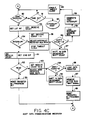
- Figure 4c is a flow chart of the logic steps for receiving data at the host controller;
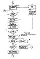
- Figure 5a is a flow chart of the logic steps for transmitting data from a remote terminal; and
- Figure 5b is a flow chart of the logic steps for receiving data at the remote terminal.
- Figure 1 is a block diagram of the graphics terminal system for a remote terminal and host controller according to the present invention.
Printer 15,modem 17,mouse 19, keyboard 21 andvideo display unit 23 are input/output devices for a personal computer that are well known in the art. Remote terminal 14 comprisesparallel port 13,serial port 16,serial port 18, keyboard interface unit 20graphics controller 22 andvideo memory unit 24 which are hardware elements of a personal computer well known in the art as found on the IBM XT or AT series PC.Elements remote terminal bus 27. Remoteterminal bus 27 also exchanges data with a fiber optic transmitter/receiver unit 9 through MFM encode/decode unit 10 and shift register 11 under the control of terminal logic controller 12. The MFM unit operates on a pulsed form of the Miller code.Host controller 1 comprises ahost data bus 26 which exchanges data with fiber optic transmit receiveunit 5 throughbus buffer 2, FIFO register 3 and MFM encode/decode unit 4 under the control ofhost controller 8. Alternately, other encode/decode methods could be used such as Manchester II or 4B5B - The interactive hardware logic and communications system of the
host controller 1 and remote terminal 14 are constructed such that remoteterminal bus 27 appears to physically reside in a memory unit accessible to hostbus 26. Thus, data from remoteterminal bus 27 may be accessed as data from a conventional memory unit. Address and input/output decoder unit 7 accept commands from thehost bus 26 in combination withhost logic controller 8,bus buffers 2, FIFO unit 3 andshift register 6. Selective transfer commands are directed to the remote terminal 14 through MFM encoder/decoder unit 4. - Fiber optic transmit and receive
units 5 and 9 may be any optical fiber transmission system that is capable of transmitting at 25 megahertz or higher, one such system being manufactured by the Hewlett Packard Corporation of San Jose, CA. Fiber optic transmit/receiveunits 5 and 9 use a duplex cable having two fiber optic cables. One fiber optic cable carries signals fromhost controller 1 to remote terminal 14 while the second cable carries signals from remote terminal 14 to hostcontroller 1. Also, fiber optic cable is preferred over coaxial cable because fiber optic cable can transmit data at a faster speed that is more appropriate for handling the high speed serial data transmission required by the present invention. Fiber optic cable does not emit electromagnetic radiation and is not susceptible to electromagnetic interference as is coaxial cable. - The MFM encode/
decode units logic controllers 8 and 12 are made from 74F series high speed TTL logic such as manufactured by Fairchild. The logic is preferably hardwired to form a Richardson controller that is specially dedicated to the specific task of controlling data processing. The controllers encode parallel data from one data bus into a serial data stream and decode the serial data back to a parallel stream in the format of the receiving bus "on the fly", in real time as the data is generated. The logic controllers might be replaced with a general purpose microprocessor capable of executing the programming with sufficient speed, although no microprocessor known at present has sufficient processing speed. Thebus buffer 2, address and decodeunit 7, FIFO unit 3 andshift registers 6 and 11 may be made from slower speed LS logic.Host bus 26 may be any of several data bus configurations such as Multibus, VME, Q-BUS, or the data bus used on the IBM Models XT and AT personal computers. The FIFO units 3 and 11, however, should not be used with this later bus because the period of time required to empty the FIFO may exceed the time needed to refresh the bus. With a higher performance bus, however, the FIFO enables thehost controller 8 to continue transferring data to the remote terminal while the CPU on the host bus does something else. Thus, the FIFO's reduce the number of times that the CPU must address each remote terminal. - As presently contemplated,
host logic controller 8 and terminal logic controller 12 provide all timing and control functions necessary to transfer data between the remote terminal and host controller. To ensure that the remote terminal is physically "mapped" onto the host controller, it is necessary that the encode, decode and transfer operations occur on the fly, which typically involves processing at very high speed such as 25MHz or higher. The data bus is dedicated primarily to updating the video memory with much less time processing time being spent communicating with the CPU. - The type of data bus used at the host controller or remote terminal may establish a minimum rate for data transfer. Some busses, such as found on the IBM XT and AT series personal computer, require that the video memory be periodically refreshed. If too much time is spent in video write, the refresh time is exceeded and the memory lost. If the transfer rate is too slow, the refresh time is exceeded before a complete message is stored. While the minimum time varies depending on the particular data bus, it is believed that the transfer rate must be at least 15 Megabits/sec. It is to be appreciated, however, that a higher performance data bus that does not need to be periodically refreshed does not have a minimum transfer rate.
- Address and input/
output decoder 7 transfers requests for memory and output write commands fromhost bus 26 to hostlogic controller 8. The host controller coordinates the transfer of data throughbus buffers 2 and optional FIFO 3 orshift register 6. The serialized data is encoded by MFM encode and decodeunit 4 for transmission byfiber optic transmitter 5. - A signal receiver in fiber optic transmitter/receiver unit 9 receives the optical signal and transfers data to a MFM encode/
decode Unit 10. The incoming signal is buffered in shift register unit 11 until terminal logic controller 12 determines that the transmission is complete. The terminal controller then provides control and timing information to remoteterminal bus 27 so that the output from shift register 11 may be directed to the appropriate output port or memory location. After a period of time sufficient to transfer data, terminal logic controller 12 sends an acknowledgment signal to the host controller. The format of the acknowledgment signal is illustrated in Figure 3c. -
Host data bus 26 generates memory and input read commands in the same manner as described above with two exceptions. The first exception is that the CPU of the host controller (not shown) must wait for all previously received access requests to the terminal to be emptied from the buffer before receiving the next read information and resuming normal operation. The second exception is that the terminal controller 12 must use a slightly different data format, shown of figure 3b, to return the requested data from a memory or input port. - Terminal controller 12 generates an interrupt to the
host controller 8 to request an interrupt onhost bus 26 in response to an interrupt generated by any of the peripheral devises 15, 17, 19 or 21. Thehost controller 8 maintains the information on the source of the interrupt in address and decodeunit 7 for transfer to hostdata bus 26. - Figure 2 illustrates the format for data contained in a host initiated command. The first two bits of the frame, A and B, determine whether the command is a read or write command and whether the data transfer is directed to an I/O port or to a memory device. The bits that follow contain the address of the data. Data bits follow the address only if the command is a write command. Thus, placing the read/write bits in front of the address eliminates having to read the eight bits of address when the command is a read command.
- Figure 3a illustrates an interrupt request directed from the remote terminal to the host controller. A true value in the first bit indicates that the received message is an interrupt address. The remaining bits define the address of the source of the interrupt.
- Figure 3b illustrates the format of the data format for acknowledging a read command. The first bit is a 0 or "false" followed by a 0 or "false". The following bits contain the data requested by the host controller.
- Figure 3c illustrates the data format in which the interrupt bit is set to 0 or "false" and the read bit is set to 1 or "true" in order to acknowledge the receipt of a write command.
- The transmission of the data between the host controller may be done either in a synchronous or asynchronous format. The synchronous format is conceptually easier to implement but requires more processing hardware to distinguish between a null transmission and real data. In addition to requiring less hardware, the asynchronous format is faster because the logic controllers need not recognize a data transmission since no signal is transmitted unless data is also being transmitted. The asynchronous format, however, is more difficult to implement. The preferred embodiment of the present invention comprises a hybrid transmission format in which synchronous data transmissions are transmitted asynchronously. The logic controllers have no difficulty in recognizing data because no signal is transmitted unless data is also present. The process of decoding the data at the receiving controller, however, is essentially that for decoding synchronous data. The hybrid transmission format set forth in detail below is considered to produce the maximum rate of data transfer with the minimum amount and complexity of hardware.
- Figure 4a is a flow chart of logic operations at the host controller that occur in response to an initiation request from the host bus. The host controller remains in an idle state until a bus access occurs at
step 28. If the request from the host is a "read" request atstep 29, a wait request line is activated atstep 30. Thehost controller 8 then waits until room is available in FIFO memory buffer 3. Once space is available, the controller clocks the bus address atstep 32 and saves the command type atstep 33. A "FIFO command pending" flag is set atstep 40 which initiates the processing steps shown in Figure 4b. If the command was not a "read" atstep 29, then thecontroller 8 determines atstep 34 if the FIFO buffer is full. If the FIFO buffer is full, a wait line to the host is set atstep 35 and the FIFO status is monitored atstep 36 until space is available at which time the wait line is removed asstep 37. The address and data is then clocked in at the end of the next cycle asstep 38 and the command type is saved at step 39. The "FIFO command pending" flag is set which activates the process shown in Fig 4b. If the FIFO was not full atstep 34, the address and data is clocked in atstep 38, the command type is saved at step 39 and the "FIFO command pending" flag is set atstep 40. - Figure 4b describes the host data communications transmitter operations. The
host logic controller 8 monitors the FIFO command pending flag atstep 44. When the flag is set, the controller waits if another transfer is in process asstep 42. Once the previous transfer is complete, synchronization SYNC bits are transmitted, the shift register is loaded, the shift counter is set for read or write as appropriate, a "transfer-in-progress" flag is set, and the command is loaded atstep 43. A delay occurs until SYNC is completed atstep 44 at which time the shift register clocks are enabled atstep 45. The shift counter is tested for equality to zero atstep 46. If not equal to zero, the counter is decremented atstep 47 and checked again atstep 46. When the counter equals zero, a time-out counter is initiated atstep 48 and the receive counter is set equal to 2 atstep 49. - Figure 4c illustrates the host data communications receiver logic which begins awaiting a response from the remote terminal 14. The
MFM decoder 4 is monitored forSYNC step 50 or a time-out counter step 51. If a time-out occurs, the host processor is interrupted atstep 52 to signify an error condition. If the SYNC is received atstep 50, thehost controller 8 extracts the first bit and decrements the receive count atstep 53. The host controller then checks the first bit to see if it is an interrupt atstep 54. If so, the controller sets the receive count equal to 4, selects the interrupt register multiplexer path and stops the time-out clock atstep 55. The shift count is tested for equality to zero atstep 56. If the shift count is not equal to zero atstep 56, an interrupt is generated atstep 59 and the time-out clock is enabled atstep 60. The process then reenters the loop which tests for SYNC received atstep 50 and a time-out atstep 51. If the first bit detected atstep 53 was not an interrupt atstep 54, then the receive count is decremented and the second bit extracted atstep 61. The second bit is tested for a read value atstep 62 which, if "true", sets the receive count equal to 8 and selects the read register multiplexer path atstep 63. The shift count is tested for equality to zero atstep 64 which, if not true, shifts counts equals zero and decrements the shift register atstep 65. When the shift count equals zero, the data register is loaded at step 66, the host bus wait signal is deactivated atstep 67, and the "transfer-in-progress" bit is reset atstep 68. If the second bit atstep 61 is not a read atstep 62, the "transfer-in-progress" bit is rest. After the "transfer-in-progress" bit is reset at eithersteps step 41. - Figure 5b is a flow chart of the functions of the data communications receiver for the remote terminal. The terminal logic controller 12 begins by continuously testing for received SYNC at
step 80, and an interrupt pending flag atstep 81. If SYNC is received atstep 80, a "cycle-in-progress" bit is set atstep 82 and the first bit is extracted and tested for a "true" read value atstep 84. A read command sets the receive count equal to 17 and selects the read multiplexer path atstep 85. The shift count is tested for zero atstep 86 which, if false, shifts data and decrement the shift counter atstep 87. When the shift count equals zero, the address and command registers are loaded atstep 88 and the parallel cycle is initiated at step 89. If the first bit atstep 83 is not a read atstep 84, then the receive count is set equal to 25 atstep 90 and the write multiplexer path is selected atstep 91. The shift count is checked for zero atstep 92 which, if "false", shifts the data and decrement the shift count asstep 95. When the shift count does equal zero, the address, command, and data registers are loaded atstep 93 and the parallel cycle is initiated atstep 94. - Figure 5a is a flow chart of the logic steps involved in transmitting communications data from the host controller to the remote terminal. Once the parallel cycle has been initiated from either a read command at step 89 or a write command at
step 94, the terminal logic controller 12 waits for the completion of the parallel cycle atstep 71. The terminal logic controller then sends a SYNC, loads the shift registers, sets the shift counters for read or write as appropriate, and sets the "transfer-in-progress" bit atstep 72. The terminal controller waits for the end of the SYNC pattern atstep 73 at which time the terminal controller enables the shift register clocks at step 74. The shift counter is checked for zero atstep 75 and decremented if not equal to zero atstep 76. If the shift count does equal zero atstep 75, the controller determines if a command cycle exists atstep 77 which, if "true", resets the command "cycle-in-progress" bit atstep 79. If the command cycle is not true atstep 77, the "interrupt-in-progress" bit is set atstep 78 and the processing returns to testing for received SYNC and an interrupt pending atstep 81. If an interrupt is pending atstep 81, the "interrupt-in-progress" bit is set atstep 69, SYNC is initiated, the shift registers are loaded and the shift register counter is set for interrupt. The interrupt message is then transmitted to the host in the same manner as a read or write message as previously described. At the end of the interrupt message the "interrupt-in-progress" flag is reset. The controller 12 begins testing for SYNC atstep 80 as previously described. - The principles, preferred embodiments and modes of operation of the present invention have been described in the foregoing specification. The invention which is intended to be protected herein, however, should not be construed as limited to the particular forms described as these are to be regarded as illustrative rather than restrictive. Variations and changes may be made by those skilled in the art without departing from the spirit of the invention. Accordingly, the foregoing detailed description should be considered exemplary in nature and as not as limiting to the scope and spirit of the invention set forth in the appended claims.
Claims (22)
a first data bus having a plurality of parallel command streams, each command stream comprising data;
a second data bus having a plurality of parallel command streams, each command stream comprising data, said second data bus being remote from said first data bus;
means for transmitting data from said first data bus to said second data bus so that said first data bus is local to said second data bus.
said first data bus comprises a host controller having a central processing unit (CPU) for executing software;
said second data bus comprises a remote terminal, said remote terminal having a video display and associated video memory.
means for encoding data on each of said command streams from said first data bus into serialized data;
means for transmitting said serialized data from said first data bus to said second data bus;
control means for controlling the encoding and transmitting means at said first data bus;
means for receiving serialized data from said second data bus at said first data bus;
means for decoding said serialized data from said second data bus into parallel streams of data at first data bus; and
control means for controlling the receiving and decoding means at said first data bus.
means for receiving serialized data from said first data bus at said second data bus;
means for decoding said serialized data into parallel streams of data at said second data bus;
control means for controlling the receiving and decoding means at said second data bus;
means for encoding data on each of said command streams from said second data bus into serialized data;
means for transmitting said serialized data from said second data bus to said first data bus; and
control means for controlling the encoding and transmitting means at said second data bus.
said means for transmitting data from said first data bus to said second data bus comprises a first transmission channel for transmitting a first single stream of encoded data; and
said means for transmitting data from said second data bus to said first data bus comprises a second transmission channel for transmitting a second single stream of encoded data.
said first transmission channel comprises a fiber optic link; and
said second transmission channel comprises a fiber optic link.
said means for transmitting data from said first data bus to said second data bus comprises means for transmitting said data at a frequency of at least 15 MHz; and
said means for transmitting data from said second data bus to said first data bus comprises means for transmitting said data at a frequency of at least 15 MHz.
means for generating video graphics information on said first data bus;
means for receiving said video graphics information on said second data bus; and
means for displaying said video graphics information at said remote terminal.
transmitting data from a first data bus of a host controller to a second bus of a remote terminal that is remote from said first data bus so that said first data bus has direct access to said terminal bus, including any operational hardware on said second bus; and
transmitting data from said second bus to said first data bus so that said second bus has direct access to said first data bus, including any operational hardware on said first data bus.
said first data bus data comprises video graphics information; and
said terminal bus data comprises video graphics information.
Applications Claiming Priority (2)
| Application Number | Priority Date | Filing Date | Title |
|---|---|---|---|
| US93884886A | 1986-12-08 | 1986-12-08 | |
| US938848 | 1986-12-08 |
Publications (3)
| Publication Number | Publication Date |
|---|---|
| EP0270896A2 true EP0270896A2 (en) | 1988-06-15 |
| EP0270896A3 EP0270896A3 (en) | 1990-09-19 |
| EP0270896B1 EP0270896B1 (en) | 1997-04-09 |
Family
ID=25472062
Family Applications (1)
| Application Number | Title | Priority Date | Filing Date |
|---|---|---|---|
| EP87117245A Expired - Lifetime EP0270896B1 (en) | 1986-12-08 | 1987-11-23 | Data link and method of transferring data for personal computer system |
Country Status (4)
| Country | Link |
|---|---|
| EP (1) | EP0270896B1 (en) |
| AT (1) | ATE151544T1 (en) |
| CA (1) | CA1283962C (en) |
| DE (1) | DE3752047D1 (en) |
Cited By (6)
| Publication number | Priority date | Publication date | Assignee | Title |
|---|---|---|---|---|
| WO1993003440A1 (en) * | 1991-07-30 | 1993-02-18 | Pep Modular Computers Ag | High-speed bus system and process for operating same |
| US5251319A (en) * | 1989-04-07 | 1993-10-05 | Koden Industry Co., Ltd. | Optical transmission apparatus for digital devices |
| EP0576241A1 (en) * | 1992-06-24 | 1993-12-29 | International Business Machines Corporation | Computer system and system expansion unit |
| US6418494B1 (en) * | 1998-10-30 | 2002-07-09 | Cybex Computer Products Corporation | Split computer architecture to separate user and processor while retaining original user interface |
| US7783820B2 (en) | 2005-12-30 | 2010-08-24 | Avocent Corporation | Packet-switched split computer having disassociated peripheral controller and plural data buses |
| US9743095B2 (en) | 2002-10-01 | 2017-08-22 | Avocent Corporation | Video compression encoder |
Families Citing this family (3)
| Publication number | Priority date | Publication date | Assignee | Title |
|---|---|---|---|---|
| US9560371B2 (en) | 2003-07-30 | 2017-01-31 | Avocent Corporation | Video compression system |
| US7457461B2 (en) | 2004-06-25 | 2008-11-25 | Avocent Corporation | Video compression noise immunity |
| US7782961B2 (en) | 2006-04-28 | 2010-08-24 | Avocent Corporation | DVC delta commands |
Citations (7)
| Publication number | Priority date | Publication date | Assignee | Title |
|---|---|---|---|---|
| US4038644A (en) * | 1975-11-19 | 1977-07-26 | Ncr Corporation | Destination selection apparatus for a bus oriented computer system |
| JPS575139A (en) * | 1980-06-10 | 1982-01-11 | Toshiba Corp | Data transfer system between standard buses |
| EP0109337A2 (en) * | 1982-11-15 | 1984-05-23 | Pierre Jutier | Data processing device with a multi-microcomputer for image processing |
| JPS605371A (en) * | 1983-06-24 | 1985-01-11 | Oki Electric Ind Co Ltd | System bus extension system |
| US4577317A (en) * | 1983-04-15 | 1986-03-18 | Ics Electronics Corporation | Method for extending a parallel data bus |
| JPS61170160A (en) * | 1985-01-23 | 1986-07-31 | Matsushita Electric Ind Co Ltd | Input and output device of automatic equipment |
| EP0228124A1 (en) * | 1985-12-18 | 1987-07-08 | Koninklijke Philips Electronics N.V. | Bus system |
-
1987
- 1987-11-18 CA CA000552137A patent/CA1283962C/en not_active Expired - Fee Related
- 1987-11-23 DE DE3752047T patent/DE3752047D1/en not_active Expired - Lifetime
- 1987-11-23 EP EP87117245A patent/EP0270896B1/en not_active Expired - Lifetime
- 1987-11-23 AT AT87117245T patent/ATE151544T1/en not_active IP Right Cessation
Patent Citations (7)
| Publication number | Priority date | Publication date | Assignee | Title |
|---|---|---|---|---|
| US4038644A (en) * | 1975-11-19 | 1977-07-26 | Ncr Corporation | Destination selection apparatus for a bus oriented computer system |
| JPS575139A (en) * | 1980-06-10 | 1982-01-11 | Toshiba Corp | Data transfer system between standard buses |
| EP0109337A2 (en) * | 1982-11-15 | 1984-05-23 | Pierre Jutier | Data processing device with a multi-microcomputer for image processing |
| US4577317A (en) * | 1983-04-15 | 1986-03-18 | Ics Electronics Corporation | Method for extending a parallel data bus |
| JPS605371A (en) * | 1983-06-24 | 1985-01-11 | Oki Electric Ind Co Ltd | System bus extension system |
| JPS61170160A (en) * | 1985-01-23 | 1986-07-31 | Matsushita Electric Ind Co Ltd | Input and output device of automatic equipment |
| EP0228124A1 (en) * | 1985-12-18 | 1987-07-08 | Koninklijke Philips Electronics N.V. | Bus system |
Non-Patent Citations (3)
| Title |
|---|
| PATENT ABSTRACTS OF JAPAN, vol. 10, no. 379 (E-465)[2436], 18th December 1986; & JP-A-61 170 160 (MATSUSHITA ELECTRIC IND. CO., LTD) 31-07-1986 * |
| PATENT ABSTRACTS OF JAPAN, vol. 6, no. 62 (P-111)[940], 21st April 1982; & JP-A-57 005 139 (TOKYO SHIBAURA DENKI K.K.) 11-01-1982 * |
| PATENT ABSTRACTS OF JAPAN, vol. 9, no. 120 (P-358)[1843], 24th May 1985; & JP-A-60 005 371 (OKI DENKI KOGYO K.K.) 11-01-1985 * |
Cited By (9)
| Publication number | Priority date | Publication date | Assignee | Title |
|---|---|---|---|---|
| US5251319A (en) * | 1989-04-07 | 1993-10-05 | Koden Industry Co., Ltd. | Optical transmission apparatus for digital devices |
| WO1993003440A1 (en) * | 1991-07-30 | 1993-02-18 | Pep Modular Computers Ag | High-speed bus system and process for operating same |
| US5649124A (en) * | 1991-07-30 | 1997-07-15 | Pep Modular Computers Ag | High-speed bus system for simultaneous serial and parallel data transfer and a method of operating the system |
| EP0576241A1 (en) * | 1992-06-24 | 1993-12-29 | International Business Machines Corporation | Computer system and system expansion unit |
| US6418494B1 (en) * | 1998-10-30 | 2002-07-09 | Cybex Computer Products Corporation | Split computer architecture to separate user and processor while retaining original user interface |
| US6807639B2 (en) | 1998-10-30 | 2004-10-19 | Avocent Corporation | Split computer architecture to separate user and processor while retaining original user interface |
| US7020732B2 (en) | 1998-10-30 | 2006-03-28 | Avocent Huntsville Corporation | Split computer architecture |
| US9743095B2 (en) | 2002-10-01 | 2017-08-22 | Avocent Corporation | Video compression encoder |
| US7783820B2 (en) | 2005-12-30 | 2010-08-24 | Avocent Corporation | Packet-switched split computer having disassociated peripheral controller and plural data buses |
Also Published As
| Publication number | Publication date |
|---|---|
| DE3752047D1 (en) | 1997-05-15 |
| ATE151544T1 (en) | 1997-04-15 |
| EP0270896B1 (en) | 1997-04-09 |
| EP0270896A3 (en) | 1990-09-19 |
| CA1283962C (en) | 1991-05-07 |
Similar Documents
| Publication | Publication Date | Title |
|---|---|---|
| US5062059A (en) | Apparatus and method for communication between host CPU and remote terminal | |
| EP0063334B1 (en) | Data processing apparatus for a multiprocessor system | |
| US5063494A (en) | Programmable data communications controller | |
| US4488226A (en) | Method and apparatus for high speed asynchronous serial data transfer | |
| US4490788A (en) | Well-logging data processing system having segmented serial processor-to-peripheral data links | |
| US4570220A (en) | High speed parallel bus and data transfer method | |
| EP0137437B1 (en) | Method for initializing a token-passing local-area network | |
| US4562533A (en) | Data communications system to system adapter | |
| US4807109A (en) | High speed synchronous/asynchronous local bus and data transfer method | |
| US4868742A (en) | Input/output bus for system which generates a new header parcel when an interrupted data block transfer between a computer and peripherals is resumed | |
| US4322793A (en) | Communication controller transparently integrated into a host CPU | |
| US4041473A (en) | Computer input/output control apparatus | |
| EP0165600A2 (en) | Input/output bus for computer | |
| US20050033896A1 (en) | Systems and methods for batched USB data transfers | |
| US4156277A (en) | Access request mechanism for a serial data input/output system | |
| US5958024A (en) | System having a receive data register for storing at least nine data bits of frame and status bits indicating the status of asynchronous serial receiver | |
| JPH10177545A (en) | Bus communication system, bus arbitrating method, and data transferring method | |
| EP0534529A1 (en) | Apparatus and method for burst data transfer | |
| JPH04312160A (en) | Multiprocessor system and its message transmission and reception controller | |
| EP0293860B1 (en) | Peripheral controller and adapter interface | |
| US5463752A (en) | Method and system for enhancing the efficiency of communication between multiple direct access storage devices and a storage system controller | |
| EP0270896B1 (en) | Data link and method of transferring data for personal computer system | |
| EP0592213B1 (en) | Synchronous/asynchronous partitioning of an asynchronous bus interface | |
| JP2005504392A (en) | Bus system and bus interface | |
| US6799231B2 (en) | Virtual I/O device coupled to memory controller |
Legal Events
| Date | Code | Title | Description |
|---|---|---|---|
| PUAI | Public reference made under article 153(3) epc to a published international application that has entered the european phase |
Free format text: ORIGINAL CODE: 0009012 |
|
| AK | Designated contracting states |
Kind code of ref document: A2 Designated state(s): AT BE CH DE ES FR GB GR IT LI NL SE |
|
| PUAL | Search report despatched |
Free format text: ORIGINAL CODE: 0009013 |
|
| AK | Designated contracting states |
Kind code of ref document: A3 Designated state(s): AT BE CH DE ES FR GB GR IT LI NL SE |
|
| 17P | Request for examination filed |
Effective date: 19910319 |
|
| 17Q | First examination report despatched |
Effective date: 19921012 |
|
| GRAH | Despatch of communication of intention to grant a patent |
Free format text: ORIGINAL CODE: EPIDOS IGRA |
|
| GRAH | Despatch of communication of intention to grant a patent |
Free format text: ORIGINAL CODE: EPIDOS IGRA |
|
| GRAA | (expected) grant |
Free format text: ORIGINAL CODE: 0009210 |
|
| AK | Designated contracting states |
Kind code of ref document: B1 Designated state(s): AT BE CH DE ES FR GB GR IT LI NL SE |
|
| PG25 | Lapsed in a contracting state [announced via postgrant information from national office to epo] |
Ref country code: FR Effective date: 19970409 Ref country code: IT Free format text: LAPSE BECAUSE OF FAILURE TO SUBMIT A TRANSLATION OF THE DESCRIPTION OR TO PAY THE FEE WITHIN THE PRE;WARNING: LAPSES OF ITALIAN PATENTS WITH EFFECTIVE DATE BEFORE 2007 MAY HAVE OCCURRED AT ANY TIME BEFORE 2007. THE CORRECT EFFECTIVE DATE MAY BE DIFFERENT FROM THE ONE RECORDED.SCRIBED TIME-LIMIT Effective date: 19970409 Ref country code: AT Effective date: 19970409 Ref country code: BE Effective date: 19970409 Ref country code: CH Effective date: 19970409 Ref country code: GR Free format text: LAPSE BECAUSE OF FAILURE TO SUBMIT A TRANSLATION OF THE DESCRIPTION OR TO PAY THE FEE WITHIN THE PRESCRIBED TIME-LIMIT Effective date: 19970409 Ref country code: LI Effective date: 19970409 Ref country code: NL Effective date: 19970409 |
|
| REF | Corresponds to: |
Ref document number: 151544 Country of ref document: AT Date of ref document: 19970415 Kind code of ref document: T |
|
| REG | Reference to a national code |
Ref country code: CH Ref legal event code: EP |
|
| REF | Corresponds to: |
Ref document number: 3752047 Country of ref document: DE Date of ref document: 19970515 |
|
| PG25 | Lapsed in a contracting state [announced via postgrant information from national office to epo] |
Ref country code: SE Effective date: 19970709 |
|
| PG25 | Lapsed in a contracting state [announced via postgrant information from national office to epo] |
Ref country code: DE Effective date: 19970710 |
|
| NLV1 | Nl: lapsed or annulled due to failure to fulfill the requirements of art. 29p and 29m of the patents act | ||
| EN | Fr: translation not filed | ||
| REG | Reference to a national code |
Ref country code: CH Ref legal event code: PL |
|
| PG25 | Lapsed in a contracting state [announced via postgrant information from national office to epo] |
Ref country code: ES Free format text: LAPSE BECAUSE OF FAILURE TO SUBMIT A TRANSLATION OF THE DESCRIPTION OR TO PAY THE FEE WITHIN THE PRESCRIBED TIME-LIMIT Effective date: 19971023 |
|
| PG25 | Lapsed in a contracting state [announced via postgrant information from national office to epo] |
Ref country code: GB Free format text: LAPSE BECAUSE OF NON-PAYMENT OF DUE FEES Effective date: 19971123 |
|
| PLBE | No opposition filed within time limit |
Free format text: ORIGINAL CODE: 0009261 |
|
| STAA | Information on the status of an ep patent application or granted ep patent |
Free format text: STATUS: NO OPPOSITION FILED WITHIN TIME LIMIT |
|
| 26N | No opposition filed | ||
| GBPC | Gb: european patent ceased through non-payment of renewal fee |
Effective date: 19971123 |