EP0268909A2 - Process for manufacturing channels in cast pieces for conducting temperature-influencing mediums, and cast pieces for use as a temperature-controlled component or tool - Google Patents
Process for manufacturing channels in cast pieces for conducting temperature-influencing mediums, and cast pieces for use as a temperature-controlled component or tool Download PDFInfo
- Publication number
- EP0268909A2 EP0268909A2 EP87116455A EP87116455A EP0268909A2 EP 0268909 A2 EP0268909 A2 EP 0268909A2 EP 87116455 A EP87116455 A EP 87116455A EP 87116455 A EP87116455 A EP 87116455A EP 0268909 A2 EP0268909 A2 EP 0268909A2
- Authority
- EP
- European Patent Office
- Prior art keywords
- pipe system
- cast
- alloys
- cast body
- casting
- Prior art date
- Legal status (The legal status is an assumption and is not a legal conclusion. Google has not performed a legal analysis and makes no representation as to the accuracy of the status listed.)
- Withdrawn
Links
- 238000000034 method Methods 0.000 title claims description 16
- 238000004519 manufacturing process Methods 0.000 title description 3
- 238000005266 casting Methods 0.000 claims abstract description 45
- 239000000463 material Substances 0.000 claims abstract description 25
- RYGMFSIKBFXOCR-UHFFFAOYSA-N Copper Chemical compound [Cu] RYGMFSIKBFXOCR-UHFFFAOYSA-N 0.000 claims abstract description 12
- 239000010949 copper Substances 0.000 claims abstract description 12
- 229910052802 copper Inorganic materials 0.000 claims abstract description 12
- 229910052782 aluminium Inorganic materials 0.000 claims abstract description 11
- XAGFODPZIPBFFR-UHFFFAOYSA-N aluminium Chemical compound [Al] XAGFODPZIPBFFR-UHFFFAOYSA-N 0.000 claims abstract description 11
- 238000007711 solidification Methods 0.000 claims abstract description 10
- 230000008023 solidification Effects 0.000 claims abstract description 10
- 238000002844 melting Methods 0.000 claims abstract description 9
- 230000008018 melting Effects 0.000 claims abstract description 9
- 229910000831 Steel Inorganic materials 0.000 claims abstract description 8
- 239000002826 coolant Substances 0.000 claims abstract description 8
- 239000000155 melt Substances 0.000 claims abstract description 8
- 239000010959 steel Substances 0.000 claims abstract description 8
- 229910045601 alloy Inorganic materials 0.000 claims description 26
- 239000000956 alloy Substances 0.000 claims description 26
- XEEYBQQBJWHFJM-UHFFFAOYSA-N Iron Chemical compound [Fe] XEEYBQQBJWHFJM-UHFFFAOYSA-N 0.000 claims description 8
- HCHKCACWOHOZIP-UHFFFAOYSA-N Zinc Chemical compound [Zn] HCHKCACWOHOZIP-UHFFFAOYSA-N 0.000 claims description 6
- 229910052725 zinc Inorganic materials 0.000 claims description 6
- 239000011701 zinc Substances 0.000 claims description 6
- 229910052751 metal Inorganic materials 0.000 claims description 5
- 239000002184 metal Substances 0.000 claims description 5
- PXHVJJICTQNCMI-UHFFFAOYSA-N Nickel Chemical compound [Ni] PXHVJJICTQNCMI-UHFFFAOYSA-N 0.000 claims description 4
- 229910052742 iron Inorganic materials 0.000 claims description 4
- 230000015572 biosynthetic process Effects 0.000 claims description 3
- CWYNVVGOOAEACU-UHFFFAOYSA-N Fe2+ Chemical compound [Fe+2] CWYNVVGOOAEACU-UHFFFAOYSA-N 0.000 claims description 2
- FYYHWMGAXLPEAU-UHFFFAOYSA-N Magnesium Chemical compound [Mg] FYYHWMGAXLPEAU-UHFFFAOYSA-N 0.000 claims description 2
- ATJFFYVFTNAWJD-UHFFFAOYSA-N Tin Chemical compound [Sn] ATJFFYVFTNAWJD-UHFFFAOYSA-N 0.000 claims description 2
- RTAQQCXQSZGOHL-UHFFFAOYSA-N Titanium Chemical compound [Ti] RTAQQCXQSZGOHL-UHFFFAOYSA-N 0.000 claims description 2
- 229910052749 magnesium Inorganic materials 0.000 claims description 2
- 239000011777 magnesium Substances 0.000 claims description 2
- 238000005058 metal casting Methods 0.000 claims description 2
- 229910052759 nickel Inorganic materials 0.000 claims description 2
- 239000000126 substance Substances 0.000 claims description 2
- 239000010936 titanium Substances 0.000 claims description 2
- 229910052719 titanium Inorganic materials 0.000 claims description 2
- 238000001816 cooling Methods 0.000 abstract description 13
- 239000004411 aluminium Substances 0.000 abstract 1
- 238000010438 heat treatment Methods 0.000 description 4
- 238000004512 die casting Methods 0.000 description 3
- 239000007788 liquid Substances 0.000 description 3
- IJGRMHOSHXDMSA-UHFFFAOYSA-N Atomic nitrogen Chemical compound N#N IJGRMHOSHXDMSA-UHFFFAOYSA-N 0.000 description 2
- 229910001018 Cast iron Inorganic materials 0.000 description 2
- 229910001208 Crucible steel Inorganic materials 0.000 description 2
- 239000002253 acid Substances 0.000 description 2
- 238000009749 continuous casting Methods 0.000 description 2
- 239000007789 gas Substances 0.000 description 2
- VYZAMTAEIAYCRO-UHFFFAOYSA-N Chromium Chemical compound [Cr] VYZAMTAEIAYCRO-UHFFFAOYSA-N 0.000 description 1
- 229910001141 Ductile iron Inorganic materials 0.000 description 1
- 229910001060 Gray iron Inorganic materials 0.000 description 1
- 230000006978 adaptation Effects 0.000 description 1
- 239000007795 chemical reaction product Substances 0.000 description 1
- 239000002131 composite material Substances 0.000 description 1
- 238000011109 contamination Methods 0.000 description 1
- 238000005553 drilling Methods 0.000 description 1
- 230000005684 electric field Effects 0.000 description 1
- 239000000839 emulsion Substances 0.000 description 1
- 230000001771 impaired effect Effects 0.000 description 1
- 238000010297 mechanical methods and process Methods 0.000 description 1
- 239000000203 mixture Substances 0.000 description 1
- 229910052757 nitrogen Inorganic materials 0.000 description 1
- 239000003921 oil Substances 0.000 description 1
- 238000001556 precipitation Methods 0.000 description 1
- 230000002028 premature Effects 0.000 description 1
- 239000000047 product Substances 0.000 description 1
- XLYOFNOQVPJJNP-UHFFFAOYSA-N water Substances O XLYOFNOQVPJJNP-UHFFFAOYSA-N 0.000 description 1
- 238000003466 welding Methods 0.000 description 1
Images
Classifications
-
- B—PERFORMING OPERATIONS; TRANSPORTING
- B22—CASTING; POWDER METALLURGY
- B22C—FOUNDRY MOULDING
- B22C9/00—Moulds or cores; Moulding processes
- B22C9/10—Cores; Manufacture or installation of cores
-
- B—PERFORMING OPERATIONS; TRANSPORTING
- B22—CASTING; POWDER METALLURGY
- B22D—CASTING OF METALS; CASTING OF OTHER SUBSTANCES BY THE SAME PROCESSES OR DEVICES
- B22D19/00—Casting in, on, or around objects which form part of the product
- B22D19/0072—Casting in, on, or around objects which form part of the product for making objects with integrated channels
Definitions
- the invention relates to a method for the formation of channels in castings, in particular in metal castings, for the passage of media for influencing the temperature, the channels being laid as a pipe system in any form as an auxiliary core in the casting mold before the casting process and wherein the pipe system of coolant during the casting process is flowed through.
- Castings or castings with channels for heat transfer are required for many technical applications in order to avoid undesirably high temperatures or to set certain temperatures (e.g. cooling and heating up of die casting molds for casting crankcases).
- the ducts have generally been manufactured mechanically (e.g. by drilling).
- the channels are difficult to form mechanically as spirals, spirals and arches.
- these mechanical methods then have the particular disadvantage that they cannot be used to produce uniform distances from the heat exchanger surfaces of the media channels. These unequal distances lead to different cooling or warming-up conditions.
- German Offenlegungsschrift 32 43 377 in the case of a workpiece with a molded channel, a metal component with a cross-section consisting of two or more parts is inserted into the mold before the introduction of the melt, which component is cast into the workpiece or partially cast with it.
- a cast workpiece made of steel, gray cast iron or nodular cast iron with a dimensionally stable channel which can be designed in any shape and thus to be aerodynamic.
- a hollow body consisting of materials with different melting points is inserted into the mold as a metallic component and the outer part is to fuse with the cast material.
- the process is also very expensive to manufacture. The heat transfer conditions in the finished cast body cannot be significantly improved due to the existing material inhomogeneities.
- German patent 7 26 599 describes a method for encapsulating tubular bodies, in particular multiply bent bodies or bodies having a small internal diameter, with metal of the same or higher melting point, while passing gases or liquids through the tube, the gas used for cooling or the Liquid is passed through the tube under an adjustable back pressure, which approximately keeps the deformation resistance of the tube at its softening temperature.
- a composite casting is to be produced, which offers a reliable guarantee of perfect welding at all points between the pipe and the casting metal.
- a removal of the tube is not provided for in this document, since a bond between the tube and the cast body is to be produced, with the same disadvantages due to the material inhomogeneities, as has already been described above.
- the object of the invention is to present a method for forming channels and a cast body, while avoiding the disadvantages mentioned, with an arbitrary position of the channels and a uniform, optimal heat transfer can be guaranteed in any way.
- the cast body should be easy and inexpensive to manufacture and process.
- the pipe system is removed during or after the solidification of the cast body.
- the pipe system is therefore removed in order to achieve optimal heat transfer conditions in the end product, e.g. B. in a die casting mold or in a continuous casting roll.
- the pipe systems to be removed from the cast body later can be easily adapted to the contour of the mold or the cast body, whereby equal distances from the heat transfer surfaces to achieve uniform heat transfer conditions (e.g. when heating die casting molds or the aluminum, plastic products to be produced therein, etc. . and later cooling of the castings) can be set.
- a lower melting material is used for the pipe system than for the cast body. In this way, a particularly simple removal of the pipe system after casting is made possible. Coolant flows through the pipe system to be removed later during the casting process, thereby preventing the pipe system from melting in time.
- Different coolants advantageously flow through the pipe system simultaneously or in succession.
- different cooling conditions or characteristics can be easily achieved within wide limits can be varied.
- the solidification and further cooling of the cast body can be controlled and influenced at the same time, for example also by heating or temporarily maintaining the temperature, in order to produce certain desired material properties.
- This can, for. B. with certain mold materials, e.g. As chrome-molybdenum-vanadium steels (material numbers 1.2343 and 1.2344), a chrome carbide precipitation is largely prevented and a fine-grained primary structure can be achieved.
- the pipe system is melted in order to remove it and the melt is driven out by means of a pressurized medium, preferably compressed air.
- a pressurized medium preferably compressed air.
- the residual heat of the cast body is used particularly advantageously for melting the pipe system, in the best case the cooling of the pipe system being switched off at a temperature above the melting temperature of the pipe system but below the solidification temperature of the cast body and the residual heat then being sufficient to melt the pipe system.
- Such a procedure significantly reduces energy costs.
- the object of the invention is achieved for a cast body with channels for the passage of media for influencing the temperature in that the cast body, when used as intended, consists of only a homogeneous material, the external dimensions of the pipe system forming the internal dimensions of the channels.
- the pipe system can be removed in a particularly advantageous manner, so that no materials of different thermal conductivity and no undesired cavities remain between the pipe system and the cast body in the cast body.
- the pipe system which can be easily removed during or after solidification, can be adapted to any shape with great advantage, so that ideal heat transfer conditions, depending on the type of use, e.g. can be set as a die for heating and cooling during casting or in relation to the later use of the casting as a component.
- the pipe system to be removed can also consist of a material that melts much lower than the cast body and preferably has good heat conductivity.
- a material that is chemically or electrochemically soluble in relation to the cast body can also be used advantageously for the pipe system.
- the pipe system to be removed consists of a non-ferrous metal, preferably copper, aluminum or their alloys.
- the pipe system consists of aluminum or its alloys; for cast bodies made of aluminum or its alloys, zinc or its alloys or plastic is preferably selected as the material.
- the pipe system to be removed expediently consists of steel, iron, copper or their alloys.
- lead or its alloys are used for the pipe system to be removed, for castings made of magnesium or its alloys zinc, tin, lead or their alloys.
- copper, aluminum or their alloys are expediently used for the pipe system to be removed.
- the mold (1) has a cavity (2) in which after the casting process and the solidification of the casting material, for. B. cast steel forms the cast body (3).
- hollow bodies in the form of a pipe system (4) with flow through them are inserted into the cavity (2) and guided through the wall of the casting mold (1) at a suitable point with inlet (5) and outlet (6).
- the pipe system (4) is flowed through by coolant (7, 8) to prevent premature melting and to achieve uniform cooling conditions as well as the desired material properties, which can be different media (e.g. water, oil, emulsions, liquid nitrogen etc .),
- the feed lines are designed switchable.
- the pipe system (4) is removed during or after the solidification of the cast body (3).
- the pipe system (4) located in the cast body (3) and later to be removed advantageously consists of a material that melts lower than the cast body (3).
- copper can be used for the cooling pipes for cast steel and aluminum for cast copper.
- the cast body (3) when used as intended, consists of only one homogeneous material, the external dimensions of the pipe system (4) being the same Form the internal dimensions of the channels.
- the lines of the pipe system can have any cross-sections, can be shaped in any way and can also lie on top of one another in multiple layers.
- the respective structural design is left to the person skilled in the art in adaptation to the later use of the cast body.
Abstract
Description
Die Erfindung betrifft ein Verfahren zur Bildung von Kanälen in Gußkörpern, insbesondere in Metallgußkörpern, für das Durchleiten von Medien zur Temperaturbeeinflussung, wobei die Kanäle als Rohrsystem in beliebiger Form als Hilfskern in der Gußform vor dem Gießvorgang verlegt und wobei während des Gießvorganges das Rohrsystem von Kühlmittel durchströmt wird.The invention relates to a method for the formation of channels in castings, in particular in metal castings, for the passage of media for influencing the temperature, the channels being laid as a pipe system in any form as an auxiliary core in the casting mold before the casting process and wherein the pipe system of coolant during the casting process is flowed through.
Für viele technische Anwendungen werden Gußkörper bzw. Gußteile mit Kanälen zur Wärmeübertragung benötigt, um unerwünscht hohe Temperaturen zu vermeiden oder bestimmte Temperaturen einzustellen (z. B. Kühlen und Aufwärmen von Druckgußformen zum Gießen von Kurbelgehäusen). Bisher werden die Kanäle im allgemeinen nachträglich auf mechanischem Wege (z. B. durch Bohren) hergestellt. Dabei lassen sich die Kanäle auf mechanischem Wege schlecht als Wendeln, Spiralen und Bögen ausbilden. Diese mechanischen Verfahren haben bei gekrümmten Oberflächen des Gußkörpers dann insbesondere den Nachteil, daß man mit ihnen keine gleichmäßigen Abstände zu den Wärmetauscherflächen der Medienkanäle erzeugen kann. Diese ungleichen Abstände führen zu unterschiedlichen Kühl- bzw. Aufwärmverhältnissen.Castings or castings with channels for heat transfer are required for many technical applications in order to avoid undesirably high temperatures or to set certain temperatures (e.g. cooling and heating up of die casting molds for casting crankcases). So far, the ducts have generally been manufactured mechanically (e.g. by drilling). The channels are difficult to form mechanically as spirals, spirals and arches. In the case of curved surfaces of the cast body, these mechanical methods then have the particular disadvantage that they cannot be used to produce uniform distances from the heat exchanger surfaces of the media channels. These unequal distances lead to different cooling or warming-up conditions.
Ein weiteres bekanntes, aber selten angewandtes Verfahren ist das Eingießen von Rohren; dieses Verfahren hat den Nachteil, daß das Rohrsystem im Gußkörper verbleibt und durch Hohlräume, Spaltbildng und Verschmutzung zwischen Rohrsystem und Gußkörper der Wärmeübergang erheblich beeinträchtigt und die gewünschte Temperaturbeeinflussung des Gußkörpers nicht erreicht wird.Another well-known but rarely used method is the pouring of pipes; This method has the disadvantage that the pipe system remains in the casting and the heat transfer is considerably impaired by cavities, gap formation and contamination between the pipe system and the casting and the desired temperature influence on the casting is not achieved.
An der deutschen Offenlegungsschrift 32 43 377 wird bei einem Werkstück mit eingeformtem Kanal in die Form vor dem Einbringen der Schmelze ein mit dem Kanal versehenes metallisches im Querschnitt zwei- oder mehrteiliges Bauteil eingelegt, das in das Werkstück eingegossen bzw. mit diesem teilweise vergossen wird. Auf diese Weise ist es möglich, ein Gußwerkstück aus Stahl, Grau- oder Sphäroguß mit einem maßhaltigen Kanal zu versehen, der in seiner Formgebung beliebig und somit strömungsgünstig zu gestalten ist. Dabei ist auch vorgesehen, daß als metallisches Bauteil ein aus Materialien mit unterschiedlichen Schmelzpunkten bestehender Hohlkörper in die Form eingelegt wird und wobei der äußere Teil mit dem Gußwerkstoff verschmelzen soll. Neben einem hohen Kostenaufwand für spezielle Materialien ist das Verfahren auch fertigungstechnisch sehr aufwendig. Die Wärmeübergangsbedingungen im fertigen Gußkörper können infolge der bestehenden Materialinhomogenitäten nicht entscheidend verbessert werden.In German Offenlegungsschrift 32 43 377, in the case of a workpiece with a molded channel, a metal component with a cross-section consisting of two or more parts is inserted into the mold before the introduction of the melt, which component is cast into the workpiece or partially cast with it. In this way it is possible to provide a cast workpiece made of steel, gray cast iron or nodular cast iron with a dimensionally stable channel, which can be designed in any shape and thus to be aerodynamic. It is also provided that a hollow body consisting of materials with different melting points is inserted into the mold as a metallic component and the outer part is to fuse with the cast material. In addition to the high cost of special materials, the process is also very expensive to manufacture. The heat transfer conditions in the finished cast body cannot be significantly improved due to the existing material inhomogeneities.
Aus der französischen Patentanmeldung 23 05 257 ist ein Rohr mit Innenkühlung, insbesondere für Stranggußanlagen bekannt, mit mindestens einem Innenrohr, durch das ein Kühlmedium hindurchläuft sowie mit Zu- und Abfuhreinrichtungen für dieses Medium, wobei die Leitung bzw. die Leitungen, Zuund/oder Abfuhreinrichtungen in den Rollenkörper gegossen werden. Das Rohr- bzw. Leitungssystem besteht aus herkömmlichen Stahlrohren, die vom Gußkörper aus Grauguß oder Stahlguß umgossen sind und im Gußkörper verbleiben mit den bereits geschilderten Nachteilen.From French patent application 23 05 257 a tube with internal cooling, in particular for continuous casting plants, is known, with at least one Inner tube through which a cooling medium runs and with supply and discharge devices for this medium, the line or lines, supply and / or discharge devices being poured into the reel body. The pipe or line system consists of conventional steel pipes, which are cast around the cast iron or cast iron body and remain in the cast body with the disadvantages already described.
In der deutschen Patentschrift 7 26 599 wird ein Verfahren zum Umgießen rohrartiger, insbesondere mehrfach gebogener oder eine geringe lichte Weite aufweisender Körper mit Metall von demselben oder höheren Schmelzpunkt unter Durchleiten von Gasen oder Flüssigkeiten durch das Rohr beschrieben, wobei das zur Kühlung dienende Gas oder die Flüssigkeit unter einem regelbaren Gegendruck durch das Rohr geleitet wird, der dem Verformungswiderstand des Rohres bei seiner Erweichungstemperatur annähernd die Waage hält. Auf diese Weise soll ein Verbundgußkörper hergestellt werden, der eine sichere Gewähr für eine einwandfreie Verschweißung an allen Stellen zwischen Rohr und Umgußmetall bietet. Eine Entfernung des Rohres ist nach dieser Druckschrift nicht vorgesehen, da ein Verbund zwischen Rohr und Gußkörper erzeugt werden soll, mit den gleichen Nachteilen aufgrund der Materialinhomogenitäten, wie bereits vorstehend beschrieben wurde.
Aufgabe der Erfindung ist es, unter Vermeidung der genannten Nachteile ein Verfahren zur Bildung von Kanälen sowie einen Gußkörper vorzustellen, wobei eine beliebige Lage der Kanäle und ein gleichmäßiger, optimaler Wärmeübergang in beliebiger Weise gewährleistet werden kann. Der Gußkörper soll leicht und kostengünstig herstellbar und bearbeitbar sein.The object of the invention is to present a method for forming channels and a cast body, while avoiding the disadvantages mentioned, with an arbitrary position of the channels and a uniform, optimal heat transfer can be guaranteed in any way. The cast body should be easy and inexpensive to manufacture and process.
Die Lösung der gestellten Aufgabe gelingt nach dem neuen Verfahren dadurch, daß das Rohrsystem während oder nach der Erstarrung des Gußkörpers entfernt wird. Nach der Erfindung wird das Rohrsystem deshalb entfernt, um optimale Wärmeübergangsverhältnisse im Endprodukt, z. B. in einer Druckgußkokille oder in einer Stranggießrolle zu schaffen. Die aus dem Gußkörper später zu entfernenden Rohrsysteme lassen sich gut der Kontur der Gußform bzw. dem Gußkörper anpassen, wodurch gleiche Abstände zu den wärmeübertragenden Flächen zur Erreichung gleichmäßiger Wärmeübergangsverhältnisse (z.B beim Erwärmen von Druckgußformen bzw. der darin zu erzeugenden Aluminium-, Kunststoffprodukte, etc. und späterer Abkühlung der Gußteile) eingestellt werden können. Nach der Erfindung ist insbesondere vorgesehen, daß für das Rohrsystem ein niedriger schmelzendes Material als für den Gußkörper verwendet wird. Auf diese Weise wird eine besonders einfache Entfernung des Rohrsystems nach dem Gießen ermöglicht. Das später zu entfernende Rohrsystem wird während des Gießvorganges von Kühlmittel durchströmt, wodurch ein zeitiges Aufschmelzen des Rohrsystems verhindert wird.The problem is solved by the new method in that the pipe system is removed during or after the solidification of the cast body. According to the invention, the pipe system is therefore removed in order to achieve optimal heat transfer conditions in the end product, e.g. B. in a die casting mold or in a continuous casting roll. The pipe systems to be removed from the cast body later can be easily adapted to the contour of the mold or the cast body, whereby equal distances from the heat transfer surfaces to achieve uniform heat transfer conditions (e.g. when heating die casting molds or the aluminum, plastic products to be produced therein, etc. . and later cooling of the castings) can be set. According to the invention it is particularly provided that a lower melting material is used for the pipe system than for the cast body. In this way, a particularly simple removal of the pipe system after casting is made possible. Coolant flows through the pipe system to be removed later during the casting process, thereby preventing the pipe system from melting in time.
Vorteilhaft wird das Rohrsystem gleichzeitig oder nacheinander von verschiedenen Kühlmitteln durchströmt. Mit dieser Maßnahme können unterschiedliche Abkühlbedingungen bzw. charakteristiken in weiten Grenzen auf einfache Weise variiert werden. Auf diese Weise kann gleichzeitig die Erstarrung und weitere Abkühlung des Gußkörpers kontrolliert und gezielt beeinflußt werden, beispielsweise auch durch Erwärmung bzw. einer zeitweisen Konstanthaltung der Temperatur, um bestimmte gewünschte Materialeigenschaften zu erzeugen. Dadurch kann z. B. bei bestimmten Kokillenwerkstoffen, z. B. Chrom-Molybdän-Vanadium-Stählen (Werkstoffnummern 1.2343 und 1.2344) eine Chromkarbid-Ausscheidung weitgehend verhindert und ein feinkörniges Primärgefüge erzielt werden.Different coolants advantageously flow through the pipe system simultaneously or in succession. With this measure, different cooling conditions or characteristics can be easily achieved within wide limits can be varied. In this way, the solidification and further cooling of the cast body can be controlled and influenced at the same time, for example also by heating or temporarily maintaining the temperature, in order to produce certain desired material properties. This can, for. B. with certain mold materials, e.g. As chrome-molybdenum-vanadium steels (material numbers 1.2343 and 1.2344), a chrome carbide precipitation is largely prevented and a fine-grained primary structure can be achieved.
Nach einer besonderen Ausführungsform der Erfindung wird zur Entfernung des Rohrsystems dieses geschmolzen und die Schmelze mittels eines druckbeaufschlagten Mediums, vorzugsweise Druckluft ausgetrieben. Die kaum verunreinigte Schmelze kann ohne großen Kostenverlust wieder verarbeitet werden.According to a particular embodiment of the invention, the pipe system is melted in order to remove it and the melt is driven out by means of a pressurized medium, preferably compressed air. The melt, which is hardly contaminated, can be reprocessed without major cost loss.
Besonders vorteilhaft wird zum Aufschmelzen des Rohrsystems die Restwärme des Gußkörpers ausgenutzt, wobei im günstigsten Fall die Kühlung des Rohrsystems bei einer Temperatur oberhalb der Schmelztemperatur des Rohrsystems, aber unterhalb der Erstarrungstemperatur des Gußkörpers abgeschaltet wird und die Restwärme dann ausreicht, das Rohrsystem zu schmelzen. Eine solche Verfahrensweise reduziert die Energiekosten in erheblichem Maße.The residual heat of the cast body is used particularly advantageously for melting the pipe system, in the best case the cooling of the pipe system being switched off at a temperature above the melting temperature of the pipe system but below the solidification temperature of the cast body and the residual heat then being sufficient to melt the pipe system. Such a procedure significantly reduces energy costs.
Zur Entfernung des Rohrsystems kann dieses aber ebenso auf chemischem oder elektrochemischem Wege aufgelöst werden, in dem beispielsweise durch das Rohrsystem eine Säure, ein Säuregemisch oder eine Lauge geleitet wird, gegebenenfalls auch durch Anlegen eines elektrischen Feldes, ohne daß der Gußkörper beeinträchtigt wird.To remove the pipe system, however, it can also be dissolved chemically or electrochemically, in which, for example, an acid, an acid mixture or a Lye is passed, if necessary also by applying an electrical field, without the cast body being affected.
Die Aufgabe der Erfindung wird für einen Gußkörper mit Kanälen für das Durchleiten von Medien zur Temperaturbeeinflussung dadurch gelöst, daß der Gußkörper bei seiner bestimmungsgemäßen Verwendung aus nur einem homogenen Material besteht, wobei die Außenabmessungen des Rohrsystems die Innenabmessungen der Kanäle bilden.The object of the invention is achieved for a cast body with channels for the passage of media for influencing the temperature in that the cast body, when used as intended, consists of only a homogeneous material, the external dimensions of the pipe system forming the internal dimensions of the channels.
Besonders vorteilhaft ist das Rohrsystem auf einfache Weise entfernbar, so daß im Gußkörper keine Materialien unterschiedlicher Wärmeleitfähigkeit und keine unerwünschten Hohlräume zwischen Rohrsystem und Gußkörper verbleiben. Das während oder nach der Erstarrung auf einfache Weise entfernbare Rohrsystem kann mit großem Vorteil beliebig formmäßig angepaßt sein, so daß ideale Wärmeübergangsbedingungen, je nach Verwendungsart z.B. als Druckgußform zur Erwärmung und zur Kühlung beim Gießen oder auch in Bezug auf die spätere Verwendung des Gußstückes als Bauteil eingestellt werden können.The pipe system can be removed in a particularly advantageous manner, so that no materials of different thermal conductivity and no undesired cavities remain between the pipe system and the cast body in the cast body. The pipe system, which can be easily removed during or after solidification, can be adapted to any shape with great advantage, so that ideal heat transfer conditions, depending on the type of use, e.g. can be set as a die for heating and cooling during casting or in relation to the later use of the casting as a component.
Darüberhinaus kann das zu entfernende Rohrsystem auch aus einem wesentlich niedriger als der Gußkörper schmelzenden Material bestehen und vorzugsweise gut wärmeleitend sein. Ferner kann aber ebenso vorteilhaft für das Rohrsystem ein gegenüber dem Gußkörper chemisch oder elektrochemisch leicht lösliches Material verwendet werden.In addition, the pipe system to be removed can also consist of a material that melts much lower than the cast body and preferably has good heat conductivity. Furthermore, a material that is chemically or electrochemically soluble in relation to the cast body can also be used advantageously for the pipe system.
Bei Gußkörpern aus Stahl oder Eisen besteht das zu entfernende Rohrsystem aus einem Nichteisenmetall, vorzugsweise aus Kupfer, Aluminium oder deren Legierungen. Bei Gußkörpern aus Kupfer oder seinen Legierungen besteht das Rohrsystem aus Aluminium oder seinen Legierungen, bei Gußkörpern aus Aluminium oder seinen Legierungen wird vorzugsweise Zink oder seine Legierungen oder Kunststoff als Werkstoff ausgewählt. Bei Gußkörpern aus Titan oder seinen Legierungen besteht das zu entfernende Rohrsystem zweckmäßigerweise aus Stahl, Eisen, Kupfer oder deren Legierungen. Bei Gußkörpern aus Zink oder seinen Legierungen wird für das zu entfernende Rohrsystem Blei oder dessen Legierungen verwendet, bei Gußkörpern aus Magnesium oder seinen Legierungen Zink, Zinn, Blei oder deren Legierungen. Bei Gußkörpern aus Nickel oder seinen Legierungen verwendet man für das zu entfernende Rohrsystem zweckmäßigerweise Kupfer, Aluminium oder deren Legierungen.For castings made of steel or iron, the pipe system to be removed consists of a non-ferrous metal, preferably copper, aluminum or their alloys. In the case of cast bodies made of copper or its alloys, the pipe system consists of aluminum or its alloys; for cast bodies made of aluminum or its alloys, zinc or its alloys or plastic is preferably selected as the material. In the case of castings made of titanium or its alloys, the pipe system to be removed expediently consists of steel, iron, copper or their alloys. For castings made of zinc or its alloys, lead or its alloys are used for the pipe system to be removed, for castings made of magnesium or its alloys zinc, tin, lead or their alloys. In the case of castings made of nickel or its alloys, copper, aluminum or their alloys are expediently used for the pipe system to be removed.
Weitere Einzelheiten, Merkmale und Vorteile der Erfindung ergeben sich aus der nachstehenden Erläuterung eines in den Zeichnungen schematisch dargestellten Ausführungsbeispieles.Further details, features and advantages of the invention result from the following explanation of an exemplary embodiment shown schematically in the drawings.
Es zeigen:
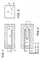
- Fig. 1 einen erfindungsgemäßen Gußkörper mit Gießform in geschnittener Seitenansicht,
- Fig. 2
wie Figur 1, gedreht um 90 Grad aus der Zeichenebene als Seitenansicht, - Fig. 3
wie Figur 1, jedoch in geschnittener Draufsicht.
- 1 a casting body according to the invention with casting mold in a sectional side view,
- 2 like Figure 1, rotated 90 degrees from the plane of the drawing as a side view,
- Fig. 3 as Figure 1, but in a sectional plan view.
Gemäß den Figuren 1 bis 3 besitzt die Gießform (1) einen Hohlraum (2), in dem sich nach dem Gießvorgang und der Erstarrung des Gießmaterials, z. B. Stahlguß der Gußkörper (3) bildet. Vor Beginn des Gießvorganges werden in den Hohlraum (2) durchströmte Hohlkörper in Form eines Rohrsystems (4) eingelegt und an geeigneter Stelle mit Einlauf (5) und Auslauf (6) durch die Wandung der Gießform (1) geführt. Während des Gießvorganges wird das Rohrsystem (4) zur Verhinderung eines vorzeitigen Aufschmelzens und zur Erreichung gleichmäßiger Abkühlbedingungen sowie gewünschter Materialeigenschaften von Kühlmittel (7, 8) durchströmt, wobei es sich um unterschiedliche Medien handeln kann (beispielsweise Wasser, Öl, Emulsionen, flüssiger Stickstoff etc.), deren Zufuhrleitungen umschaltbar ausgebildet sind. Das Rohrsystem (4) wird während oder nach der Erstarrung des Gußkörpers (3) entfernt. Zur Entfernung des Rohrsystems (4) wird dieses geschmolzen und die Schmelze des Rohrwerkstoffes z.B. mittels Druckluft ausgetrieben oder auf chemischem Wege aufgelöst und entfernt. Das im Gußkörper (3) befindliche und später zu entfernende Rohrsystem (4) besteht dabei zweckmäßigerweise aus einem niedriger als der Gußkörper (3) schmelzenden Material. Zum Beispiel können bei Stahlguß für die Kühlrohre Kupfer und bei Kupferguß Aluminium verwendet werden. Nach abgeschlossener Behandlung besteht der Gußkörper (3) bei seiner bestimmungsgemäßen Verwendung aus nur einem homogenen Material, wobei die Außenabmessungen des Rohrsystems (4) die Innenabmessungen der Kanäle bilden.According to Figures 1 to 3, the mold (1) has a cavity (2) in which after the casting process and the solidification of the casting material, for. B. cast steel forms the cast body (3). Before the start of the casting process, hollow bodies in the form of a pipe system (4) with flow through them are inserted into the cavity (2) and guided through the wall of the casting mold (1) at a suitable point with inlet (5) and outlet (6). During the casting process, the pipe system (4) is flowed through by coolant (7, 8) to prevent premature melting and to achieve uniform cooling conditions as well as the desired material properties, which can be different media (e.g. water, oil, emulsions, liquid nitrogen etc .), The feed lines are designed switchable. The pipe system (4) is removed during or after the solidification of the cast body (3). To remove the pipe system (4), it is melted and the melt of the pipe material is expelled, for example by means of compressed air, or dissolved and removed by chemical means. The pipe system (4) located in the cast body (3) and later to be removed advantageously consists of a material that melts lower than the cast body (3). For example, copper can be used for the cooling pipes for cast steel and aluminum for cast copper. After the treatment has been completed, the cast body (3), when used as intended, consists of only one homogeneous material, the external dimensions of the pipe system (4) being the same Form the internal dimensions of the channels.
Die erfindungsgemäßen Maßnahmen sind nicht auf das in den Zeichnungsfiguren dargestellte Ausführungsbeispiel beschränkt. So können beispielsweise, ohne den Rahmen der Erfindung zu verlassen, die Leitungen des Rohrsystems beliebige Querschnitte aufweisen, in beliebiger Weise geformt sein und auch mehrschichtig übereinander liegen. Die jeweilige konstruktive Ausgestaltung ist in Anpassung an die spätere Verwendung des Gußkörpers dem Fachmann anheimgestellt.The measures according to the invention are not limited to the exemplary embodiment shown in the drawing figures. For example, without departing from the scope of the invention, the lines of the pipe system can have any cross-sections, can be shaped in any way and can also lie on top of one another in multiple layers. The respective structural design is left to the person skilled in the art in adaptation to the later use of the cast body.
Claims (16)
dadurch gekennzeichnet, daß zur Entfernung des Rohrsystems dieses geschmolzen und die Schmelze mittels eines druckbeaufschlagten Mediums, vorzugsweise Druckluft ausgetrieben wird.3. The method according to claim 1 or 2,
characterized in that to remove the pipe system this is melted and the melt is expelled by means of a pressurized medium, preferably compressed air.
Applications Claiming Priority (2)
| Application Number | Priority Date | Filing Date | Title |
|---|---|---|---|
| DE3640393 | 1986-11-26 | ||
| DE19863640393 DE3640393A1 (en) | 1986-11-26 | 1986-11-26 | METHOD FOR FORMING CHANNELS IN CASTING BODIES FOR THE TRANSFER OF MEDIA FOR TEMPERATURE INFLUENCING AND CASTING BODY FOR USE AS A COMPONENT OR TOOL TO BE TEMPERATURED |
Publications (2)
| Publication Number | Publication Date |
|---|---|
| EP0268909A2 true EP0268909A2 (en) | 1988-06-01 |
| EP0268909A3 EP0268909A3 (en) | 1989-10-11 |
Family
ID=6314809
Family Applications (1)
| Application Number | Title | Priority Date | Filing Date |
|---|---|---|---|
| EP87116455A Withdrawn EP0268909A3 (en) | 1986-11-26 | 1987-11-07 | Process for manufacturing channels in cast pieces for conducting temperature-influencing mediums, and cast pieces for use as a temperature-controlled component or tool |
Country Status (2)
| Country | Link |
|---|---|
| EP (1) | EP0268909A3 (en) |
| DE (1) | DE3640393A1 (en) |
Cited By (1)
| Publication number | Priority date | Publication date | Assignee | Title |
|---|---|---|---|---|
| US5615625A (en) * | 1993-04-05 | 1997-04-01 | First National Bank Of Southern Africa Limited | System for the secure transportation of articles |
Families Citing this family (5)
| Publication number | Priority date | Publication date | Assignee | Title |
|---|---|---|---|---|
| DE19751473A1 (en) * | 1996-12-03 | 1998-06-04 | Volkswagen Ag | Die-casting machine metal die repair |
| DE19751472A1 (en) * | 1996-12-03 | 1998-06-04 | Volkswagen Ag | Pressure diecasting method and equipment |
| DE19718725A1 (en) * | 1997-05-02 | 1998-11-05 | Schmidt & Co Gmbh Kranz | Method for producing at least partially hollow metal components |
| CN102240793A (en) * | 2010-05-12 | 2011-11-16 | 南通超达机械科技有限公司 | Process for manufacturing cooling water pipe of automobile interior trim part steel casting mould |
| DE102011076312A1 (en) * | 2011-05-23 | 2012-11-29 | Robert Bosch Gmbh | Cooling device useful for housing, comprises a block of power electronics with a cooling structure to be encapsulated, which is supported by medium acting upon cooling structure to be encapsulated, and constitutes cooling surface of housing |
Citations (4)
| Publication number | Priority date | Publication date | Assignee | Title |
|---|---|---|---|---|
| US2362875A (en) * | 1943-06-03 | 1944-11-14 | Austenal Lab Inc | Casting procedure |
| US3692892A (en) * | 1969-02-24 | 1972-09-19 | Jerome H Lemelson | Casting and molding method |
| GB1386645A (en) * | 1971-10-11 | 1975-03-12 | Outokumpu Oy | Method of casting cooling elements |
| JPS603960A (en) * | 1983-06-21 | 1985-01-10 | Akita:Kk | Production of castings incorporating cooling water passage |
-
1986
- 1986-11-26 DE DE19863640393 patent/DE3640393A1/en not_active Withdrawn
-
1987
- 1987-11-07 EP EP87116455A patent/EP0268909A3/en not_active Withdrawn
Patent Citations (4)
| Publication number | Priority date | Publication date | Assignee | Title |
|---|---|---|---|---|
| US2362875A (en) * | 1943-06-03 | 1944-11-14 | Austenal Lab Inc | Casting procedure |
| US3692892A (en) * | 1969-02-24 | 1972-09-19 | Jerome H Lemelson | Casting and molding method |
| GB1386645A (en) * | 1971-10-11 | 1975-03-12 | Outokumpu Oy | Method of casting cooling elements |
| JPS603960A (en) * | 1983-06-21 | 1985-01-10 | Akita:Kk | Production of castings incorporating cooling water passage |
Non-Patent Citations (1)
| Title |
|---|
| PATENT ABSTRACTS OF JAPAN, band 9, Nr. 117 (M-381)[1840], 22. Mai 1985; & JP-A-60 003 960 (AKITA K.K.) 10-01-1985 * |
Cited By (1)
| Publication number | Priority date | Publication date | Assignee | Title |
|---|---|---|---|---|
| US5615625A (en) * | 1993-04-05 | 1997-04-01 | First National Bank Of Southern Africa Limited | System for the secure transportation of articles |
Also Published As
| Publication number | Publication date |
|---|---|
| EP0268909A3 (en) | 1989-10-11 |
| DE3640393A1 (en) | 1988-06-09 |
Similar Documents
| Publication | Publication Date | Title |
|---|---|---|
| DE2925967C2 (en) | Method of manufacturing a tubular heat exchanger | |
| DE2734388C2 (en) | Method and device for continuous casting | |
| DE19649363C2 (en) | Device and method for producing a piston unit for an internal combustion engine | |
| DE844806C (en) | Method and device for the production of composite metal bars | |
| DE2211645B2 (en) | DEVICE FOR COOLING THE DIE OF AN EXTRUSION PRESS | |
| EP0110234A1 (en) | Casting with a moulded channel | |
| EP1100640B1 (en) | Casting system for thixoforms | |
| EP0268909A2 (en) | Process for manufacturing channels in cast pieces for conducting temperature-influencing mediums, and cast pieces for use as a temperature-controlled component or tool | |
| DE3044575C2 (en) | Process and continuous casting mold for continuous horizontal continuous casting | |
| EP0158898B1 (en) | Equipment for continuous casting, and method for its manufacture | |
| EP0472546B1 (en) | Process for manufacturing plated hollow blocks | |
| DD284175A5 (en) | METHOD FOR COOLING A METALLIC SUBJECT DURING CONTINUOUS CASTING | |
| DE102005030814B4 (en) | Casting mold for metal casting | |
| DE1521195B2 (en) | Method and device for continuously casting around a metal strand with a thick layer of a metal with a lower melting point | |
| DE3812740C2 (en) | ||
| DE2945577A1 (en) | MOLD FOR CONTINUOUS CONTINUOUS | |
| DE2300528A1 (en) | COMPOSITE METAL PIPE, IN PARTICULAR PIPE BLANK, AND PROCESS FOR ITS MANUFACTURING | |
| DE19751472A1 (en) | Pressure diecasting method and equipment | |
| EP1204516A1 (en) | Method for producing a hollow body using the lost core technology | |
| DE10347947B4 (en) | Industrial furnace and associated nozzle element | |
| WO1999016564A1 (en) | Mould pipe for a continuous casting mould for the continuous casting of steels, especially peritectic steels | |
| DE3048874C2 (en) | Process for the production of thin sheet metal or strip from copper or a copper alloy | |
| EP0125509A1 (en) | One-piece continuous casting mould and method of manufacturing it | |
| DE19710887C2 (en) | Use of a mold for the production of bars from light metal or a light metal alloy, in particular from magnesium or a magnesium alloy | |
| DE102019002306A1 (en) | Water jacket casting tool for shaping a water jacket and method for shaping a water jacket |
Legal Events
| Date | Code | Title | Description |
|---|---|---|---|
| PUAI | Public reference made under article 153(3) epc to a published international application that has entered the european phase |
Free format text: ORIGINAL CODE: 0009012 |
|
| 17P | Request for examination filed |
Effective date: 19871130 |
|
| AK | Designated contracting states |
Kind code of ref document: A2 Designated state(s): AT BE CH DE ES FR GB GR IT LI LU NL SE |
|
| PUAL | Search report despatched |
Free format text: ORIGINAL CODE: 0009013 |
|
| AK | Designated contracting states |
Kind code of ref document: A3 Designated state(s): AT BE CH DE ES FR GB GR IT LI LU NL SE |
|
| 17Q | First examination report despatched |
Effective date: 19900813 |
|
| STAA | Information on the status of an ep patent application or granted ep patent |
Free format text: STATUS: THE APPLICATION IS DEEMED TO BE WITHDRAWN |
|
| 18D | Application deemed to be withdrawn |
Effective date: 19910423 |
|
| RIN1 | Information on inventor provided before grant (corrected) |
Inventor name: PLOCIENNIK, UWE Inventor name: GRONERT, DETLEF Inventor name: ALBEDYHL, MANFRED Inventor name: HILGENSTOCK, HANS |