EP0268304A2 - Machines and method for web processing by longitudinal compression - Google Patents
Machines and method for web processing by longitudinal compression Download PDFInfo
- Publication number
- EP0268304A2 EP0268304A2 EP87117160A EP87117160A EP0268304A2 EP 0268304 A2 EP0268304 A2 EP 0268304A2 EP 87117160 A EP87117160 A EP 87117160A EP 87117160 A EP87117160 A EP 87117160A EP 0268304 A2 EP0268304 A2 EP 0268304A2
- Authority
- EP
- European Patent Office
- Prior art keywords
- web
- machine
- fingers
- driving
- regions
- Prior art date
- Legal status (The legal status is an assumption and is not a legal conclusion. Google has not performed a legal analysis and makes no representation as to the accuracy of the status listed.)
- Withdrawn
Links
Images


Classifications
-
- C—CHEMISTRY; METALLURGY
- C10—PETROLEUM, GAS OR COKE INDUSTRIES; TECHNICAL GASES CONTAINING CARBON MONOXIDE; FUELS; LUBRICANTS; PEAT
- C10M—LUBRICATING COMPOSITIONS; USE OF CHEMICAL SUBSTANCES EITHER ALONE OR AS LUBRICATING INGREDIENTS IN A LUBRICATING COMPOSITION
- C10M171/00—Lubricating compositions characterised by purely physical criteria, e.g. containing as base-material, thickener or additive, ingredients which are characterised exclusively by their numerically specified physical properties, i.e. containing ingredients which are physically well-defined but for which the chemical nature is either unspecified or only very vaguely indicated
- C10M171/008—Lubricant compositions compatible with refrigerants
-
- B—PERFORMING OPERATIONS; TRANSPORTING
- B31—MAKING ARTICLES OF PAPER, CARDBOARD OR MATERIAL WORKED IN A MANNER ANALOGOUS TO PAPER; WORKING PAPER, CARDBOARD OR MATERIAL WORKED IN A MANNER ANALOGOUS TO PAPER
- B31F—MECHANICAL WORKING OR DEFORMATION OF PAPER, CARDBOARD OR MATERIAL WORKED IN A MANNER ANALOGOUS TO PAPER
- B31F1/00—Mechanical deformation without removing material, e.g. in combination with laminating
- B31F1/12—Crêping
Landscapes
- Chemical & Material Sciences (AREA)
- Chemical Kinetics & Catalysis (AREA)
- General Chemical & Material Sciences (AREA)
- Oil, Petroleum & Natural Gas (AREA)
- Organic Chemistry (AREA)
- Engineering & Computer Science (AREA)
- Mechanical Engineering (AREA)
- Treatment Of Fiber Materials (AREA)
- Preliminary Treatment Of Fibers (AREA)
- Press Drives And Press Lines (AREA)
- Basic Packing Technique (AREA)
- Auxiliary Devices For And Details Of Packaging Control (AREA)
Abstract
Description
- This invention relates to a web processing of the kind in which the web is longitudinally compressed by driving the web at a nip line formed by pairs of spaced-apart, matched rotating disks and retarding the web by devices inserted in the groove spaces between the disks.
- Devices of such a disk type were suggested more than fifty years ago for making creped products which has more or less irregular, striped form. In Campbell U.S. 1,764,676, pairs of fingers, mounted upstream of the rolls, were shown to protrude into the grooves between the driving disks. The web driven between these fingers was said to fold upon itself alternately in opposite directions from a point of contact with one finger to that with another, and to subsequently pack into the space between the fingers before exiting from the machine. According to that patent, the fingers yielding moved or oscillated between a convergent relationship and a relationship in which the fingers were substantially parallell.
- It is not known whether such a machine was ever employed commercially. In recent decades different disk drive approaches for logitudinally compressing a web have been used. Walton, U.S. Patent 2,915,109, and Packard, U.S. Patent 4,090,385, show longitudinally compacting a web by feeding it over a roll that has alternating, circumferential ribs and grooves along its length. A flat shoe presses the web against the roll to enable the ribs of the roll to drive the web forward. Then a cylindrical comb (rotating with a peripheral speed lower than the roll) or a fixed comb (whose teeth mate with the grooves of the main roll) lifts the web from the main roll and at the same time compacts it longitudinally. In the latter case, a wide, flexible metal sheet extension from the shoe engages the face of the web opposite the web face that engages the retarder comb, to form with the retarder comb a confining passage for the microcreped material. See also Walton U.S. patent 3,260,778.
- Painter, U.S. Patent 3,390,218, shows pleating a web using one smooth roll and a second smaller diameter roll having alternating ridges and grooves. A third slower moving smooth retarder roll is held against the first smooth roll in a converging relationship to force the web back toward the nip, to cause pleating. In one example of this machine, a finger member, mounted upstream of the grooved roll, protrudes into the grooves to form one side of the longitudinal compression zone at the nip, preceeding the third roll.
- In Cannard, U.S. Patent 1,680,203, a web is shown being creped by passing it into the nip between two drive rolls each having disks alternating with spacer elements. After passing through a relatively long confining passage, the web is engaged by slower rotating rolls which cause the web to crowd together to form the crepes in the long passage. The long passage is bounded by two sets of long, thin presser members, the forward ends of which are tapered and disposed in the spaces between the disks of the drive roll.
- In a different type of machine that drives the web by a nip formed by two smooth rolls, two wide, curved blades mounted downstream in opposition to the nip have provided a retarding passage which the web is forced and caused to compact, Walton et al., U.S. Patent 4,142,278.
- The invention features a machine and method for longitudinally compressing a web under the influence of driving forces provided at a nip line defined by spaced-apart pairs of matched rotating disks and under the influence of retarding forces provided by sets of retarding fingers inserted in the spaces between the disks. An important feature of the invention is that, in the region close to the nip line, web-contacting surfaces of the sets of fingers diverge in the direction of travel of the web whereby the longitudinally compressed web is subjected to tightest constraint of its thickness at a point longitudinally close to the nip line, and downstream therefrom, while still confined, the corresponding sections of web are released from tightest constraint, such diverging surfaces promoting uniform movement of the corresponding oncoming sections of compressed web while enabling relatively steady retarding forces to be transmitted laterally through the web to retard the adjacent sections of the web that are in line with the disks, whereby the longitudinal compressive treatment of both the sections of the web in line with the fingers and the sections in line with the disks can be substantially regular.
- Preferred embodiments of the invention include the following features. At least one and preferably both of the opposed surfaces of sets of fingers are convexly curved in the region close to the nip line. The radius of curvature of each of the convexly curved fingers is of the order of the radium of the disk alongside which it lies; fingers of at least one set are structurally supported from a point downstream of the nip, the fingers protruding upstream therefrom, with their tips disposed entirely within the respective spaces, below the path of travel of the web. Fingers of both sets are mounted in the manner just described. Beginning at a region spaced downstream substantially from the nip line at which region the space between the fingers has widened so that at least a major portion of face-wise pressure upon the treated web has been relieved, there is defined an elongated dwell cavity in which surfaces engaging the web become substantially parallel.
- According to another apsect, the invention features a machine and method that employs two side-by-side rolls rotating respectively in opposite directions about two spaced apart axes; each roll has larger diameter and smaller diameter segments along its length, and the larger and smaller diameter segments of the two rolls are matched to form a series of relatively shallow driving nips along a nip line, alternating with relatively deep non-driving spaces; the larger diameter segments impose face-to-face compressive forces and longitudinal driving forces on the corresponding regions of the web which pass through the nips; the non-directly driven web regions are driving indirectly by the larger diameter roll segments acting via forces transmitted through the substance of the web from the directly driven web regions to the non-directly driven web regions; a closely disposed retarding means in the form of pairs of generally divergent fingers slidably engaging the web are located to apply longitudinal retarding forces (opposite to the driving forces) on both faces of the non-directly driven regions immediately as they emerge from the nip line to produce immediate, ontinual shortening of the emerging web, the shortened web thereafter being subject to a zone of less constraint, the non-driving spaces adjacent the web permitting reorientation of the non-directly driven web regions during the shortening with less face-to-face compression than for the driven web regions; and the driven web regions being retarded indirectly by the closely disposed divergent fingers acting via forces transmitted through the substance of the web from the non-directly driven web portions, to cause the driven web regions to undergo their immediate, regular longitudinal shortening.
- Preferred embodiments of the invention also include the following features. Each larger diameter segment has a peripheral driving surface that is narrower in width than the width of the space between the peripheral driving surface and the peripheral driving surface of the next adjacent larger diameter segment. The width of the peripheral driving surface is about one half or less than the width of the space, preferably the width of the spaces being about 0.10 inch and the width of the driving surfaces being about 0.05 inch or less. The peripheral driving surfaces bear an enhanced friction treatment, such as parallel knurling cuts or fine particle plasma coating. The peripheral driving surface of each larger diameter segment is cylindrical and is narrower axially than the full axial width of the segment, and a pair of smooth tapered shoulders is provided on opposite sides of the driving surface.
- Preferred embodiments of the invention also include the following features. The stationary finger-form retarding members are cantilevered and each has, exposed for contact with a face of one of the non-directly driven web regions, a surface having a width less than the space between the corresponding adjacent larger diameter semgments. Each finger-form members rests within one of the non-driving spaces of one roll and includes a second surface (opposite the web contacting surface) that is spaced away from the peripheral surface of the associated smaller diameter segment. On each side of the web, the finger-form members are integral upstream extensions of a continuous retarder element which extends across the width of the web; the finger-form members of each element are interdigitated in the non-driving spaces of the respective roll, and the contact surfaces of the two elements are separated by a space, during operation, to permit the passage of the non-directly driven portion of the web. In some embodiments, downstream portions of the slidable contact retarder means define pathways for passage of the non-directly driven web regions that, after the initial divergence, remain shallow so that the contacting means maintains a degree of face-to-face compression upon the reorientated and compacted non-directly driven web regions as they pass via the pathways. In other embodiments, the divergence continues until the pathways are wide enough to minimize the face-to-face compressive forces applied to the non-directly driven web regions. The retarding means define short compaction cavities very close to the nip in which substantially all reorientation and compaction of the non-directly driven web regions can occur. During operation, the retarder fingers are held at substantially fixed distances from the plane on which the roll axes lie and remain steady during operation. The retarders are relatively rigid in the direction perpendicular to the faces of the web. In some embodiments, the retarding fingers terminate in flat ends; in other embodiments, in tapered or rounded ends. In important embodiments, the retarders are both supported from the downstream side.
- Preferred embodiments of the invention also have the following aspects. A dwell cavity having a pair of cavity faces is located at the outfeed side of the nip beyond the restriction and divergent passage provided by the fingers. The faces are subjected to a temperature differential along the length of the dwell cavity, with higher temperatures nearer the nip; the faces are maintained at a uniform or increasing spacing, and are subjected to even or decreasing pressure along the length of the dwell cavity. One face is integral with the retarding means; the other includes a plate attached to the retarding means.
- The relative proportion of the web which is driven can be made small, thus minimizing the total area affected by face-to-face compression where such may be disadvantageous. Driving is aided by the knurling or plasma coating. The smooth shoulders adjacent the driving surfaces provide a transitional region that can avoid tearing of the web. The compaction cavity provides space for very substantial compaction and reorientation in both directions from the plane of the web. The dwell cavity can impart to the finished web a smooth, compact quality, reduce spontaneous expansion of the finished web, enhance permanence of the treatment, and permit higher speeds of treatment.
- The invention can impart useful properties to a wide variety of webs by causing substantial, uniform face-wise reorientation and longitudinal compaction along a series of parallel longitudinal web regions. The products are characterized in general in being of very regular, stripped form. Certain materials e.g. thick bats of absorbent fibers, are compacted with no folds or undulatios in the portions moving between the fingers. Knitted goods may be treated to provide a uniform, ribbed appearance, e.g. useful as thermal underwear. Thinner and denser materials are provided with highly uniform, microcrepe in the zones of the fingers, without superficial folds or crepe.
- Other advantages and features will become apparent from the following description of the preferred embodiments, and from the claims.
- We first briefly describe the drawings.
-
- Fig. 1 is a side view of elements of a web processing machine.
- Fig. 2 is a view from the infeed side of the machine.
- Fig. 3 is a diagrammatic, isometric cutaway partial view of the retarders of the machine.
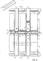
- Fig. 4 is an enlarged view from the infeed side of a representative portion of the nip of the machine.
- Fig. 5 is a diagrammatic, side elevational view taken at 5-5 in Fig. 4.
- Fig. 6 is an isometric, diagrammatic and somewhat exaggerated cutaway view of a representative portion of a web in the vicinity of the nip of the machine.
- Fig. 7 is a side sectional view showing the dwell cavity of Fig. 1.
- Figs. 8 and 9 are diagrammatic side sectional views of alternate embodiments taken at the same position as 5-5 in Fig. 4.
- Referring to Fig. 1, in
web processing apparatus 10, acontinuous web 12 is led from a supply roll (not shown) over aguide roll 14 into thenip region 15 between two drive rolls 16, 18 that are driven at the same speed in opposite directions (as indicated by the arrows). On the outfeed side, a pair ofdivergent retarders 20, 22 (one of which includes a dwell plate 21) are positioned to retard the motion ofweb 12 in a manner to be described in more detail below. The processedweb 40 is delivered to take-up roll (not shown). -
Retarders brackets respective supports support shaft rolls rod Rods retarders rods frame 37 bynots Rod 38 includes apneumatic cylinder 43 supplied by apressure line 45, which enables resilient yielding of the rod under load to provide longitudinally resilient support to retarder 22. (A feature that is used to enable self-adjustment of the retarder at start up, asweb 12 is initially compacted.). - Referring to Fig. 2, rolls 16, 18 are driven at a selected speed by a conventional motor and driving
mechanism 42 mounted onframe 37.Rolls roll disks 50. At the nip region, eachroll rolls roll 16 are opposite the lands ofroll 18 and the valleys ofroll 16 are opposite the valleys ofroll 18. - In order to guide webs of different widths into the central part of the nip, a pair of
planar plates 54, 56, the planes of which are arranged perpendicular to the role axes, are adjustably mounted on arod 58 attached to frame 46. The width of the opening betweenplates 54, 56 can then be adjusted to accommodate the width ofweb 12. Eachplate 54, 56 is thin enough to slip between adjacentlarger disks 50 to position the web such that matched lands are located at each edge of the web as it is processed. -
Rolls - Referring to Figs. 3 and 4, each of the two
retarders retarder fingers 70. Eachfinger 70 has a gently convexly curved retardingsurface 72 that slidably contacts one face of the web and anend face 73 that is substantially perpendicular to the plane of the web. The width W₄ of each finger 70 (e.g., 0.090") and the width W₅ of the space between adjacent fingers 70 (e.g., 0.060") are such thatsuccessive fingers 70 nest within successive valleys along the corresponding rolls 16, 18. Eachfinger 70 also has aback surface 75, parallel to surface 72, which, during operation, faces (but does not bear against) the peripheral surface (85 in Fig. 4) of the smaller diameter disk associated with that finger. Eachretarder bracket plate retarder brackets Fingers 70 are relatively rigid in the direction indicated byarrows 77. Dwell plate 21 (a 0.020") thick blue steel plate that is coextensive withretarder 20 in the direction of the roll axes) is welded along one of its edges to the bottom face ofretarder 20, at a distance of about 2" from the nip. The precise location ofplate 21 relative to the nip, for a given treatment of a given web, is determined by trials by moving the plate in and out until the best performance is obtained. The bottom surface ofplate 21 and the upper surface ofretarder 22 and its support define a dwell cavity whose function is described in greater detail below. - Referring to Fig. 4, each
finger 70 has a depth d₁, (e.g., 1/4") that is about two-thirds the depth d (e.g., 3/8") of the valley in which it nests. Eachlarger diameter disk 50 is machined to have a central peripheral drivingtrack 80. The total width, W, ofdisk 50 is, e.g., 0.050", the width, W₁, of thetrack 80 is between 0.025" and slightly less than 0.050" (e.g., .045"), and the total space, W₃, between tracks is between 0.100" and 0.150" (e.g., 0.110").Track 80 is cylindrical, its surface is parallel toshafts 32, 34 (Fig. 2), and it bears a rigid friction surface formed either ofparallel knurling 82 spaced at intervals of, e.g., 80 lines per inch, or by plasma coating of very fine abrasive particles, e.g. of tungsten carbide. The friction surface is chosen to enhance the drive capability of the nip while still accurately maintaining the geometry of the nip, which forms the leading side of the treatment cavity, and permitting the driven portions of the web to slide upon the roll surface when it is shortened in the treatment cavity. On either side oftrack 80 is a smoothconvex shoulder side surface 87 of thelarger diameter disk 50. Corresponding lands of the matched rolls 16, 18 (Figs. 1, 2) thus form (a) a series of relatively shallow driving nips 88 along nip line NL, in which theweb 12 is pinched (compressed by face-wise forces) and driven by longitudinal forces toward the outfeed side, and (b) an intervening series of relatively deepnon-driving spaces 92 between successive driving nips.Non-driving spaces 92 provide space on both sides ofweb 12 for its reorientation and compaction. Thedivergent retarders non-driving spaces 92 and resist the motion ofweb 12. - Referring to Fig. 5 (which does not show the preferred dwell plate), the processing of
web 12 occurs in ashort length region 90 beginning approximately at the nip region of the two rolls (at the line of centers between the axes ofroll shafts 32, 34) and ending at a point a short distance (i.e., a distance far shorter than the radius of either of therolls 16, 18) on the outfeed side slightly beyond the point of initial contact of the web with the divergent retarding fingers. The processing is accomplished by the driving forces applied at the driving nips and the interdigitated retarding forces applied at the non-driving spaces, combined with the configurations of the driving nips, the non-driving spaces, and the divergent retarders, and the positioning of the retarders relative to the rolls. Because of the divergent character of the retarding surfaces, the closest restriction presented to the oncoming web and the maximum frictional drag is near the beginning of the treatment region while portions of the treated web downstream from there are subjected to less drag. The oncoming web undergoes its longitudinal compression thickening and shortening at the beginning of the region where the aggregate retarding force is greatest and the drag of the remaining part of the channel tends to buffer the progressive flow of the compressed web with decreasing force as the web progresses, this assures even progress of the web. Such stability of the rate of progress of the treated web translates to a stable condition also at the point of initial treatment so that the entire compressive treatment of the non-driven sections of the web can be very regular. By virtue of such buffering, the retarding forces transmitted laterally through the thickness of the web to the driven sections of the web aligned with the disks are also uniformly maintained, so that regular treatment of these sections also occurs. - The precise position of the retarding fingers within each
non-driving space 92 in the nip region will depend on the thickness of the web being processed and on the fineness of the microcreping desired. A thicker web will require a greater space between the opposed fingers and a smaller space will produce a finer microtape. The best position is determined by trials at different settings for a given web and desired treatment. Prior to feeding the leading edge of the web into the nip region, the spacing between the opposing contact faces of the retarder fingers may be temporarily reduced. That spacing can be opened up to its normal running size (which is larger than the nip) by driving the web into the nip region in which case the compacting web itself will force the fingers apart against the resilient opposition provided by the pneumatic cylinder 43 (Fig. 1). Also when operation is first begun, the spacing between the roll axes must be adjusted (bynuts - Referring to Figs. 4, 5, 6, in operation,
web 12 is driven forward through the nip region toward the outfeed side along a series of narrow parallel strips (driven portions) 100. Asweb 12 reaches the nip region, the web is compressed facewise (perpendicular to the plane of the web) alongstrips 100 within driving nips 88. The friction surfaces (e.g. knurling 82) of thetracks 80 grip the compressed strips and drive them toward the outfeed side,arrows 104, Figs. 5 and 6. At the same time the non-driven regions of the web that enter the non-driving spaces are free to remain relatively less compressed facewise (in the direction perpendicularly to the web) because of the space available in the non-driving channels above and below the web. When the web reaches the retardingfingers 70, the drivenstrips 100 continue to be driven forward, by the driving force (arrows 104) but thenon-driven regions 101 receive retarding forces (arrows 102) in the opposite direction to the driving forces. As mentioned above,forces 102 are imposed by virtue of the relationship of the surfaces of the retarding fingers to the corresponding face of the web. In thetransition regions 106 between the drivenstrips 100 and thenon-driven regions 101, the web transmits at least part of the driving forces indirectly to the non-driven regions which causes reorientation and compaction of the non-driven regions within thetreatment cavities 109 that are defined by the retarding fingers. As the driving continues, the non-driving regions are compacted in the longitudinal direction of the web, and substantially reorientated. - The non-driven regions form a succession of tightly compressed undulations. Their outer portions at the faces of the webs are restrained due to frictional drag of the retarders while the inner portions are displaced forward due to the drive forces applied by the adjoining portions of the web. Thus the undulations in
regions 101 take a distorted form, which can be referred to as lazy "U's", 108, as shown in Fig. 6. The vertical space betweenretarders strips 100 propels them in succession between the retarders. - The compaction of the non-driven regions along the longitudinal direction of the web causes processed
web 40 to be relatively shorter than the unprocessed web and to exit the outfeed side at a slower rate than it is pulled into the nip region. It is found that the entire web, both the drivenstrips 100 and thenon-driven portions 101, is uniformly delivered at the outfeed side at the same rate and with the same degree of shortening. Just as thetranistion regions 106 of the web, under tension, transmit the driving forces from drivenstrips 100 to thenon-driven regions 101 to accomplish compaction ofregions 101, the transition regions, under the same tension, transmit the retardingforces 102 from thenon-driven regions 101 to the driven strips 100. As the lazy "U's" 108 are formed in the non-driven regions, compaction and microcreping of the driven strips also occurs at the outfeed end to form a series of parallel transversecompressed microcrepes 112 of lesser height which may slope in the opposite direction. - Referring to Fig. 7, as processed
web 114 proceeds away from the nip it enters a dwell cavity defined betweendwell plate 21 andretarder 22.Dwell plate 21 is attached to retarder 20 at weld line 240.Dwell plate 21 is given a slight downward curvature. This curvature is combined withadjustable weight 242, and aresilient wedge 244, to assure that the dwell cavity has a generally uniform depth M all along its length and that relatively even pressure is applied towardretarder 22 all along the length of the dwell cavity. During operation some of the heat generated inrolls retarder 22 andplate 21 so that at their ends near the nip region they reach a desired working temperature sufficient to maintain the fibers of the processed web somewhat plastic without permanently damaging them. The temperature within the dwell cavity decreases with distance from the nip region. This decrease in heat combined with the slight, even pressure applied betweenretarder 22 andplate 21 helps to set the processed web. As a result, the processed web that exists the dwell cavity can be smooth and compact, with a desired degree of permanence even when the machine is operated at relatively high speed. - Retarder 22 and
plate 21 may extend beyond the point wherebracket 26 is attached, to make the dwell cavity even longer, to accomodate still higher speeds and to provide a handy exit channel for the processed web. - The setting imparted by the dwell cavity minimizes the tendency of some types of processed web to expand facewise spontaneously, especially when processed at high speeds.
- The web may be thick or thin, woven or non-woven. In the case of thick, non-woven webs, the processed web is both compacted longitudinally and compressed facewise relative to the unprocessed web.
- Referring to Fig. 8, when the web is a relatively
thinner material 210, e.g. a woven or knit material, the spacing between the retarders may be reduced but still be left large enough so that the compression forces applied on the non-driven web regions are minimized consistent with the need to achieve retarding forces on those regions. Also the dwell cavity can be removed. In this way the hills and valleys formed initially in the web in the non-driven channels will remain substantially intact in the processedweb 212. Also the fingers of the retarder may be terminated in tapered faces 73" which would tend to reduce the friction and may reduce tearing of the web. The ends of the fingers may lie on the outfeed side of the nip line NL, as shown, spaces away as much, for instance, as 3/4" where the rolls have a radius of 2 inches. - Referring to Fig. 9, retarding
fingers 220 could alternatively be supported from the infeed side of the nip using a long curved supportingmember 222. - The non-driving spaces can be made even wider relatively to the driving nips to further reduce the proportion of the web that is directly driven especially where the web has sufficient widthwise strength to withstand the triangulation of forces imposed. In other cases, the non-driving spaces can be narrower than the nips, or the spacing as well as the widths of the retarders can be varied across the width, all depending upon the character of the material being treated and the effects desired. Other configurations of retarding means can be used and retarders may be mounted for linear adjustment in and out and up and down as well as angularly. The rolls can be of different diameters and driven at different speeds to achieve the same or different surface speeds at the nip. The valleys in one roll can be deeper than the valleys in the other roll. The contact surfaces of the retarder fingers can be provided with a frictional surface, e.g. for materials that are difficult to retard. The pressure on the retarder fingers can be increased to achieve greater compaction.
- The dwell cavity can be arranged so that the distance between the faces increases slightly with distance from the nip and/or so that the pressure between the faces decreases slightly with distance from the nip.
- The retarders could be thinner (e.g., 0.020" blue steel or 0.125" brass), and the widths of the lands and valleys could be altered. The fingers of the retarders could bear against the peripheral surface of the smaller diameter disks.
- One or both of
retarders fingers 70. These resilient fingers overliefingers 70 and are secure to retarders 20, 22 withscrews fingers 70 so that the tips of the resilient fingers meetupper surface 72 ofrigid fingers 70 at a slight angle, thereby preventing the web from catching on the tips. The greater curvature also gives more resiliency to the thin fingers. Alternatively, one or both ofretarders - Other embodiments are within the following claims.
Claims (33)
two side-by-side rolls rotating respectively in opposite directions about two spaced apart axes, each roll having larger diameter segments and smaller diameter segments along its length, said larger and smaller diameter segments of said two rolls being matched to form a series of relatively shallow driving nips along a nip line alternating with relatively deep non-driving spaces, said larger diameter segments imposing face-to-face compressive forces and longitudinal driving forces on the corresponding regions of said web which pass through said nips,
regions of said web which pass through said non-driving spaces being driven indirectly by said larger diameter roll segments acting via forces transmitted through the substance of the web from said directly driven web regions to said non-directly driven web regions, and
closely disposed retarding means in the form of pairs of generally divergent fingers slidably engaging the web, located to apply longitudinal retarding forces on both faces of the non-directly driven regions of said web immediately as they emerge from the nip line, said retarding forces having the opposite direction to said driving forces, and producing immediate, continual shortening of the emerging web, the shortened web thereupon subject to a zone of less constraint,
said non-driving spaces adjacent said web permitting reorientation of said non-directly driven web regions during said shortening with less face-to-face compression than the face-to-face compression applied to the driven web regions,
said driven web regions being retarded indirectly by said closely disposed, divergent fingers acting via forces tranmitted through the substance of the web from said non-directly driven web regions, to cause said driven web regions to undergo their immediate regular longitudinal shortening.
a cylindrical peripheral driving surface that is narrower in the axial direction than the full axial width of said larger diameter segment, and
a pair of tapered shoulders on opposite sides of said driving surface.
feeding said web into a nip region between two side-by-side rolls rotating respectively in opposite directions about two spaced apart axes, each roll having larger diameter segments and smaller diameter segments along its length, said larger and smaller diameter segments of said two rolls being matched to form a series of relatively shallow driving nips along a nip line alternating with relatively deep non-driving spaces,
imposing by means of said larger diameter segments face-to-face compressive faces and longitudinal driving forces on the corresponding portions of said web which pass through said nips,
driving web regions in said non-driven spaces by said larger diameter roll segments acting via forces transmitting through the substance of the web from said directly driven web regions to said non-directly driven web regions, and
applying retarding forces on both faces of the non-directly driven regions of said web immediately as they emerge from said nip line by means of a pair of generally diverging fingers slidably contacting the web, said retarding forces having the opposite direction to said driving forces and producing immediate, continual shortening of the emerging web, the shortened web thereupon subject to a zone of divergent constraint
said non-driving spaces adjacent said web permitting reorientation and compaction of said non-directly driven web regions with less face-to-face compression than the face-to-face compression applied to the driven web regions, and
said driven web regions being retarded indirectly by said closely disposed divergent retarding means acting via forces transmitted through the substance of the web from said non-directly driven web regions, to cause said driven web regions to undergo their immediate uniform longitudinal shortening.
Applications Claiming Priority (2)
| Application Number | Priority Date | Filing Date | Title |
|---|---|---|---|
| US93308786A | 1986-11-20 | 1986-11-20 | |
| US933087 | 1992-08-21 |
Publications (2)
| Publication Number | Publication Date |
|---|---|
| EP0268304A2 true EP0268304A2 (en) | 1988-05-25 |
| EP0268304A3 EP0268304A3 (en) | 1989-10-18 |
Family
ID=25463358
Family Applications (1)
| Application Number | Title | Priority Date | Filing Date |
|---|---|---|---|
| EP87117160A Withdrawn EP0268304A3 (en) | 1986-11-20 | 1987-11-20 | Machines and method for web processing by longitudinal compression |
Country Status (4)
| Country | Link |
|---|---|
| EP (1) | EP0268304A3 (en) |
| JP (1) | JPS63211362A (en) |
| FI (1) | FI875121A (en) |
| NO (1) | NO874838L (en) |
Cited By (1)
| Publication number | Priority date | Publication date | Assignee | Title |
|---|---|---|---|---|
| EP0347875A2 (en) * | 1988-06-24 | 1989-12-27 | Walton, Richard Rhodes | Web processing with two mated rolls |
Citations (7)
| Publication number | Priority date | Publication date | Assignee | Title |
|---|---|---|---|---|
| DE127110C (en) * | ||||
| DE130463C (en) * | ||||
| US1601633A (en) * | 1925-07-31 | 1926-09-28 | Otaka Fabric Company | Paper-crinkling machine |
| US1751471A (en) * | 1929-05-04 | 1930-03-25 | Hudson Sharp Machine Co | Creping mechanism |
| US1764676A (en) * | 1924-12-20 | 1930-06-17 | Samuel J Campbell | Creping machine |
| US2409997A (en) * | 1944-11-24 | 1946-10-22 | James W Straubel | Creping machine |
| DE846061C (en) * | 1942-08-07 | 1952-08-07 | Waldhof Zellstoff Fab | Device and method for creping paper or the like. |
-
1987
- 1987-11-19 NO NO874838A patent/NO874838L/en unknown
- 1987-11-19 FI FI875121A patent/FI875121A/en not_active Application Discontinuation
- 1987-11-20 JP JP62293862A patent/JPS63211362A/en active Pending
- 1987-11-20 EP EP87117160A patent/EP0268304A3/en not_active Withdrawn
Patent Citations (7)
| Publication number | Priority date | Publication date | Assignee | Title |
|---|---|---|---|---|
| DE127110C (en) * | ||||
| DE130463C (en) * | ||||
| US1764676A (en) * | 1924-12-20 | 1930-06-17 | Samuel J Campbell | Creping machine |
| US1601633A (en) * | 1925-07-31 | 1926-09-28 | Otaka Fabric Company | Paper-crinkling machine |
| US1751471A (en) * | 1929-05-04 | 1930-03-25 | Hudson Sharp Machine Co | Creping mechanism |
| DE846061C (en) * | 1942-08-07 | 1952-08-07 | Waldhof Zellstoff Fab | Device and method for creping paper or the like. |
| US2409997A (en) * | 1944-11-24 | 1946-10-22 | James W Straubel | Creping machine |
Cited By (2)
| Publication number | Priority date | Publication date | Assignee | Title |
|---|---|---|---|---|
| EP0347875A2 (en) * | 1988-06-24 | 1989-12-27 | Walton, Richard Rhodes | Web processing with two mated rolls |
| EP0347875A3 (en) * | 1988-06-24 | 1990-03-28 | Walton, Richard Rhodes | Web processing with two mated rolls |
Also Published As
| Publication number | Publication date |
|---|---|
| JPS63211362A (en) | 1988-09-02 |
| EP0268304A3 (en) | 1989-10-18 |
| FI875121A (en) | 1988-05-21 |
| NO874838D0 (en) | 1987-11-19 |
| NO874838L (en) | 1988-05-24 |
| FI875121A0 (en) | 1987-11-19 |
Similar Documents
| Publication | Publication Date | Title |
|---|---|---|
| US4859169A (en) | Web processing by longitudinal compression using matched drive disks and retarding fingers | |
| US4921643A (en) | Web processing with two mated rolls | |
| US3260778A (en) | Treatment of materials | |
| US4142278A (en) | Compressive treatment of web materials | |
| US5060349A (en) | Compressive treatment of webs | |
| EP0551327B1 (en) | Longitudinal compressive treatment of web materials | |
| EP0456281A2 (en) | Dynamic mechanical bonding method and apparatus | |
| US4432927A (en) | Creping machine and method | |
| US4289725A (en) | Material web for the manufacture of filter rods for tobacco products and apparatus and process for producing such web | |
| US3390218A (en) | Method of pleating sheet materials | |
| US3257253A (en) | Laminated cellular panel | |
| EP0144526B1 (en) | Method and apparatus for the compressive treatment of fabric | |
| US3188372A (en) | Machine and method for compacting materials | |
| EP0268304A2 (en) | Machines and method for web processing by longitudinal compression | |
| US6134758A (en) | Method of producing improved crimped polyester fibers | |
| CA1167627A (en) | Longitudinal compressive treatment method and apparatus for web materials | |
| WO1996017991A1 (en) | Means for controlling deflection in a two-roll fabric shrinker | |
| GB2116593A (en) | Microcreping with surface diversion retarding | |
| US4432926A (en) | Method and apparatus for imparting two-way properties to flexible webs | |
| FI73625C (en) | ANORDINATION OVER FOERFARANDE FOER MIKROKRAEPPNING AV EN BANA. | |
| CA1260748A (en) | Longitudinal compressive treatment of webs | |
| CH220172A (en) | Bottle swing top with valve. |
Legal Events
| Date | Code | Title | Description |
|---|---|---|---|
| PUAI | Public reference made under article 153(3) epc to a published international application that has entered the european phase |
Free format text: ORIGINAL CODE: 0009012 |
|
| AK | Designated contracting states |
Kind code of ref document: A2 Designated state(s): AT BE CH DE FR GB IT LI NL SE |
|
| PUAL | Search report despatched |
Free format text: ORIGINAL CODE: 0009013 |
|
| AK | Designated contracting states |
Kind code of ref document: A3 Designated state(s): AT BE CH DE FR GB IT LI NL SE |
|
| 17P | Request for examination filed |
Effective date: 19900417 |
|
| 17Q | First examination report despatched |
Effective date: 19910311 |
|
| STAA | Information on the status of an ep patent application or granted ep patent |
Free format text: STATUS: THE APPLICATION IS DEEMED TO BE WITHDRAWN |
|
| 18D | Application deemed to be withdrawn |
Effective date: 19931005 |