EP0268108A1 - Hand-held instrument for implanting, dispensing, and inflating an inflatable membrane - Google Patents
Hand-held instrument for implanting, dispensing, and inflating an inflatable membraneInfo
- Publication number
- EP0268108A1 EP0268108A1 EP87115608A EP87115608A EP0268108A1 EP 0268108 A1 EP0268108 A1 EP 0268108A1 EP 87115608 A EP87115608 A EP 87115608A EP 87115608 A EP87115608 A EP 87115608A EP 0268108 A1 EP0268108 A1 EP 0268108A1
- Authority
- EP
- European Patent Office
- Prior art keywords
- membrane
- instrument
- patient
- trocar
- infusion tube
- Prior art date
- Legal status (The legal status is an assumption and is not a legal conclusion. Google has not performed a legal analysis and makes no representation as to the accuracy of the status listed.)
- Ceased
Links
Images


Classifications
-
- A—HUMAN NECESSITIES
- A61—MEDICAL OR VETERINARY SCIENCE; HYGIENE
- A61B—DIAGNOSIS; SURGERY; IDENTIFICATION
- A61B17/00—Surgical instruments, devices or methods, e.g. tourniquets
- A61B17/34—Trocars; Puncturing needles
- A61B17/3468—Trocars; Puncturing needles for implanting or removing devices, e.g. prostheses, implants, seeds, wires
-
- A—HUMAN NECESSITIES
- A61—MEDICAL OR VETERINARY SCIENCE; HYGIENE
- A61F—FILTERS IMPLANTABLE INTO BLOOD VESSELS; PROSTHESES; DEVICES PROVIDING PATENCY TO, OR PREVENTING COLLAPSING OF, TUBULAR STRUCTURES OF THE BODY, e.g. STENTS; ORTHOPAEDIC, NURSING OR CONTRACEPTIVE DEVICES; FOMENTATION; TREATMENT OR PROTECTION OF EYES OR EARS; BANDAGES, DRESSINGS OR ABSORBENT PADS; FIRST-AID KITS
- A61F2/00—Filters implantable into blood vessels; Prostheses, i.e. artificial substitutes or replacements for parts of the body; Appliances for connecting them with the body; Devices providing patency to, or preventing collapsing of, tubular structures of the body, e.g. stents
- A61F2/0004—Closure means for urethra or rectum, i.e. anti-incontinence devices or support slings against pelvic prolapse
- A61F2/0031—Closure means for urethra or rectum, i.e. anti-incontinence devices or support slings against pelvic prolapse for constricting the lumen; Support slings for the urethra
- A61F2/0036—Closure means for urethra or rectum, i.e. anti-incontinence devices or support slings against pelvic prolapse for constricting the lumen; Support slings for the urethra implantable
- A61F2/004—Closure means for urethra or rectum, i.e. anti-incontinence devices or support slings against pelvic prolapse for constricting the lumen; Support slings for the urethra implantable inflatable
-
- Y—GENERAL TAGGING OF NEW TECHNOLOGICAL DEVELOPMENTS; GENERAL TAGGING OF CROSS-SECTIONAL TECHNOLOGIES SPANNING OVER SEVERAL SECTIONS OF THE IPC; TECHNICAL SUBJECTS COVERED BY FORMER USPC CROSS-REFERENCE ART COLLECTIONS [XRACs] AND DIGESTS
- Y10—TECHNICAL SUBJECTS COVERED BY FORMER USPC
- Y10S—TECHNICAL SUBJECTS COVERED BY FORMER USPC CROSS-REFERENCE ART COLLECTIONS [XRACs] AND DIGESTS
- Y10S128/00—Surgery
- Y10S128/25—Artificial sphincters and devices for controlling urinary incontinence
Definitions
- This invention relates to a compact, hand-held instrument which enables a physician to perform a relatively quick and simple procedure to accurately and controllably implant, dispense and inflate an inflatable membrane (e.g. a genitourinary prosthesis) at a predetermined target area within the urethral tissues of a patient to enable a patient to overcome urinary incontinence by means of increasing both localized tissue volume and passive occlusive pressure proximal to the periurethral tissues of the proximal corpus spongiousum.
- an inflatable membrane e.g. a genitourinary prosthesis
- an artificial prosthetic sphincter has often been implanted so that occlusive pressure may be applied to the urethra to restore continence.
- Artificial sphincters are well-known and specific examples thereof will not be listed.
- the implantation of an artificial sphincter commonly requires a surgical procedure which necessitates the hospitalization of the patient. Such a procedure is relatively complex and expensive, and usually requires six to eight weeks or more of recovery time.
- both the patient and his physician face approximately two months of delay before being able to activate the prosthesis to ascertain whether the surgery has been successful and the patient is continent. More particularly, because of the swollen and aggravated condition of edema of the urethral tissues during and for a period subsequent to surgery, the physician cannot precisely match the occlusive pressure available from the prosthetic sphincter to the patient's urethra. Therefore, at the time of implant, the physician must estimate the required minimal occlusive pressure needed to achieve urethral coaptation in that particular patient.
- sphincteric mechanisms are often improperly fitted or selected with inaccurate pressure ranges, so that the occlusive pressures generated by such mechanisms are either insufficient to successfully achieve continence or excessive to the point of causing ischemia and subsequent necrosis and erosion of urethral tissue. Excessive occlusive forces may undesirably minimize arteriovascular blood flow to the urethra and thereby cause ischemia and subsequent erosion of the delicate tissues. What is more, if the implant surgery should prove to be unsuccessful (i.e. the maximum occlusive pressure to be generated by the sphincter is insufficient to hold the patient incontinent or the sphincter malfunctions mechanically), then additional surgery becomes necessary to provide sphincteric adjustment, repair or explant.
- a compact, hand-held instrument to enable a physician to reliably and controllably implant, dispense and inflate an inflatable membrane at a predetermined target area within the tissue of the patient.
- the disclosed instrument may be used as part of a relatively simple, non-surgical procedure by which to accurately and safely implant an inflatable genitourinary prosthesis in the periurethral tissues of the corpus spongiousum, so that a patient ma y overcome urinary continence.
- the instrument includes an associated vernier hypodermic syringe, or the like, for supplying fluid to inflate the membrane.
- the instrument also includes an assembly of telescoping trocar elements which may be placed in a retracted condition for dilating a tunnel through the urethral tissue of the patient or in an expanded condition for placing, dispensing and inflating the membrane.
- the trocar assembly comprises a pair of articulating tunneling members which enclose and protect the membrane.
- the tunneling members may be closed around the membrane in the expanded trocar condition to form a sharp cutting nose to penetrate the urethral tissue of the patient, or, the tunneling members may be angularly separated so that the membrane is exposed to the urethral tissue for implantation and inflation therewithin.
- the membrane is affixed to a hollow, non-coring needle, which needle is attached to one end of a fluid infusion tube.
- the other end of the fluid infusion tube communicates with the vernier hyopdermic syringe, so that a measured volume of fluid can be percutaneously infused from the syringe to the membrane by way of the fluid infusion tube and the needle.
- the needle and infusion tube are retracted through a coaxially arranged trocar tube, whereby the trocar tube forms a shoulder for reliably detaching an inflated membrane from the needle.
- the trocar assembly is withdrawn from the patient with the inflated membrane remaining at the targeted tissue site.
- An inflated membrane proportionately increases local tissue volume in the area of the periurethral tissues of the corpus spongiousum to correspondingly increase the occlusive pressure applied to the urethral tissues for restoring a patient to continence.
- One or more of the membranes may be implanted and inflated, depending upon etiology, degree of residual sphincteric function, vascularity and physical properties of the patient's urethral tissues.
- FIG. 1 there is shown the hand-held instrument 1 which includes a control housing 2 for supporting an assembly 4 of telescoping trocar elements at one end thereof and a suitable grip or handle 6 at the opposite end.
- a hemostat 70 is attached to and slideable along the trocar assembly 4 for attachment to the patient's skin or to a surgical drape to increase axial instrument stability.
- Extending downwardly from control housing 2 is a trigger 8.
- a support bracket 12 extends upwardly from one end of control housing 2.
- An infuser terminal 14 is connected to an inlet of a fluid transfer tube 16.
- Extending upwardly from the opposite end of control housing 2 is a hypodermic syringe receptacle 18 .
- Infuser terminal 14 and syringe receptacle 18 are aligned with one another to receive and support a vernier hypodermic syringe (shown in phantom and designated 20), such that fluid may be percutaneously infused from syringe 20 by way of transfer tube 16 to inflate the inflatable membrane according to a procedure that will be described in greater detail when referring hereinafter to FIGs. 4-13.
- a longitudinally extending tracking slot 22 is formed in control housing 2.
- a retractor knob 24 and an actuator knob 26 are received within and slideable along tracking slot 22.
- Each of the retractor knob 24 and actuator knob 26 has a respective release button 29 which must be depressed to permit the retractor and actuator knobs 24 and 26 to slide along the slot 22.
- Suitable positioning indicia is marked on control housing 2 along the length of tracking slot 22 to denote certain locations to which the retractor knob 24 and actuator knob 26 are to be moved to accurately and controllably implant, dispense, and inflate a membrane within the bodily tissues of a patient.
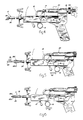
- FIGs. 2a and 2b of the drawings the assembly 4 of telescoping trocar elements is described.
- a pair of normally opened, articulating clam shell-shaped tunneling members 28-1 and 28-2 are withdrawn into the trocar assembly 4 and retained in a closed configuration around an inflatable membrane 50 to protect the membrane and provide a sharp, blunt dilating nose by which to dilate a tunnel through the patient's tissue for implanting the membrane 50.
- the clam shellshaped tunneling members 28-1 and 28-2 are released from the trocar assembly 4 so as to be automatically opened for the purpose of permitting the membrane 50 to be positioned, dispensed, and inflated at a targeted area within the patient's tissues.
- the trocar assembly 4 comprises an outer trocar sleeve 30 which functions as a nest for receiving therewithin and closing the tunneling members 28-1 and 28-2 when the assembly is retained in the retracted trocar condition of FIG. 2b.
- An inner trocar tube 32 is coaxially arranged with outer trocar sleeve 30.
- Concentrically arranged with and slideable through inner trocar tube 30 is a fluid infusion tube 34.
- Fluid infusion tube 34 supports a non-coring, hollow needle 36 at one end thereof and provides a fluid channel which is connected at the opposite end with the fluid transfer tube 16 (of FIG. 1) for delivering fluid to the membrane 50 via needle 36.
- the membrane 50 is attached to needle 36 to receive fluid supplied by the hypodermic syringe and delivered via the needle and the fluid infusion tube 34.
- fluid infusion tube 34 has a hyperbolically-radiused base section to efficiently distribute stresses and increase resistance to breakage at the point at which non-coring needle 36 is attached. In this manner, the needle 36 will be less likely to break as a consequence of mechanical forces encountered during the placing and dispensing of membrane 50.
- the coaxial arrangement of fluid infusion tube 34 and inner trocar tube 32 creates a shoulder against which membrane 50 is reliably and safely removed from the needle 36 when fluid infusion tube 34 is retracted through inner trocar tube 32 after the membrane 50 has been suitably implanted and inflated within the tissues of the patient.
- FIG. 3 of the drawings illustrates the interconnection between the fluid supply system and the assembly 4 of telescoping trocar elements of the hand-held instrument 1, so that fluid may be supplied from hypodermic syringe 20 to membrane 50 (of FIG. 2a) by wa y of fluid transfer tube 16 and fluid infusion tube 34. More particularly, a proximal end of fluid transfer tube 16 is connected to syringe 20 at infuser terminal 14. A distal end of fluid transfer tube 16 is affixed to a proximal end of fluid infusion tube 34. Also connected to the proximal end of fluid infusion tube 34 is a moveable infusion tube collar 40.
- Infusion tube collar 40 is connected to and positioned by actuator knob 26, such that a movement of actuator knob 26 through the tracking slot 22 (of FIG. 1) causes a corresponding axial movement of both infusion tube collar 40 and infusion tube 34.
- Fluid infusion tube 34 extends from the connection with fluid transfer tube 16, through the interior of control housing 2, to the non-coring needle 36 (of FIG. 2a). Therefore, the physician may controllably move the fluid infusion tube 34 and the needle 36 between the retracted trocar condition of FIG. 2b and the expanded trocar condition of FIG. 2a whenever the actuator knob 26 is moved back and forth along the tracking slot 22.
- Inner trocar tube 52 Surrounding fluid infusion tube 34 is the inner trocar tube 52.
- inner trocar tube 52 Connected to a first end of inner trocar tube 32 is a moveable inner trocar collar 42.
- Inner trocar tube collar 42 is connected to and positioned by retractor knob 24, such that a movement, by the physician, of retractor knob 24 through the tracking slot 22 (of FIG. 1) causes a corresponding axial movement of inner trocar tube 32 between the retracted trocar position of FIG. 2b and the expanded trocar position of FIG. 2a.
- retractor knob 24 Connected to a first end of inner trocar tube 32 is a moveable inner trocar collar 42.
- Inner trocar tube collar 42 is connected to and positioned by retractor knob 24, such that a movement, by the physician, of retractor knob 24 through the tracking slot 22 (of FIG. 1) causes a corresponding axial movement of inner trocar tube 32 between the retracted trocar position of FIG. 2b and the expanded trocar position of FIG. 2a.
- retractor knob 24 causes inner trocar tube 32 to be withdrawn from the expanded trocar condition and moved into the retracted trocar condition. Therefore, the physician may safely detach an inflated membrane from needle 36 by moving actuator knob 26 and thereby causing fluid infusion tube 34 and the needle 36 which is attached thereto to slide through inner trocar tube 32 towards the retracted trocar condition (of FIG. 2b).
- the second end of inner trocar tube 32 forms a shoulder for engaging and detaching the membrane from the needle 36 as the fluid infusion tube 34 is retracted through the trocar tube 32.
- outer trocar sleeve 30 Surrounding inner trocar tube 32 is the outer trocar sleeve 30. Connected to one end of outer trocar sleeve 30 is a moveable outer trocar collar 44. Outer trocar collar 44 has a hollow configuration for receiving and supporting the coaxial arrangement of inner trocar tube 32 and fluid infusion tube 34. Outer trocar collar 44 is connected to and positioned by a tracking plate 48. Tracking plate 48 is received within and slideable along a hollow track 52 which extends axially through control housing 2. Tracking plate 48 is connected by a rod 53 and a bearing 55 to an integral arm 54 of trigger 8.
- trigger 8 in either of the directions of reference arrow 56 causes the tracking plate 48 to slide along track 52 and outer trocar collar 44 to move outer trocar sleeve 30 into either the retracted trocar condition of FIG. 2b (for receiving and closing tunneling members 28-1 and 28-2 to form a tissue penetrating nose) or the expanded trocar condition of FIG. 2a (for releasing and thereby opening tunneling members 28-1 and 28-2 for permitting the inflation of a membrane).
- Opposing detents are formed at the rearward end of tunneling members 28-1 and 28-2 and the forward end of outer trocar sleeve 30.
- pulling the trigge r 8 in a rearward direction causes outer trocar sleeve 30 to be moved rearwardly towards the expanded trocar condition (of FIG. 2a) so that tunneling members 28-1 and 28-2 can be released and opened.
- the detents of sleeve 30 and tunneling members 28-1 and 28-2 will eventually engage one another to withdraw the opened tunneling members away from, and thereby expose, the non-coring needle 36 for attachment to or inflation of the membrane.
- outer trocar sleeve 30 Likewise, pushing the trigger 8 in a forward direction causes outer trocar sleeve 30 to be moved forwardly towards the retracted trocar condition (of FIG. 2b) to thereby return outer trocar sleeve 30 to a position at which to retain and close the tunneling members 28-1 and 28-2.
- Trigger return lever 10 is pivotally connected to tracking plate 48, such that lever 10 will ride along with trigger 8 whenever the trigger is moved in either of the directions indicated by reference arrow 56.
- Trigger 8 travels between forward and rearward indexing notches 64-1 and 64-2 formed in the bottom of control housing 2 to move the outer trocar sleeve 30 between the retracted and expanded trocar conditions.
- trigger 8 must first be rotated out of an indexing notch 64-1 or 64-2 (against the bias of an associated spring) before the trigger can be pulled rearwardly or returned forwardly along control housing 2.
- Trigger return lever 10 may be locked to form a stop when the trigger 8 is located at the rearward indexing notch 64-2 to prevent an inadvertent return of the trigger to the forward indexing notch 64-1 and a premature closing of tunneling members 28-1 and 28-2. That is, trigger return lever 10 must be rotated to an unlocked position (shown in phantom) in order to permit the physician to rotate trigger 8 out of the rearward indexing notch 64-1 for moving trigger 8 forwardly for the purpose of closing tunneling members 28-1 and 28-2.
- FIGs. 4-13 of the drawings The operation of the hand-held instrument 1 for implanting, dispensing and inflating the inflatable membrane 50 is described while referring to FIGs. 4-13 of the drawings.
- the retracter knob 24 and actuator knob 26 of instrument 1 are initially moved to forward positions along tracking slot 22 (designated by indicia marked A4 and A3, respectively).
- the telescoping members of trocar assembly 4 are initially in a retracted trocar condition, and tunneling members 28-1 and 28-2 are closed to form the blunt dilating cutting nose.
- the physician using sterile procedures, then fills vernier hypodermic syringe 20 with a suitable biocompatible fluid (e.g. a radio opaque isotonic fluid, isotonic saline solution, or the like).
- a suitable biocompatible fluid e.g. a radio opaque isotonic fluid, isotonic saline solution, or the like.
- a fluid in this invention is not to be regarded as a limitation, and the syringe 20 may alternatively be filled with a suspension of particulate matter, particles, and the like.
- the trigger 8 is pulled rearwardly (in the direction of reference arrow 57 of FIG. 5) to simultaneously retract outer trocar sleeve 30 and tunneling members 28-1 and 28-2 so as to expose the non-coring needle 36 of fluid infusion tube 34.
- the physician rotates a control knob 60 (best shown in FIG. 4) of syringe 20 whereby fluid is infused from the syringe to needle 36 by way of fluid transfer tube 16 and fluid infusion tube 34 to purge any trapped air from the fluidic system of the instrument 1.
- the physician affixes an uninflated membrane 50 to the needle 36 by piercing a core of membrane 50 with needle 36 and pressing the membrane onto the needle until forward movement of the needle is blocked by a concave surface of a sel f-contained metallic needle stop (not shown).
- the membrane 50 is an elastic, elliptoidally-shaped genitourinary prosthesis, such as that disclosed in U.S. Patent Application Serial No. 881,829 filed July 3, 1986.
- the prosthesis is formed from a tear-resistant, biocompatible material, such as, for example, polyurethane, silicone, latex, or the like. Accordingly, the teachings of said patent application regarding the genitourinary prosthesis membrane 50 and the receipt of needle 36 through a core and by a needle stop of membrane 50 are incorporated herein by reference.
- the physician rotates the trigger return lever 10 (in the direction of reference arrow 58) to permit trigger 8 to move forwardly for placing the trocar assembly 4 back in the retracted trocar condition, whereby tunneling members 28-1 and 28-2 are retained within outer trocar sleeve 30 and closed around the installed membrane 50.
- the instrument 1 is now ready to enable the physician to implant the membrane 50 within the bodily tissues of the patient.
- the dilating nose of instrument 1 (as formed by tunneling members 28-1 and 28-2 of trocar assembly 4) is inserted into the patient's tissue.
- Radiographic, fluoroscopic, cystoscopic, tactile or other conventional means may be used to navigate the dilating nose into position at the patient's implant target site.
- the target site is located in the periurethral tissues of the proximal corpus spongiousum of the patient at which the physician may implant and inflate the membrane 50 to thereby enable the patient to overcome urinary incontinence by means of increasing both localized tissue volume at and passive occlusive pressure of the periurethral tissues. Therefore, the physician exerts a force upon the instrument 1 sufficient to transurethrally or perineally insert the dilating nose of trocar assembly 4 to bluntly disect a small tunnel through the patient's urethral tissue 62.
- the physician once again pulls the trigger 8 in a rearward direction (in the direction of reference arrow 59) for placing the trocar assembly 4 of instrument 1 in the expanded trocar condition of FIG. 2a.
- the outer trocar sleeve 30 is withdrawn and the tunneling members 28-1 and 28-2 are released and pulled away from membrane 50 by the sleeve 30. Accordingly, the tunneling members are opened so as to expose the previously attached and uninflated membrane 50 to the patient's urethral tissue 62.
- the physician clamps the sliding hemostat 70 to the patient's skin and/or to a surgical drape (not shown) to stabilize the instrument 1 against axial movements, either proximally or distally, and permit the physician to inflate the membrane 50 at the precise designated target area within the patient's urethral tissue 62.
- the physician inflates the membrane 50 by percutaneously infusing an incrementally regulated amount of fluid (or solid matter) from the vernier hypodermic syringe 20 to the interior of the membrane 20.
- the physician detaches a deflated membrane 50 from the needle (36 in FIG. 10) and withdraws such needle and the fluid infusion tube (34 in FIG. 10) through the inner trocar tube 32.
- the physician slides actuator knob 26 out of its initial forward position (designated by indicia marked A3) to a final rearward position along tracking slot 22 (designated by indicia marked B3).
- the rearward movement of actuator knob 26 along slot 22 withdraws the fluid infusion tube 34 through inner trocar tube 32 and safely detaches the inflated membrane 50 from needle 36 against the shoulder formed by coaxially arranged trocar tube 32.
- the inflated membrane remains precisely at its position of placement within the targeted (i.e. urethral) tissues 62 of the patient.
- the physician withdraws the inner trocar tube 32 by sliding retracter knob 24 out of its initial forward position (designated by indicia marked A4) to a final rearward position along tracking slot 22 (designated by indicia marked B4).
- Inner trocar tube 32 also has detents (not shown) which engage the tunneling members 28-1 and 28-2 to simultaneously retract such members into outer trocar sleeve 30.
- the trocar assembly 4 of instrument 1 is then withdrawn from the urethral tissues 62 in FIG. 13 without disturbing the condition or position of the inflated membrane 50. Inasmuch as only a small wound remains after withdrawal of trocar assembly 4, a single skin suture placed at the center of the wound should be sufficient to close the patient's tissue.
- FIG. 14 of the drawings shows an alternate trocar assembly 4 ⁇ to be used in the instrument 1 of FIG. 1. More particularly, both the outer trocar sleeve 30 and the inner trocar tube 32 are provided with a matrix of perforations or apertures 66 through which a sterilizing liquid or gas may pass for reliably and conveniently sterilizing the telescoping members of the trocar assembly 4 ⁇ .
- sterilizing gases such as ethylene oxide or sterilizing solutions such as Cidex or betadine may be passed through the perforations 66.
- Sterilization of trocar assembly 4 ⁇ may also be accomplished in a conventional autoclave, where the perforations 66 will permit an efficient circulation of sterilizing steam between trocar sleeve 30, trocar tube 32 and infusion tube 34.
- the presently disclosed instrument has been explained with reference to implanting, dispensing and inflating a single membrane 50, it is to be expressly understood that any number of such membranes may be implanted, depending upon the increased tissue volume and resulting occlusive pressure which are required to permit a patient to be restored to continence.
- the physician may cystoscopically monitor the patient's degree of coaptation of the urethral mucosa. In the event that greater occlusive pressure is needed, the physician may implant a corresponding additional number of prostheses until patient continence is restored.
- the instrument 1 has applications other than for implanting an inflatable membrane for use as a genitourinary prosthesis to enable a patient to overcome incontinence.
- the hand-held instrument disclosed herein may also be used to implant a selectively permeable (by a gas or liquid) membrane which may function as a drug delivery system.
- Other applications include an instrument for implanting a variable volume mass to replace surgically removed tissue and/or organ excisions or an injectable antiureteral reflux mass.
- Still further applications of the present invention include an instrument for implanting a testicular prosthesis, an injectable closure blockage for arteries and veins, a prosthetic sphincter, and an injectable intraocular lens,
- the inflatable membrane described in this invention is also applicable for con trollably occluding luminal passages other than the patient's urethra when it is necessary to selectively control the flow of material therethrough.
Abstract
A compact, hand-held instrument (1) is disclosed by which to permit a physician to accurately and controllably implant, dispense, and inflate an inflatable membrane (50) at a predetermined target area within the tissues (62) of a patient. The inflatable membrane is preferably a genitourinary prosthesis, and the targeted area lies within the corpus spongiousum surrounding the urethra to enable a patient to overcome urinary incontinence by means of increasing both localized tissue volume and passive occlusive pressure upon the urethral mucosa. The instrument includes a trocar assembly having a plurality of telescoping trocar members (30, 32, 34) which may be either retracted for dilating a tunnel through the urethral tissues of the patient or expanded for placing, dispensing and inflating the membrane at the end of the tunnel. The membrane is percutaneously infused with and inflated by material (e.g. biocompatible fluid) supplied from a vernier hypodermic syringe (20) to a hollow, non-coring needle, which needle carries the membrane and communicates with the syringe.
Description
- This invention relates to a compact, hand-held instrument which enables a physician to perform a relatively quick and simple procedure to accurately and controllably implant, dispense and inflate an inflatable membrane (e.g. a genitourinary prosthesis) at a predetermined target area within the urethral tissues of a patient to enable a patient to overcome urinary incontinence by means of increasing both localized tissue volume and passive occlusive pressure proximal to the periurethral tissues of the proximal corpus spongiousum.
- As will be known to those skilled in the art, in cases where the natural sphincter muscles of a patient have been surgically excised, damaged by disease or compromised by physical trauma, an artificial prosthetic sphincter has often been implanted so that occlusive pressure may be applied to the urethra to restore continence. Artificial sphincters are well-known and specific examples thereof will not be listed. However, the implantation of an artificial sphincter commonly requires a surgical procedure which necessitates the hospitalization of the patient. Such a procedure is relatively complex and expensive, and usually requires six to eight weeks or more of recovery time. Accordingly, both the patient and his physician face approximately two months of delay before being able to activate the prosthesis to ascertain whether the surgery has been successful and the patient is continent. More particularly, because of the swollen and aggravated condition of edema of the urethral tissues during and for a period subsequent to surgery, the physician cannot precisely match the occlusive pressure available from the prosthetic sphincter to the patient's urethra. Therefore, at the time of implant, the physician must estimate the required minimal occlusive pressure needed to achieve urethral coaptation in that particular patient. As a consequence of such estimate, sphincteric mechanisms are often improperly fitted or selected with inaccurate pressure ranges, so that the occlusive pressures generated by such mechanisms are either insufficient to successfully achieve continence or excessive to the point of causing ischemia and subsequent necrosis and erosion of urethral tissue. Excessive occlusive forces may undesirably minimize arteriovascular blood flow to the urethra and thereby cause ischemia and subsequent erosion of the delicate tissues. What is more, if the implant surgery should prove to be unsuccessful (i.e. the maximum occlusive pressure to be generated by the sphincter is insufficient to hold the patient incontinent or the sphincter malfunctions mechanically), then additional surgery becomes necessary to provide sphincteric adjustment, repair or explant.
- Consequently, there is no apparatus or relatively simple, non-surgical procedure known to be available by which a physician may reliably and safely implant a genitourinary prosthesis to enable a patient to overcome urinary incontinence. While it has been suggested that urinary incontinence may be successfully treated with a periurethral injection of TEFLON paste, this treatment has been known to lead to potential problems as a result of the migration of paste particles from the injection site.
- Briefly, and in general terms, a compact, hand-held instrument is disclosed to enable a physician to reliably and controllably implant, dispense and inflate an inflatable membrane at a predetermined target area within the tissue of the patient. The disclosed instrument may be used as part of a relatively simple, non-surgical procedure by which to accurately and safely implant an inflatable genitourinary prosthesis in the periurethral tissues of the corpus spongiousum, so that a patient ma y overcome urinary continence.
- The instrument includes an associated vernier hypodermic syringe, or the like, for supplying fluid to inflate the membrane. The instrument also includes an assembly of telescoping trocar elements which may be placed in a retracted condition for dilating a tunnel through the urethral tissue of the patient or in an expanded condition for placing, dispensing and inflating the membrane. The trocar assembly comprises a pair of articulating tunneling members which enclose and protect the membrane. The tunneling members may be closed around the membrane in the expanded trocar condition to form a sharp cutting nose to penetrate the urethral tissue of the patient, or, the tunneling members may be angularly separated so that the membrane is exposed to the urethral tissue for implantation and inflation therewithin. The membrane is affixed to a hollow, non-coring needle, which needle is attached to one end of a fluid infusion tube. The other end of the fluid infusion tube communicates with the vernier hyopdermic syringe, so that a measured volume of fluid can be percutaneously infused from the syringe to the membrane by way of the fluid infusion tube and the needle. The needle and infusion tube are retracted through a coaxially arranged trocar tube, whereby the trocar tube forms a shoulder for reliably detaching an inflated membrane from the needle.
- The trocar assembly is withdrawn from the patient with the inflated membrane remaining at the targeted tissue site. An inflated membrane proportionately increases local tissue volume in the area of the periurethral tissues of the corpus spongiousum to correspondingly increase the occlusive pressure applied to the urethral tissues for restoring a patient to continence. One or more of the membranes may be implanted and inflated, depending upon etiology, degree of residual sphincteric function, vascularity and physical properties of the patient's urethral tissues.
-
- FIG. 1 shows an isometric view of the hand-held instrument which forms the present invention;
- FIG. 2a shows a telescoping trocar assembly of the instrument of FIG. 1 in an expanded trocar condition;
- FIG. 2b shows the trocar assembly of the instrument of FIG. 1 in a retracted trocar condition;
- FIG. 3 shows a partial cross-section of the instrument of FIG. 1 so as to illustrate details of the trocar assembly interconnected with an associated fluidic system;
- FIGs. 4-13 illustrate the steps for operating the present instrument for implanting, dispensing and inflating an inflatable membrane; and
- FIG. 14 shows an alternate trocar assembly including a matrix of perforations through which to pass a sterilizing liquid or gas.
- The hand-held instrument of the present invention for implanting, dispensing and inflating inflatable membranes is now described while referring to the drawings. Referring initially to FIG. 1, there is shown the hand-held instrument 1 which includes a
control housing 2 for supporting anassembly 4 of telescoping trocar elements at one end thereof and a suitable grip or handle 6 at the opposite end. A hemostat 70 is attached to and slideable along thetrocar assembly 4 for attachment to the patient's skin or to a surgical drape to increase axial instrument stability. Extending downwardly fromcontrol housing 2 is atrigger 8. Also extending downwardly from thecontrol housing 2 ahead oftrigger 8, is atrigger return lever 10. The function and operation oftrigger 8 andtrigger return lever 10 will be disclosed in greater detail when referring to FIG. 3. Asupport bracket 12 extends upwardly from one end ofcontrol housing 2. Aninfuser terminal 14 is connected to an inlet of afluid transfer tube 16. Extending upwardly from the opposite end ofcontrol housing 2 is ahypodermic syringe receptacle 18 .Infuser terminal 14 andsyringe receptacle 18 are aligned with one another to receive and support a vernier hypodermic syringe (shown in phantom and designated 20), such that fluid may be percutaneously infused fromsyringe 20 by way oftransfer tube 16 to inflate the inflatable membrane according to a procedure that will be described in greater detail when referring hereinafter to FIGs. 4-13. By way of example only, a vernier hypodermic syringe which has particular application for use with instrument 1 for supplying fluid to inflate a membrane is described in United States Patent Application Serial No. 923,572 entitled SNAP-ON VERNIER SYRINGE filed 27 October 1986. - A longitudinally extending
tracking slot 22 is formed incontrol housing 2. Aretractor knob 24 and anactuator knob 26 are received within and slideable alongtracking slot 22. Each of theretractor knob 24 andactuator knob 26 has arespective release button 29 which must be depressed to permit the retractor andactuator knobs slot 22. Suitable positioning indicia is marked oncontrol housing 2 along the length oftracking slot 22 to denote certain locations to which theretractor knob 24 andactuator knob 26 are to be moved to accurately and controllably implant, dispense, and inflate a membrane within the bodily tissues of a patient. - Referring now to FIGs. 2a and 2b of the drawings, the
assembly 4 of telescoping trocar elements is described. In a retracted trocar condition of FIG. 2b, a pair of normally opened, articulating clam shell-shaped tunneling members 28-1 and 28-2 are withdrawn into thetrocar assembly 4 and retained in a closed configuration around aninflatable membrane 50 to protect the membrane and provide a sharp, blunt dilating nose by which to dilate a tunnel through the patient's tissue for implanting themembrane 50. In an expanded trocar condition of FIG. 2a, the clam shellshaped tunneling members 28-1 and 28-2 are released from thetrocar assembly 4 so as to be automatically opened for the purpose of permitting themembrane 50 to be positioned, dispensed, and inflated at a targeted area within the patient's tissues. - The
trocar assembly 4 comprises anouter trocar sleeve 30 which functions as a nest for receiving therewithin and closing the tunneling members 28-1 and 28-2 when the assembly is retained in the retracted trocar condition of FIG. 2b. Aninner trocar tube 32 is coaxially arranged withouter trocar sleeve 30. Concentrically arranged with and slideable throughinner trocar tube 30 is afluid infusion tube 34.Fluid infusion tube 34 supports a non-coring,hollow needle 36 at one end thereof and provides a fluid channel which is connected at the opposite end with the fluid transfer tube 16 (of FIG. 1) for delivering fluid to themembrane 50 vianeedle 36. Themembrane 50 is attached toneedle 36 to receive fluid supplied by the hypodermic syringe and delivered via the needle and thefluid infusion tube 34. - As is best shown in FIG. 2a,
fluid infusion tube 34 has a hyperbolically-radiused base section to efficiently distribute stresses and increase resistance to breakage at the point at whichnon-coring needle 36 is attached. In this manner, theneedle 36 will be less likely to break as a consequence of mechanical forces encountered during the placing and dispensing ofmembrane 50. Moreover, the coaxial arrangement offluid infusion tube 34 andinner trocar tube 32 creates a shoulder against whichmembrane 50 is reliably and safely removed from theneedle 36 whenfluid infusion tube 34 is retracted throughinner trocar tube 32 after themembrane 50 has been suitably implanted and inflated within the tissues of the patient. - FIG. 3 of the drawings illustrates the interconnection between the fluid supply system and the
assembly 4 of telescoping trocar elements of the hand-held instrument 1, so that fluid may be supplied fromhypodermic syringe 20 to membrane 50 (of FIG. 2a) by wa y offluid transfer tube 16 andfluid infusion tube 34. More particularly, a proximal end offluid transfer tube 16 is connected tosyringe 20 atinfuser terminal 14. A distal end offluid transfer tube 16 is affixed to a proximal end offluid infusion tube 34. Also connected to the proximal end offluid infusion tube 34 is a moveableinfusion tube collar 40.Infusion tube collar 40 is connected to and positioned byactuator knob 26, such that a movement ofactuator knob 26 through the tracking slot 22 (of FIG. 1) causes a corresponding axial movement of bothinfusion tube collar 40 andinfusion tube 34. Inasmuch asfluid infusion tube 34 is connected to the distal end offluid transfer tube 16, the axial movement offluid infusion tube 34 will also move the distal end oftransfer tube 16 so as to assure an uninterrupted flow of fluid fromsyringe 20 totube 34.Fluid infusion tube 34 extends from the connection withfluid transfer tube 16, through the interior ofcontrol housing 2, to the non-coring needle 36 (of FIG. 2a). Therefore, the physician may controllably move thefluid infusion tube 34 and theneedle 36 between the retracted trocar condition of FIG. 2b and the expanded trocar condition of FIG. 2a whenever theactuator knob 26 is moved back and forth along thetracking slot 22. - Surrounding
fluid infusion tube 34 is theinner trocar tube 52. Connected to a first end ofinner trocar tube 32 is a moveableinner trocar collar 42. Innertrocar tube collar 42 is connected to and positioned byretractor knob 24, such that a movement, by the physician, ofretractor knob 24 through the tracking slot 22 (of FIG. 1) causes a corresponding axial movement ofinner trocar tube 32 between the retracted trocar position of FIG. 2b and the expanded trocar position of FIG. 2a. Hence, it should be appreciated that a movement ofactuator knob 26 causesfluid infusion tube 34 to slide throughinner trocar tube 32 for moving thenon-coring needle 36 from the expanded to the retracted trocar condition after implantation and inflation of the membrane. Moreover, the movement ofretractor knob 24 causesinner trocar tube 32 to be withdrawn from the expanded trocar condition and moved into the retracted trocar condition. Therefore, the physician may safely detach an inflated membrane fromneedle 36 by movingactuator knob 26 and thereby causingfluid infusion tube 34 and theneedle 36 which is attached thereto to slide throughinner trocar tube 32 towards the retracted trocar condition (of FIG. 2b). As previously indicated, the second end ofinner trocar tube 32 forms a shoulder for engaging and detaching the membrane from theneedle 36 as thefluid infusion tube 34 is retracted through thetrocar tube 32. - Surrounding
inner trocar tube 32 is theouter trocar sleeve 30. Connected to one end ofouter trocar sleeve 30 is a moveable outer trocar collar 44. Outer trocar collar 44 has a hollow configuration for receiving and supporting the coaxial arrangement ofinner trocar tube 32 andfluid infusion tube 34. Outer trocar collar 44 is connected to and positioned by atracking plate 48.Tracking plate 48 is received within and slideable along ahollow track 52 which extends axially throughcontrol housing 2.Tracking plate 48 is connected by a rod 53 and abearing 55 to anintegral arm 54 oftrigger 8. Accordingly, the operation oftrigger 8 in either of the directions ofreference arrow 56 causes thetracking plate 48 to slide alongtrack 52 and outer trocar collar 44 to moveouter trocar sleeve 30 into either the retracted trocar condition of FIG. 2b (for receiving and closing tunneling members 28-1 and 28-2 to form a tissue penetrating nose) or the expanded trocar condition of FIG. 2a (for releasing and thereby opening tunneling members 28-1 and 28-2 for permitting the inflation of a membrane). - Opposing detents (not shown) are formed at the rearward end of tunneling members 28-1 and 28-2 and the forward end of
outer trocar sleeve 30. Hence, pulling thetrigge r 8 in a rearward direction causesouter trocar sleeve 30 to be moved rearwardly towards the expanded trocar condition (of FIG. 2a) so that tunneling members 28-1 and 28-2 can be released and opened. Whenouter trocar sleeve 30 is moved in a direction approaching the expanded trocar condition, the detents ofsleeve 30 and tunneling members 28-1 and 28-2 will eventually engage one another to withdraw the opened tunneling members away from, and thereby expose, thenon-coring needle 36 for attachment to or inflation of the membrane. Likewise, pushing thetrigger 8 in a forward direction causesouter trocar sleeve 30 to be moved forwardly towards the retracted trocar condition (of FIG. 2b) to thereby returnouter trocar sleeve 30 to a position at which to retain and close the tunneling members 28-1 and 28-2. -
Trigger return lever 10 is pivotally connected to trackingplate 48, such thatlever 10 will ride along withtrigger 8 whenever the trigger is moved in either of the directions indicated byreference arrow 56.Trigger 8 travels between forward and rearward indexing notches 64-1 and 64-2 formed in the bottom ofcontrol housing 2 to move theouter trocar sleeve 30 between the retracted and expanded trocar conditions. However,trigger 8 must first be rotated out of an indexing notch 64-1 or 64-2 (against the bias of an associated spring) before the trigger can be pulled rearwardly or returned forwardly alongcontrol housing 2.Trigger return lever 10 may be locked to form a stop when thetrigger 8 is located at the rearward indexing notch 64-2 to prevent an inadvertent return of the trigger to the forward indexing notch 64-1 and a premature closing of tunneling members 28-1 and 28-2. That is,trigger return lever 10 must be rotated to an unlocked position (shown in phantom) in order to permit the physician to rotatetrigger 8 out of the rearward indexing notch 64-1 for movingtrigger 8 forwardly for the purpose of closing tunneling members 28-1 and 28-2. - The operation of the hand-held instrument 1 for implanting, dispensing and inflating the
inflatable membrane 50 is described while referring to FIGs. 4-13 of the drawings. Referring first to FIGs. 4 and 5, theretracter knob 24 andactuator knob 26 of instrument 1 are initially moved to forward positions along tracking slot 22 (designated by indicia marked A4 and A3, respectively). The telescoping members oftrocar assembly 4 are initially in a retracted trocar condition, and tunneling members 28-1 and 28-2 are closed to form the blunt dilating cutting nose. The physician, using sterile procedures, then fills vernierhypodermic syringe 20 with a suitable biocompatible fluid (e.g. a radio opaque isotonic fluid, isotonic saline solution, or the like). However, it is to be expressly understood that use of a fluid in this invention is not to be regarded as a limitation, and thesyringe 20 may alternatively be filled with a suspension of particulate matter, particles, and the like. Once thehypodermic syringe 20 is filled, it is placed in the instrument 1, as previously indicated, betweeninfuser terminal 14 andsyringe receptacle 18. - To attach a membrane to the
telescoping trocar assembly 4, thetrigger 8 is pulled rearwardly (in the direction of reference arrow 57 of FIG. 5) to simultaneously retractouter trocar sleeve 30 and tunneling members 28-1 and 28-2 so as to expose thenon-coring needle 36 offluid infusion tube 34. Holding the instrument 1 in an upright, vertical position, the physician rotates a control knob 60 (best shown in FIG. 4) ofsyringe 20 whereby fluid is infused from the syringe toneedle 36 by way offluid transfer tube 16 andfluid infusion tube 34 to purge any trapped air from the fluidic system of the instrument 1. Using sterile procedures, the physician affixes anuninflated membrane 50 to theneedle 36 by piercing a core ofmembrane 50 withneedle 36 and pressing the membrane onto the needle until forward movement of the needle is blocked by a concave surface of a sel f-contained metallic needle stop (not shown). - In accordance with a preferred embodiment of this invention, the
membrane 50 is an elastic, elliptoidally-shaped genitourinary prosthesis, such as that disclosed in U.S. Patent Application Serial No. 881,829 filed July 3, 1986. The prosthesis is formed from a tear-resistant, biocompatible material, such as, for example, polyurethane, silicone, latex, or the like. Accordingly, the teachings of said patent application regarding thegenitourinary prosthesis membrane 50 and the receipt ofneedle 36 through a core and by a needle stop ofmembrane 50 are incorporated herein by reference. - Referring now to FIG. 6, the physician rotates the trigger return lever 10 (in the direction of reference arrow 58) to permit
trigger 8 to move forwardly for placing thetrocar assembly 4 back in the retracted trocar condition, whereby tunneling members 28-1 and 28-2 are retained withinouter trocar sleeve 30 and closed around the installedmembrane 50. The instrument 1 is now ready to enable the physician to implant themembrane 50 within the bodily tissues of the patient. - In FIG. 7, the dilating nose of instrument 1 (as formed by tunneling members 28-1 and 28-2 of trocar assembly 4) is inserted into the patient's tissue. Radiographic, fluoroscopic, cystoscopic, tactile or other conventional means may be used to navigate the dilating nose into position at the patient's implant target site. In accordance with another preferred embodiment of this invention, the target site is located in the periurethral tissues of the proximal corpus spongiousum of the patient at which the physician may implant and inflate the
membrane 50 to thereby enable the patient to overcome urinary incontinence by means of increasing both localized tissue volume at and passive occlusive pressure of the periurethral tissues. Therefore, the physician exerts a force upon the instrument 1 sufficient to transurethrally or perineally insert the dilating nose oftrocar assembly 4 to bluntly disect a small tunnel through the patient'surethral tissue 62. - In FIG. 8, the physician once again pulls the
trigger 8 in a rearward direction (in the direction of reference arrow 59) for placing thetrocar assembly 4 of instrument 1 in the expanded trocar condition of FIG. 2a. In the expanded trocar condition, theouter trocar sleeve 30 is withdrawn and the tunneling members 28-1 and 28-2 are released and pulled away frommembrane 50 by thesleeve 30. Accordingly, the tunneling members are opened so as to expose the previously attached anduninflated membrane 50 to the patient'surethral tissue 62. - In FIG. 9, the physician clamps the sliding hemostat 70 to the patient's skin and/or to a surgical drape (not shown) to stabilize the instrument 1 against axial movements, either proximally or distally, and permit the physician to inflate the
membrane 50 at the precise designated target area within the patient'surethral tissue 62. Next, and referring to FIG. 10, the physician inflates themembrane 50 by percutaneously infusing an incrementally regulated amount of fluid (or solid matter) from the vernierhypodermic syringe 20 to the interior of themembrane 20. The foregoing is accomplished when the physician rotates thecontrol knob 60 of syringe 20 (or otherwise operates a conventional syringe) to force an appropriate volume of fluid from the syringe and through the fluid system of instrument 1 comprisingfluid transfer tube 16,fluid infusion tube 34, andnon-coring needle 36. The physician may then radiographically and/or cystoscopically ensure that themembrane 50 is accurately positioned and properly inflated to generate sufficient occlusive pressure for enabling the patient to overcome incontinence. - In FIG. 11, the physician detaches a deflated
membrane 50 from the needle (36 in FIG. 10) and withdraws such needle and the fluid infusion tube (34 in FIG. 10) through theinner trocar tube 32. To accomplish the foregoing, the physician slidesactuator knob 26 out of its initial forward position (designated by indicia marked A3) to a final rearward position along tracking slot 22 (designated by indicia marked B3). As best disclosed when earlier referring to FIG. 3, the rearward movement ofactuator knob 26 alongslot 22 withdraws thefluid infusion tube 34 throughinner trocar tube 32 and safely detaches the inflatedmembrane 50 fromneedle 36 against the shoulder formed by coaxially arrangedtrocar tube 32. However, the inflated membrane remains precisely at its position of placement within the targeted (i.e. urethral)tissues 62 of the patient. - In FIG. 12, the physician withdraws the
inner trocar tube 32 by slidingretracter knob 24 out of its initial forward position (designated by indicia marked A4) to a final rearward position along tracking slot 22 (designated by indicia marked B4).Inner trocar tube 32 also has detents (not shown) which engage the tunneling members 28-1 and 28-2 to simultaneously retract such members intoouter trocar sleeve 30. Thetrocar assembly 4 of instrument 1 is then withdrawn from theurethral tissues 62 in FIG. 13 without disturbing the condition or position of theinflated membrane 50. Inasmuch as only a small wound remains after withdrawal oftrocar assembly 4, a single skin suture placed at the center of the wound should be sufficient to close the patient's tissue. - FIG. 14 of the drawings shows an alternate trocar assembly 4ʹ to be used in the instrument 1 of FIG. 1. More particularly, both the
outer trocar sleeve 30 and theinner trocar tube 32 are provided with a matrix of perforations orapertures 66 through which a sterilizing liquid or gas may pass for reliably and conveniently sterilizing the telescoping members of the trocar assembly 4ʹ. For example, sterilizing gases such as ethylene oxide or sterilizing solutions such as Cidex or betadine may be passed through theperforations 66. Sterilization of trocar assembly 4ʹ may also be accomplished in a conventional autoclave, where theperforations 66 will permit an efficient circulation of sterilizing steam betweentrocar sleeve 30,trocar tube 32 andinfusion tube 34. - Although the presently disclosed instrument has been explained with reference to implanting, dispensing and inflating a
single membrane 50, it is to be expressly understood that any number of such membranes may be implanted, depending upon the increased tissue volume and resulting occlusive pressure which are required to permit a patient to be restored to continence. During and after one or more genitourinary prostheses have been implanted, the physician may cystoscopically monitor the patient's degree of coaptation of the urethral mucosa. In the event that greater occlusive pressure is needed, the physician may implant a corresponding additional number of prostheses until patient continence is restored. - It will be apparent that while a preferred embodiment of the invention has been shown and described, various modifications and changes may be made without departing from the true spirit and scope of the invention. For example, the instrument 1 has applications other than for implanting an inflatable membrane for use as a genitourinary prosthesis to enable a patient to overcome incontinence. More particularly, the hand-held instrument disclosed herein may also be used to implant a selectively permeable (by a gas or liquid) membrane which may function as a drug delivery system. Other applications include an instrument for implanting a variable volume mass to replace surgically removed tissue and/or organ excisions or an injectable antiureteral reflux mass. Still further applications of the present invention include an instrument for implanting a testicular prosthesis, an injectable closure blockage for arteries and veins, a prosthetic sphincter, and an injectable intraocular lens, Of course, the inflatable membrane described in this invention is also applicable for con trollably occluding luminal passages other than the patient's urethra when it is necessary to selectively control the flow of material therethrough.
- Having thus set forth a preferred embodiment, what is claimed is:
Claims (10)
1. An instrument (1) for implanting, dispensing and inflating an inflatable membrane (50) within subcutaneous tissue (62) of a patient, said instrument characterized by:
carrying means (34, 36) to which said membrane is removably attached;
a source (20) of material communicating with said membrane to inflate said membrane after said membrane is implanted within the patient's tissue;
dilating means (28-1, 28-2) for cutting a tunnel through the patient's tissue, said dilating means disposed in either a closed condition to surround and protect an uninflated membrane whereby to form a dilating nose for penetrating the patient's tissue or an open condition whereby to permit said membrane to be dispensed and inflated; and
an outer sleeve (30) surrounding said dilating means and slidable axially thereon, said outer sleeve movable to either an axially extended position at which to close said dilating means around said membrane to form said dilating nose or to an axially retracted position at which to release said dilating means to the open condition for dispensing said membrane.
2. The instrument recited in claim 1, wherein said dilating means includes a pair of articulating members (28-1, 28-2) adapted to be disposed in either of said closed or open conditions depending upon the position of said outer sleeve (30) relative thereto.
3. The instrument recited in claims 1 or 2, wherein said means for carrying said membrane includes a hollow needle (36), said membrane communicating with said source of material by way of said needle so that an uninflated membrane may be inflated when said dilating means is disposed in the open condition.
4. The instrument recited in claim 3, further characterized by an inner tube (32) coaxially aligned with and slidable axially through said outer sleeve (30); and
an infusion tube (34) coaxially aligned with and slidable axially through said inner tube, said infusion tube extending between said source of material (20) and said hollow needle (36) for carrying material to said membrane (50), said needle being attached to and supported from one end of said infusion tube.
an infusion tube (34) coaxially aligned with and slidable axially through said inner tube, said infusion tube extending between said source of material (20) and said hollow needle (36) for carrying material to said membrane (50), said needle being attached to and supported from one end of said infusion tube.
5. The instrument recited in claim 4, wherein said inner tube (32) and said outer sleeve (30) are provided with a plurality of perforations (66) through which a sterilizing fluid or gas may pass for sterilizing said inner tube, said outer sleeve, and said infusion tube (34).
6. The instrument recited in claim 4, further characterized by means (26, 40) for moving said infusion tube (34) axially through said inner tube (32) from an axially extended position at which to inflate said membrane (50) to an axially retracted position by which to detach said inflated membrane from said needle when said infusion tube is moved through said inner tube.
7. The instrument recited in claim 6, further characterized by first (8, 44), second (24, 42), and third (26, 40) position control means respectively coupled to said outer sleeve (30), said inner tube (32), and said infusion tube (34), said piston control means being manually accessibly and slidable axially along said instrument (1) to correspondingly control the axial movements of said outer sleeve, inner tube, and infusion tube relative to one another.
8. The instrument recited in claim 7, further comprising a plurality of guide slots (22, 52) extending axially along said instrument (1), said position control means (8, 24 and 26) received in and being manually slidable through respective ones of said guide slots to manually control the axial movements of said outer sleeve (30), said inner tube (32), and sa id infusion tube (34) relative to one another.
9. The instrument recited in claims 1-8, wherein said inflatable membrane (50) is an elastic genitourinary prosthesis and the subcutaneous tissue (62) is the periurethral tissues of the corpus spongiousum, said prosthesis being implanted and inflated for the treatment of urinary incontinence.
10. The instrument recited in claims 1-9, wherein said source of material for inflating said membrane is a hypodermic syringe (20).
Applications Claiming Priority (2)
| Application Number | Priority Date | Filing Date | Title |
|---|---|---|---|
| US06/925,163 US4802479A (en) | 1986-10-31 | 1986-10-31 | Hand-held instrument for implanting, dispensing, and inflating an inflatable membrane |
| US925163 | 1986-10-31 |
Publications (1)
| Publication Number | Publication Date |
|---|---|
| EP0268108A1 true EP0268108A1 (en) | 1988-05-25 |
Family
ID=25451312
Family Applications (1)
| Application Number | Title | Priority Date | Filing Date |
|---|---|---|---|
| EP87115608A Ceased EP0268108A1 (en) | 1986-10-31 | 1987-10-23 | Hand-held instrument for implanting, dispensing, and inflating an inflatable membrane |
Country Status (2)
| Country | Link |
|---|---|
| US (1) | US4802479A (en) |
| EP (1) | EP0268108A1 (en) |
Cited By (3)
| Publication number | Priority date | Publication date | Assignee | Title |
|---|---|---|---|---|
| EP0395778A1 (en) * | 1987-11-12 | 1990-11-07 | Strecker, Ernst Peter, Dr.-med.Prof. | Device with an implantable reservoir and catheter extending therefrom |
| US5207644A (en) * | 1991-03-04 | 1993-05-04 | Strecker Ernst P | Device with implantable infusion chamber and a catheter extending therefrom |
| WO2010028310A2 (en) | 2008-09-05 | 2010-03-11 | Cardiopolymers, Inc | Apparatus and method for capsule formation in tissue |
Families Citing this family (158)
| Publication number | Priority date | Publication date | Assignee | Title |
|---|---|---|---|---|
| WO1988003817A1 (en) * | 1986-11-29 | 1988-06-02 | Terumo Kabushiki Kaisha | Catheter equipped with balloon |
| EP0352325A4 (en) * | 1988-01-12 | 1990-05-14 | Ki Nii Nejrokhirurgii | Occluding device. |
| US5165425A (en) * | 1989-07-06 | 1992-11-24 | Dow Corning France S.A. | Method of forming a flap of tissue |
| US5163949A (en) * | 1990-03-02 | 1992-11-17 | Bonutti Peter M | Fluid operated retractors |
| US5331975A (en) * | 1990-03-02 | 1994-07-26 | Bonutti Peter M | Fluid operated retractors |
| US5345927A (en) | 1990-03-02 | 1994-09-13 | Bonutti Peter M | Arthroscopic retractors |
| US5954739A (en) * | 1990-03-02 | 1999-09-21 | General Surgical Innovations, Inc. | Method of dissecting tissue layers |
| US5514153A (en) * | 1990-03-02 | 1996-05-07 | General Surgical Innovations, Inc. | Method of dissecting tissue layers |
| US5064434A (en) * | 1990-04-04 | 1991-11-12 | Haber Terry M | Genitourinary implant |
| US5149329A (en) * | 1990-12-12 | 1992-09-22 | Wayne State University | Surgical suture carrier and method for urinary bladder neck suspension |
| US5304123A (en) * | 1991-10-24 | 1994-04-19 | Children's Medical Center Corporation | Detachable balloon catheter for endoscopic treatment of vesicoureteral reflux |
| US5524633A (en) * | 1991-11-25 | 1996-06-11 | Advanced Surgical, Inc. | Self-deploying isolation bag |
| US5308327A (en) * | 1991-11-25 | 1994-05-03 | Advanced Surgical Inc. | Self-deployed inflatable retractor |
| US5330498A (en) * | 1991-12-17 | 1994-07-19 | Hill John D | Blood vessel occlusion trocar |
| US6224619B1 (en) * | 1991-12-17 | 2001-05-01 | Heartport, Inc. | Blood vessel occlusion trocar having size and shape varying insertion body |
| US5571115A (en) * | 1992-02-12 | 1996-11-05 | United States Surgical Corporation | Manipulator apparatus |
| US5431662A (en) * | 1992-02-12 | 1995-07-11 | United States Surgical Corporation | Manipulator apparatus |
| US5607443A (en) * | 1992-06-02 | 1997-03-04 | General Surgical Innovations, Inc. | Expansible tunneling apparatus for creating an anatomic working space with laparoscopic observation |
| US6312442B1 (en) * | 1992-06-02 | 2001-11-06 | General Surgical Innovations, Inc. | Method for developing an anatomic space for laparoscopic hernia repair |
| US6364892B1 (en) | 1992-06-02 | 2002-04-02 | General Surgical Innovations, Inc. | Ballon dissector with improved visualization |
| US6565589B1 (en) | 1992-06-02 | 2003-05-20 | General Surgical Innovations, Inc. | Balloon device for use in surgery and method of use |
| US6432121B1 (en) | 1992-06-02 | 2002-08-13 | General Surgical Innovations, Inc. | Apparatus and method for guiding placement of a minimally invasive surgical instrument |
| US5540711A (en) * | 1992-06-02 | 1996-07-30 | General Surgical Innovations, Inc. | Apparatus and method for developing an anatomic space for laparoscopic procedures with laparoscopic visualization |
| US6540764B1 (en) | 1992-06-02 | 2003-04-01 | General Surgical Innovations, Inc. | Apparatus and method for dissecting tissue layers |
| US5307805A (en) * | 1992-07-10 | 1994-05-03 | Surgical Innovations I, L.P. | Surgical retractor assembly |
| US5437603A (en) * | 1993-09-14 | 1995-08-01 | C.R. Bard, Inc. | Apparatus and method for implanting prostheses within periurethral tissues |
| US5578048A (en) * | 1993-09-15 | 1996-11-26 | United States Surgical Corporation | Manipulator apparatus |
| US6060639A (en) * | 1994-03-04 | 2000-05-09 | Mentor Corporation | Testicular prosthesis and method of manufacturing and filling |
| US5653726A (en) * | 1994-11-03 | 1997-08-05 | Archimedes Surgical, Inc. | Retrograde dissector and method for facilitating a TRAM flap |
| US20040138690A1 (en) * | 1995-06-05 | 2004-07-15 | Bonutti Peter M. | Fluid operated retractors |
| US6109264A (en) * | 1996-01-26 | 2000-08-29 | Lasersurge, Inc. | Apparatus for expanding body tissue |
| US5830228A (en) * | 1996-05-29 | 1998-11-03 | Urosurge, Inc. | Methods and systems for deployment of a detachable balloon at a target site in vivo |
| US5718717A (en) | 1996-08-19 | 1998-02-17 | Bonutti; Peter M. | Suture anchor |
| US7317949B2 (en) * | 1996-11-08 | 2008-01-08 | Ams Research Corporation | Energy induced bulking and buttressing of tissues for incontinence |
| US6035238A (en) * | 1997-08-13 | 2000-03-07 | Surx, Inc. | Noninvasive devices, methods, and systems for shrinking of tissues |
| US6091995A (en) * | 1996-11-08 | 2000-07-18 | Surx, Inc. | Devices, methods, and systems for shrinking tissues |
| US6081749A (en) * | 1997-08-13 | 2000-06-27 | Surx, Inc. | Noninvasive devices, methods, and systems for shrinking of tissues |
| US6292700B1 (en) | 1999-09-10 | 2001-09-18 | Surx, Inc. | Endopelvic fascia treatment for incontinence |
| US6216704B1 (en) | 1997-08-13 | 2001-04-17 | Surx, Inc. | Noninvasive devices, methods, and systems for shrinking of tissues |
| US6480746B1 (en) | 1997-08-13 | 2002-11-12 | Surx, Inc. | Noninvasive devices, methods, and systems for shrinking of tissues |
| US6015421A (en) | 1997-05-15 | 2000-01-18 | General Surgical Innovations, Inc. | Apparatus and method for developing an anatomic space for laparoscopic procedures |
| US7364540B1 (en) * | 1997-06-12 | 2008-04-29 | Uromedica, Inc. | Implantable device and method for adjustably restricting a body lumen |
| US6419624B1 (en) * | 1999-10-11 | 2002-07-16 | Uromedica, Inc. | Apparatus and method for inserting an adjustable implantable genitourinary device |
| US6645138B2 (en) * | 1997-09-12 | 2003-11-11 | Uromedica, Inc. | Adjustable implantable genitourinary device |
| US6045498A (en) * | 1997-06-12 | 2000-04-04 | Uromedica, Inc. | Method for adjustably restricting a body lumen |
| US6579224B1 (en) | 1999-10-11 | 2003-06-17 | Uromedica, Inc. | Apparatus and method for inserting an adjustable implantable genitourinary device |
| US6475230B1 (en) * | 1997-08-01 | 2002-11-05 | Peter M. Bonutti | Method and apparatus for securing a suture |
| US20030178032A1 (en) * | 1997-08-13 | 2003-09-25 | Surx, Inc. | Noninvasive devices, methods, and systems for shrinking of tissues |
| US9023031B2 (en) | 1997-08-13 | 2015-05-05 | Verathon Inc. | Noninvasive devices, methods, and systems for modifying tissues |
| WO1999035983A1 (en) | 1998-01-14 | 1999-07-22 | Surx, Inc. | Ribbed electrodes and methods for their use |
| US6045551A (en) | 1998-02-06 | 2000-04-04 | Bonutti; Peter M. | Bone suture |
| US20100114087A1 (en) * | 1998-02-19 | 2010-05-06 | Edwards Stuart D | Methods and devices for treating urinary incontinence |
| US6042563A (en) * | 1998-03-27 | 2000-03-28 | Cardiothoracic Systems, Inc. | Methods and apparatus for occluding a blood vessel |
| US6044847A (en) * | 1998-06-23 | 2000-04-04 | Surx, Inc. | Tuck and fold fascia shortening for incontinence |
| US6322584B2 (en) | 1998-07-31 | 2001-11-27 | Surx, Inc. | Temperature sensing devices and methods to shrink tissues |
| US6156060A (en) * | 1998-07-31 | 2000-12-05 | Surx, Inc. | Static devices and methods to shrink tissues for incontinence |
| US6139569A (en) * | 1998-07-31 | 2000-10-31 | Surx, Inc. | Interspersed heating/cooling to shrink tissues for incontinence |
| US6236891B1 (en) | 1998-07-31 | 2001-05-22 | Surx, Inc. | Limited heat transfer devices and methods to shrink tissues |
| US6572639B1 (en) | 1998-07-31 | 2003-06-03 | Surx, Inc. | Interspersed heating/cooling to shrink tissues for incontinence |
| US20030032975A1 (en) * | 1999-01-06 | 2003-02-13 | Bonutti Peter M. | Arthroscopic retractors |
| US6312405B1 (en) | 1999-02-02 | 2001-11-06 | American Medical Systems, Inc. | Self-sealing detachable balloon |
| US6328729B1 (en) | 1999-04-27 | 2001-12-11 | General Surgical Innovations, Inc. | Colporrhaphy method and apparatus |
| US20040162519A1 (en) * | 1999-04-27 | 2004-08-19 | Helkowski Richard A. | Aortic occlusion balloon cannula |
| US7395822B1 (en) | 1999-04-30 | 2008-07-08 | Uromedica, Inc. | Method and apparatus for adjustable sling for treatment of urinary stress incontinence |
| US6860892B1 (en) | 1999-05-28 | 2005-03-01 | General Surgical Innovations, Inc. | Specially shaped balloon device for use in surgery and method of use |
| US6447516B1 (en) | 1999-08-09 | 2002-09-10 | Peter M. Bonutti | Method of securing tissue |
| US6368343B1 (en) | 2000-03-13 | 2002-04-09 | Peter M. Bonutti | Method of using ultrasonic vibration to secure body tissue |
| US6635073B2 (en) | 2000-05-03 | 2003-10-21 | Peter M. Bonutti | Method of securing body tissue |
| US6964669B1 (en) | 2000-04-12 | 2005-11-15 | Ams Research Corporation | Linear delivery system for deployment of a detachable balloon at a target site in vivo |
| US7374532B2 (en) * | 2000-04-14 | 2008-05-20 | Attenuex Technologies, Inc. | High vapor pressure attenuation device |
| US6976950B2 (en) * | 2000-04-14 | 2005-12-20 | Solace Therapeutics, Inc. | Implantable valved pressure attenuation device |
| US6682473B1 (en) | 2000-04-14 | 2004-01-27 | Solace Therapeutics, Inc. | Devices and methods for attenuation of pressure waves in the body |
| US8574146B2 (en) | 2000-04-14 | 2013-11-05 | Attenuex Technologies, Inc. | Implant with high vapor pressure medium |
| US10327880B2 (en) | 2000-04-14 | 2019-06-25 | Attenuex Technologies, Inc. | Attenuation device for use in an anatomical structure |
| US7306591B2 (en) | 2000-10-02 | 2007-12-11 | Novasys Medical, Inc. | Apparatus and methods for treating female urinary incontinence |
| US7160325B2 (en) | 2001-05-15 | 2007-01-09 | Ams Research Corporation | Implantable medical balloon and valve |
| US20040138702A1 (en) * | 2001-05-31 | 2004-07-15 | Kenneth Peartree | Balloon cannula with over-center clamp |
| US20030004534A1 (en) * | 2001-06-01 | 2003-01-02 | George Stephanie A. | Balloon transporter |
| US8506550B2 (en) * | 2001-09-07 | 2013-08-13 | Medtronic Minimed, Inc. | Method and system for non-vascular sensor implantation |
| US8465466B2 (en) * | 2001-10-23 | 2013-06-18 | Medtronic Minimed, Inc | Method and system for non-vascular sensor implantation |
| US6719765B2 (en) | 2001-12-03 | 2004-04-13 | Bonutti 2003 Trust-A | Magnetic suturing system and method |
| US6793678B2 (en) | 2002-06-27 | 2004-09-21 | Depuy Acromed, Inc. | Prosthetic intervertebral motion disc having dampening |
| US7736309B2 (en) * | 2002-09-27 | 2010-06-15 | Medtronic Minimed, Inc. | Implantable sensor method and system |
| US7300448B2 (en) * | 2002-10-04 | 2007-11-27 | Tyco Healthcare Group Lp | Balloon dissector with cannula |
| EP1545324B1 (en) | 2002-10-04 | 2009-06-03 | Tyco Healthcare Group Lp | Balloon dissector with cannula |
| EP2284266B1 (en) * | 2002-11-14 | 2013-11-06 | Thermo Fisher Scientific Biosciences Inc. | siRNA targeting tp53 |
| US7967835B2 (en) | 2003-05-05 | 2011-06-28 | Tyco Healthcare Group Lp | Apparatus for use in fascial cleft surgery for opening an anatomic space |
| JP4610563B2 (en) * | 2003-05-08 | 2011-01-12 | タイコ ヘルスケア グループ リミテッド パートナーシップ | Balloon dissection instrument with balloon tip cannula |
| US7153308B2 (en) * | 2003-05-14 | 2006-12-26 | Ge Medical Systems Global Technology Company, Llc | Universal attachment mechanism for attaching a surgical tracking device to an instrument |
| US20100261951A1 (en) * | 2004-02-23 | 2010-10-14 | Uromedica, Inc. | Method and apparatus for an adjustable implantable continence device |
| US20060030872A1 (en) * | 2004-08-03 | 2006-02-09 | Brad Culbert | Dilation introducer for orthopedic surgery |
| US9387313B2 (en) | 2004-08-03 | 2016-07-12 | Interventional Spine, Inc. | Telescopic percutaneous tissue dilation systems and related methods |
| US20060089669A1 (en) * | 2004-09-14 | 2006-04-27 | Uromedica, Inc. | Implantation tool for adjustable implantable genitourinary device |
| US20060079922A1 (en) * | 2004-10-12 | 2006-04-13 | Brian Creston | Balloon anchored surgical apparatus, its use and manufacture |
| US7536225B2 (en) * | 2005-01-21 | 2009-05-19 | Ams Research Corporation | Endo-pelvic fascia penetrating heating systems and methods for incontinence treatment |
| WO2006091786A1 (en) * | 2005-02-23 | 2006-08-31 | Uromedica, Inc. | Method and apparatus for an adjustable implantable continence device |
| US20090105745A1 (en) * | 2005-04-05 | 2009-04-23 | Triage Medical | Tissue Dilation Systems and Related Methods |
| US7527605B2 (en) * | 2005-06-28 | 2009-05-05 | Ethicon Endo-Surgery, Inc. | Medical-balloon inflator |
| WO2007038476A2 (en) | 2005-09-26 | 2007-04-05 | Atteneux Technologies, Inc. | Pressure attenuation device |
| US20100010530A1 (en) * | 2006-07-14 | 2010-01-14 | Ams Research Corporation | Balloon Dilation for Implantable Prosthesis |
| US20100191195A1 (en) * | 2006-10-08 | 2010-07-29 | Ira Kirschenbaum | Cannulated apparatus and method relating to microfracture and revascularization methodologies |
| US8105382B2 (en) | 2006-12-07 | 2012-01-31 | Interventional Spine, Inc. | Intervertebral implant |
| US8900307B2 (en) | 2007-06-26 | 2014-12-02 | DePuy Synthes Products, LLC | Highly lordosed fusion cage |
| IL196374A0 (en) * | 2009-01-07 | 2009-09-22 | Eliahu Eliachar | Passive trainer for rehabilitating and treating incontinence and methods thereof |
| EP2237748B1 (en) | 2008-01-17 | 2012-09-05 | Synthes GmbH | An expandable intervertebral implant |
| CA2720580A1 (en) | 2008-04-05 | 2009-10-08 | Synthes Usa, Llc | Expandable intervertebral implant |
| US9526620B2 (en) | 2009-03-30 | 2016-12-27 | DePuy Synthes Products, Inc. | Zero profile spinal fusion cage |
| US9393129B2 (en) | 2009-12-10 | 2016-07-19 | DePuy Synthes Products, Inc. | Bellows-like expandable interbody fusion cage |
| US9907560B2 (en) | 2010-06-24 | 2018-03-06 | DePuy Synthes Products, Inc. | Flexible vertebral body shavers |
| US8979860B2 (en) | 2010-06-24 | 2015-03-17 | DePuy Synthes Products. LLC | Enhanced cage insertion device |
| AU2011271465B2 (en) | 2010-06-29 | 2015-03-19 | Synthes Gmbh | Distractible intervertebral implant |
| US9402732B2 (en) | 2010-10-11 | 2016-08-02 | DePuy Synthes Products, Inc. | Expandable interspinous process spacer implant |
| IT1404712B1 (en) * | 2011-02-25 | 2013-11-29 | Thd Spa | DEVICE FOR IMPLANTING A PROSTHESIS IN A FABRIC. |
| US9585672B2 (en) | 2011-02-25 | 2017-03-07 | Thd S.P.A. | Device for implanting a prosthesis in a tissue |
| US8940052B2 (en) | 2012-07-26 | 2015-01-27 | DePuy Synthes Products, LLC | Expandable implant |
| US8894563B2 (en) | 2012-08-10 | 2014-11-25 | Attenuex Technologies, Inc. | Methods and systems for performing a medical procedure |
| US20140067069A1 (en) | 2012-08-30 | 2014-03-06 | Interventional Spine, Inc. | Artificial disc |
| US9522070B2 (en) | 2013-03-07 | 2016-12-20 | Interventional Spine, Inc. | Intervertebral implant |
| US10166376B2 (en) | 2013-06-11 | 2019-01-01 | Covidien Lp | Restricted expansion dissector |
| US10070853B2 (en) | 2013-08-14 | 2018-09-11 | Covidien Lp | Expandable balloon desufflation assembly |
| US11426290B2 (en) | 2015-03-06 | 2022-08-30 | DePuy Synthes Products, Inc. | Expandable intervertebral implant, system, kit and method |
| US9913727B2 (en) | 2015-07-02 | 2018-03-13 | Medos International Sarl | Expandable implant |
| EP3474783B1 (en) | 2016-06-28 | 2023-05-03 | Eit Emerging Implant Technologies GmbH | Expandable, angularly adjustable intervertebral cages |
| US11596523B2 (en) | 2016-06-28 | 2023-03-07 | Eit Emerging Implant Technologies Gmbh | Expandable and angularly adjustable articulating intervertebral cages |
| US10537436B2 (en) | 2016-11-01 | 2020-01-21 | DePuy Synthes Products, Inc. | Curved expandable cage |
| CN110475577B (en) * | 2016-11-17 | 2023-04-07 | 波士顿科学国际有限公司 | Hydraulic automatic crossing saccule/catheter |
| US10888433B2 (en) | 2016-12-14 | 2021-01-12 | DePuy Synthes Products, Inc. | Intervertebral implant inserter and related methods |
| US10398563B2 (en) | 2017-05-08 | 2019-09-03 | Medos International Sarl | Expandable cage |
| US11344424B2 (en) | 2017-06-14 | 2022-05-31 | Medos International Sarl | Expandable intervertebral implant and related methods |
| US10940016B2 (en) | 2017-07-05 | 2021-03-09 | Medos International Sarl | Expandable intervertebral fusion cage |
| EP3459469A1 (en) | 2017-09-23 | 2019-03-27 | Universität Zürich | Medical occluder device |
| US11446156B2 (en) | 2018-10-25 | 2022-09-20 | Medos International Sarl | Expandable intervertebral implant, inserter instrument, and related methods |
| CN113677256A (en) | 2019-02-07 | 2021-11-19 | 索雷斯医疗公司 | Pressure attenuation device |
| US11510766B2 (en) | 2019-02-14 | 2022-11-29 | Uromedica, Inc. | Method and apparatus for monitoring implantable device for urinary continence |
| US11369400B2 (en) | 2019-03-20 | 2022-06-28 | Covidien Lp | Balloon dissector |
| EP4033999A2 (en) | 2019-09-26 | 2022-08-03 | Universität Zürich | Left atrial appendage occlusion devices |
| US11484337B2 (en) | 2020-02-06 | 2022-11-01 | Covidien Lp | Surgical access device including anchor with rachet mechanism |
| US11672563B2 (en) | 2020-02-07 | 2023-06-13 | Covidien Lp | Surgical access device with rotatably actuated fixation mechanism |
| US11547441B2 (en) | 2020-02-20 | 2023-01-10 | Covidien Lp | Retention anchor for surgical access devices |
| US11426286B2 (en) | 2020-03-06 | 2022-08-30 | Eit Emerging Implant Technologies Gmbh | Expandable intervertebral implant |
| US11786233B2 (en) | 2020-03-27 | 2023-10-17 | Covidien Lp | Retention anchor with suture tie down for surgical access devices |
| US11432846B2 (en) | 2020-05-05 | 2022-09-06 | Covidien Lp | Surgical access device including alternating cutout fluid flow pathway for anchor inflation and deflation |
| US11376037B2 (en) | 2020-05-08 | 2022-07-05 | Covidien Lp | Surgical access device including dual lumen cannula for anchor inflation and deflation |
| US11439430B2 (en) | 2020-05-11 | 2022-09-13 | Covidien Lp | Surgical access device with air release mechanism |
| US11896263B2 (en) | 2020-05-11 | 2024-02-13 | Covidien Lp | Surgical access device with fixation mechanism |
| US11564708B2 (en) | 2020-06-15 | 2023-01-31 | Covidien Lp | Cannula assembly including an adjustable elongate shaft assembly |
| US11839404B2 (en) | 2020-07-28 | 2023-12-12 | Covidien Lp | Surgical access assembly having pre-filled air chamber |
| US11717322B2 (en) | 2020-08-17 | 2023-08-08 | Covidien Lp | Flexible cannula having selective rigidity |
| US11844549B2 (en) | 2020-10-15 | 2023-12-19 | Covidien Lp | Surgical access device including a universal fluid flow valve |
| US11471189B2 (en) | 2020-10-29 | 2022-10-18 | Covidien Lp | Surgical access device with fixation mechanism and illumination mechanism |
| US11751906B2 (en) | 2020-10-29 | 2023-09-12 | Covidien Lp | Adapter for use with surgical access device for evacuation of smoke |
| US11583315B2 (en) | 2020-11-09 | 2023-02-21 | Covidien Lp | Surgical access device including variable length cannula |
| US11849969B2 (en) | 2020-12-04 | 2023-12-26 | Covidien Lp | Cannula with smoke evacuation housing |
| US11850160B2 (en) | 2021-03-26 | 2023-12-26 | Medos International Sarl | Expandable lordotic intervertebral fusion cage |
| US11752009B2 (en) | 2021-04-06 | 2023-09-12 | Medos International Sarl | Expandable intervertebral fusion cage |
| US11944348B2 (en) | 2021-04-07 | 2024-04-02 | Covidien Lp | Surgical access device including an anchor having a suture retention mechanism |
| US11751907B2 (en) | 2021-04-13 | 2023-09-12 | Covidien Lp | Surgical access device with self-inflating balloon |
| US11864761B2 (en) | 2021-09-14 | 2024-01-09 | Covidien Lp | Surgical instrument with illumination mechanism |
Citations (3)
| Publication number | Priority date | Publication date | Assignee | Title |
|---|---|---|---|---|
| US3722500A (en) * | 1970-12-29 | 1973-03-27 | R Robinson | Abortive device and method |
| US4019499A (en) * | 1976-04-22 | 1977-04-26 | Heyer-Schulte Corporation | Compression implant for urinary incontinence |
| US4686962A (en) * | 1986-07-03 | 1987-08-18 | Habley Medical Technology Corporation | Disposable cartridge assembly for hypodermically implanting a genitourinary prosthesis |
Family Cites Families (9)
| Publication number | Priority date | Publication date | Assignee | Title |
|---|---|---|---|---|
| US2042900A (en) * | 1935-06-08 | 1936-06-02 | Floyd M James | Veinous drain tube |
| US2856920A (en) * | 1955-05-27 | 1958-10-21 | Indelicato Vincent | Vaginal appliance |
| US2854982A (en) * | 1958-01-22 | 1958-10-07 | Vito V Pagano | Nasopharyngeal tube |
| US3795246A (en) * | 1973-01-26 | 1974-03-05 | Bard Inc C R | Venocclusion device |
| US3989049A (en) * | 1973-07-30 | 1976-11-02 | In Bae Yoon | Method of applying an elastic ring to an anatomical tubular structure |
| US3895636A (en) * | 1973-09-24 | 1975-07-22 | William Schmidt | Flexible forceps |
| US4429724A (en) * | 1980-10-20 | 1984-02-07 | Cardiovascular Diagnostic Services, Inc. | Pressure generator for intravascular dilator |
| US4517979A (en) * | 1983-07-14 | 1985-05-21 | Cordis Corporation | Detachable balloon catheter |
| US4557255A (en) * | 1983-08-22 | 1985-12-10 | Goodman Tobias M | Ureteroscope |
-
1986
- 1986-10-31 US US06/925,163 patent/US4802479A/en not_active Expired - Fee Related
-
1987
- 1987-10-23 EP EP87115608A patent/EP0268108A1/en not_active Ceased
Patent Citations (3)
| Publication number | Priority date | Publication date | Assignee | Title |
|---|---|---|---|---|
| US3722500A (en) * | 1970-12-29 | 1973-03-27 | R Robinson | Abortive device and method |
| US4019499A (en) * | 1976-04-22 | 1977-04-26 | Heyer-Schulte Corporation | Compression implant for urinary incontinence |
| US4686962A (en) * | 1986-07-03 | 1987-08-18 | Habley Medical Technology Corporation | Disposable cartridge assembly for hypodermically implanting a genitourinary prosthesis |
Cited By (9)
| Publication number | Priority date | Publication date | Assignee | Title |
|---|---|---|---|---|
| EP0395778A1 (en) * | 1987-11-12 | 1990-11-07 | Strecker, Ernst Peter, Dr.-med.Prof. | Device with an implantable reservoir and catheter extending therefrom |
| US5207644A (en) * | 1991-03-04 | 1993-05-04 | Strecker Ernst P | Device with implantable infusion chamber and a catheter extending therefrom |
| WO2010028310A2 (en) | 2008-09-05 | 2010-03-11 | Cardiopolymers, Inc | Apparatus and method for capsule formation in tissue |
| EP2331184A2 (en) * | 2008-09-05 | 2011-06-15 | Cardiopolymers, Inc | Apparatus and method for capsule formation in tissue |
| CN102202718A (en) * | 2008-09-05 | 2011-09-28 | 心脏聚合体有限公司 | Apparatus and method for capsule formation in tissue |
| EP2331184A4 (en) * | 2008-09-05 | 2012-05-23 | Cardiopolymers Inc | Apparatus and method for capsule formation in tissue |
| CN102202718B (en) * | 2008-09-05 | 2014-09-03 | 心脏聚合体有限公司 | Apparatus and method for capsule formation in tissue |
| AU2009289484B2 (en) * | 2008-09-05 | 2014-10-23 | Cardiopolymers, Inc | Apparatus and method for capsule formation in tissue |
| CN104225763A (en) * | 2008-09-05 | 2014-12-24 | 心脏聚合体有限公司 | Apparatus and Method for Capsule Formation in Tissue |
Also Published As
| Publication number | Publication date |
|---|---|
| US4802479A (en) | 1989-02-07 |
Similar Documents
| Publication | Publication Date | Title |
|---|---|---|
| US4802479A (en) | Hand-held instrument for implanting, dispensing, and inflating an inflatable membrane | |
| JP2652164B2 (en) | Subcutaneous device for treating urinary incontinence | |
| AU588477B2 (en) | Hypodermic implantation of a genito urinary prosthesis | |
| US4832680A (en) | Apparatus for hypodermically implanting a genitourinary prosthesis | |
| US5437603A (en) | Apparatus and method for implanting prostheses within periurethral tissues | |
| AU616679B2 (en) | Manually adjustable sphincteric system | |
| US10182914B2 (en) | Method of implanting a penile prosthetic with a tool having movable jaws | |
| WO1999058081A2 (en) | Devices and methods for treating e.g. urinary stress incontinence | |
| CN212996892U (en) | Valve conveying system capable of adjusting positioning | |
| US9724197B2 (en) | Tool with a suction feature useful for implanting a penile prosthetic cylinder | |
| CN113796988A (en) | Valve conveying system capable of adjusting positioning |
Legal Events
| Date | Code | Title | Description |
|---|---|---|---|
| PUAI | Public reference made under article 153(3) epc to a published international application that has entered the european phase |
Free format text: ORIGINAL CODE: 0009012 |
|
| AK | Designated contracting states |
Kind code of ref document: A1 Designated state(s): DE ES FR GB NL SE |
|
| RAP1 | Party data changed (applicant data changed or rights of an application transferred) |
Owner name: C.R. BARD, INC. |
|
| 17P | Request for examination filed |
Effective date: 19881118 |
|
| 17Q | First examination report despatched |
Effective date: 19900711 |
|
| STAA | Information on the status of an ep patent application or granted ep patent |
Free format text: STATUS: THE APPLICATION HAS BEEN REFUSED |
|
| 18R | Application refused |
Effective date: 19910107 |