EP0267578A1 - Encoding system capable of accomplishing a high efficiency by anterior and/or posterior processing to quantization - Google Patents
Encoding system capable of accomplishing a high efficiency by anterior and/or posterior processing to quantization Download PDFInfo
- Publication number
- EP0267578A1 EP0267578A1 EP87116590A EP87116590A EP0267578A1 EP 0267578 A1 EP0267578 A1 EP 0267578A1 EP 87116590 A EP87116590 A EP 87116590A EP 87116590 A EP87116590 A EP 87116590A EP 0267578 A1 EP0267578 A1 EP 0267578A1
- Authority
- EP
- European Patent Office
- Prior art keywords
- sequence
- signals
- coefficients
- signal sequence
- signal
- Prior art date
- Legal status (The legal status is an assumption and is not a legal conclusion. Google has not performed a legal analysis and makes no representation as to the accuracy of the status listed.)
- Granted
Links
Images


Classifications
-
- H—ELECTRICITY
- H04—ELECTRIC COMMUNICATION TECHNIQUE
- H04N—PICTORIAL COMMUNICATION, e.g. TELEVISION
- H04N19/00—Methods or arrangements for coding, decoding, compressing or decompressing digital video signals
- H04N19/60—Methods or arrangements for coding, decoding, compressing or decompressing digital video signals using transform coding
-
- H—ELECTRICITY
- H04—ELECTRIC COMMUNICATION TECHNIQUE
- H04N—PICTORIAL COMMUNICATION, e.g. TELEVISION
- H04N19/00—Methods or arrangements for coding, decoding, compressing or decompressing digital video signals
- H04N19/10—Methods or arrangements for coding, decoding, compressing or decompressing digital video signals using adaptive coding
- H04N19/102—Methods or arrangements for coding, decoding, compressing or decompressing digital video signals using adaptive coding characterised by the element, parameter or selection affected or controlled by the adaptive coding
- H04N19/124—Quantisation
-
- H—ELECTRICITY
- H04—ELECTRIC COMMUNICATION TECHNIQUE
- H04N—PICTORIAL COMMUNICATION, e.g. TELEVISION
- H04N19/00—Methods or arrangements for coding, decoding, compressing or decompressing digital video signals
- H04N19/10—Methods or arrangements for coding, decoding, compressing or decompressing digital video signals using adaptive coding
- H04N19/102—Methods or arrangements for coding, decoding, compressing or decompressing digital video signals using adaptive coding characterised by the element, parameter or selection affected or controlled by the adaptive coding
- H04N19/13—Adaptive entropy coding, e.g. adaptive variable length coding [AVLC] or context adaptive binary arithmetic coding [CABAC]
-
- H—ELECTRICITY
- H04—ELECTRIC COMMUNICATION TECHNIQUE
- H04N—PICTORIAL COMMUNICATION, e.g. TELEVISION
- H04N19/00—Methods or arrangements for coding, decoding, compressing or decompressing digital video signals
- H04N19/10—Methods or arrangements for coding, decoding, compressing or decompressing digital video signals using adaptive coding
- H04N19/102—Methods or arrangements for coding, decoding, compressing or decompressing digital video signals using adaptive coding characterised by the element, parameter or selection affected or controlled by the adaptive coding
- H04N19/132—Sampling, masking or truncation of coding units, e.g. adaptive resampling, frame skipping, frame interpolation or high-frequency transform coefficient masking
-
- H—ELECTRICITY
- H04—ELECTRIC COMMUNICATION TECHNIQUE
- H04N—PICTORIAL COMMUNICATION, e.g. TELEVISION
- H04N19/00—Methods or arrangements for coding, decoding, compressing or decompressing digital video signals
- H04N19/90—Methods or arrangements for coding, decoding, compressing or decompressing digital video signals using coding techniques not provided for in groups H04N19/10-H04N19/85, e.g. fractals
- H04N19/91—Entropy coding, e.g. variable length coding [VLC] or arithmetic coding
Definitions
- This invention relates to an encoding system for use in carrying out encoding of a sequence of digital signals into a sequence of encoded signals with a high efficiency.
- the digital signal sequence may convey an audio signal, although description will be made about an image signal, and that such encoding will be called efficient coding in the instant specification.
- a sequence of digital signals is subdivided in each frame into a plurality of blocks and is subjected to a predetermined linear transform in the respective blocks.
- a linear transform may be, for example, Hadamard transform, Haar transform, Karhunen-Loéve transform, Discrete Cosine transform, or the like, and may collectively be called an orthogonal transform.
- the digital signals of each block are converted into transform coefficients which have a statistic distribution in a frequency region between a d.c. component zone and a high frequency zone and which have variable levels of electric power.
- the posterior processing means carries out variable length coding of the quantized signal sequence to produce variable length codes as the encoded signals and comprises memory means for memorizing a plurality of code sets which are different from one another and which define mutual relationships between the quantized signals and the variable length codes, switching means for switching the code sets from one to another within each of the blocks to select either one of the code sets as a selected code set, and variable length encoding means coupled to the switching means and responsive to the quantized signal sequence for encoding the quantized signal sequence in accordance with the selected code set into the variable length codes.
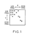
- the coefficients are mainly concentrated on a low frequency zone along the horizontal and vertical directions while they are seldom on a high frequency zone along the horizontal and vertical directions. This means that electric power of low frequen cy components of the coefficients is greater than electric power of high frequency components of the coefficients.
- the high frequency components of the significant coefficients are apt to be isolated from the other significant coefficients, as depicted at A and B.
- the illustrated high frequency components A and B be called first and second high frequency components, respectively, and are assumed to have high and low levels of electric power. Therefore, neglection of the first frequency component A gives rise to serious degradation of a picture quality while neglection of the second frequency component B hardly degrades the picture quality.
- a threshold level TH is selected, for example, between the first and the second quantization levels QL1 and QL2, as shown at a broken line in Fig. 2, and is used to determine a significant area which is defined in each block in a manner to be described.
- the second frequency component B is judged to be outside of the significant area and neglected because the second frequency component B is lower than the threshold level TH as illustrated in Fig. 2.
- the second frequency component B is placed inside of a nonsignificant area and judged to be invalid while the third frequency component C in the significant area is judged to be valid.
- Such judgement is possible by monitoring the order of scanning the coefficients in addition to the signal levels of the coefficients.
- quantization is carried out only about the significant coefficients placed within the significant area.
- encoding must be carried out within a first range F1 from the d.c. component to the second frequency component B, although no encoding is carried out between the second frequency component B and the block end.
- encoding may be carried out in a second range F2 between the d.c. component and the first frequency component A.
- the comparison result signals CR are delivered to a classifying circuit, depicted at a broken line block 20, together with the coefficient signal sequence CO.
- the classifying circuit 20 comprises an area decision circuit 21 operable in response to the comparison result signal CR to decide a significant area which includes significant ones of the coefficients.
- the area decision circuit 21 may carry out a preselected operation selected from the zone detection, the zigzag scanning, and, the adaptive scanning in a known manner.
- the comparison result signals CR are subjected to such a preselected operation in the respective blocks.
- the comparison result signals CR are collected and memorized in a memory (not shown) to be collated with each of the candidate areas, as shown in Fig. 7. More specifically, significant ones of the comparison result signals are distributed in the memory to show a distribution specified by an area outline or configuration similar to either one of the candidate areas. Each of the candidate areas is successively compared with the area configuration to select a minimum one of the candidate areas that includes all of the significant comparison result signals. A result of selection is produced from the area decision circuit 21 as a significant area signal AS (Fig. 6) to specify which one of the candidate areas is selected.
- the zigzag scanning is assumed to be used in the area decision circuit 21 so as to decide the significant area.
- the comparison result signals are scanned at every block on the memory of the area decision circuit 21 in the manner illustrated in Figs. 5(A) and 5(B).
- the significant comparison result signals CR (Fig. 6) are depicted at crisscrosses and scanned in a zigzag manner as shown by a solid line. Such zigzag scanning is progressive from the low frequency component towards the high frequency components.
- a final one of the significant comparison result signals is scanned in the above-mentioned manner, zero or nonsignificant ones of the comparison result signals follows the final significant comparison result signal until a block end, as shown by a broken line in Fig. 8.
- the nonsignificant comparison result signals need not always be encoded. In other words, the zigzag scanning may be stopped at the final significant comparison result signal.
- the EOB (end of block) code is substituted for the nonsignificant comparison result signals.
- the zigzag scanning becomes effective as the nonsignificant comparison result signals becomes long.
- the adaptive scanning may be used to decide the significant area in the area decision circuit 21 illustrated in Fig. 6.
- optimum scanning is selected from the vertical scanning, the horizontal scanning, and the zigzag scanning by monitoring a length of nonsignificant comparison result signals following a final one of significant comparison result signals. Specifically, each length of the nonsignificant comparison result signals is calculated on carrying out the vertical scanning, the horizontal scanning, and the zigzag scanning.
- the optimum scanning decided is either one of the vertical scanning, the horizontal scanning, and the zigzag scanning that provides a maximum length of the nonsignificant comparison result signals.
- Let the significant comparison result signals have distributions illustrated at CD1, CD2, and CD3 in Fig. 7.
- a selected one of the vertical scanning, the horizontal scanning, and the zigzag scanning is decided as the optimum scanning in connection with the distributions CD1, CD2, and CD3, as readily seen from Fig. 7.
- the scannings are switched from one to another in the adaptive scanning.
- the coefficient signal sequence CO is supplied direct to a judging circuit 25 through no intervention between the linear transform circuit 12 and the judging circuit 25.
- the judging circuit 25 is put into an active state during reception of the significant area signal AS produced in the above-mentioned manner. As a result, the judging circuit 25 judges the coefficients to be valid during presence of the significant area signal AS. Otherwise, the coefficients are judged to be invalid.
- the judging circuit 25 serves to judge whether or not the coefficients of each block are present inside of the significant area and to successively classify each of first and second species coefficients which are valid and invalid in each block in consideration of the significant area signal AS.
- the coefficient signal sequence CO is preliminarily processed prior to quantization into the significant signal sequence SC by a combination of the threshold circuit 16, the comparator 17, the area decision circuit 21, the judging circuit 25, and the rearranging circuit 28.
- the significant signal sequence SC and the significant area signal AC may be collectively referred to as a sequence of preliminary processed signals.
- the area decision circuit 21, the judging circuit 25, and the rearranging circuit 28 are operable to classify the coefficients into the first and the second species coefficients, as described before, and thereafter serve as the classifying circuit 20.
- the illustrated controller 31 also supplies the threshold circuit 16 with a quantization control signal C2 which is indicative of the threshold level TH.
- the threshold level TH may be either invariable within each block or variable at every one of the coefficients placed within each block.
- both the quantization characteristic and the threshold level TH may be varied so as to effectively control an amount of information to be encoded.
- the significant area signal AS and the quantized signal sequence QS are supplied to an encoder circuit 33 to be subjected to posterior processing which may be variable length encoding.
- the encoder circuit 33 is also supplied with the quantization control signal C1 to specify the selected quantization characteristic.
- the significant area signal AS carries information indicative of a selected one of the candidate areas or zones, such as CD1 and CD2 (Fig. 7), when the area or zone detection is used in the area decision circuit 21.
- the significant area signal AS On the zigzag scanning, the significant area signal AS carries the EOB code after the significant comparison result signals.
- the significant area signal AS carries, in addition to the EOB code, information indicative of the optimum scanning.
- an encoding system comprise similar parts designated by like reference numerals and symbols.
- the classifying circuit 20 comprises a first area decision circuit 21 ⁇ without a rearrangement circuit, such as 28 in Fig. 6.
- the first area decision circuit 21 ⁇ decodes a significant quantization area in response to the comparison result signal sequence CR by carrying out either the zone detection or the zigzag scanning. This means that the adaptive scanning is not used in the illustrated classifying circuit 20. In this connection, no rearrangement circuit is necessary in the illustrated classifying circuit 20.
- the second species coefficients are sent to the quantizer 25 together with the first species coefficients.
- the quantizer 25 quantizes not only the first species coefficients but also the second species coefficients into a sequence of quantized signals QS′.
- the illustrated quantized signal sequence QS ⁇ is delivered to a rearrangement circuit 28 ⁇ and a second area decision circuit 35.
- the rearrangement circuit 28′ may be similar in structure and operation to that illustrated in Fig. 6.
- the second area decision circuit 35 carries out the adaptive scanning in the manner mentioned in Fig. 6 to determine optimum scanning of the vertical scanning, the horizontal scanning, and the zigzag scanning and to produce an optimum scanning signal OP representative of the optimum scanning.
- the rearrangement circuit 28 ⁇ rearranges the quantized signal sequence QS ⁇ into a sequence of rearranged signals RA ⁇ in accordance with the optimum scanning signal OP.
- the rearranged signal sequence RA ⁇ therefore conveys the coefficients quantized by the quantizer 25.
- a combination of the second area decision circuit 35, the rearrangement circuit 28 ⁇ , and the encoder circuit 33 is located after the quantizer to process the quantized signal sequence QS ⁇ and may be referred to as a posterior processing circuit for carrying out posterior processing.
- the illustrated quantized signal sequence QS ⁇ suppresses isolated high frequency components, such as B in Fig. 2, having a level lower than the threshold level TH, because the significant area is decided by the first area decision circuit 21 ⁇ .
- the rearrangement circuit 28 ⁇ may comprise a memory (not shown) for successively storing the quantized signal sequence SC and an address control circuit (not shown also) for scanning memory addresses in the order determined for the optimum scanning.
- Such a rearrangement circuit 28 ⁇ is known in the art and will not be described any longer.
- the rearranged signal sequence RA ⁇ , the optimum scanning signal OP, and the quantization control signal C1 are encoded by the encoder circuit 33 into a sequence of encoded signals EC.
- the second area decision circuit 35 serves to determine the encoded signals EC sent to a transmission line and may be called a transmission area or zone decision circuit.
- an encoding system is for carrying out posterior processing after quantization.
- variable length encoding is carried out as the posterior processing.
- a quantizer 15 is also illustrated along with a posterior processing circuit for the posterior processing.
- the illustrated quantizer 15 comprises a quantization circuit 41 which may be supplied either with the significant coefficient signal sequence (Fig. 6) or with a combination of the first and the second species signals (Fig. 9).
- any other coefficient signal sequence may be given to the illustrated quantizer 15, if it is divided into a sequence of blocks. Taking this into consideration, the coefficient signal sequence is depicted at CF and is quantized in accordance with a quantization characteristic by the quantization circuit 41.
- Fig. 11 it is also assumed that the sampled signals or the picture elements of sixty-four are already stored in a manner similar to the sequential scanning. More particularly, first through eighth ones of the sampled signals are memorized in an uppermost or first row of Fig. 11 along a horizontal direction while ninth through sixteenth picture elements are memorized in a second row of Fig. 11 in the horizontal direction. Likewise, the remaining sampled signals are assigned to each row.
- zigzag scanning is progressive from the low frequency components of the coefficients towards the high frequency components, as described before.
- the quantized signals for the low frequency components have a distribution which is different from the quantized signals for the high frequency components.
- the distribution of the quantized signals for the low frequency components becomes dense in comparison with the distribution of the quantized signals for the high frequency components.
- the code set number signal NM is sent to a switching circuit 55 to successively select either one of the first through fifth code sets 46 to 50.
- a selected one of the first through fifth code sets 46 to 50 is connected in a time division fashion to a variable length encoder 56 supplied with the quantized signals QS.
- the variable length encoder 56 carries out the variable length encoding within each block in accordance with the first through fifth code set switched from one to another in the time division fashion and produces a sequence of encoded signals EC.
Abstract
Description
- This invention relates to an encoding system for use in carrying out encoding of a sequence of digital signals into a sequence of encoded signals with a high efficiency. It is to be noted here that the digital signal sequence may convey an audio signal, although description will be made about an image signal, and that such encoding will be called efficient coding in the instant specification.
- In order to carry out efficient coding of the type described, a sequence of digital signals is subdivided in each frame into a plurality of blocks and is subjected to a predetermined linear transform in the respective blocks. Such a linear transform may be, for example, Hadamard transform, Haar transform, Karhunen-Loéve transform, Discrete Cosine transform, or the like, and may collectively be called an orthogonal transform. At any rate, the digital signals of each block are converted into transform coefficients which have a statistic distribution in a frequency region between a d.c. component zone and a high frequency zone and which have variable levels of electric power.
- It is known in the art that electric power of the transform coefficients is locally distributed or concentrated on a local frequency zone which includes the d.c. component and a low frequency near the d.c. component. This shows that non-zero or significant ones of the transform coefficients mainly appear in the low frequency zone and scarcely appear in the high frequency zone while zero or nonsignificant ones of the transform coefficients mainly appear in the high frequency zone. Such nonsignificant coefficients need not always be transmitted through a transmission line.
- Under the circumstances, the transform coefficients are preliminarily processed prior to quantization of the transform coefficients, which will be called anterior processing. A conventional encoding system monitors as the anterior processing a distribution of the significant coefficients in each of the blocks to determine a minimum zone which covers all of the significant coefficients and to transmit only the coefficients of the minimum zone, together with a code assigned to the minimum zone in question. This encoding system may be called a zone detection system. With this zone detection system, transmission is not carried out as regards nonsignificant coefficients which are outside of the minimum zone.
- Alternatively, another conventional encoding system detects a final significant coefficient in each block and produces an End Of Block (EOB) code which is representative of continuation of nonsignificant coefficients after the EOB code. Such detection and production of the EOB code are carried out as the anterior processing. In order to effectively detect the EOB code, zigzag scanning is carried out in each block. The encoding system may be referred to as an EOB code system and is effective to reduce redundancy of the coefficients.
- Furthermore, still another conventional encoding system carries out the anterior processing by adaptively scanning the transform coefficients of each block in various manners to decide an optimum one of scanning operations that gives a maximum length of continuation of nonsignificant coefficients after a final significant transform coefficient. This system may be called a scanning encoder system and is helpful to reduce an amount of information to be transmitted.
- Herein, it is to be noted here that significant transform coefficients have a tendency to be isolated from the other significant transform coefficients in the high frequency zone, although such isolated significant transform coefficients seldom appear in the high frequency zone, as mentioned before.
- Accord ing to the inventors' experimental studies, it has been found out that removal or neglection of the isolated significant transform coefficients enables a considerable reduction of an amount of information but brings about a reduction of a picture quality from time to time. Accordingly, the experimental studies say that complete neglection of the isolated significant coefficients in the high frequency zone is not favorable in the light of a reduction of the picture quality.
- At any rate, the transform coefficients are quantized by a quantizer into a sequence of quantized signals after the above-mentioned anterior processing and are thereafter usually subjected by an encoding unit to variable length encoding which may be called posterior processing. Such posterior processing is carried out by the use of a single conversion table between the quantized signals and variable length codes. This means that the transform coefficients are encoded by the same conversion table, irrespective of the fact that they are present in the low and the high frequency zones. However, it has been also confirmed that the use of the same conversion table is not favorable in view of accomplishing a high efficiency because of the local concentration of the transform coefficients as mentioned before.
- It is an object of this invention to provide an encoding system which is capable of considerably reducing an amount of information to be transmitted, without any degradation of quality of a picture reproduced.
- It is another object of this invention to provide an encoding system of the type described, which can effectively process, prior to quantization, significant transform coefficients isolated in a high frequency zone from the other transform coefficients.
- It is a further object of this invention to provide an encoding system which can establish a high efficiency of encoding after quantization of a transform coefficient sequence.
- It is still another object of this invention to provide an encoding system of the type described, which is useful for carrying out variable length encoding of a sequence of quantized signals.
- It is yet another object of this invention to provide an encoding system of the type described, which can avoid that degradation of an effect of information compression which results from misadjustment between a distribution of transform coefficients and variable length encoding characteristics.
- An encoding system to which this invention is applicable is for use in encoding a sequence of digital signals into a sequence of encoded signals. The digital signal sequence is subjected to a predetermined linear transform into a sequence of coefficients which is divided into a sequence of blocks and which is produced as a sequence of coefficient signals. The encoding system comprises anterior processing means responsive to the coefficient signal sequence for processing the coefficients in the respective blocks into a sequence of preliminary processed signals, quantizing means coupled to the anterior processing means for quantizing the preliminary processed signals into a sequence of quantized signals, and posterior processing means for processing the quantized signal sequence into the encoded signal sequence. According to an aspect of this invention, the anterior processing means comprises threshold means for producing a threshold signal representative of a threshold level defined for the coefficients, comparing means responsive to the threshold signal and the coefficient signal sequence for successively comparing the coefficients with the threshold level in the respective blocks to produce a sequence of comparison result signals representative of results of comparison in the respective blocks, classifying means responsive to the comparison result signal sequence and the coefficient signal sequence for classifying the coefficients of each block with reference to the res ults of comparison into first and second species coefficients which are valid and invalid, respectively, to produce the first species coefficients as a sequence of significant coefficient signals, and supply means for supplying the significant coefficient signal sequence to the quantizing means as the preliminary processed signal.
- According to another aspect of this invention, the posterior processing means carries out variable length coding of the quantized signal sequence to produce variable length codes as the encoded signals and comprises memory means for memorizing a plurality of code sets which are different from one another and which define mutual relationships between the quantized signals and the variable length codes, switching means for switching the code sets from one to another within each of the blocks to select either one of the code sets as a selected code set, and variable length encoding means coupled to the switching means and responsive to the quantized signal sequence for encoding the quantized signal sequence in accordance with the selected code set into the variable length codes.
-
- Fig. 1 is a view for use in describing coefficients distributed on a block;
- Fig. 2 is a graphical representation for use in describing signal levels of the coefficients which appear on sequentially scanning the coefficients illustrated in Fig. 1;
- Fig. 3 is a graphical representation for use in describing anterior processing of the coefficients shown in Fig. 2;
- Figs. 4(A) and (B) are views for describing zone or area detection which can be used in this invention;
- Figs. 5(A) and (B) are views for describing zigzag scanning which can be used in this invention;
- Fig. 6 is a block diagram of an encoding system according to a first embodiment of this invention;
- Fig. 7 is a view for use in describing operation of a part of the encoding system illustrated in Fig. 6;
- Fig. 8 is a view for use in describing another operation of the part of the encoding system illustrated in Fig. 6;
- Fig. 9 is a block diagram of an encoding system according to a second embodiment of this invention;
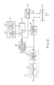
- Fig. 10 is a block diagram of an encoding system according to a third embodiment of this invention;
- Fig. 11 is a view for use in describing a portion of the encoding system illustrated in Fig. 10;
- Fig. 12 is a view for use in describing another portion of the encoding system illustrated in Fig. 10; and
- Fig. 13 is a block diagram of an encoding system according to a fourth embodiment of this invention.
- Referring to Figs. 1 and 2, description will be made as regards principles of this invention for a better understanding of this invention. In Fig. 1, an illustration is made about a sequence of significant coefficients (depicted at crisscrosses) which result from an orthogonal transform, such as Hadamard or Discrete Cosine transform, of a sequence of image signals and which are arranged in a single one of blocks shown by a rectangle. As regards a horizontal direction H of Fig. 1, the coefficients are arranged from a lefthand side towards a righthand side as the coefficients become high in frequency. As regards a vertical direction V, the coefficients are arranged downwards as the coefficients become high in frequency. In this connection, a d.c. component of the coefficient is placed at an uppermost and leftmost position of Fig. 1.
- As understood from Fig. 1, the coefficients are mainly concentrated on a low frequency zone along the horizontal and vertical directions while they are seldom on a high frequency zone along the horizontal and vertical directions. This means that electric power of low frequen cy components of the coefficients is greater than electric power of high frequency components of the coefficients.
- It is to be noted here that the high frequency components of the significant coefficients are apt to be isolated from the other significant coefficients, as depicted at A and B. The illustrated high frequency components A and B be called first and second high frequency components, respectively, and are assumed to have high and low levels of electric power. Therefore, neglection of the first frequency component A gives rise to serious degradation of a picture quality while neglection of the second frequency component B hardly degrades the picture quality.
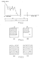
- Temporarily referring to Fig. 2, let the coefficients illustrated in Fig. 1 be sequentially scanned from the d.c. component along the horizontal direction and thereafter vertically scanned in a visual manner. Such scanning will be referred to as sequential scanning and brings about a signal variation as exemplified in Fig. 2. For convenience of description, a two-dimensional arrangement of the significant coefficients is rearranged in a one-dimensional arrangement in the order of scanning in Fig. 2. In this connection, the significant coefficients are arranged from low frequency components to high frequency ones in a direction from the lefthand side of an abscissa towards the righthand side. Each component of the significant coefficients has a signal level of electric power, as shown along an ordinate of Fig. 2.
- As illustrated in Fig. 2, the second frequency component B is higher in frequency than the first frequency component A and is lower in electric power than the latter. In Fig. 2, a nonsignificant coefficient C is present as a third frequency component in the lower frequency zone.
- In usual quantization, the coefficients are assumed to be quantized into a sequence of quantized signals by the use of first, second, third, and fourth quantization levels QL1, QL2, QL3, and QL4, respectively. In this event, quantization is carried out not only about the first frequency component A but also the second frequency component B because the first and the second frequency components A and B exceed the first quantization level QL1.
- According to this invention, a threshold level TH is selected, for example, between the first and the second quantization levels QL1 and QL2, as shown at a broken line in Fig. 2, and is used to determine a significant area which is defined in each block in a manner to be described. In this event, the second frequency component B is judged to be outside of the significant area and neglected because the second frequency component B is lower than the threshold level TH as illustrated in Fig. 2. In other words, the second frequency component B is placed inside of a nonsignificant area and judged to be invalid while the third frequency component C in the significant area is judged to be valid. Such judgement is possible by monitoring the order of scanning the coefficients in addition to the signal levels of the coefficients.
- After the significant area is determined by the use of the threshold level TH, quantization is carried out only about the significant coefficients placed within the significant area. By determining the significant area in each block, it is possible to considerably reduce an amount of information, as will become clear later.
- Referring to Fig. 3, let the coefficients illustrated in Fig. 2 be processed or encoded with reference to the first through fourth quantization levels QL1 to QL4 in a digital manner into a digital signal shown in Fig. 3. When the second frequency component B is encoded with the threshold level TH (Fig. 2) left out of consideration, encoding must be carried out within a first range F1 from the d.c. component to the second frequency component B, although no encoding is carried out between the second frequency component B and the block end. On the other hand, when the s ignificant area is defined with reference to the threshold level TH, encoding may be carried out in a second range F2 between the d.c. component and the first frequency component A. Accordingly, no encoding may be carried out in a third range F3 between the first and the second frequency components A and B. In this event, the third frequency component C (Fig. 2) is processed as a valid component because it is present in the significant area defined by the threshold level TH.
- Referring to Figs. 4(A) and 4(B), it is assumed that zone detection as mentioned in the preamble of the instant specification is used to detect a significant area of the significant coefficients distributed in the manner illustrated in Fig. 1. As shown in Fig. 4(A), no consideration of the threshold level TH (Fig. 2) provides a first minimum zone Z1 including the first and the second frequency components A and B. On the other hand, consideration of the threshold level TH results in a reduction of the first minimum zone Z1 to a second minimum zone Z2 excluding the second frequency component B. Thus, the zone detection is effective to determine the significant area with reference to the threshold level TH.
- Referring to Figs. 5(A) and 5(B), zigzag scanning may be used to define the significant area in connection with the arrangement of the significant coefficients illustrated in Fig. 1. When the second frequency coefficient B is judged to be significant or valid, the zigzag scanning must be continued until the second frequency component B. However, the zigzag scanning can be stopped at the first frequency component A when the second frequency component B is neglected with reference to the threshold level B.
- As readily understood from Fig. 5(B), it is possible to considerably reduce a scanning area by neglecting the second frequency component B in relation to the threshold level TH. Thus, the zigzag scanning can be also used to determine the significant area.
- An EOB code may be produced to specify a final one of the coefficients in each block when the zigzag scanning is carried out.
- In addition, the significant area can be determined by the use of an adaptive scanning technique wherein optimum scanning is selected from horizontal scanning, vertical scanning, and zigzag scanning.
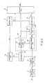
- Referring to Fig. 6, an encoding system according to a first embodiment of this invention is supplied with a sequence of input signals IN which may be given a digital form. The input signals IN may be a predictive error signal derived from an image signal in a manner described, for example, in United States Patent Application Serial No. 29,565 filed March 24, 1987, by M. Kaneko et al. The input signal sequence therefore carries a succession of picture elements. The input signal sequence IN is divided into a succession of frames and given to a
block division circuit 11 to be subdivided into a sequence of blocks in the respective frames. Such ablock division circuit 11 is known in the art and will not be described any longer. Theblock division circuit 11 produces a sequence of subdivided input signals as a sequence of digital signals DG and supplies the digital signal sequence DG to alinear transform circuit 12 for carrying out a predetermined linear transform, such as discrete cosine transform or the like. - In the
linear transform circuit 12, the digital signal sequence DG is subjected in a known manner to the predetermined linear transform into a sequence of coefficients. As known in the art, the picture elements of a preselected number N1 × N2 are transformed into the coefficients of the same number. Let the coefficient sequence be divided into a sequence of coefficient blocks each of which includes the coefficients equal in number to the picture elements included in each block. - In Fig. 6, the coefficient sequence is produced as a sequence of coefficient signals CO and subjected to anterior or preliminary processing prior to quantization which is carried out in a
quantizer 15. In order to carry out the anterior processing, the illustrated encoding system comprises athreshold circuit 16 for producing a threshold signal th which is representative of a threshold level TH exemplified in Fig. 2. Acomparator 17 is supplied with the coefficient signal sequence CO and the threshold signal th. Thecomparator 17 successively compares each of the coefficients with the threshold level in the respective blocks to produce a comparison result signal CR representative of results of comparison in the respective blocks. In other words, the comparison result signals CR represent whether the coefficients are greater or not greater than the threshold level TH. - The comparison result signals CR are delivered to a classifying circuit, depicted at a
broken line block 20, together with the coefficient signal sequence CO. The classifyingcircuit 20 comprises anarea decision circuit 21 operable in response to the comparison result signal CR to decide a significant area which includes significant ones of the coefficients. To this end, thearea decision circuit 21 may carry out a preselected operation selected from the zone detection, the zigzag scanning, and, the adaptive scanning in a known manner. However, it should be noted that the comparison result signals CR are subjected to such a preselected operation in the respective blocks. - Let the zone detection be carried out in the
area decision circuit 21 so as to determine the significant area for the comparison result signals CR. In this event, an optimum area is selected as the significant area from a plurality of candidate areas in thearea decision circuit 21. - Temporarily referring to Fig. 7, first through third ones CD1 to CD3 of the candidate areas are exemplified which are prepared in the
area decision circuit 21. The first candidate area CD1 is elongated in a vertical direction while the second candidate area CD2 is extended along a horizontal direction. In addition, the third candidate area CD3 is of a sector shape. - In the
area decision circuit 21, the comparison result signals CR are collected and memorized in a memory (not shown) to be collated with each of the candidate areas, as shown in Fig. 7. More specifically, significant ones of the comparison result signals are distributed in the memory to show a distribution specified by an area outline or configuration similar to either one of the candidate areas. Each of the candidate areas is successively compared with the area configuration to select a minimum one of the candidate areas that includes all of the significant comparison result signals. A result of selection is produced from thearea decision circuit 21 as a significant area signal AS (Fig. 6) to specify which one of the candidate areas is selected. - Alternatively, the zigzag scanning is assumed to be used in the
area decision circuit 21 so as to decide the significant area. In this case, the comparison result signals are scanned at every block on the memory of thearea decision circuit 21 in the manner illustrated in Figs. 5(A) and 5(B). - Referring to Fig. 8, the significant comparison result signals CR (Fig. 6) are depicted at crisscrosses and scanned in a zigzag manner as shown by a solid line. Such zigzag scanning is progressive from the low frequency component towards the high frequency components. When a final one of the significant comparison result signals is scanned in the above-mentioned manner, zero or nonsignificant ones of the comparison result signals follows the final significant comparison result signal until a block end, as shown by a broken line in Fig. 8. The nonsignificant comparison result signals need not always be encoded. In other words, the zigzag scanning may be stopped at the final significant comparison result signal. When no zigzag scanning is carried out as regards the nonsignificant comparison result s ignals following the final significant comparison result signal, the EOB (end of block) code is substituted for the nonsignificant comparison result signals. The zigzag scanning becomes effective as the nonsignificant comparison result signals becomes long.
- It is also possible to produce the number of the significant comparison result signals instead of the EOB code. At any rate, the significant area signal AS is produced from the
area decision circuit 21 until production of the EOB code or detection of the final significant comparison result signal. - Furthermore, the adaptive scanning may be used to decide the significant area in the
area decision circuit 21 illustrated in Fig. 6. In the adaptive scanning, optimum scanning is selected from the vertical scanning, the horizontal scanning, and the zigzag scanning by monitoring a length of nonsignificant comparison result signals following a final one of significant comparison result signals. Specifically, each length of the nonsignificant comparison result signals is calculated on carrying out the vertical scanning, the horizontal scanning, and the zigzag scanning. As the optimum scanning, decided is either one of the vertical scanning, the horizontal scanning, and the zigzag scanning that provides a maximum length of the nonsignificant comparison result signals. Let the significant comparison result signals have distributions illustrated at CD1, CD2, and CD3 in Fig. 7. A selected one of the vertical scanning, the horizontal scanning, and the zigzag scanning is decided as the optimum scanning in connection with the distributions CD1, CD2, and CD3, as readily seen from Fig. 7. - Thus, the scannings are switched from one to another in the adaptive scanning. This shows that the optimum scanning may be different from scanning carried out as regards the coefficients in the
block division circuit 11 and that the coefficients must be rearranged in dependency upon the optimum scanning when the adaptive scanning is carried out in thearea decision circuit 21. - In this event, the significant area signal AS is produced from the
area decision circuit 21 until the final significant comparison result signal, together with an optimum scanning signal OP (Fig. 6) representative of the optimum scanning. - Referring back to Fig. 6, either one of the area detection and the zigzag scanning is assumed to be used in the
area decision circuit 21. Under the circumstances, the coefficient signal sequence CO is supplied direct to a judgingcircuit 25 through no intervention between thelinear transform circuit 12 and the judgingcircuit 25. The judgingcircuit 25 is put into an active state during reception of the significant area signal AS produced in the above-mentioned manner. As a result, the judgingcircuit 25 judges the coefficients to be valid during presence of the significant area signal AS. Otherwise, the coefficients are judged to be invalid. From this fact, it is readily understood that the judgingcircuit 25 serves to judge whether or not the coefficients of each block are present inside of the significant area and to successively classify each of first and second species coefficients which are valid and invalid in each block in consideration of the significant area signal AS. - As a result, only the first species coefficients are produced as a sequence of significant coefficient signals SC. Thus, the significant coefficient signal sequence SC appears when the coefficients are present inside of the significant area.
- On the other hand, when the coefficients are judged to be the second species coefficients due to the fact that the coefficients are not present in the significant area, none of the significant coefficient signals are produced by the judging
circuit 25 with the coefficients in question suppressed. - In Fig. 6, let the
area decision circuit 21 carry out the adaptive scanning in the above-mentioned manner to produce the significant area signal AS together with the optimum scanning signal OP. As mentioned before, the coefficient signals CO must be rearranged in accordance with the optimum scanning signal OP. To this end, the coefficient signal sequence CO is sent torearrangement circuit 28 which is known in the art. Supplied with the optimum scanning signal OP, therearrangement circuit 28 rearranges the coefficient signal sequence CO into a sequence of rearranged coefficient signals RA by scanning the coefficient signals again in accordance with the optimum scanning determined by thearea decision circuit 21. The rearranged coefficient signal sequence RA conveys the coefficients which are not subjected to quantization and is sent to the judgingcircuit 25 to be processed in the above-mentioned manner into the significant signal sequence SC. - Thus, the coefficient signal sequence CO is preliminarily processed prior to quantization into the significant signal sequence SC by a combination of the
threshold circuit 16, thecomparator 17, thearea decision circuit 21, the judgingcircuit 25, and the rearrangingcircuit 28. In this connection, the significant signal sequence SC and the significant area signal AC may be collectively referred to as a sequence of preliminary processed signals. Moreover, thearea decision circuit 21, the judgingcircuit 25, and the rearrangingcircuit 28 are operable to classify the coefficients into the first and the second species coefficients, as described before, and thereafter serve as the classifyingcircuit 20. - In Fig. 6, the
quantizer 15 may comprise a quantization circuit and a sample memory, as will later be described, and quantizes the significant coefficient signal sequence SC into a sequence of quantized signals QS in accordance with a quantization characteristic. The quantization characteristic may be selected from a plurality of quantization characteristics as a selected quantization characteristic in a known manner and switched to another quantization characteristic at every predetermined interval of time, for example, each frame. In order to control thequantizer 15, acontroller 31 produces a quantization control signal C1 indicative of the selected characteristic and supplies the quantization control signal C1 to thequantizer 15. - The illustrated
controller 31 also supplies thethreshold circuit 16 with a quantization control signal C2 which is indicative of the threshold level TH. The threshold level TH may be either invariable within each block or variable at every one of the coefficients placed within each block. In addition, both the quantization characteristic and the threshold level TH may be varied so as to effectively control an amount of information to be encoded. - The significant area signal AS and the quantized signal sequence QS are supplied to an
encoder circuit 33 to be subjected to posterior processing which may be variable length encoding. In the illustrated example, theencoder circuit 33 is also supplied with the quantization control signal C1 to specify the selected quantization characteristic. Herein, the significant area signal AS carries information indicative of a selected one of the candidate areas or zones, such as CD1 and CD2 (Fig. 7), when the area or zone detection is used in thearea decision circuit 21. On the zigzag scanning, the significant area signal AS carries the EOB code after the significant comparison result signals. On the adaptive scanning, the significant area signal AS carries, in addition to the EOB code, information indicative of the optimum scanning. - In any event, the
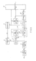
encoder circuit 33 encodes the significant area signal AS, the quantized signal sequence QS, and the quantization control signal C1 into a sequence of encoded signals EC which is sent through a transmission line or path to a decoding system (not shown). - Referring to Fig. 9, an encoding system according to a second embodiment of this invention comprise similar parts designated by like reference numerals and symbols. In Fig. 9, it is to be noted that the classifying
circuit 20 comprises a first area decision circuit 21ʹ without a rearrangement circuit, such as 28 in Fig. 6. The first area decision circuit 21ʹ decodes a significant quantization area in response to the comparison result signal sequence CR by carrying out either the zone detection or the zigzag scanning. This means that the adaptive scanning is not used in the illustrated classifyingcircuit 20. In this connection, no rearrangement circuit is necessary in the illustrated classifyingcircuit 20. - The coefficient signal sequence CO is sequentially given to the judging
circuit 25 without changing the order of the coefficients while the significant area signal AS is given to the judgingcircuit 25 in the manner mentioned in conjunction with the zone detection and the zigzag scanning in Fig. 6. With this structure, the coefficients within the significant area are judged in the judgingcircuit 25 to be the first species coefficients and are produced as the significant coefficient signals SC. On the other hand, the coefficients outside of the significant area are forced to be zero or nonsignificant coefficients which may be called the second species coefficients. - In the example being illustrated, the second species coefficients are sent to the
quantizer 25 together with the first species coefficients. As a result, thequantizer 25 quantizes not only the first species coefficients but also the second species coefficients into a sequence of quantized signals QS′. - The illustrated quantized signal sequence QSʹ is delivered to a rearrangement circuit 28ʹ and a second
area decision circuit 35. Therearrangement circuit 28′ may be similar in structure and operation to that illustrated in Fig. 6. - The second
area decision circuit 35 carries out the adaptive scanning in the manner mentioned in Fig. 6 to determine optimum scanning of the vertical scanning, the horizontal scanning, and the zigzag scanning and to produce an optimum scanning signal OP representative of the optimum scanning. The rearrangement circuit 28ʹ rearranges the quantized signal sequence QSʹ into a sequence of rearranged signals RAʹ in accordance with the optimum scanning signal OP. The rearranged signal sequence RAʹ therefore conveys the coefficients quantized by thequantizer 25. Thus, a combination of the secondarea decision circuit 35, the rearrangement circuit 28ʹ, and theencoder circuit 33 is located after the quantizer to process the quantized signal sequence QSʹ and may be referred to as a posterior processing circuit for carrying out posterior processing. - The illustrated quantized signal sequence QSʹ suppresses isolated high frequency components, such as B in Fig. 2, having a level lower than the threshold level TH, because the significant area is decided by the first area decision circuit 21ʹ. Although such suppressed components are quantized by the
quantizer 25 and rearranged by the rearrangement circuit 28ʹ, they seldom appear in the rearranged signal sequence RAʹ by carrying out the optimum scanning in the rearrangement circuit 28ʹ. For this purpose, the rearrangement circuit 28ʹ may comprise a memory (not shown) for successively storing the quantized signal sequence SC and an address control circuit (not shown also) for scanning memory addresses in the order determined for the optimum scanning. Such a rearrangement circuit 28ʹ is known in the art and will not be described any longer. - The rearranged signal sequence RAʹ, the optimum scanning signal OP, and the quantization control signal C1 are encoded by the
encoder circuit 33 into a sequence of encoded signals EC. At any rate, the secondarea decision circuit 35 serves to determine the encoded signals EC sent to a transmission line and may be called a transmission area or zone decision circuit. - Referring to Fig. 10 , an encoding system according to a third embodiment of this invention is for carrying out posterior processing after quantization. In the example being illustrated, variable length encoding is carried out as the posterior processing. In Fig. 10, a
quantizer 15 is also illustrated along with a posterior processing circuit for the posterior processing. The illustratedquantizer 15 comprises aquantization circuit 41 which may be supplied either with the significant coefficient signal sequence (Fig. 6) or with a combination of the first and the second species signals (Fig. 9). In addition, any other coefficient signal sequence may be given to the illustratedquantizer 15, if it is divided into a sequence of blocks. Taking this into consideration, the coefficient signal sequence is depicted at CF and is quantized in accordance with a quantization characteristic by thequantization circuit 41. The quantization characteristic may be changed to another one under control of a controller, such as 31 in Figs. 6 and 9. As a result of quantization, a sequence of sampled signals is successively stored in asample readout circuit 42 which is operable as a part of thequantizer 15 and which may be a memory circuit. - Herein, it is assumed that each of the sample signals may be made to correspond to a picture element and that each block is composed of a predetermined number of the picture elements, such as 4 × 4, 8 × 8, 16 × 16, or the like. For brevity of description, let the predetermined number be equal to 8 × 8, namely, sixty-four.
- Referring to Fig. 11, it is also assumed that the sampled signals or the picture elements of sixty-four are already stored in a manner similar to the sequential scanning. More particularly, first through eighth ones of the sampled signals are memorized in an uppermost or first row of Fig. 11 along a horizontal direction while ninth through sixteenth picture elements are memorized in a second row of Fig. 11 in the horizontal direction. Likewise, the remaining sampled signals are assigned to each row.
- In Figs. 10 and 11, the sampled signals are successively read out of the
sample readout circuit 42 in numerical order from unity to sixty-four under control of areadout control circuit 43. To this end, thereadout control circuit 43 supplies thesample readout circuit 42 with an address indication signal ADD which specifies each address in the numerical order illustrated in Fig. 11 and which may be called a synchronizing signal. As a result, zigzag scanning is carried out on thesample readout circuit 42 to produce a sequence of quantized signals depicted at QS in Fig. 10. - In the meanwhile, zigzag scanning is progressive from the low frequency components of the coefficients towards the high frequency components, as described before. This is true of the sampled signals or quantized signals derived from the coefficients. From this fact, it is understood that the quantized signals for the low frequency components have a distribution which is different from the quantized signals for the high frequency components. In other words, the distribution of the quantized signals for the low frequency components becomes dense in comparison with the distribution of the quantized signals for the high frequency components.
- Under the circumstances, high efficiency of encoding or posterior processing can be accomplished, if both the quantized signals for the low and the high frequency components can be encoded into short length codes, respectively. This means that the quantized signals for the low and the high frequency components are preferably encoded in accordance with different code sets.
- Taking the above into consideration, a plurality of code sets are memorized in a variable
length code memory 45 to define different mutual relationships between each quantized signal QS and the corresponding variable length code. The illustratedvariable code memory 45 memorizes first through fifth on es of the code sets 46 to 50 which may be numbered from unity to five, respectively, and which are switched from one to another, as will become clear soon. - Referring to Fig. 12 in addition to Fig. 10, the address indication signal ADD for the zigzag scanning is also delivered to a code set
indication circuit 53 which memorizes a conversion table illustrated in Fig. 12. Supplied with the address indication signal ADD which specifies table addresses in the numerical order illustrated in Fig. 11, the code setindication circuit 53 produces a code set number signal NM which is assigned to the first through fifth code sets 46 to 50 and which is represented by 1 to 5 in Fig. 12. As illustrated in Fig. 12, the first and the second code sets 46 to 48 are selected for the low frequency components while the fourth and the fifth code sets 49 and 50 are selected for the high frequency components. - In Fig. 10, the code set number signal NM is sent to a
switching circuit 55 to successively select either one of the first through fifth code sets 46 to 50. As a result, a selected one of the first through fifth code sets 46 to 50 is connected in a time division fashion to avariable length encoder 56 supplied with the quantized signals QS. Thevariable length encoder 56 carries out the variable length encoding within each block in accordance with the first through fifth code set switched from one to another in the time division fashion and produces a sequence of encoded signals EC. - With this structure, it is possible to represent both the low and the high frequency components by short length codes, respectively, and to therefore accomplish high efficiency of the encoding. The variable length codes of each code set may have common code patterns in each of the remaining code sets and may be equal in number to those of the remaining code sets. However, relationships between the quantized signals and the code patterns must be different from one another in the first through fifth code sets.
- Referring to Fig. 13, an encoding system according to a fourth embodiment of this invention is for carrying out variable length encoding as posterior processing by detecting a final one of significant coefficients which are produced in the form of quantized signals QC. More particularly, the coefficient signal sequence CF is quantized by the
quantization circuit 41 into a sequence of sampled signals which is stored in a sample readout circuit 42ʹ. The sampled signal sequence is read out of the sample readout circuit 52ʹ as the quantized signal sequence QC. Either one of the sequential scanning or the zigzag scanning may be carried out so as to read the sampled signal sequence QC out of the sample readout circuit 42ʹ. - The quantized signal sequence QC is delivered to a
variable length encoder 56 similar to that illustrated in Fig. 10 on one hand and to a finalsignificant coefficient detector 60 on the other hand. - The final
significant coefficient detector 60 monitors the quantized signal sequence QC to detect the final significant coefficient which is followed in each block by continuation of the nonsignificant coefficients. In other words, detection is made in the finalsignificant coefficient detector 60 about a leading one of the nonsignificant coefficients that next follows the final significant coefficient. Thedetector 60 further detects a nonsignificant position of the leading nonsignificant coefficient to find another position preceding the nonsignificant position and recognizes the preceding position as a position for the final significant coefficient. - The illustrated encoding system comprises a variable
length code memory 45 which memorizes first and second code tables 61 and 62 for defining different mutual relationships between each of the quantized signals QC and the corresponding variable length code. It is to be noted that the second code table 62 is used only when the final significant coeffici ent is detected by the finalsignificant coefficient detector 60. This means that variable length coding is usually carried out by the use of the first code table 61 except for the final significant coefficient. The code patterns of the variable length codes in the first code table 61 may be equal in number to the code patterns of the variable length codes in the second code table 62. However, a relationship between each code pattern of the first code table 61 and the corresponding quantized signal is different from a similar relationship of the second code table 62. - In Fig. 13, the first code table 61 is connected to a
variable length encoder 56 through a switchingcircuit 55 insofar as the final significant coefficient is not detected in each block by the finalsignificant coefficient detector 60. As a result, the quantized signals QC are quantized in accordance with the first code table 61. - On the other hand, the final
significant coefficient detector 60 sends a switching signal SW to the switchingcircuit 55 on detecting the final significant coefficient in the above-mentioned manner. In this case, thevariable length encoder 56 is connected through the switchingcircuit 55 to the second code table 62 and encodes the quantized signals QC into a sequence of encoded signals EC in accordance with the second code table 62. - In the example being illustrated, the switching signal SW is sent to a block
end code generator 64. The blockend code generator 64 produces the EOB code immediately after the final significant coefficient in response to the switching signal SW. The EOB code is representative of the fact that only the nonsignificant coefficients follow in the block in question. - The encoded signal sequence EC and the EOB code are multiplexed by a
multiplexer 66 into a sequence of transmission signals TR which is sent to a transmission line. - On decoding the transmission signal sequence TR in a decoder system (not shown), the variable length codes carried by the transmission signal sequence TR are decoded by the use of first and second decoding tables corresponding to the first and the second code tables 61 and 62, respectively. Specifically, usual decoding operation is carried out with reference to the first decoding table. The final significant coefficient is also once decoded by the use of the first significant coefficient. On decoding the final significant coefficient, the EOB code is also detected by the decoding system.
- In this situation, the decoding system cancels the decoded final significant coefficient and decodes the final significant coefficient again in accordance with the second decoding table.
- With this structure, the final significant coefficient alone is encoded by the use of the second code table 62 as described before, use of the first and the second code tables 61 and 62 enables high efficiency of encoding. This is because the final significant coefficient has a distribution which is quite different from the remaining significant coefficients and a reduction in efficiency of encoding is inevitable when such a final significant coefficient is encoded by the use of a common code table.
- While this invention has thus far been described in conjunction with several embodiments thereof, it will readily be possible for those skilled in the art to put this invention into practice in various other manners. For example, the digital signal sequence may be subjected to predictive encoding and may convey an audio signal instead of the image signal. Any other encoding may be substituted for the variable length encoding as the posterior processing.
Claims (10)
threshold means for producing a threshold signal representative of a threshold level defined for said coefficients;
comparing means responsive to said threshold signal and said coefficient signal sequence for successively comparing said coefficients with said threshold level in the respective blocks to produce a sequence of comparison result signals representative of results of comparison in the respective blocks;
classifying means responsive to said comparison result signal sequence and said coefficient signal sequence for classifying said coefficients of each block with reference to said results of comparison into first and second species coefficients which are valid and invalid, respectively, to produce a sequence of significant coefficient signals; and
supply means for supplying said significant coefficient signal sequence to said quantizing means as said preliminary processed signals.
determining means coupled to said comparing means for determining a significant area of said first species coefficients in every one of said blocks by collecting said comparison result signals in each of said blocks to produce a significant area signal representative of said significant area; and
judging means responsive to said significant area signal and said coefficient signal sequence for judging whether the coefficients of each block are present inside of said significant area to successively classify each of said coefficients into said first and said second species coefficients and to produce said significant coefficient signal sequence.
said quantized signal sequence carrying said first and said second species coefficients;
said posterior processing means comprising:
selecting means responsive to said quantized signal sequence for selecting an optimum scanning method from a plurality of different scanning methods to produce an optimum scanning signal representative of said optimum scanning method;
rearranging means responsive to said quantized signal sequence and said optimum scanning signal for rearranging said quantized signal sequence into a sequence of rearranged signals with reference to said optimum scanning signal; and
encoding means coupled to said rearranging means for encoding said rearranged signal sequence into said encoded signal sequence.
said judging means comprising:
rearranging means responsive to said optimum scanning signal for rearranging said coefficient signal sequence into a sequence of rearranged signals; and
detecting means responsive to said rearranged signal sequence and said significant area signal for detecting said first species coefficients from said rearranged signal sequence with reference to said significant area signal to produce said first species coefficients as said significant coefficient signal sequence.
memory means for memorizing a plurality of code sets which are different from one another and which define mutual relationships between said quantized signals and said variable length codes;
switching means for switching said code sets from one to another within each of said blocks to select either one of said code sets as a selected code set; and
variable length encoding means coupled to said switching means and responsive to said quantized signal sequence for encoding said quantized signal sequence in accordance with said selected code set into said variable length codes.
code set indicating means for successively indicating said code sets one at a time in each of said blocks to produce an indication signal representative of each of said code sets in synchronism with each of said quantized signals; and
switch means coupled to said code set indicating means, said memory means, and said variable length encoding means for switching said code sets from one to another in response to said indication signal to selectively connect said code sets to said variable length encoding means.
detecting means responsive to said quantized signals corresponding to the respective coefficients for detecting a final one of said significant coefficients in each of said blocks to produce a switch signal on detection of said final one of the significant coefficients; and
switch means coupled to said detecting means, said memory means, and said variable length encoding means for switching said code sets from one to another in response to said switch signal to selectively connect said code sets to said variable length encoding means.
memory means for memorizing a plurality of code sets which are different from one another and which define mutual relationships between said quantized signals and said variable length codes;
switching means for switching said code sets from one to another within each of said blocks to select either one of said code sets as a selected code set;
variable length encoding means coupled to said switching means and responsive to said quantized signal sequence for encoding said quantized signal sequence in accordance with said selected code set into said variable length codes.
Applications Claiming Priority (4)
| Application Number | Priority Date | Filing Date | Title |
|---|---|---|---|
| JP61267338A JPH0832036B2 (en) | 1986-11-10 | 1986-11-10 | Transform coefficient coding method |
| JP61267339A JPS63121321A (en) | 1986-11-10 | 1986-11-10 | High efficiency encoding system |
| JP267339/86 | 1986-11-10 | ||
| JP267338/86 | 1986-11-10 |
Publications (2)
| Publication Number | Publication Date |
|---|---|
| EP0267578A1 true EP0267578A1 (en) | 1988-05-18 |
| EP0267578B1 EP0267578B1 (en) | 1993-05-19 |
Family
ID=26547828
Family Applications (1)
| Application Number | Title | Priority Date | Filing Date |
|---|---|---|---|
| EP87116590A Expired - Lifetime EP0267578B1 (en) | 1986-11-10 | 1987-11-10 | Encoding system capable of accomplishing a high efficiency by anterior and/or posterior processing to quantization |
Country Status (4)
| Country | Link |
|---|---|
| US (1) | US4908862A (en) |
| EP (1) | EP0267578B1 (en) |
| CA (1) | CA1296430C (en) |
| DE (1) | DE3785911T2 (en) |
Cited By (26)
| Publication number | Priority date | Publication date | Assignee | Title |
|---|---|---|---|---|
| FR2636802A1 (en) * | 1988-09-19 | 1990-03-23 | France Etat | METHOD FOR QUANTIFYING A VARIABLE THRESHOLD IN TRANSFORMATION CODING FOR THE TRANSMISSION OF IMAGE SIGNALS |
| DE3940554A1 (en) * | 1988-12-10 | 1990-06-13 | Fuji Photo Film Co Ltd | COMPRESSION CODING DEVICE AND EXPANSION DECODING DEVICE FOR AN IMAGE SIGNAL |
| FR2640840A1 (en) * | 1988-12-16 | 1990-06-22 | Thomson Csf | Process for coding an image string, by a transformation and a plurality of variable-length codes, and devices for implementing this process |
| EP0401854A2 (en) * | 1989-06-09 | 1990-12-12 | Matsushita Electric Industrial Co., Ltd. | An apparatus for orthogonal transform coding |
| EP0406508A1 (en) * | 1989-07-04 | 1991-01-09 | Rai Radiotelevisione Italiana | Device for reducing the redundancy in blocks of digital video data in DCT encoding |
| EP0414074A2 (en) * | 1989-08-19 | 1991-02-27 | Mitsubishi Denki Kabushiki Kaisha | Transform coding apparatus |
| EP0426260A2 (en) * | 1989-11-03 | 1991-05-08 | Datacube Inc. | Adaptive zonal coder |
| EP0445727A2 (en) * | 1990-03-05 | 1991-09-11 | Mitsubishi Denki Kabushiki Kaisha | Variable length coding method |
| EP0470773A2 (en) * | 1990-08-06 | 1992-02-12 | Matsushita Electric Industrial Co., Ltd. | Orthogonal transform coding apparatus |
| EP0527011A2 (en) * | 1991-08-03 | 1993-02-10 | Sony Corporation | Variable length coding apparatus and method for motion vector |
| EP0597439A2 (en) * | 1992-11-09 | 1994-05-18 | Matsushita Electric Industrial Co., Ltd. | Variable-length data alignment apparatus for digital video data |
| US5371811A (en) * | 1987-07-09 | 1994-12-06 | British Telecommunications Public Limited Company | Data encoding |
| GB2279532A (en) * | 1993-06-21 | 1995-01-04 | Nec Corp | Compression/decompression of image data; sending control codes |
| EP0639032A2 (en) * | 1993-08-09 | 1995-02-15 | C-Cube Microsystems, Inc. | Structure and method for a multistandard video encoder/decoder |
| EP0732855A2 (en) * | 1995-03-15 | 1996-09-18 | Kabushiki Kaisha Toshiba | Moving picture coding and/or decoding system, and variable-length coding system |
| EP0800316A2 (en) * | 1989-10-14 | 1997-10-08 | Sony Corporation | Method of coding video signals and transmission system thereof |
| EP0827345A1 (en) * | 1995-03-17 | 1998-03-04 | Mitsubishi Denki Kabushiki Kaisha | Image encoding system |
| US5910909A (en) * | 1995-08-28 | 1999-06-08 | C-Cube Microsystems, Inc. | Non-linear digital filters for interlaced video signals and method thereof |
| US6104754A (en) * | 1995-03-15 | 2000-08-15 | Kabushiki Kaisha Toshiba | Moving picture coding and/or decoding systems, and variable-length coding and/or decoding system |
| EP1233375A2 (en) * | 2001-02-15 | 2002-08-21 | Sony Corporation | Image data encoding apparatus and method |
| AU2003235171B8 (en) * | 2002-04-19 | 2003-11-03 | Godo Kaisha Ip Bridge 1 | Variable Length Coding Method and Variable Length Decoding Method |
| US6704494B1 (en) | 1995-03-15 | 2004-03-09 | Kabushiki Kaisha Toshiba | Moving picture coding and/or decoding systems, and variable-length coding and/or decoding system |
| EP1445955A1 (en) * | 2001-11-16 | 2004-08-11 | NTT DoCoMo, Inc. | Image encoding method, image decoding method, image encoder, image decode, program, computer data signal, and image transmission system |
| US6911920B2 (en) | 2002-03-19 | 2005-06-28 | Fujitsu Limited | Hierarchical encoding and decoding devices |
| CN100542296C (en) * | 2002-04-19 | 2009-09-16 | 松下电器产业株式会社 | Variable length decoding method and device |
| AU2008201313B2 (en) * | 2002-04-19 | 2011-03-31 | Godo Kaisha Ip Bridge 1 | Variable length coding method and variable length decoding method |
Families Citing this family (15)
| Publication number | Priority date | Publication date | Assignee | Title |
|---|---|---|---|---|
| US5157743A (en) * | 1987-10-28 | 1992-10-20 | Canon Kabushiki Kaisha | Image information coding apparatus |
| JPH0379182A (en) * | 1989-08-23 | 1991-04-04 | Fujitsu Ltd | Image encoding control system |
| JP2883449B2 (en) * | 1990-12-27 | 1999-04-19 | 株式会社東芝 | Recording device |
| US5428693A (en) * | 1991-04-12 | 1995-06-27 | Mitsubishi Denki Kabushiki Kaisha | Motion compensation predicting coding method and apparatus |
| USRE37858E1 (en) | 1991-04-12 | 2002-09-24 | Mitsubishi Denki Kabushiki Kaisha | Motion compensation predicting encoding method and apparatus |
| JP2530090B2 (en) * | 1992-02-28 | 1996-09-04 | 三星電子株式会社 | Video signal encoder |
| JP2940304B2 (en) * | 1992-06-15 | 1999-08-25 | 松下電器産業株式会社 | High efficiency coding apparatus, high efficiency coding method, and decoding apparatus for high efficiency coding apparatus |
| US5226082A (en) * | 1992-07-02 | 1993-07-06 | At&T Bell Laboratories | Variable length decoder |
| KR950010913B1 (en) * | 1992-07-23 | 1995-09-25 | 삼성전자주식회사 | Vlc & vld system |
| US5510785A (en) * | 1993-03-19 | 1996-04-23 | Sony Corporation | Method of coding a digital signal, method of generating a coding table, coding apparatus and coding method |
| KR0155784B1 (en) | 1993-12-16 | 1998-12-15 | 김광호 | Adaptable variable coder/decoder method of image data |
| US5808683A (en) * | 1995-10-26 | 1998-09-15 | Sony Corporation | Subband image coding and decoding |
| JP3603000B2 (en) * | 2000-02-01 | 2004-12-15 | カネボウ株式会社 | Huffman encoding apparatus, Huffman encoding method, and recording medium recording Huffman encoding processing program |
| ITMI20011938A1 (en) * | 2001-09-17 | 2003-03-17 | Cit Alcatel | METHOD TO ENCRYPT A FLOW OF DATA |
| US7779558B2 (en) * | 2004-09-30 | 2010-08-24 | Asics Corporation | Shock absorbing device for shoe sole |
Citations (4)
| Publication number | Priority date | Publication date | Assignee | Title |
|---|---|---|---|---|
| US4189748A (en) * | 1977-08-23 | 1980-02-19 | Northrop Corporation | Video bandwidth reduction system using a two-dimensional transformation, and an adaptive filter with error correction |
| US4398217A (en) * | 1980-04-07 | 1983-08-09 | U.S. Philips Corporation | Method of and arrangement for digitizing a time-discrete video signal using a picture transform coding |
| US4504860A (en) * | 1981-07-22 | 1985-03-12 | British Telecommunications | Method and process for transmitting an image |
| EP0189703A1 (en) * | 1984-12-21 | 1986-08-06 | Thomson Grand Public | Method for the adaptive transform coding and decoding of a picture sequence, and device for carrying out such a method |
Family Cites Families (4)
| Publication number | Priority date | Publication date | Assignee | Title |
|---|---|---|---|---|
| US3984626A (en) * | 1975-08-01 | 1976-10-05 | Bell Telephone Laboratories, Incorporated | Picture signal coder |
| EP0123616B1 (en) * | 1983-04-20 | 1987-03-04 | Nippon Telegraph And Telephone Corporation | Interframe coding method and apparatus therefor |
| CA1251276A (en) * | 1985-03-20 | 1989-03-14 | Toshio Koga | Method and arrangement of coding digital image signals utilizing interframe correlation |
| JPS62222783A (en) * | 1986-03-24 | 1987-09-30 | Kokusai Denshin Denwa Co Ltd <Kdd> | Highly efficient encoding system for animation picture |
-
1987
- 1987-11-09 CA CA000551379A patent/CA1296430C/en not_active Expired
- 1987-11-10 EP EP87116590A patent/EP0267578B1/en not_active Expired - Lifetime
- 1987-11-10 US US07/118,923 patent/US4908862A/en not_active Expired - Lifetime
- 1987-11-10 DE DE8787116590T patent/DE3785911T2/en not_active Expired - Fee Related
Patent Citations (4)
| Publication number | Priority date | Publication date | Assignee | Title |
|---|---|---|---|---|
| US4189748A (en) * | 1977-08-23 | 1980-02-19 | Northrop Corporation | Video bandwidth reduction system using a two-dimensional transformation, and an adaptive filter with error correction |
| US4398217A (en) * | 1980-04-07 | 1983-08-09 | U.S. Philips Corporation | Method of and arrangement for digitizing a time-discrete video signal using a picture transform coding |
| US4504860A (en) * | 1981-07-22 | 1985-03-12 | British Telecommunications | Method and process for transmitting an image |
| EP0189703A1 (en) * | 1984-12-21 | 1986-08-06 | Thomson Grand Public | Method for the adaptive transform coding and decoding of a picture sequence, and device for carrying out such a method |
Non-Patent Citations (2)
| Title |
|---|
| Fernseh- und Kino-Technik, No. 8, 1979, Berlin R. NAWRATH "Verarbeitung von Bildsignalen mit Walsh-Funktionen", pages 227-230 *page 227; fig. 1,2; column 1, line 1 - column 2, line 34* * |
| The Bell System Technical Journal, Vol. 58, No. 7, September 1979, New York A.N. NETRAVALI et al. "Motion-Compensated Transform Coding", pages 1703-1718 *fig. 1; page 1705, line 19 - page 1707, line 32* * |
Cited By (106)
| Publication number | Priority date | Publication date | Assignee | Title |
|---|---|---|---|---|
| US5371811A (en) * | 1987-07-09 | 1994-12-06 | British Telecommunications Public Limited Company | Data encoding |
| FR2636802A1 (en) * | 1988-09-19 | 1990-03-23 | France Etat | METHOD FOR QUANTIFYING A VARIABLE THRESHOLD IN TRANSFORMATION CODING FOR THE TRANSMISSION OF IMAGE SIGNALS |
| EP0360670A1 (en) * | 1988-09-19 | 1990-03-28 | France Telecom | Method for quantizing with a variable threshold with a transform coding for the transmission of picture signals |
| US4979038A (en) * | 1988-09-19 | 1990-12-18 | Etat Francais Represente Par Le Ministere Des Postes, Des Telecommunications Et De L'espace (Centre National D'etudes Des Telecommunications), Organized Under The Law Of The French Republic | Variable threshold quantification process in encoding by transformation for the transmission of image signals |
| DE3940554A1 (en) * | 1988-12-10 | 1990-06-13 | Fuji Photo Film Co Ltd | COMPRESSION CODING DEVICE AND EXPANSION DECODING DEVICE FOR AN IMAGE SIGNAL |
| FR2640840A1 (en) * | 1988-12-16 | 1990-06-22 | Thomson Csf | Process for coding an image string, by a transformation and a plurality of variable-length codes, and devices for implementing this process |
| EP0401854A2 (en) * | 1989-06-09 | 1990-12-12 | Matsushita Electric Industrial Co., Ltd. | An apparatus for orthogonal transform coding |
| EP0401854A3 (en) * | 1989-06-09 | 1992-07-29 | Matsushita Electric Industrial Co., Ltd. | An apparatus for orthogonal transform coding |
| EP0406508A1 (en) * | 1989-07-04 | 1991-01-09 | Rai Radiotelevisione Italiana | Device for reducing the redundancy in blocks of digital video data in DCT encoding |
| EP0414074A2 (en) * | 1989-08-19 | 1991-02-27 | Mitsubishi Denki Kabushiki Kaisha | Transform coding apparatus |
| EP0414074A3 (en) * | 1989-08-19 | 1992-11-25 | Mitsubishi Denki Kabushiki Kaisha | Transform coding apparatus |
| EP0800316A3 (en) * | 1989-10-14 | 1998-06-03 | Sony Corporation | Method of coding video signals and transmission system thereof |
| EP0800316A2 (en) * | 1989-10-14 | 1997-10-08 | Sony Corporation | Method of coding video signals and transmission system thereof |
| EP0426260A2 (en) * | 1989-11-03 | 1991-05-08 | Datacube Inc. | Adaptive zonal coder |
| EP0426260A3 (en) * | 1989-11-03 | 1994-02-23 | Datacube Inc | |
| EP0445727A3 (en) * | 1990-03-05 | 1992-12-23 | Mitsubishi Denki Kabushiki Kaisha | Variable length coding method |
| US5513008A (en) * | 1990-03-05 | 1996-04-30 | Mitsubishi Denki Kabushiki Kaisha | Variable length coding method using different bit assigning schemes for luminance and chrominance signals |
| EP0445727A2 (en) * | 1990-03-05 | 1991-09-11 | Mitsubishi Denki Kabushiki Kaisha | Variable length coding method |
| EP0470773A2 (en) * | 1990-08-06 | 1992-02-12 | Matsushita Electric Industrial Co., Ltd. | Orthogonal transform coding apparatus |
| US5355167A (en) * | 1990-08-06 | 1994-10-11 | Matsushita Electric Industrial Co., Ltd. | Orthogonal transform coding apparatus |
| EP0470773A3 (en) * | 1990-08-06 | 1992-08-05 | Matsushita Electric Industrial Co., Ltd. | Orthogonal transform coding apparatus |
| USRE36380E (en) * | 1990-08-06 | 1999-11-09 | Matsushita Electric Industrial, Co., Ltd. | Orthogonal transform coding apparatus |
| EP0527011A2 (en) * | 1991-08-03 | 1993-02-10 | Sony Corporation | Variable length coding apparatus and method for motion vector |
| EP0527011A3 (en) * | 1991-08-03 | 1994-07-27 | Sony Corp | Variable length coding apparatus and method for motion vector |
| EP0597439A3 (en) * | 1992-11-09 | 1995-09-20 | Matsushita Electric Ind Co Ltd | Variable-length data alignment apparatus for digital video data. |
| US5504484A (en) * | 1992-11-09 | 1996-04-02 | Matsushita Electric Industrial Co., Ltd. | Variable-length data alignment apparatus for digital video data |
| EP0597439A2 (en) * | 1992-11-09 | 1994-05-18 | Matsushita Electric Industrial Co., Ltd. | Variable-length data alignment apparatus for digital video data |
| GB2279532A (en) * | 1993-06-21 | 1995-01-04 | Nec Corp | Compression/decompression of image data; sending control codes |
| GB2279532B (en) * | 1993-06-21 | 1998-02-11 | Nec Corp | Compression/decompression method for image date |
| US5630033A (en) * | 1993-08-09 | 1997-05-13 | C-Cube Microsystems, Inc. | Adaptic threshold filter and method thereof |
| EP0639032A3 (en) * | 1993-08-09 | 1995-11-29 | C Cube Microsystems | Structure and method for a multistandard video encoder/decoder. |
| US5598514A (en) * | 1993-08-09 | 1997-01-28 | C-Cube Microsystems | Structure and method for a multistandard video encoder/decoder |
| EP0639032A2 (en) * | 1993-08-09 | 1995-02-15 | C-Cube Microsystems, Inc. | Structure and method for a multistandard video encoder/decoder |
| US5740340A (en) * | 1993-08-09 | 1998-04-14 | C-Cube Microsystems, Inc. | 2-dimensional memory allowing access both as rows of data words and columns of data words |
| US6122442A (en) * | 1993-08-09 | 2000-09-19 | C-Cube Microsystems, Inc. | Structure and method for motion estimation of a digital image by matching derived scores |
| US6071004A (en) * | 1993-08-09 | 2000-06-06 | C-Cube Microsystems, Inc. | Non-linear digital filters for interlaced video signals and method thereof |
| EP1802136A3 (en) * | 1995-03-15 | 2008-11-12 | Kabushiki Kaisha Toshiba | Moving picture coding and/or decoding systems |
| EP1265444A3 (en) * | 1995-03-15 | 2004-09-29 | Kabushiki Kaisha Toshiba | Variable-length coding and/or decoding system |
| EP1802140A2 (en) * | 1995-03-15 | 2007-06-27 | Kabushiki Kaisha Toshiba | Moving picture coding and/or decoding systems |
| EP0732855A3 (en) * | 1995-03-15 | 1998-12-23 | Kabushiki Kaisha Toshiba | Moving picture coding and/or decoding system, and variable-length coding system |
| US6104754A (en) * | 1995-03-15 | 2000-08-15 | Kabushiki Kaisha Toshiba | Moving picture coding and/or decoding systems, and variable-length coding and/or decoding system |
| EP0732855A2 (en) * | 1995-03-15 | 1996-09-18 | Kabushiki Kaisha Toshiba | Moving picture coding and/or decoding system, and variable-length coding system |
| US6256064B1 (en) | 1995-03-15 | 2001-07-03 | Kabushiki Kaisha Toshiba | Moving picture coding and/or decoding systems, and variable-length coding and/or decoding system |
| US6317461B1 (en) | 1995-03-15 | 2001-11-13 | Kabushiki Kaisha Toshiba | Moving picture coding and/or decoding systems, and variable-length coding and/or decoding system |
| US7376187B2 (en) | 1995-03-15 | 2008-05-20 | Kabushiki Kaisha Toshiba | Moving picture coding and/or decoding systems, and variable-length coding and/or decoding system |
| EP1265444A2 (en) * | 1995-03-15 | 2002-12-11 | Kabushiki Kaisha Toshiba | Variable-length coding and/or decoding system |
| US6501801B2 (en) | 1995-03-15 | 2002-12-31 | Kabushiki Kaisha Toshiba | Moving picture coding and/or decoding systems, and variable-length coding and/or decoding system |
| US7388914B2 (en) | 1995-03-15 | 2008-06-17 | Kabushiki Kaisha Toshiba | Moving picture coding and/or decoding systems, and variable-length coding and/or decoding system |
| EP1802136A2 (en) * | 1995-03-15 | 2007-06-27 | Kabushiki Kaisha Toshiba | Moving picture coding and/or decoding systems |
| US6704494B1 (en) | 1995-03-15 | 2004-03-09 | Kabushiki Kaisha Toshiba | Moving picture coding and/or decoding systems, and variable-length coding and/or decoding system |
| EP1802140A3 (en) * | 1995-03-15 | 2008-11-12 | Kabushiki Kaisha Toshiba | Moving picture coding and/or decoding systems |
| EP0827345A1 (en) * | 1995-03-17 | 1998-03-04 | Mitsubishi Denki Kabushiki Kaisha | Image encoding system |
| US5926574A (en) * | 1995-03-17 | 1999-07-20 | Mitsubishi Denki Kabushiki Kaisha | Image encoding system |
| US5910909A (en) * | 1995-08-28 | 1999-06-08 | C-Cube Microsystems, Inc. | Non-linear digital filters for interlaced video signals and method thereof |
| EP1233375A3 (en) * | 2001-02-15 | 2003-08-27 | Sony Corporation | Image data encoding apparatus and method |
| EP1233375A2 (en) * | 2001-02-15 | 2002-08-21 | Sony Corporation | Image data encoding apparatus and method |
| US6970603B2 (en) | 2001-02-15 | 2005-11-29 | Sony Corporation | Data encoding apparatus and method of same and camera system |
| EP1445955A1 (en) * | 2001-11-16 | 2004-08-11 | NTT DoCoMo, Inc. | Image encoding method, image decoding method, image encoder, image decode, program, computer data signal, and image transmission system |
| EP1445955A4 (en) * | 2001-11-16 | 2009-10-28 | Ntt Docomo Inc | Image encoding method, image decoding method, image encoder, image decode, program, computer data signal, and image transmission system |
| US6911920B2 (en) | 2002-03-19 | 2005-06-28 | Fujitsu Limited | Hierarchical encoding and decoding devices |
| EP2271118A3 (en) * | 2002-04-19 | 2011-05-04 | Panasonic Corporation | Variable length encoding method |
| EP1424856A1 (en) * | 2002-04-19 | 2004-06-02 | Matsushita Electric Industrial Co., Ltd. | Variable length encoding method and variable length decoding method |
| US7305035B2 (en) | 2002-04-19 | 2007-12-04 | Matsushita Electric Industrial Co., Ltd. | Variable length encoding method and variable length decoding method |
| AU2003235171B2 (en) * | 2002-04-19 | 2007-12-20 | Godo Kaisha Ip Bridge 1 | Variable Length Coding Method and Variable Length Decoding Method |
| US9661353B2 (en) | 2002-04-19 | 2017-05-23 | Godo Kaisha Ip Bridge 1 | Variable length coding method and variable length decoding method |
| EP1424856A4 (en) * | 2002-04-19 | 2004-11-24 | Matsushita Electric Ind Co Ltd | Variable length encoding method and variable length decoding method |
| EP1965590A1 (en) * | 2002-04-19 | 2008-09-03 | Matsushita Electric Industrial Co., Ltd. | Variable length encoding method |
| EP2117236A3 (en) * | 2002-04-19 | 2011-05-04 | Panasonic Corporation | Variable length encoding method |
| AU2003235171B8 (en) * | 2002-04-19 | 2003-11-03 | Godo Kaisha Ip Bridge 1 | Variable Length Coding Method and Variable Length Decoding Method |
| EP3515072A1 (en) * | 2002-04-19 | 2019-07-24 | Godo Kaisha IP Bridge 1 | Method and system for variable length coding and decoding |
| CN100542296C (en) * | 2002-04-19 | 2009-09-16 | 松下电器产业株式会社 | Variable length decoding method and device |
| CN100542295C (en) * | 2002-04-19 | 2009-09-16 | 松下电器产业株式会社 | Variable length decoding method and device |
| CN100542297C (en) * | 2002-04-19 | 2009-09-16 | 松下电器产业株式会社 | Variable length decoding method and device |
| CN1319385C (en) * | 2002-04-19 | 2007-05-30 | 松下电器产业株式会社 | Variable length encoding method and variable length decoding method |
| US10623781B2 (en) | 2002-04-19 | 2020-04-14 | Godo Kaisha Ip Bridge 1 | Variable length coding method and variable length decoding method |
| AU2008201313B2 (en) * | 2002-04-19 | 2011-03-31 | Godo Kaisha Ip Bridge 1 | Variable length coding method and variable length decoding method |
| EP1742484A1 (en) * | 2002-04-19 | 2007-01-10 | Matsushita Electric Industrial Co., Ltd. | Variable length decoding method |
| EP1742483A1 (en) * | 2002-04-19 | 2007-01-10 | Matsushita Electric Industrial Co., Ltd. | Variable length decoding method |
| AU2003235171C1 (en) * | 2002-04-19 | 2009-01-08 | Godo Kaisha Ip Bridge 1 | Variable Length Coding Method and Variable Length Decoding Method |
| EP2343903A1 (en) * | 2002-04-19 | 2011-07-13 | Panasonic Corporation | Variable length encoding method |
| EP3515071A1 (en) * | 2002-04-19 | 2019-07-24 | Godo Kaisha IP Bridge 1 | Method and apparatus for variable length coding |
| US10063890B2 (en) | 2002-04-19 | 2018-08-28 | Godo Kaisha Ip Bridge 1 | Variable length coding method and variable length decoding method |
| EP1744560A1 (en) * | 2002-04-19 | 2007-01-17 | Matsushita Electric Industrial Co., Ltd. | Variable length encoding method |
| EP2752994A1 (en) * | 2002-04-19 | 2014-07-09 | Panasonic Corporation | Variable length encoding method |
| US10057602B2 (en) | 2002-04-19 | 2018-08-21 | Godo Kaisha Ip Bridge 1 | Variable length coding method and variable length decoding method |
| EP2765707A3 (en) * | 2002-04-19 | 2014-08-20 | Panasonic Intellectual Property Corporation of America | Variable length coding and decoding system and method |
| US9020041B2 (en) | 2002-04-19 | 2015-04-28 | Panasonic Intellectual Property Corporation Of America | Variable length coding method and variable length decoding method |
| US9020040B2 (en) | 2002-04-19 | 2015-04-28 | Panasonic Intellectual Property Corporation Of America | Variable length coding method and variable length decoding method |
| US9025671B2 (en) | 2002-04-19 | 2015-05-05 | Panasonic Intellectual Property Corporation Of America | Variable length coding method and variable length decoding method |
| US9031133B2 (en) | 2002-04-19 | 2015-05-12 | Panasonic Intellectual Property Corporation Of America | Variable length coding method and variable length decoding method |
| US9054734B2 (en) | 2002-04-19 | 2015-06-09 | Panasonic Intellectual Property Corporation Of America | Variable length coding method and variable length decoding method |
| EP2919390A1 (en) * | 2002-04-19 | 2015-09-16 | Godo Kaisha IP Bridge 1 | Variable length decoding method and apparatus |
| US10034025B2 (en) | 2002-04-19 | 2018-07-24 | Godo Kaisha Ip Bridge 1 | Variable length coding method and variable length decoding method |
| US10027990B2 (en) | 2002-04-19 | 2018-07-17 | Godo Kaisha Ip Bridge 1 | Variable length coding method and variable length decoding method |
| US8284841B2 (en) | 2002-04-26 | 2012-10-09 | Panasonic Corporation | Variable length coding method and variable length decoding method |
| US9521415B2 (en) | 2002-04-26 | 2016-12-13 | Godo Kaisha Ip Bridge 1 | Variable length coding method and variable length decoding method |
| US9794567B2 (en) | 2002-04-26 | 2017-10-17 | Godo Kaisha Ip Bridge 1 | Variable length coding method and variable length decoding method |
| US9497467B2 (en) | 2002-04-26 | 2016-11-15 | Godo Kaisha Ip Bridge 1 | Variable length coding method and variable length decoding method |
| US9191666B2 (en) | 2002-04-26 | 2015-11-17 | Godo Kaisha Ip Bridge 1 | Variable length coding method and variable length decoding method |
| US8804838B2 (en) | 2002-04-26 | 2014-08-12 | Panasonic Intellectual Property Corporation Of America | Variable length coding method and variable length decoding method |
| US8098736B2 (en) | 2002-04-26 | 2012-01-17 | Panasonic Corporation | Variable length coding method and variable length decoding method |
| US10349054B2 (en) | 2002-04-26 | 2019-07-09 | Godo Kaisha Ip Bridge 1 | Variable length coding method and variable length decoding method |
| US10356412B2 (en) | 2002-04-26 | 2019-07-16 | Godo Kaisha Ip Bridge 1 | Variable length coding method and variable length decoding method |
| US8005146B2 (en) | 2002-04-26 | 2011-08-23 | Panasonic Corporation | Variable length coding method and variable length decoding method |
| US7970059B2 (en) | 2002-04-26 | 2011-06-28 | Panasonic Corporation | Variable length coding method and variable length decoding method |
| US7742528B2 (en) | 2002-04-26 | 2010-06-22 | Panasonic Corporation | Variable length encoding method and variable length decoding method |
Also Published As
| Publication number | Publication date |
|---|---|
| CA1296430C (en) | 1992-02-25 |
| DE3785911D1 (en) | 1993-06-24 |
| DE3785911T2 (en) | 1993-08-26 |
| US4908862A (en) | 1990-03-13 |
| EP0267578B1 (en) | 1993-05-19 |
Similar Documents
| Publication | Publication Date | Title |
|---|---|---|
| US4908862A (en) | Encoding system capable of accomplishing a high efficiency by anterior and/or posterior processing to quantization | |
| EP0267579B1 (en) | Image coding system capable of monitoring an amount of information by forming a histogram | |
| US5539468A (en) | Coding device and decoding device adaptive to local characteristics of an image signal | |
| EP2099228B1 (en) | Coding method, decoding method, coding apparatus, decoding apparatus, image processing system, coding program, and decoding program | |
| US5570199A (en) | Image processing device and method | |
| KR100299202B1 (en) | Digital image signal processing device and processing method | |
| KR0128435B1 (en) | Method and apparatus for vector coding of video transform coefficients | |
| JP4286322B2 (en) | Transmission and reception of encoded video images | |
| EP0296608A2 (en) | Encoding of a picture signal in consideration of contrast in each picture and decoding corresponding to the encoding | |
| US4805030A (en) | Method of image signal encoding by orthogonal transformation | |
| US5701368A (en) | Apparatus for encoding an image signal having a still object | |
| EP0297862A1 (en) | Noise shaping predictive coding system | |
| JPH0522715A (en) | Picture encoder | |
| US6631161B1 (en) | Method and system for compressing motion image information | |
| JP3581935B2 (en) | High efficiency coding device | |
| JP3211989B2 (en) | Orthogonal transform encoding device and decoding device | |
| WO1987004032A1 (en) | Method of transmitting a video signal in sampled form | |
| JP3190164B2 (en) | Code amount estimation device | |
| JP3256605B2 (en) | Image signal receiving device | |
| EP0235566A2 (en) | Method of image signal encoding by orthogonal transformation | |
| JP2897585B2 (en) | Image coding recording and playback device | |
| JPH07288809A (en) | Coder for digital picture signal | |
| JP3309474B2 (en) | Digital video signal encoding device | |
| JP3218744B2 (en) | Digital image signal transmission equipment | |
| JPH06178287A (en) | Picture coder |
Legal Events
| Date | Code | Title | Description |
|---|---|---|---|
| PUAI | Public reference made under article 153(3) epc to a published international application that has entered the european phase |
Free format text: ORIGINAL CODE: 0009012 |
|
| 17P | Request for examination filed |
Effective date: 19871110 |
|
| AK | Designated contracting states |
Kind code of ref document: A1 Designated state(s): DE FR GB |
|
| 17Q | First examination report despatched |
Effective date: 19900402 |
|
| GRAA | (expected) grant |
Free format text: ORIGINAL CODE: 0009210 |
|
| AK | Designated contracting states |
Kind code of ref document: B1 Designated state(s): DE FR GB |
|
| REF | Corresponds to: |
Ref document number: 3785911 Country of ref document: DE Date of ref document: 19930624 |
|
| ET | Fr: translation filed | ||
| PLBE | No opposition filed within time limit |
Free format text: ORIGINAL CODE: 0009261 |
|
| STAA | Information on the status of an ep patent application or granted ep patent |
Free format text: STATUS: NO OPPOSITION FILED WITHIN TIME LIMIT |
|
| 26N | No opposition filed | ||
| REG | Reference to a national code |
Ref country code: GB Ref legal event code: IF02 |
|
| PGFP | Annual fee paid to national office [announced via postgrant information from national office to epo] |
Ref country code: DE Payment date: 20051103 Year of fee payment: 19 |
|
| PGFP | Annual fee paid to national office [announced via postgrant information from national office to epo] |
Ref country code: FR Payment date: 20051108 Year of fee payment: 19 |
|
| PGFP | Annual fee paid to national office [announced via postgrant information from national office to epo] |
Ref country code: GB Payment date: 20051109 Year of fee payment: 19 |
|
| PG25 | Lapsed in a contracting state [announced via postgrant information from national office to epo] |
Ref country code: DE Free format text: LAPSE BECAUSE OF NON-PAYMENT OF DUE FEES Effective date: 20070601 |
|
| GBPC | Gb: european patent ceased through non-payment of renewal fee |
Effective date: 20061110 |
|
| REG | Reference to a national code |
Ref country code: FR Ref legal event code: ST Effective date: 20070731 |
|
| PG25 | Lapsed in a contracting state [announced via postgrant information from national office to epo] |
Ref country code: GB Free format text: LAPSE BECAUSE OF NON-PAYMENT OF DUE FEES Effective date: 20061110 |
|
| PG25 | Lapsed in a contracting state [announced via postgrant information from national office to epo] |
Ref country code: FR Free format text: LAPSE BECAUSE OF NON-PAYMENT OF DUE FEES Effective date: 20061130 |