EP0267567A2 - A liquid injection recording system, a liquid injection recording head, a base plate for the recording head, and a recording apparatus having the liquid injection recording head - Google Patents
A liquid injection recording system, a liquid injection recording head, a base plate for the recording head, and a recording apparatus having the liquid injection recording head Download PDFInfo
- Publication number
- EP0267567A2 EP0267567A2 EP87116527A EP87116527A EP0267567A2 EP 0267567 A2 EP0267567 A2 EP 0267567A2 EP 87116527 A EP87116527 A EP 87116527A EP 87116527 A EP87116527 A EP 87116527A EP 0267567 A2 EP0267567 A2 EP 0267567A2
- Authority
- EP
- European Patent Office
- Prior art keywords
- substance
- liquid injection
- recording head
- resistance material
- electro
- Prior art date
- Legal status (The legal status is an assumption and is not a legal conclusion. Google has not performed a legal analysis and makes no representation as to the accuracy of the status listed.)
- Granted
Links
Images
Classifications
-
- B—PERFORMING OPERATIONS; TRANSPORTING
- B41—PRINTING; LINING MACHINES; TYPEWRITERS; STAMPS
- B41J—TYPEWRITERS; SELECTIVE PRINTING MECHANISMS, i.e. MECHANISMS PRINTING OTHERWISE THAN FROM A FORME; CORRECTION OF TYPOGRAPHICAL ERRORS
- B41J2/00—Typewriters or selective printing mechanisms characterised by the printing or marking process for which they are designed
- B41J2/005—Typewriters or selective printing mechanisms characterised by the printing or marking process for which they are designed characterised by bringing liquid or particles selectively into contact with a printing material
- B41J2/01—Ink jet
- B41J2/135—Nozzles
- B41J2/14—Structure thereof only for on-demand ink jet heads
- B41J2/14016—Structure of bubble jet print heads
- B41J2/14088—Structure of heating means
- B41J2/14112—Resistive element
- B41J2/14129—Layer structure
-
- B—PERFORMING OPERATIONS; TRANSPORTING
- B41—PRINTING; LINING MACHINES; TYPEWRITERS; STAMPS
- B41J—TYPEWRITERS; SELECTIVE PRINTING MECHANISMS, i.e. MECHANISMS PRINTING OTHERWISE THAN FROM A FORME; CORRECTION OF TYPOGRAPHICAL ERRORS
- B41J2/00—Typewriters or selective printing mechanisms characterised by the printing or marking process for which they are designed
- B41J2/005—Typewriters or selective printing mechanisms characterised by the printing or marking process for which they are designed characterised by bringing liquid or particles selectively into contact with a printing material
- B41J2/01—Ink jet
- B41J2/135—Nozzles
- B41J2/14—Structure thereof only for on-demand ink jet heads
- B41J2002/14379—Edge shooter
-
- B—PERFORMING OPERATIONS; TRANSPORTING
- B41—PRINTING; LINING MACHINES; TYPEWRITERS; STAMPS
- B41J—TYPEWRITERS; SELECTIVE PRINTING MECHANISMS, i.e. MECHANISMS PRINTING OTHERWISE THAN FROM A FORME; CORRECTION OF TYPOGRAPHICAL ERRORS
- B41J2202/00—Embodiments of or processes related to ink-jet or thermal heads
- B41J2202/01—Embodiments of or processes related to ink-jet heads
- B41J2202/03—Specific materials used
Definitions
- This invention relates to a liquid injection recording system in which the bubbling of liquid caused by the power supply for heating of an electro-thermal conversion element is utilized to form flying liquid droplets and the liquid droplets are discharged to a recording medium to thereby accomplish recording of information such as characters, and also relates to a liquid injection recording head, a base plate for the recording head, and a recording apparatus having the liquid injection recording head.
- the former harmonious recording system in which a heat generation gradient is caused in an electro-thermal conversion element can provide analog harmony in which the amount of liquid injected can be continuously freely changed by continuously changing the driving voltage or the drive pulse width. Accordingly, this system has the advantage that it can provide abundant harmony while, on the other hand, it has sometimes suffered from the problem peculiar to the analog system that the amount of liquid injected is varied under the influence of even a slight change in temperature and other external conditions.
- a substance whose electrical resistance is varied by phase transition is used for at least a part of the electro-thermal conversion element and therefore, the amount of heat generated in the portion which has caused phase transition is varied by the variation in the electrical resistance based on the phase transition and the volume of bubbles generated is varied and thus, the amount of liquid injected becomes variable, whereby harmonious recording by digital harmony abundant in harmoniousness can be accomplisehd without complicating the wiring.
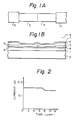
- FIGS 1A and 1B show a schematic plane view and a schematic cross-sectional view, respectively, of a base plate provided with an electro-thermal conversion element used in a liquid injection recording head to which the system of the present invention is applied.
- the electro-thermal conversion element of the present embodiment is one provided by forming a layer 3 of resistance material HfB2 having a thickness of 0.13 ⁇ m on a substrate 2 (a support member) of Si provided with a surface layer 1 of oxide SiO2 (which is not always necessary) having a thickness of about 5 ⁇ m as a heat accumulating layer, by sputtering, thereafter removing a part of the HfB2 layer 3 by etching, forming a layer 4 of resistance material V8C7 having a thickness of 0.13 ⁇ m by sputtering and forming Al layers (electrodes) 5 having a thickness of 0.5 ⁇ m by the EB (electron beam) evaporation method, thereafter effecting the
- the size of the above-mentioned layer of resistance material which generates heat when an electric power is supplied thereto is such that the width is 30 ⁇ m and the length (the direction in which an electric current flows) is 140 ⁇ m, and the left half layer 3 of resistance material as viewed in Figure 1 is constructed of HfB2 and the right half layer 4 of resistance material is constructed of V8C7 which is one of substances whose electrical resistance is varied by phase transition as will be described later.
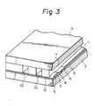
- V8C7 causes phase transition at a temperature of 1123°C and its specific electrical resistance varies from 115 ⁇ cm (below 1123°C) to 135 ⁇ cm (above 1123°C). It is because the temperature of the layer 4 of resistance material V8C7 exceeded 1123°C due to the temperature rise resulting from heating and the layer 4 of V8C7 caused phase transition that in Figure 2, the current value is low in the vicinity of the lapse of 8 ⁇ sec. after heating. Also, it is because a finite time is taken for the phase transition that the then variation in the current value is gentle.
- the specific electrical resistance of the layer 3 of resistance material HfB2 in the present embodiment was 250 ⁇ cm, and the resistances R1 and R2 were R1 > R2. Accordingly, from equations (2) and (3) above, Q1 > Q2, but the amount of generated heat Q1 per unit time of the layer 3 of resistance material HfB2 decreases and the amount of generated heat Q2 per unit time of the layer 4 of resistance material V8C7 increases when the resistance R2 of the layer 4 of resistance material V8C7 rises. That is, with the lapse of 8 ⁇ sec. after heating as the boundary, the former amount of generated heat Q1 decreased and the latter amount of generated heat Q2 increased.
- phase transition only one kind of substance has made phase transition, but harmonious recording of multi-value could be accomplished by using a plurality of substances which make phase transition (such as, for example, V6C5 and Ta).
- resistance materials may be arranged in parallel or in any combination of series and parallel.
- phase transition besides the method of increasing temperature, a method of varying any strength-indicative state parameter (such as pressure, magnetic field or chemical potential) can be used.
- any strength-indicative state parameter such as pressure, magnetic field or chemical potential
- the reference numeral 2 designates a support member
- the reference numerals 3 and 4 denote layers of resistance material
- the reference numeral 5 designates electrodes
- the reference numeral 6 denotes an insulating layer
- the reference numeral 7 designates a protective layer
- the reference numeral 9 denotes a top plate
- the reference numeral 10 designates discharge ports
- the reference numeral 11 denote a heat-acting zone.
- the layers 3 and 4 of resistance material have been provided on the support member 2 and the electrodes have been provided on the layers 3 and 4 of resistance material.
- the insulating layer 6 as a protective layer for preventing entry of liquid has been provided between the electrodes 5 of the layers 3 and 4 of resistance material and on at least a portion of each electrode 5, and the protective layer 7 has been further provided on the insulating layer 6.
- the electro-thermal conversion element has at least the layers of resistance material and the electrodes, and the protective layer 7 need not always be provided if the layers of resistance material and/or the electrodes have sufficient corrosion resistance to liquid and have resistance to mechanical damages caused by the cavitation during the extinction of bubbles.
- the insulating layer 6 need not always be provided if the liquid has a necessary resistance value.
- walls 12 have been formed on the base plate so as to partition the electro-thermal conversion element provided on the support member 2, and the top plate 11 has been further provided on the walls 12 to form the heat acting zone 11 and the discharge ports 10 communicating with the heat-acting zone 11.
- the surface layer of oxide is not shown.
- the heat-acting zone 11 is an area including a portion in which the heat energy generated by the electro-thermal conversion element acts on the liquid (ink) introduced into the recording head, and approximately, it is a liquid path (an area into which the liquid is introdued) corresponding to the upper area between the electrodes connected to the layers of resistance material.
- the liquid injection recording head thus constructed is driven in a block diagram as shown, for example, in Figure 5.
- an image siganl 501 is input to a discharge signal generator 502 and a signal corresponding to the image signal 501 is input to a discharge controller 504.
- the discharge controller 504 is connected to a power supply 503 and inputs a signal corresponding to the image signal to a recording head 505, thereby effecting recording.
- the functions of the discharge signal generator 502, the discharge controller 504 and the power supply 503 are generically named drive means.
- Figure 4 shows a schematic perspective view of an apparatus having the liquid injection recording head of the present invention (not shown).
- the reference numeral 401 designates an apparatus body cover
- the reference numeral 402 denotes an operating panel on which is provided a switch and/or a diplay device connected to various control mechanisms for controlling the apparatus.
- the liquid injection recording head of the present invention is covered with the apparatus body cover 401.
- This recording apparatus is the same as the generally known recording apparatus in that a recording member is disposed in opposed relationship with the orifice of the recording head.
- the recording head of the present invention disposed in such a recording apparatus could always accomplish recording of high accuracy and high quality even when the recording operation was performed for a long time.
- the electro-thermal conversion element is constructed with a substance which causes phase trnasition being used for a portion thereof, and this leads to the obtainment of the effect that harmonious recording can be accomplished by simple wiring.
- a substance whose electrical resistance is varied by phase transition is used for a portion of the electro-thermal conversion element and harmonious recording is effected by the utilization of the phase transition characteristic of the substance.
Abstract
Description
- This invention relates to a liquid injection recording system in which the bubbling of liquid caused by the power supply for heating of an electro-thermal conversion element is utilized to form flying liquid droplets and the liquid droplets are discharged to a recording medium to thereby accomplish recording of information such as characters, and also relates to a liquid injection recording head, a base plate for the recording head, and a recording apparatus having the liquid injection recording head.
- In the liquid injection recording system of this type utilizing heat energy, as the technique for accomplishing smooth harmonious recording over a wider range, there are generally known a technique whereby a heat generation gradient is caused in an electro-thermal conversion element (Japanese Laid-Open Patent Application No. 132258/1980 (U.S. Patent No. 4,339,762)) and a technique which uses a plurality of electro-thermal conversion elements to which signals can be independently input (Japanese Laid-Open Patent Application No. 132259/1980).
- The former harmonious recording system in which a heat generation gradient is caused in an electro-thermal conversion element can provide analog harmony in which the amount of liquid injected can be continuously freely changed by continuously changing the driving voltage or the drive pulse width. Accordingly, this system has the advantage that it can provide abundant harmony while, on the other hand, it has sometimes suffered from the problem peculiar to the analog system that the amount of liquid injected is varied under the influence of even a slight change in temperature and other external conditions.
- In contrast, the latter harmonious recording system using a plurality of electro-thermal conversion elements to which signals can be independently input is a digital harmonious system and therefore, it is difficult for such system to be affected by external factors such as temperature,etc., but to make the harmoniousness abundant, a number of independent electro-thermal conversion elements must be provided, and this has led to the problem that electrical wiring becomes very complex.
- In view of the above-noted problems, it is an object of the present invention to provide a liquid injection recording system which eliminates the complexity of the wiring which poses a problem when digital harmonious recording is to be realized.
- It is another object of the present invention to provide a liquid injection recording system in which an electrical signal is input to an electro-thermal conversion element to cause it to generate heat and produce bubbles in liquid and the liquid is injected by the action of said bubbles, characterized in that a substance whose electrical resistance is varied by phase transition is used for a portion of said electro-thermal conversion element and harmonious recording is effected by the utilization of the phase transition characteristic of said substance.
- It is still another object of the present invention to provide a liquid injection recording head provided with a base plate having an electro-thermal conversion element provided with a resistance material provided on a support member and a set of electrodes electrically connected to said resistance material and disposed at an interval, a heat-acting zone including a portion in which heat energy generated by said electro-thermal conversion element acts on liquid, and a discharge port which is a portion which is communicated with said heat-acting zone and through which the liquid is discharged by the action of said heat energy, characterized in that at least a part of said resistance material consists of a substance whose electrical resistance is varied by phase transition.
- It is yet still another object of the present invention to provide a base plate for a liquid injection recording head having an electro-thermal conversion element provided with a resistance material provided on a support member and a set of electrodes electrically connected to said resistance material and disposed at an interval, characterized in that at least a part of said resistance material consists of a substance whose electrical resistance is varied by phase transition.
- It is a further object of the present invention to provide a recording apparatus having a liquid injection recording head provided with a base plate having an electro-thermal conversion element provided with a resistance material provided on a support member and a set of electrodes electrically connected to said resistance material and disposed at an interval, a heat-acting zone including a portion in which heat energy generated by said electro-thermal conversion element acts on liquid, and a discharge port which is a portion which is communicated with said heat-acting zone and through which the liquid is discharged by the action of said heat energy, and drive means for driving said recording head, characterized in that at least a part of said resistance material consists of a substance whose electrical resistance is varied by phase transition.
- In the present invention, a substance whose electrical resistance is varied by phase transition is used for at least a part of the electro-thermal conversion element and therefore, the amount of heat generated in the portion which has caused phase transition is varied by the variation in the electrical resistance based on the phase transition and the volume of bubbles generated is varied and thus, the amount of liquid injected becomes variable, whereby harmonious recording by digital harmony abundant in harmoniousness can be accomplisehd without complicating the wiring.
-
- Figures 1A and 1B are a plan view and a cross-sectional view, respectively, showing the construction of an embodiment of the present invention.
- Figure 2 is a graph showing the relation between the variations in time and current in the embodiment of Figures 1A and 1B.
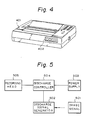
- Figure 3 is a schematic perspective view for illustrating a preferred embodiment of the liquid injection recording head of the present invention.
- Figure 4 is a schematic perspective view for illustrating a recording apparatus having the liquid injection recording head of the present invention.
- Figure 5 illustrates a preferred embodiment of a block diagram for driving the liquid injection recording head of the present invention.
- An embodiment of the present invention will hereinafter be described in detail with reference to the drawings.
- Figures 1A and 1B show a schematic plane view and a schematic cross-sectional view, respectively, of a base plate provided with an electro-thermal conversion element used in a liquid injection recording head to which the system of the present invention is applied. As shown in Figures 1A and 1B, the electro-thermal conversion element of the present embodiment is one provided by forming a
layer 3 of resistance material HfB₂ having a thickness of 0.13 µm on a substrate 2 (a support member) of Si provided with a surface layer 1 of oxide SiO₂ (which is not always necessary) having a thickness of about 5 µm as a heat accumulating layer, by sputtering, thereafter removing a part of theHfB₂ layer 3 by etching, forming alayer 4 of resistance material V₈C₇ having a thickness of 0.13 µm by sputtering and forming Al layers (electrodes) 5 having a thickness of 0.5 µm by the EB (electron beam) evaporation method, thereafter effecting the patterning by etching, and thereafter forming aninsulating layer 6 of SiO₂ having a thickness of 1.9 µm and aprotective layer 7 of Ta having a thickness of 0.55 µm by sputtering. Liquid such as ink is directed to a portion designated by 8 on theprotective layer 7. - The size of the above-mentioned layer of resistance material which generates heat when an electric power is supplied thereto is such that the width is 30 µm and the length (the direction in which an electric current flows) is 140 µm, and the
left half layer 3 of resistance material as viewed in Figure 1 is constructed of HfB₂ and theright half layer 4 of resistance material is constructed of V₈C₇ which is one of substances whose electrical resistance is varied by phase transition as will be described later. - When a rectangular pulse of
heating pulse width 12 µsec., voltage 20V and frequency 1KHz was applied between theelectrodes 5 of Figures 1A and 1B and the electric current flowing therethrough was measured, there was obtained a result as shown in Figure 2. - It is generally known that V₈C₇ causes phase transition at a temperature of 1123°C and its specific electrical resistance varies from 115 µΩcm (below 1123°C) to 135 µΩcm (above 1123°C). It is because the temperature of the
layer 4 of resistance material V₈C₇ exceeded 1123°C due to the temperature rise resulting from heating and thelayer 4 of V₈C₇ caused phase transition that in Figure 2, the current value is low in the vicinity of the lapse of 8 µsec. after heating. Also, it is because a finite time is taken for the phase transition that the then variation in the current value is gentle. - If the resistance of the
Al electrodes 5 is Rc and the resistance of thelayer 3 of resistance material HfB₂ is R₁ and the resistance of thelayer 4 of resistance material V₈C₇ is R₂, the current I flowing to theresistance materials 
- Accordingly, if the amounts of heat per unit time generated in the
layer 3 of resistance material HfB₂ and thelayer 4 of resistance material V₈C₇ are Q₁ and Q₂, respectivley, Q₁ and Q₂ are given by the following equations (2) and (3), respectively:
- The specific electrical resistance of the
layer 3 of resistance material HfB₂ in the present embodiment was 250 µΩcm, and the resistances R₁ and R₂ were R₁ > R₂. Accordingly, from equations (2) and (3) above, Q₁ > Q₂, but the amount of generated heat Q₁ per unit time of thelayer 3 of resistance material HfB₂ decreases and the amount of generated heat Q₂ per unit time of thelayer 4 of resistance material V₈C₇ increases when the resistance R₂ of thelayer 4 of resistance material V₈C₇ rises. That is, with the lapse of 8 µsec. after heating as the boundary, the former amount of generated heat Q₁ decreased and the latter amount of generated heat Q₂ increased. - By thus changing the heating pulse width applied between the
electrodes 5 by the use of the electro-thermal conversion element as shown in Figure 1, harmonious recording which varies smoothly has become possible. That is, it has been confirmed that when the heating pulse width is 6 µsec., only that portion ofliquid 8 which is above thelayer 3 of resistance material HfB₂ is foamed and when the heating pulse width is 12 µsec., that portion of the liquid which is above both of thelayer 3 of resistance material HfB₂ and thelayer 4 of resistance material V₈C₇ is foamed. The then amount of discharged liquid is shown in Table 1 below.
- In the above-described embodiment, only one kind of substance has made phase transition, but harmonious recording of multi-value could be accomplished by using a plurality of substances which make phase transition (such as, for example, V₆C₅ and Ta).
- It is not always necessary to arrange a plurality of resistance materials in series, but the resistance materials may be arranged in parallel or in any combination of series and parallel.
- Also, to cause phase transition, besides the method of increasing temperature, a method of varying any strength-indicative state parameter (such as pressure, magnetic field or chemical potential) can be used.
- Of course, the present invention is not restricted to the above-described embodiment, but is usable for various modifications as far as they do not depart from the subject of the present invention.
- A preferred example of the liquid injection recording head used in the present embodiment will now be described with reference to Figure 3.
- In Figure 3 the
reference numeral 2 designates a support member, thereference numerals reference numeral 5 designates electrodes, thereference numeral 6 denotes an insulating layer, thereference numeral 7 designates a protective layer, thereference numeral 9 denotes a top plate, thereference numeral 10 designates discharge ports, and thereference numeral 11 denote a heat-acting zone. - As shown, the
layers support member 2 and the electrodes have been provided on thelayers insulating layer 6 as a protective layer for preventing entry of liquid has been provided between theelectrodes 5 of thelayers electrode 5, and theprotective layer 7 has been further provided on theinsulating layer 6. The electro-thermal conversion element has at least the layers of resistance material and the electrodes, and theprotective layer 7 need not always be provided if the layers of resistance material and/or the electrodes have sufficient corrosion resistance to liquid and have resistance to mechanical damages caused by the cavitation during the extinction of bubbles. Likewise, theinsulating layer 6 need not always be provided if the liquid has a necessary resistance value. - In Figure 3,
walls 12 have been formed on the base plate so as to partition the electro-thermal conversion element provided on thesupport member 2, and thetop plate 11 has been further provided on thewalls 12 to form theheat acting zone 11 and thedischarge ports 10 communicating with the heat-actingzone 11. (In Figure 3, the surface layer of oxide is not shown.) - The heat-acting
zone 11 is an area including a portion in which the heat energy generated by the electro-thermal conversion element acts on the liquid (ink) introduced into the recording head, and approximately, it is a liquid path (an area into which the liquid is introdued) corresponding to the upper area between the electrodes connected to the layers of resistance material. - The liquid injection recording head thus constructed is driven in a block diagram as shown, for example, in Figure 5.
- That is, an
image siganl 501 is input to adischarge signal generator 502 and a signal corresponding to theimage signal 501 is input to adischarge controller 504. Thedischarge controller 504 is connected to apower supply 503 and inputs a signal corresponding to the image signal to arecording head 505, thereby effecting recording. In the present invention, the functions of thedischarge signal generator 502, thedischarge controller 504 and thepower supply 503 are generically named drive means. - Figure 4 shows a schematic perspective view of an apparatus having the liquid injection recording head of the present invention (not shown).
- In Figure 4, the
reference numeral 401 designates an apparatus body cover, and thereference numeral 402 denotes an operating panel on which is provided a switch and/or a diplay device connected to various control mechanisms for controlling the apparatus. - The liquid injection recording head of the present invention is covered with the
apparatus body cover 401. This recording apparatus is the same as the generally known recording apparatus in that a recording member is disposed in opposed relationship with the orifice of the recording head. - The recording head of the present invention disposed in such a recording apparatus could always accomplish recording of high accuracy and high quality even when the recording operation was performed for a long time.
- As described above, according to the present invention, the electro-thermal conversion element is constructed with a substance which causes phase trnasition being used for a portion thereof, and this leads to the obtainment of the effect that harmonious recording can be accomplished by simple wiring.
- In a liquid injection recording system wherein an electrical signal is input to an electro-thermal conversion element to cause it to generate heat and produce bubbles in liquid and the liquid is injected by the action of the bubbles, a substance whose electrical resistance is varied by phase transition is used for a portion of the electro-thermal conversion element and harmonious recording is effected by the utilization of the phase transition characteristic of the substance.
Claims (17)
Applications Claiming Priority (2)
| Application Number | Priority Date | Filing Date | Title |
|---|---|---|---|
| JP61265649A JPS63120656A (en) | 1986-11-10 | 1986-11-10 | Liquid jet recording system |
| JP265649/86 | 1986-11-10 |
Publications (3)
| Publication Number | Publication Date |
|---|---|
| EP0267567A2 true EP0267567A2 (en) | 1988-05-18 |
| EP0267567A3 EP0267567A3 (en) | 1989-07-26 |
| EP0267567B1 EP0267567B1 (en) | 1992-03-25 |
Family
ID=17420069
Family Applications (1)
| Application Number | Title | Priority Date | Filing Date |
|---|---|---|---|
| EP87116527A Expired EP0267567B1 (en) | 1986-11-10 | 1987-11-09 | A liquid injection recording system, a liquid injection recording head, a base plate for the recording head, and a recording apparatus having the liquid injection recording head |
Country Status (4)
| Country | Link |
|---|---|
| US (1) | US4831391A (en) |
| EP (1) | EP0267567B1 (en) |
| JP (1) | JPS63120656A (en) |
| DE (1) | DE3777758D1 (en) |
Cited By (4)
| Publication number | Priority date | Publication date | Assignee | Title |
|---|---|---|---|---|
| EP0294631A2 (en) * | 1987-06-12 | 1988-12-14 | Lexmark International, Inc. | A thermal drop-on-demand ink jet print head |
| EP0352978A2 (en) * | 1988-07-28 | 1990-01-31 | Lexmark International, Inc. | A thermal drop-on-demand ink jet print head |
| EP0396315A1 (en) * | 1989-05-01 | 1990-11-07 | Xerox Corporation | Thermal ink jet printhead with bubble generating heating elements |
| EP0451778A2 (en) * | 1990-04-09 | 1991-10-16 | Seiko Instruments Inc. | Driving method for thermal printer element |
Families Citing this family (5)
| Publication number | Priority date | Publication date | Assignee | Title |
|---|---|---|---|---|
| US4935752A (en) * | 1989-03-30 | 1990-06-19 | Xerox Corporation | Thermal ink jet device with improved heating elements |
| GB2240951B (en) * | 1990-02-09 | 1994-10-05 | Canon Kk | Ink jet recording system |
| JP3652016B2 (en) | 1996-07-12 | 2005-05-25 | キヤノン株式会社 | Liquid discharge head and liquid discharge method |
| US5901425A (en) | 1996-08-27 | 1999-05-11 | Topaz Technologies Inc. | Inkjet print head apparatus |
| US6799838B2 (en) | 1998-08-31 | 2004-10-05 | Canon Kabushiki Kaisha | Liquid discharge head liquid discharge method and liquid discharge apparatus |
Citations (2)
| Publication number | Priority date | Publication date | Assignee | Title |
|---|---|---|---|---|
| US4339762A (en) * | 1979-04-02 | 1982-07-13 | Canon Kabushiki Kaisha | Liquid jet recording method |
| GB2159465A (en) * | 1984-05-25 | 1985-12-04 | Canon Kk | Generating droplets by heating |
Family Cites Families (4)
| Publication number | Priority date | Publication date | Assignee | Title |
|---|---|---|---|---|
| US4296309A (en) * | 1977-05-19 | 1981-10-20 | Canon Kabushiki Kaisha | Thermal head |
| JPS55132259A (en) * | 1979-04-02 | 1980-10-14 | Canon Inc | Liquid jet recording method |
| JPS5833472A (en) * | 1981-08-24 | 1983-02-26 | Canon Inc | Liquid jet recording head |
| JPS59106974A (en) * | 1982-12-11 | 1984-06-20 | Canon Inc | Liquid jet recording head |
-
1986
- 1986-11-10 JP JP61265649A patent/JPS63120656A/en active Pending
-
1987
- 1987-11-09 EP EP87116527A patent/EP0267567B1/en not_active Expired
- 1987-11-09 DE DE8787116527T patent/DE3777758D1/en not_active Expired - Lifetime
-
1988
- 1988-08-25 US US07/236,290 patent/US4831391A/en not_active Expired - Lifetime
Patent Citations (2)
| Publication number | Priority date | Publication date | Assignee | Title |
|---|---|---|---|---|
| US4339762A (en) * | 1979-04-02 | 1982-07-13 | Canon Kabushiki Kaisha | Liquid jet recording method |
| GB2159465A (en) * | 1984-05-25 | 1985-12-04 | Canon Kk | Generating droplets by heating |
Cited By (8)
| Publication number | Priority date | Publication date | Assignee | Title |
|---|---|---|---|---|
| EP0294631A2 (en) * | 1987-06-12 | 1988-12-14 | Lexmark International, Inc. | A thermal drop-on-demand ink jet print head |
| EP0294631A3 (en) * | 1987-06-12 | 1989-11-29 | International Business Machines Corporation | A thermal drop-on-demand ink jet print head |
| EP0352978A2 (en) * | 1988-07-28 | 1990-01-31 | Lexmark International, Inc. | A thermal drop-on-demand ink jet print head |
| EP0352978A3 (en) * | 1988-07-28 | 1990-07-18 | Lexmark International, Inc. | A thermal drop-on-demand ink jet print head |
| EP0396315A1 (en) * | 1989-05-01 | 1990-11-07 | Xerox Corporation | Thermal ink jet printhead with bubble generating heating elements |
| EP0451778A2 (en) * | 1990-04-09 | 1991-10-16 | Seiko Instruments Inc. | Driving method for thermal printer element |
| EP0451778A3 (en) * | 1990-04-09 | 1992-01-22 | Seiko Instruments Inc. | Driving method for thermal printer element |
| US5359352A (en) * | 1990-04-09 | 1994-10-25 | Seiko Instruments Inc. | Driving method of heat generating resistor in heat recording device |
Also Published As
| Publication number | Publication date |
|---|---|
| EP0267567A3 (en) | 1989-07-26 |
| EP0267567B1 (en) | 1992-03-25 |
| US4831391A (en) | 1989-05-16 |
| JPS63120656A (en) | 1988-05-25 |
| DE3777758D1 (en) | 1992-04-30 |
Similar Documents
| Publication | Publication Date | Title |
|---|---|---|
| US4458256A (en) | Ink jet recording apparatus | |
| US5446484A (en) | Thin-film transducer ink jet head | |
| US4339762A (en) | Liquid jet recording method | |
| US4313124A (en) | Liquid jet recording process and liquid jet recording head | |
| EP0267567A2 (en) | A liquid injection recording system, a liquid injection recording head, a base plate for the recording head, and a recording apparatus having the liquid injection recording head | |
| US5481287A (en) | Liquid jet recording head having a plurality of heating elements and liquid jet recording apparatus having the same | |
| KR100236149B1 (en) | Ink jet recording device and method of producing the same | |
| WO1999022938A1 (en) | Ink jet printer | |
| EP0370765B1 (en) | Ink jet head cartridge with a residual-ink detector | |
| US4907020A (en) | Driving circuit for an ink jet recording head having resistor elements respectively connected parallel to the electrothermal converting elements | |
| US6499833B2 (en) | Ink jet recording head and ink jet recording apparatus | |
| EP1322475B1 (en) | Droplet deposition apparatus | |
| US4074280A (en) | Thermal recording apparatus | |
| JP2658020B2 (en) | Ink jet recording device | |
| EP0813969B1 (en) | Method of producing a record head for an electrostatic ink jet recorder | |
| EP1180433B1 (en) | Ink jet recording head, ink jet recording apparatus and ink jet recording method | |
| JPH0551461B2 (en) | ||
| US5781211A (en) | Ink jet recording head apparatus | |
| JP2505900B2 (en) | Ink jet recording head | |
| US4972202A (en) | Method for driving liquid-jet recorder | |
| JPH0717065B2 (en) | Inkjet recording device | |
| JPH0532221B2 (en) | ||
| JPS59124867A (en) | Liquid jetting recorder | |
| JPH02150359A (en) | Ink jet recorder | |
| JPS59124871A (en) | Liquid jet recorder |
Legal Events
| Date | Code | Title | Description |
|---|---|---|---|
| PUAI | Public reference made under article 153(3) epc to a published international application that has entered the european phase |
Free format text: ORIGINAL CODE: 0009012 |
|
| AK | Designated contracting states |
Kind code of ref document: A2 Designated state(s): DE FR GB IT |
|
| PUAL | Search report despatched |
Free format text: ORIGINAL CODE: 0009013 |
|
| AK | Designated contracting states |
Kind code of ref document: A3 Designated state(s): DE FR GB IT |
|
| 17P | Request for examination filed |
Effective date: 19891212 |
|
| 17Q | First examination report despatched |
Effective date: 19910503 |
|
| GRAA | (expected) grant |
Free format text: ORIGINAL CODE: 0009210 |
|
| AK | Designated contracting states |
Kind code of ref document: B1 Designated state(s): DE FR GB IT |
|
| REF | Corresponds to: |
Ref document number: 3777758 Country of ref document: DE Date of ref document: 19920430 |
|
| ITF | It: translation for a ep patent filed |
Owner name: SOCIETA' ITALIANA BREVETTI S.P.A. |
|
| ET | Fr: translation filed | ||
| PLBE | No opposition filed within time limit |
Free format text: ORIGINAL CODE: 0009261 |
|
| STAA | Information on the status of an ep patent application or granted ep patent |
Free format text: STATUS: NO OPPOSITION FILED WITHIN TIME LIMIT |
|
| 26N | No opposition filed | ||
| REG | Reference to a national code |
Ref country code: GB Ref legal event code: IF02 |
|
| PGFP | Annual fee paid to national office [announced via postgrant information from national office to epo] |
Ref country code: DE Payment date: 20051103 Year of fee payment: 19 |
|
| PGFP | Annual fee paid to national office [announced via postgrant information from national office to epo] |
Ref country code: FR Payment date: 20051108 Year of fee payment: 19 |
|
| PGFP | Annual fee paid to national office [announced via postgrant information from national office to epo] |
Ref country code: GB Payment date: 20051109 Year of fee payment: 19 |
|
| PGFP | Annual fee paid to national office [announced via postgrant information from national office to epo] |
Ref country code: IT Payment date: 20061130 Year of fee payment: 20 |
|
| PG25 | Lapsed in a contracting state [announced via postgrant information from national office to epo] |
Ref country code: DE Free format text: LAPSE BECAUSE OF NON-PAYMENT OF DUE FEES Effective date: 20070601 |
|
| GBPC | Gb: european patent ceased through non-payment of renewal fee |
Effective date: 20061109 |
|
| REG | Reference to a national code |
Ref country code: FR Ref legal event code: ST Effective date: 20070731 |
|
| PG25 | Lapsed in a contracting state [announced via postgrant information from national office to epo] |
Ref country code: GB Free format text: LAPSE BECAUSE OF NON-PAYMENT OF DUE FEES Effective date: 20061109 |
|
| PG25 | Lapsed in a contracting state [announced via postgrant information from national office to epo] |
Ref country code: FR Free format text: LAPSE BECAUSE OF NON-PAYMENT OF DUE FEES Effective date: 20061130 |