EP0266864B1 - Cutting tool for cutting well casing - Google Patents
Cutting tool for cutting well casing Download PDFInfo
- Publication number
- EP0266864B1 EP0266864B1 EP87307098A EP87307098A EP0266864B1 EP 0266864 B1 EP0266864 B1 EP 0266864B1 EP 87307098 A EP87307098 A EP 87307098A EP 87307098 A EP87307098 A EP 87307098A EP 0266864 B1 EP0266864 B1 EP 0266864B1
- Authority
- EP
- European Patent Office
- Prior art keywords
- cutting
- arm
- cutting tool
- blade
- casing
- Prior art date
- Legal status (The legal status is an assumption and is not a legal conclusion. Google has not performed a legal analysis and makes no representation as to the accuracy of the status listed.)
- Expired - Lifetime
Links
- 238000005520 cutting process Methods 0.000 title claims description 225
- 239000012530 fluid Substances 0.000 claims description 27
- 230000002093 peripheral effect Effects 0.000 claims description 6
- 239000000463 material Substances 0.000 claims description 5
- 238000003801 milling Methods 0.000 description 13
- 238000005553 drilling Methods 0.000 description 7
- 230000002441 reversible effect Effects 0.000 description 4
- 230000006978 adaptation Effects 0.000 description 2
- 238000005219 brazing Methods 0.000 description 2
- 230000003247 decreasing effect Effects 0.000 description 2
- 238000012986 modification Methods 0.000 description 2
- 230000004048 modification Effects 0.000 description 2
- 229910001209 Low-carbon steel Inorganic materials 0.000 description 1
- 239000012634 fragment Substances 0.000 description 1
- 239000011159 matrix material Substances 0.000 description 1
- 238000000034 method Methods 0.000 description 1
- MOFOBJHOKRNACT-UHFFFAOYSA-N nickel silver Chemical compound [Ni].[Ag] MOFOBJHOKRNACT-UHFFFAOYSA-N 0.000 description 1
- 239000010956 nickel silver Substances 0.000 description 1
- 229940100890 silver compound Drugs 0.000 description 1
- 238000007514 turning Methods 0.000 description 1
- 239000011800 void material Substances 0.000 description 1
Images


Classifications
-
- B—PERFORMING OPERATIONS; TRANSPORTING
- B23—MACHINE TOOLS; METAL-WORKING NOT OTHERWISE PROVIDED FOR
- B23B—TURNING; BORING
- B23B5/00—Turning-machines or devices specially adapted for particular work; Accessories specially adapted therefor
- B23B5/16—Turning-machines or devices specially adapted for particular work; Accessories specially adapted therefor for bevelling, chamfering, or deburring the ends of bars or tubes
- B23B5/167—Tools for chamfering the ends of bars or tubes
- B23B5/168—Tools for chamfering the ends of bars or tubes with guiding devices
-
- E—FIXED CONSTRUCTIONS
- E21—EARTH DRILLING; MINING
- E21B—EARTH DRILLING, e.g. DEEP DRILLING; OBTAINING OIL, GAS, WATER, SOLUBLE OR MELTABLE MATERIALS OR A SLURRY OF MINERALS FROM WELLS
- E21B10/00—Drill bits
- E21B10/26—Drill bits with leading portion, i.e. drill bits with a pilot cutter; Drill bits for enlarging the borehole, e.g. reamers
- E21B10/32—Drill bits with leading portion, i.e. drill bits with a pilot cutter; Drill bits for enlarging the borehole, e.g. reamers with expansible cutting tools
- E21B10/322—Drill bits with leading portion, i.e. drill bits with a pilot cutter; Drill bits for enlarging the borehole, e.g. reamers with expansible cutting tools cutter shifted by fluid pressure
-
- E—FIXED CONSTRUCTIONS
- E21—EARTH DRILLING; MINING
- E21B—EARTH DRILLING, e.g. DEEP DRILLING; OBTAINING OIL, GAS, WATER, SOLUBLE OR MELTABLE MATERIALS OR A SLURRY OF MINERALS FROM WELLS
- E21B29/00—Cutting or destroying pipes, packers, plugs, or wire lines, located in boreholes or wells, e.g. cutting of damaged pipes, of windows; Deforming of pipes in boreholes or wells; Reconditioning of well casings while in the ground
- E21B29/002—Cutting, e.g. milling, a pipe with a cutter rotating along the circumference of the pipe
- E21B29/005—Cutting, e.g. milling, a pipe with a cutter rotating along the circumference of the pipe with a radially-expansible cutter rotating inside the pipe, e.g. for cutting an annular window
-
- E—FIXED CONSTRUCTIONS
- E21—EARTH DRILLING; MINING
- E21B—EARTH DRILLING, e.g. DEEP DRILLING; OBTAINING OIL, GAS, WATER, SOLUBLE OR MELTABLE MATERIALS OR A SLURRY OF MINERALS FROM WELLS
- E21B29/00—Cutting or destroying pipes, packers, plugs, or wire lines, located in boreholes or wells, e.g. cutting of damaged pipes, of windows; Deforming of pipes in boreholes or wells; Reconditioning of well casings while in the ground
- E21B29/06—Cutting windows, e.g. directional window cutters for whipstock operations
-
- Y—GENERAL TAGGING OF NEW TECHNOLOGICAL DEVELOPMENTS; GENERAL TAGGING OF CROSS-SECTIONAL TECHNOLOGIES SPANNING OVER SEVERAL SECTIONS OF THE IPC; TECHNICAL SUBJECTS COVERED BY FORMER USPC CROSS-REFERENCE ART COLLECTIONS [XRACs] AND DIGESTS
- Y10—TECHNICAL SUBJECTS COVERED BY FORMER USPC
- Y10T—TECHNICAL SUBJECTS COVERED BY FORMER US CLASSIFICATION
- Y10T408/00—Cutting by use of rotating axially moving tool
- Y10T408/81—Tool having crystalline cutting edge
-
- Y—GENERAL TAGGING OF NEW TECHNOLOGICAL DEVELOPMENTS; GENERAL TAGGING OF CROSS-SECTIONAL TECHNOLOGIES SPANNING OVER SEVERAL SECTIONS OF THE IPC; TECHNICAL SUBJECTS COVERED BY FORMER USPC CROSS-REFERENCE ART COLLECTIONS [XRACs] AND DIGESTS
- Y10—TECHNICAL SUBJECTS COVERED BY FORMER USPC
- Y10T—TECHNICAL SUBJECTS COVERED BY FORMER US CLASSIFICATION
- Y10T408/00—Cutting by use of rotating axially moving tool
- Y10T408/83—Tool-support with means to move Tool relative to tool-support
- Y10T408/85—Tool-support with means to move Tool relative to tool-support to move radially
- Y10T408/858—Moving means including wedge, screw or cam
- Y10T408/8595—Pivotable tool-support
-
- Y—GENERAL TAGGING OF NEW TECHNOLOGICAL DEVELOPMENTS; GENERAL TAGGING OF CROSS-SECTIONAL TECHNOLOGIES SPANNING OVER SEVERAL SECTIONS OF THE IPC; TECHNICAL SUBJECTS COVERED BY FORMER USPC CROSS-REFERENCE ART COLLECTIONS [XRACs] AND DIGESTS
- Y10—TECHNICAL SUBJECTS COVERED BY FORMER USPC
- Y10T—TECHNICAL SUBJECTS COVERED BY FORMER US CLASSIFICATION
- Y10T82/00—Turning
- Y10T82/12—Radially moving rotating tool inside bore
- Y10T82/125—Tool simultaneously moving axially
- Y10T82/128—Pivoted to tool-carrier
Definitions
- the invention relates generally to an improved cutting tool having radially expandable cutter arms for cutting well casing, and more particularly to improved cutting blades on the outer end of the radially expandable cutter arms for engaging the inner periphery of the well casing in cutting relation.
- Cutting tools for cutting the inner periphery of well casing and having a cutter body with cutter arms pivotally mounted within slots in the cutter body for movement in a radial direction between a retracted position for lowering the tool within the well casing, and a radially expandable extended position in cutting contact with the inner periphery of the well casing.
- the lower end portions of the cutter arms have also been formed heretofore with blades having cemented carbide cutting fragments or chips secured thereto and forming the cutting edge.
- U. S. Patent No. 3,331,439 dated July 18, 1967 shows a cutting tool having pivotally mounted cutter arms thereon with blades on the lower ends thereof formed with hard cutting material embedded therein.
- U. S. Patent No. 2,859,943 dated November 11, 1958 shows a cutting tool for well casing having pivoted outer arms with cutter blades thereon having embedded carbide cutting fragements or chips for forming the cutting surface.
- U.S. Patent No. 3,195,636 dated July 20, 1965 shows a similar cutting tool with a pivoted cutter arm and a matrix material bonded to the cutting face of the arm and having embedded cutting elements.
- Prior cutting tools such as shown in the above patents, when utilized for cutting a well casing, such as a forty-eight (48) inch (122 cm) diameter casing having a wall thickness of one and one-half (1-1/2) inch (3.8 cm), for example, have required around four or five hours in which to complete the cutting operation.
- EP-A-0231989 discloses a cutting tool which is utilized generally with milling tools for cutting and removal of casing progressively from the upper end of the casing and employs cutting blades having their lower ends tilted rearwardly relative to their upper ends in the direction of rotation. A plurality of hard carbide cutting elements are secured to the leading surfaces of the blades and form planar cutting surfaces.
- a cutting tool mounted for rotation within a well for cutting a casing therein during rotation and comprising:
- One embodiment of a cutting tool of the present invention has improved cutting blades on the outer ends of the radially expandable cutter arms with such cutting blades having a leading planar cutting surface with respect to the axis of rotation of the tool to define a cutting and/or milling edge at its radially outermost surfaces, the lower end of the leading planar cutting surface both inclined rearwardly with respect to the respective upper end of the leading planar cutting surface thereby to present an inclined cutting surface engaging the casing in cutting relation.
- the base of the blade has a plurality of hard carbide cutting elements or inserts mounted thereon in closely fitting relation to each other in a plurality of adjacent rows to form the planar cutting surface, and both the blade base and the carbide inserts are progressively worn away from their outermost surfaces as the cutting operation progresses.
- the hard carbide inserts which are of a rectangular cross section have generally parallel planar front and rear faces and the side surface between the front and rear faces are inclined with respect to the rotational axis of the cutting tool to provide a so-called negative rake thereby to increase the cutting effectiveness and efficiency of the cutting blades during the cutting operation.
- the side surfaces between the planar front and rear faces of the inserts extend at right angles or perpendicularly to the planar faces.
- the side or circumferential surface of the inserts are tilted an amount with respect to the direction of rotation the same as the amount of tilting or inclination of the planar leading surface of the blade.
- the plurality of hard carbide cutting elements such as cylindrical discs, are arranged in staggered rows on the leading face, to present a minimum bearing surface against the casing while allowing the relatively small staggered carbide discs or cutting elements to continually expose a fresh cutting edge as the cutting operation progresses thereby to perform the cutting action in a minimum of time.
- a forty-eight (48) inch (122 cm) diameter casing having a wall thickness of one and one-half (1-1/2) inches (3.8 cm) was cut in less than one hour as compared with previous cutting tools and cutting methods taking around four (4) hours or more in which to complete the cutting operation.
- One embodiment of this invention is directed to a radially expanding cutter arm having a reversible blade on its end including generally parallel planar leading surfaces so that upon wear of the leading surface, the blade may be removed from the cutter arm and reversed (rotated 180°) with the initial trailing surface then becoming the new leading surface upon reversal thereby to present a new cutting surface to the casing being cut.
- a reversible blade increases the life of the blade particularly when the blades are tilted or inclined with respect to the rotational axis of the cutting tool.
- Another embodiment of this invention provides an improved cutting blade having a plurality of hard carbide cutting elemtns or inserts mounted in closely fitting relation to each other in adjacent rows on the leading face of the blade to form a leading planar cutting surface.
- the inserts have generally parallel planar front and rear faces with their rear faces secured to a blade base and their front faces forming the planar cutting surface.
- the circumferential side surface of the inserts between the parallel faces extends along a longitudinal axis generally at right angles to the planar cutting surface and being of a relatively small diameter thereby to continually present sharp edges from adjacent successive carbide inserts as the carbide inserts are progressively worn away from their radially outermost surfaces as the cutting operation continues.
- the hard carbide inserts are secured such as by brazing to the adjacent surface of the blade and form the cutting edge which digs or bites into the inner peripheral surface of the surrounding casing to be cut.
- a well casing is shown at 10.
- a drill string is indicated generally at 12 and has its lower threaded end 14 in threaded engagement with the upper end of an upper sub 16 defining a central bore 18 to receive drilling fluid through drill string 12 from a surface location.
- a lower threaded end 20 of upper sub 16 is received in threaded engagement within the upper end of a cutting tool generally indicated at 22.
- Cutting tool 22 has a tubular cutter body 24 forming a central bore 26 in which fluid pressure responsive means indicated generally at 28 is housed and is responsive to flowing drilling fluid from drill string 12 for hydraulic actuation as will be explained further.
- Cutting tool 22 has a lower reduced diameter portion 30 with a lower internally threaded end 32.
- Three longitudinally extending slots 34 are circumferentially spaced about the periphery of tubular cutter body 24 adjacent reduced diameter portion 30 and receive elongate cutter arms 36 of a generally rectangular cross- section having a longitudinal axis 37.
- Each elongate arm 36 has an upper end portion 38 pivotally mounted by a pin 40 to cutter body 24 and a lower downward extending end portion 42.
- a tang or extension 44 extends upwardly from upper end portion 38.
- Elongate arms 36 are free for pivoting between the retracted position shown in FIGURE 1 for lowering within casing 10, and a radially expanded or extended position as shown in FIGURE 2 in which lower end portions 42 of arms 36 are swung or moved radially outwardly into cutting contact with the periphery of casing 10 to be cut.
- Wells may have several concentric casing strings which are to be cut so that the length of arms 36 and the amount of pivotal movement is preselected depending on the number and spacing of concentric casing strings to be cut.
- the embodiment of the invention shown in FIGURES 1-10 is particularly adapted for cutting a single casing string, but the embodiment shown in FIGURES 11-13 is adapted for cutting a plurality of concentric casing strings, if desired.
- the cutting operation is normally accomplished in a single trip within the well by directing drilling fluid under pressure from the surface through well string 12 and by rotating well string 12 and cutting tool 22 with cutter arms 36 pivoted into a radially expanded position into cutting contact with the periphery of casing 10 to be cut.
- the pivotal connections between arms 36 and cutter body 24 are designed so that the connections are sufficient to transmit the torque required to accomplish the cutting of casing 10.
- fluid pressure responsive means For moving lower end portions 42 of cutter arms 36 radially outwardly into expanded cutting engagement with casing 10, fluid pressure responsive means generally indicated at 28 includes a piston 46 mounted within cutter body 24 and continuously urged upwardly by spring 48.
- a pair of spaced flow restrictions or orifice rings are provided at 50 and are sized to provide a restriction to the downward flow of drilling fluid.
- An indicator 52 adjacent upper orifice ring 50 has a plurality of ports 54 therein and when a predetermined fluid pressure differential is reached, piston 46 moves downwardly contacting tangs 44 to pivot cutter arms 36 outwardly radially into cutting engagement with casing 10.
- a decreased fluid pressure differential is indicated at the surface so that an operator is aware that cutter arms 36 are in expanded cutting engagement with the inner periphery of casing 10 to be cut.
- Cutter blade assembly 57 includes a pair of substantially identical blades 58 and 60.
- Cutter arm 36 has a pair of slots or grooves 62 and 64 formed in the end of lower end portion 42. Grooves 62 and 64 define a pair of contiguous bifurcations which form a common center prong or finger 66 and a pair of end prongs or fingers 68 and 70 on opposite sides of finger 66. Fingers 66, 68 and 70 have transversely aligned openings 72 therein.
- Blades 58 and 60 have shanks 74 received within grooves 62 and 64 and a pair of openings 76 in shanks 74 are transversely aligned with openings 72 in fingers 66, 68, and 70. Suitable nut and bolt combinations generally indicated at 78 are received within transversely aligned openings 72 and 76 for securing blades 58 and 60 within slots 62 and 64.
- Each blade 58, 60 has a base 80 having a planar front face or surface 82 and a generally parallel planar rear face or surface 84. Front surface 82 forms a leading surface facing the direction of rotation and surface 84 forms a trailing surface with respect to the direction of rotation. Blade 58 diverges from shank 74 to form a generally triangular shape as viewed in front elevation looking at planar front face 82 and has radially spaced inner and outer apices 86 and 88 defining inner and outer surfaces. The radially outermost surface formed by apex 88 defines the cutting edge engaging the inner periphery of casing 10 in cutting relation.
- blade 58 With respect to the longitudinal axis 37 of elongate arm 36, blade 58 has an upper end 58A, a lower end 58B, an inner sloping side 58C, and an outer sloping side 58D. Outer side 58D is positioned adjacent the casing 10 to be cut. Lower end 58B has a portion thereof cutaway or notched to form notched surfaces 58E.
- finger 68 defines an outer surface 68A and an inner surface 68B
- finger 70 defines outer surface 70A and inner surface 70B
- center finger 66 defines opposed surfaces 66A and 66B.
- finger 68 tapers upwardly and finger 70 tapers downwardly to provide an increased thickness of finger 68 at its lower end and a decreased thickness of finger 70 at its lower end.
- the lower end 58B of blade 58 is tilted rearwardly with respect to upper end 58A at an angle A as shown in Figure 7.
- Angle A is of an optimum around five (5) degrees with an optimum range between around one degree (1 ° ) and fifteen (15) degrees . Under certain conditions of use, an angle A as high as twenty (20) degrees will function adequately.
- Inserts or discs 90 are preferably arranged in staggered rows extending from apexes 86 and 88 with the outer two rows having, for example, seven and six discs, respectively, as shown generally in Figure 2.
- a third row has two discs 90 therein.
- a disc 90 which has been found to function in a satisfactory matter has a thickness of three sixteenths (3/16) inch (4.8 mm), a diameter of three eighths (3/8) inch (9.5 mm), and is sold under the name "Sandvik S6" by the Sandvik Company, located in Houston, Texas.
- Each cylindrical disc 90 has a front face 90A which forms a cutting face for leading face 82 and an opposed rear face 90B which is flush with supporting base 80 and brazed thereto.
- a cylindrical surface 90C connects faces 90A and 90B and extends along a line or longitudinal axis at right angles to the planar front and rear faces 90A and 90B.
- An annular cutting edge 90D formed at the juncture of front face 90A and cylindrical surface 90C digs or bites into the inner peripheral surface of casing 10 in cutting relation as shown in FIGURE 2.
- Front faces 90A of discs 90 form the leading cutting surfaces on blade 58 and extend at angle A with respect to the axis of rotation as shown in Figure 7 thereby to provide a negative rake for faces 90A and annular cutting edges 90D.
- each disc 90 has its longitudinal axis arranged at an angle B with respect to the transverse axis of elongate arm 36.
- Angle B is equal to angle A since annular surface 90C extends along a longitudinal axis at right angles to faces 90A and 90B.
- the sharp annular cutting edge 90D is presented to the inner periphery of casing 10 to be cut during the initial contact of carbide discs 90 with casing 10. It is to be understood that any void areas formed between discs 90 will be filled in during the bracing operation, such as with a nickel silver compound.
- a relatively smooth uninterrupted planar leading cutting surface is provided by the plurality of discs 90.
- a sharp edge 90D initially contacts the inner periphery of the casing to be cut.
- successive carbide discs 90 and cutting edges 90D are continually presented to the inner periphery of casing 10 since discs 90 with annular cutting edges 90D are staggered in three rows and the wear continues progressively from the radially outermost surfaces of blades 58 and 60.
- the sharp cutting edge 90D of disc 90 not the entire width of cylindrical surface 90C, is initially in contact with casing 10 since surface 90C has a negative rake as defined by angle B.
- outer side 58D of blade 58 is positioned rearwardly of inner side 58C with respect to the direction of rotation as indicated at angle C and this likewise tilts cylindrical surface 90C of disc 90 so that a greater portion of annular cutting edge 90D of disc 90 is presented at an angle with respect to casing 10.
- Angle C is preferably the same as angles A and B.
- Hard carbide disc 90 has a thickness indicated at D in Figure 6 of three-sixteenths (3/16) inch (4.8 mm),
- the thickness of base 80 of blade 58 is shown at E in FIGURE 7 and is preferably around three-eighths (3/8) inch (9.5 mm) thick or around two (2) times the thickness of disc 90.
- a thickness of base 80 from around two (2) to four (4) times the thickness of insert or disc 90 will function satisfactorily.
- the material from which blade 58 is formed is of a mild steel having a Brinell hardness range of around one hundred forty-five (145) with an optimum Brinell hardness range of between around one hundred thirty (130) and one hundred sixty (160).
- the carbide discs 90 have a Rockwell A hardness of around eighty-five (85) to eighty-eight (88) which is around seven to nine times harder than the material from which blade 58 is formed. For satisfactory results, it is believed that disc 90 should be at least around three (3) times harder than blade 58.
- Casing 10 to be cut has a Brinell hardness of around two hundred (200) and carbide discs 90 are around five (5) times harder than casing 10.
- base 80 being formed of a material several times as soft as the carbide discs 90, the wear flat surface formed as base 80 is worn away generates a minimum of friction which permits minimum torque for rotation of drill string 12 and cutting tool 22.
- the spacing indicated at F in Figure 6 between blades 58 and 60 should be an amount sufficient to receive adequately the turnings or cuttings during the cutting operation generated by forward blade 58 with respect to the axis of rotation. A spacing F of around one-half (1/2) inch (12.5 mm) has been found to function effectively.
- discs 90 are provided adjacent both inner side 58C of blade 58 as well as outer side 58D. Discs 90 adjacent inner side 58C are inoperable during the cutting operation and are used only upon reversal of blade 58 after wear of outer side 58D. Blades 58 and 60 are reversed after removal of the cutting tool 22 from the well and inner sides 58C then become outer sides 58D. Blades 58 and 60 are reversed generally after around one (1) inch of wear.
- blades 58 and 60 were arranged at angles A, B and C of around five (5) degrees.
- a torque of around five thousand (5000) foot pounds (6779 Nm) was utilized and a rotational speed of around 120 RPM was provided with fluid pressure of around 500-600 psi (3447 to 4137 KN/m 2 ).
- Test results on several different cutting operations have been obtained for cutting a forty-eight (48) inch (122 cm) diameter casing in less than one hour.
- inserts 90 have been illustrated as cylindrical discs, it is to be understood that other shapes of inserts 90 would function satisfactorily such as inserts of a square, rectangular, or triangular shape, for example. It is desirable, however, that cutting inserts have parallel planar rear and front faces with circumferential side surfaces between the parallel faces extending at right angles to the parallel faces.
- Cutter arm 36A has an upper end portion 38F with an extension 44F thereon and a lower end portion 42F.
- Blades 58F and 60F are mounted on the lower end of arm 36A by nut and bolt combinations 78F in a manner similar to arms 58 and 60 of the embodiment of FIGURES 1-10.
- Blades 58F and 60F are not illustrated as being reversible but, if desired, blades 58F, 60F could be made reversible as in the embodiment of FIGURES 1-10.
- cutter arm 36A For cutting through multiple casing strings, cutter arm 36A must project outwardly a maximum amount and might engage more than one casing string simultaneously. For this purpose, it is desirable to have a substantial length of elongate cutter arm 36A provided with a cutting surface.
- the outermost surface 37B of elongate arm 36A has a leading row of carbide cutting elements or inserts illustrated as discs 90F along leading surface 37C and a generally parallel trailing row of discs 90F mounted on an inset seat 37D of surface 37B.
- Carbide discs 90F have their outer planar faces extending at an angle G with respect to the direction of rotation which is the same as angle C of the embodiment of FIGURES 1-10 and provides a negative rake for contacting the adjacent casing string.
- Carbide discs 90F are identical to carbide discs 90 shown in the embodiment of FIGURES 1-10.
- FIGURES 14-16 another embodiment of the invention is illustrated for utilization particularly for cutting and milling casing within a well bore.
- the cutting and milling tool illustrated generally at 22B is particularly adapted for cutting and milling a casing section to form a "window" for removal of a predetermined length of the casing.
- the cutting and milling tool 22B includes expandable cutter arms 36B to move between expanded and retracted positions at selected depths and the tool is often referred to as a "section mill".
- a so-called section mill is particularly used in a sidetracking operation for sidetracking an existing bore hole.
- cutting and milling tool shown at 22B having a tubular cutter outer body 24B and a central bore 26B which receives pressurized fluid from a surface location.
- a mandrel 92 mounted within tubular body 24B is a mandrel 92 having respective upper and lower nozzles 94 and 96 forming flow restrictions.
- An orifice ring 98 adjacent the upper end of mandrel 92 has a plurality of circumferentially spaced orifices 100 to receive drilling fluid therethrough.
- a piston 102 is secured to the outer periphery of mandrel 92 for movement therewith.
- a spring 104 is biased between a shoulder 106 forming a stop on body 24B and a shoulder 108 on piston 102 for continuously urging mandrel 92 to an upper position.
- Body 24B has a plurality of longitudinal extending slots 34B spaced about its circumference. Mounted in each slot 34B is a cutter arm 36B pivotally mounted about pivot pin 40B secured to body 24B.
- Cutter arm 36B has a cam surface 110 formed on its inner rear surface and upon downward movement of mandrel 92, the lower end of mandrel 92 engages cam surface 110 to cam cutter arm 36B outwardly about pivot pin 40B into cutting engagement with the adjacent casing.
- the inner periphery of the casing is first engaged in a cutting operation for horizontally cutting the casing and thereafter the upper annular end of the casing is progressively milled or chipped away as is well known in the art for removal of a predetermined casing section.
- FIGURES 15 and 16 in which cutter arm 36B is shown removed from milling tool 22B, the radially outermost surface of cutter arm 36B is shown at 112 and the leading surface of cutter arm 36B with respect to the axis of rotation is shown at 114.
- a cutter blade generally indicated at 116 including a base 118 having a leading planar face 120 and a rear trailing face 122 with respect to the axis of rotation of cutter tool 22B.
- Base 118 has a lower end surface at 123.
- Rows of hard carbide cutting inserts or discs 124 are mounted on the planar leading face 120 of base 118 and form a leading planar cutting face for blade 116. Each disc 124 is identical to the disc 90 shown in the embodiment of FIGURES 1-10.
- Blade 116 has its lower end 123 inclined rearwardly with respect to the axis of rotation and the upper end of blade 116.
- An angle A1 as shown in FIGURE 16 illustrates the inclination of blade 116 and an angle A1 of between around three (3) degrees and five (5) degrees has been found to be optimum.
- An angle A1 of between around one (1) degree and ten (10) degrees is believed to function satisfactorily and under certain conditions it is believed that an angle AI as high as twenty (20) degrees would function.
- Disc or insert 124 has planar parallel rear and front faces with a circumferential surface between the faces extending at right angles thereto and arranged at an angle B1 with respect to the transverse axis of elongate arm 36B which is of the same magnitude as angle A1.
- a negative rake is provided by lower end surface 123 and the leading planar cutting surface upon rotation of milling tool 22B.
- the thickness D1 of base 118 is around three-eighths (3/8) inch which is around twice the thickness of the associated discs 124 which is preferably around three-sixteenths (3/16) inch in thickness.
- Base 118 has a thickness preferably of around two (2) to four (4) times the thickness of the associated discs 124.
- the hardness of base 118 is similar to that for the embodiment shown in FIGURES 1-10.
- the radially outermost edge of blade 116 engages the inner periphery of the adjacent casing to cut the casing wall thereat.
- a desired section or length of casing is removed by progressively milling or chipping away of the upper annular end of the casing formed by the horizontal cut until the desired casing section has been removed.
- FIGURES 17-20 an additional embodiment of a so-called section mill of this invention is illustrated in which pivotally mounted cutter arms are utilized with cutting blades and cutting inserts of the present invention.
- a mandrel or kelly is shown at 16C and has a central bore 18C.
- Mandrel 16C is adapted to be connected to a suitable drill string for operation and control from a surface location.
- a tubular cutter body is shown generally at 24C and has a central bore 26C receiving the lower end portion of mandrel 16C.
- Cutter body 24C is mounted for longitudinal axial movement relative to mandrel 16C.
- Mandrel 16C includes a lower annular nozzle 126 forming a choke.
- a lower annular extension or enlargement 128 on mandrel 16C forms an outer annular cam surface 130 thereon.
- An upper annular extension or enlargement 132 on mandrel 16C forms a piston and has a lower shoulder 134 defining a stop for cutter body 24C.
- a piston chamber 136 is provided above piston or annular extension 132 and a fluid port 138 supplies fluid to piston chamber 136 for upward relative movement of body 24C relative to mandrel 16C upon circulation of fluid pressure applied through bore 18C from a surface location.
- Body 24C has an inner shoulder 139 which provides an abutting surface for piston 132 to act as a stop for the expanded position of cutter arms 36C shown in FIGURE 18.
- inner shoulder 141 acts as a stop to limit the downward relative movement of body 24C in the retracted position of cutter arms 36C shown in FIGURE 17.
- Cutter body 24C has a plurality of slots 34C formed therein and cutter arms generally designated 36C are mounted within slots 34C for pivotal movement about pivot pins 40C.
- Cutter arm 36C has an upper shank 140 and a lower blade head 142 thereon as shown particularly in FIGURES 19 and 20, a cam surface 143 is provided on the rear inner surface of arms 36C.
- Blade head 142 has a plurality of blades 144 thereon arranged in generally parallel relation to each other and spaced from each other around three-fourths (3/4) inch, for example.
- Each blade 144 has a base 145 having a trailing rear face 146 and a leading front face 148.
- blades 144 are shown at 150 and form a lower end surface for riding along the upper annular end of a casing to be milled or chipped away progressively from the casing end.
- Rows of staggered inserts or discs 154 are mounted on the front planar leading face 148 of each blade 144 and define a leading planar cutting surface at 156 and a lower cutting edge or surface along the lower end surface 150 of blades 144.
- Blades 144 and inserts 154 are identical in dimension to corresponding discs and blades set forth for the embodiment of FIGURES 1-10.
- angles A2 and B2 shown on FIGURE 20 are identical to angles A and B for the embodiment of FIGURES 1-10.
- the leading planar cutting surface 156 formed by discs 154 is arranged at an angle A2 with respect to the longitudinal axis of cutting tool 22C.
- Each insert or disc 154 has an outer cylindrical surface which presents an annular cutting edge extending at angle B2 with respect to the transverse axis of cutting arm 36C as set forth in the embodiment of FIGURES 1-10 for disc 90.
- Angle B2 is equal to angle A2 and provides a negative rake resulting from a tilting of the planar leading surface 148 of associated blade 144
- cutter arms 36C are in the position shown in FIGURE 17 as fluid pressure in bore 18C is dampened.
- circulation fluid pressure is applied to bore 18C and fluid pressure through port 138 to fluid chamber 136 moves body 24C to the position of FIGURE 18 relative to mandrel 16C in which shoulder 139 contacts piston 132.
- cam surface 130 on mandrel 16C engages inner cam surface 143 on arm 36C and cam arm 36C radially outwardly to the expanded cutting position shown in FIGURE 18. In this position, cutter arms 36C are locked in place and stay in locked position as long as fluid pressure or drilling weight is applied.
- fluid pressure may be reduced and mandrel 16C raised.
- cam surface 130 on mandrel 16C will be moved upwardly relative to cooperating cam surface 143 on arm 36C and arm 36C will return to the position shown in FIGURE 17.
- circulation pressure of the fluid is employed only to move cutter arms 36C to an open expanded position and the drilling weight maintains cutter arms 36C in an open position.
- the cutting inserts illustrated for all of the embodiments of this invention may be of a shape other than a cylindrical shape as shown specifically in the drawings and yet function in a satisfactory manner.
- inserts of a square, rectangular, or triangular shape would function adequately. It is desirable, however, that such cutting inserts have generally parallel front and rear planar faces with the circumferential side surfaces between the parallel faces extending at right angles to the faces.
Description
- The invention relates generally to an improved cutting tool having radially expandable cutter arms for cutting well casing, and more particularly to improved cutting blades on the outer end of the radially expandable cutter arms for engaging the inner periphery of the well casing in cutting relation.
- Heretofore cutting tools have been provided for cutting the inner periphery of well casing and having a cutter body with cutter arms pivotally mounted within slots in the cutter body for movement in a radial direction between a retracted position for lowering the tool within the well casing, and a radially expandable extended position in cutting contact with the inner periphery of the well casing. The lower end portions of the cutter arms have also been formed heretofore with blades having cemented carbide cutting fragments or chips secured thereto and forming the cutting edge.
- For example, U. S. Patent No. 3,331,439 dated July 18, 1967, shows a cutting tool having pivotally mounted cutter arms thereon with blades on the lower ends thereof formed with hard cutting material embedded therein. Likewise, U. S. Patent No. 2,859,943 dated November 11, 1958 shows a cutting tool for well casing having pivoted outer arms with cutter blades thereon having embedded carbide cutting fragements or chips for forming the cutting surface. U.S. Patent No. 3,195,636 dated July 20, 1965 shows a similar cutting tool with a pivoted cutter arm and a matrix material bonded to the cutting face of the arm and having embedded cutting elements.
- Prior cutting tools such as shown in the above patents, when utilized for cutting a well casing, such as a forty-eight (48) inch (122 cm) diameter casing having a wall thickness of one and one-half (1-1/2) inch (3.8 cm), for example, have required around four or five hours in which to complete the cutting operation.
- EP-A-0231989 discloses a cutting tool which is utilized generally with milling tools for cutting and removal of casing progressively from the upper end of the casing and employs cutting blades having their lower ends tilted rearwardly relative to their upper ends in the direction of rotation. A plurality of hard carbide cutting elements are secured to the leading surfaces of the blades and form planar cutting surfaces.
- According to one aspect of the present invention there is provided a cutting tool mounted for rotation within a well for cutting a casing therein during rotation and comprising:
- a tubular cutter body having a longitudinally extending slot therein and adapted to be connected to a well string for being lowered within a well and being surrounded by casing to be cut;
- an elongate cutter arm received within said slot and having cutting means adjacent its lower end;
- means on the cutter body mounting the upper end portion of said cutter arm in said slot for pivotal movement to permit the outward swinging movement of said cutting means into cutting contact with the inner periphery of the adjacent casing to be cut; and
- means associated with said cutting tool and selectively actuated at a predetermined well depth to move the lower end of the arm outwardly for said cutting means to engage the casing in a cutting operation; and
- a plurality of cutting inserts of a predetermined size and shape are secured in a predetermined pattern to said leading surface of said base, each of said cutting inserts having an exposed front cutting face, an opposed rear face secured to the leading surface of said base, and a peripheral surface extending between said faces defining a relatively sharp cutting edge at the juncture of the peripheral surface and front face;
- said cutting inserts being positioned in closely spaced side-by-side relation to each other on the leading surface of the cutting means in a plurality of closely spaced parallel rows extending generally outwardly from the axis of rotation and in a plurality of closely spaced parallel rows extending generally along the axis of rotation, with the front faces and associated cutting edges of the lowermost cutting inserts defining a lower generally continuous cutting surface which is progressively worn away during the cutting operation.
- One embodiment of a cutting tool of the present invention has improved cutting blades on the outer ends of the radially expandable cutter arms with such cutting blades having a leading planar cutting surface with respect to the axis of rotation of the tool to define a cutting and/or milling edge at its radially outermost surfaces, the lower end of the leading planar cutting surface both inclined rearwardly with respect to the respective upper end of the leading planar cutting surface thereby to present an inclined cutting surface engaging the casing in cutting relation. The base of the blade has a plurality of hard carbide cutting elements or inserts mounted thereon in closely fitting relation to each other in a plurality of adjacent rows to form the planar cutting surface, and both the blade base and the carbide inserts are progressively worn away from their outermost surfaces as the cutting operation progresses. The hard carbide inserts which are of a rectangular cross section have generally parallel planar front and rear faces and the side surface between the front and rear faces are inclined with respect to the rotational axis of the cutting tool to provide a so-called negative rake thereby to increase the cutting effectiveness and efficiency of the cutting blades during the cutting operation.
- It is noted that the side surfaces between the planar front and rear faces of the inserts extend at right angles or perpendicularly to the planar faces. Thus, upon the forward tilting of the upper end of the blade with respect to the direction of rotation, the side or circumferential surface of the inserts are tilted an amount with respect to the direction of rotation the same as the amount of tilting or inclination of the planar leading surface of the blade. Further, the plurality of hard carbide cutting elements, such as cylindrical discs, are arranged in staggered rows on the leading face, to present a minimum bearing surface against the casing while allowing the relatively small staggered carbide discs or cutting elements to continually expose a fresh cutting edge as the cutting operation progresses thereby to perform the cutting action in a minimum of time. As an example, utilizing the present invention with a pair of parallel spaced cutting blades on each of the cutter arms, a forty-eight (48) inch (122 cm) diameter casing having a wall thickness of one and one-half (1-1/2) inches (3.8 cm) was cut in less than one hour as compared with previous cutting tools and cutting methods taking around four (4) hours or more in which to complete the cutting operation.
- One embodiment of this invention is directed to a radially expanding cutter arm having a reversible blade on its end including generally parallel planar leading surfaces so that upon wear of the leading surface, the blade may be removed from the cutter arm and reversed (rotated 180°) with the initial trailing surface then becoming the new leading surface upon reversal thereby to present a new cutting surface to the casing being cut. Such a reversible blade increases the life of the blade particularly when the blades are tilted or inclined with respect to the rotational axis of the cutting tool.
Another embodiment of this invention provides an improved cutting blade having a plurality of hard carbide cutting elemtns or inserts mounted in closely fitting relation to each other in adjacent rows on the leading face of the blade to form a leading planar cutting surface. The inserts have generally parallel planar front and rear faces with their rear faces secured to a blade base and their front faces forming the planar cutting surface. The circumferential side surface of the inserts between the parallel faces extends along a longitudinal axis generally at right angles to the planar cutting surface and being of a relatively small diameter thereby to continually present sharp edges from adjacent successive carbide inserts as the carbide inserts are progressively worn away from their radially outermost surfaces as the cutting operation continues. The hard carbide inserts are secured such as by brazing to the adjacent surface of the blade and form the cutting edge which digs or bites into the inner peripheral surface of the surrounding casing to be cut. - The invention will be described now by way of example only, with particular reference to the accompanying drawings. In the drawings:
- FIGURE 1 is a longitudinal sectional view, partly in elevation, showing a cutting tool comprising one embodiment of the present invention positioned within a well casing with pivotally mounted cutter arms shown in a radially retracted position for being lowered within the well casing for engaging the inner periphery of the casing;
- FIGURE 2 is a fragmentary view of FIGURE 1 but showing the cutting tool with its pivotally mounted cutter arms in a radially expanded position with the cutting blades thereon in cutting contact with the inner periphery of the casing;
- FIGURE 3 is a perspective view of the lower end of the cutting arm showing the improved cutter blades mounted thereon;
- FIGURE 4 is a front elevation showing the leading planar surface of the blade mounted on the lower end of the cutter arm in cutting contact with the inner periphery of a casing to be cut
- FIGURE 5 is a section taken generally along line 5-5 of FIGURE 4;
- FIGURE 6 is a bottom plan view of the cutter blade forming the present invention looking generally along line 6-6 of FIGURE 4;
- FIGURE 7 is a side elevation of the cutter blades forming the present invention looking generally along line 7-7 of FIGURE 4;
- FIGURE 8 is an enlarged side elevational view of a cylindrical carbide disc mounted on the base of the cutter blade;
- FIGURE 9 is a front elevation view similar to FIGURE 4 but showing the cutter blades in a worn condition;
- FIGURE 10 is an exploded view showing the lower end of the cutter arm and a blade removed from the cutter arm with the carbide discs forming the planar cutting surface of the blade;
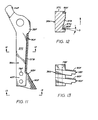
- FIGURE 11 is a front elevation of another embodiment of the invention showing a modified cutter arm and blade particularly adapted for cutting a plurality of concentric casing strings;
- FIGURE 12 is a section taken generally along line 12-12 of FIGURE 11;
- FIGURE 13 is a bottom plan of the modified cutter arm looking generally along line 13-13 of FIGURE 11;
- FIGURE 14 is an elevational view, partly in section, of a further embodiment of a cutting tool of this invention in which expanding cutter arms are pivotally mounted on a combined cutting and milling tool for first cutting the casing and then milling away a casing section progressively from the upper annular end of the cut casing;
- FIGURE 15 is a side elevation of a radially expandable cutter arm of the embodiment in FIGURE 14 shown removed from the cutting tool;
- FIGURE 16 is an end elevation of the radially expandable arm shown in FIGURE 15 showing the leading cutting surface of the blade inclined rearwardly from its upper end with respect to the direction of rotation;
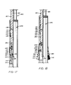
- FIGURE 17 is side elevation, partly in section, showing an additional embodiment of a cutting tool of this invention in which a combined cutting and milling tool is illustrated having a plurality of blades mounted on the lower end of a cutter arm and showing the cutter arms in a retracted position;
- FIGURE 18 is a view of the embodiment shown in FIGURE 17 but showing the cutter arms in a radially expanded position;
- FIGURE 19 is an enlarged side elevation view of a cutter arm removed from the cutting tool of FIGURE 18 and showing a plurality of cutting blades forming the present invention; and
- FIGURE 20 is an end elevation of the cutter arm shown in FIGURE 19.
- Referring now to the drawings for a better understanding of this invention, and more particularly to FIGURES 1 and 2, a well casing is shown at 10. A drill string is indicated generally at 12 and has its lower threaded
end 14 in threaded engagement with the upper end of anupper sub 16 defining acentral bore 18 to receive drilling fluid throughdrill string 12 from a surface location. A lower threadedend 20 ofupper sub 16 is received in threaded engagement within the upper end of a cutting tool generally indicated at 22. -
Cutting tool 22 has atubular cutter body 24 forming acentral bore 26 in which fluid pressure responsive means indicated generally at 28 is housed and is responsive to flowing drilling fluid fromdrill string 12 for hydraulic actuation as will be explained further.Cutting tool 22 has a lower reduceddiameter portion 30 with a lower internally threadedend 32. Three longitudinally extendingslots 34 are circumferentially spaced about the periphery oftubular cutter body 24 adjacent reduceddiameter portion 30 and receiveelongate cutter arms 36 of a generally rectangular cross- section having alongitudinal axis 37. Eachelongate arm 36 has anupper end portion 38 pivotally mounted by apin 40 tocutter body 24 and a lower downward extendingend portion 42. A tang or extension 44 extends upwardly fromupper end portion 38.Elongate arms 36 are free for pivoting between the retracted position shown in FIGURE 1 for lowering withincasing 10, and a radially expanded or extended position as shown in FIGURE 2 in whichlower end portions 42 ofarms 36 are swung or moved radially outwardly into cutting contact with the periphery ofcasing 10 to be cut. - Wells may have several concentric casing strings which are to be cut so that the length of
arms 36 and the amount of pivotal movement is preselected depending on the number and spacing of concentric casing strings to be cut. The embodiment of the invention shown in FIGURES 1-10 is particularly adapted for cutting a single casing string, but the embodiment shown in FIGURES 11-13 is adapted for cutting a plurality of concentric casing strings, if desired. In the cutting of a single casing string the cutting operation is normally accomplished in a single trip within the well by directing drilling fluid under pressure from the surface throughwell string 12 and by rotatingwell string 12 and cuttingtool 22 withcutter arms 36 pivoted into a radially expanded position into cutting contact with the periphery of casing 10 to be cut. The pivotal connections betweenarms 36 andcutter body 24 are designed so that the connections are sufficient to transmit the torque required to accomplish the cutting ofcasing 10. - For moving
lower end portions 42 ofcutter arms 36 radially outwardly into expanded cutting engagement withcasing 10, fluid pressure responsive means generally indicated at 28 includes apiston 46 mounted withincutter body 24 and continuously urged upwardly by spring 48. A pair of spaced flow restrictions or orifice rings are provided at 50 and are sized to provide a restriction to the downward flow of drilling fluid. Anindicator 52 adjacentupper orifice ring 50 has a plurality ofports 54 therein and when a predetermined fluid pressure differential is reached,piston 46 moves downwardly contacting tangs 44 to pivotcutter arms 36 outwardly radially into cutting engagement withcasing 10. Whencutter arms 36 are pivoted outwardly to radially extended position in contact withcasing 10, a decreased fluid pressure differential is indicated at the surface so that an operator is aware thatcutter arms 36 are in expanded cutting engagement with the inner periphery of casing 10 to be cut. - Forming an important part of this invention is the improved cutting blade assembly indicated at 57 mounted on the lower end of each
cutter arm 36.Cutter blade assembly 57 includes a pair of substantiallyidentical blades blades Cutter arm 36 has a pair of slots orgrooves lower end portion 42.Grooves finger 66 and a pair of end prongs orfingers finger 66.Fingers openings 72 therein.Blades shanks 74 received withingrooves openings 76 inshanks 74 are transversely aligned withopenings 72 infingers openings blades slots - Each
blade surface 82 and a generally parallel planar rear face orsurface 84.Front surface 82 forms a leading surface facing the direction of rotation and surface 84 forms a trailing surface with respect to the direction of rotation.Blade 58 diverges fromshank 74 to form a generally triangular shape as viewed in front elevation looking at planarfront face 82 and has radially spaced inner andouter apices apex 88 defines the cutting edge engaging the inner periphery of casing 10 in cutting relation. - With respect to the
longitudinal axis 37 ofelongate arm 36,blade 58 has anupper end 58A, alower end 58B, an innersloping side 58C, and an outersloping side 58D.Outer side 58D is positioned adjacent thecasing 10 to be cut.Lower end 58B has a portion thereof cutaway or notched to form notchedsurfaces 58E. - Referring particularly to FIGURES 6, 7, and 10,
finger 68 defines anouter surface 68A and aninner surface 68B,finger 70 definesouter surface 70A and inner surface 70B andcenter finger 66 defines opposedsurfaces 66A and 66B. With respect to the radially outermost side ofarm 36,finger 68 tapers upwardly andfinger 70 tapers downwardly to provide an increased thickness offinger 68 at its lower end and a decreased thickness offinger 70 at its lower end. With respect to the direction of rotation thelower end 58B ofblade 58 is tilted rearwardly with respect toupper end 58A at an angle A as shown in Figure 7. Angle A is of an optimum around five (5) degrees with an optimum range between around one degree (1 ° ) and fifteen (15) degrees . Under certain conditions of use, an angle A as high as twenty (20) degrees will function adequately. - Mounted on planar leading
surface 82adjacent apex 88 and on planar trailingsurface 84adjacent apex 86 are a plurality of hard carbide cutting elements or inserts comprising cylindrical carbide discs orbuttons 90 secured by suitable brazing or the like to the planar faces 82 and 84 ofbase 80. Inserts ordiscs 90 are preferably arranged in staggered rows extending fromapexes discs 90 therein. Adisc 90 which has been found to function in a satisfactory matter has a thickness of three sixteenths (3/16) inch (4.8 mm), a diameter of three eighths (3/8) inch (9.5 mm), and is sold under the name "Sandvik S6" by the Sandvik Company, located in Houston, Texas. - Each
cylindrical disc 90 has afront face 90A which forms a cutting face for leadingface 82 and an opposedrear face 90B which is flush with supportingbase 80 and brazed thereto. Acylindrical surface 90C connectsfaces rear faces annular cutting edge 90D formed at the juncture offront face 90A andcylindrical surface 90C digs or bites into the inner peripheral surface of casing 10 in cutting relation as shown in FIGURE 2. Front faces 90A ofdiscs 90 form the leading cutting surfaces onblade 58 and extend at angle A with respect to the axis of rotation as shown in Figure 7 thereby to provide a negative rake forfaces 90A andannular cutting edges 90D. As a result of the tilting of the leading cutting surface ofblades lower ends 58B rearwardly of upper ends 58A with respect to the direction of rotation, the cylindrical orannular surface 90C of eachdisc 90 has its longitudinal axis arranged at an angle B with respect to the transverse axis ofelongate arm 36. Angle B is equal to angle A sinceannular surface 90C extends along a longitudinal axis at right angles tofaces annular cutting edge 90D is presented to the inner periphery of casing 10 to be cut during the initial contact ofcarbide discs 90 withcasing 10. It is to be understood that any void areas formed betweendiscs 90 will be filled in during the bracing operation, such as with a nickel silver compound. Thus, a relatively smooth uninterrupted planar leading cutting surface is provided by the plurality ofdiscs 90. - When the cutting operation is commenced with an unused or
new carbide disc 90, asharp edge 90D initially contacts the inner periphery of the casing to be cut. Upon wear ofblades successive carbide discs 90 andcutting edges 90D are continually presented to the inner periphery ofcasing 10 sincediscs 90 withannular cutting edges 90D are staggered in three rows and the wear continues progressively from the radially outermost surfaces ofblades sharp cutting edge 90D ofdisc 90, not the entire width ofcylindrical surface 90C, is initially in contact withcasing 10 sincesurface 90C has a negative rake as defined by angle B. - Referring particularly to Figure 6,
outer side 58D ofblade 58 is positioned rearwardly ofinner side 58C with respect to the direction of rotation as indicated at angle C and this likewise tiltscylindrical surface 90C ofdisc 90 so that a greater portion ofannular cutting edge 90D ofdisc 90 is presented at an angle with respect tocasing 10. Angle C is preferably the same as angles A and B. -
Hard carbide disc 90 has a thickness indicated at D in Figure 6 of three-sixteenths (3/16) inch (4.8 mm), The thickness ofbase 80 ofblade 58 is shown at E in FIGURE 7 and is preferably around three-eighths (3/8) inch (9.5 mm) thick or around two (2) times the thickness ofdisc 90. Generally, a thickness ofbase 80 from around two (2) to four (4) times the thickness of insert ordisc 90 will function satisfactorily. In order to minimize any drag resulting fromblade 58 contactingcasing 10, the material from whichblade 58 is formed is of a mild steel having a Brinell hardness range of around one hundred forty-five (145) with an optimum Brinell hardness range of between around one hundred thirty (130) and one hundred sixty (160). Thecarbide discs 90 have a Rockwell A hardness of around eighty-five (85) to eighty-eight (88) which is around seven to nine times harder than the material from whichblade 58 is formed. For satisfactory results, it is believed thatdisc 90 should be at least around three (3) times harder thanblade 58. -
Casing 10 to be cut has a Brinell hardness of around two hundred (200) andcarbide discs 90 are around five (5) times harder than casing 10. As a result ofbase 80 being formed of a material several times as soft as thecarbide discs 90, the wear flat surface formed asbase 80 is worn away generates a minimum of friction which permits minimum torque for rotation ofdrill string 12 and cuttingtool 22. The spacing indicated at F in Figure 6 betweenblades forward blade 58 with respect to the axis of rotation. A spacing F of around one-half (1/2) inch (12.5 mm) has been found to function effectively. - It is noted that
discs 90 are provided adjacent bothinner side 58C ofblade 58 as well asouter side 58D.Discs 90 adjacentinner side 58C are inoperable during the cutting operation and are used only upon reversal ofblade 58 after wear ofouter side 58D.Blades cutting tool 22 from the well andinner sides 58C then becomeouter sides 58D.Blades - As a specific but non-limiting example, in which the embodiment of the present invention shown in FIGURES 1-10 was used to cut a casing forty-eight (48) inches (122 cm) in diameter and having a wall thickness of one and one-half (1-1/2) inches (3.8 cm),
blades - While
inserts 90 have been illustrated as cylindrical discs, it is to be understood that other shapes ofinserts 90 would function satisfactorily such as inserts of a square, rectangular, or triangular shape, for example. It is desirable, however, that cutting inserts have parallel planar rear and front faces with circumferential side surfaces between the parallel faces extending at right angles to the parallel faces. - Referring to FIGURES 11-13, another embodiment of a cutter arm forming the present invention is shown which is particularly adapted for cutting multiple concentric casing strings.
Cutter arm 36A has anupper end portion 38F with anextension 44F thereon and alower end portion 42F.Blades 58F and 60F are mounted on the lower end ofarm 36A by nut andbolt combinations 78F in a manner similar toarms Blades 58F and 60F are not illustrated as being reversible but, if desired,blades 58F, 60F could be made reversible as in the embodiment of FIGURES 1-10. For cutting through multiple casing strings,cutter arm 36A must project outwardly a maximum amount and might engage more than one casing string simultaneously. For this purpose, it is desirable to have a substantial length ofelongate cutter arm 36A provided with a cutting surface. - As shown particularly in Figure 12, the
outermost surface 37B ofelongate arm 36A has a leading row of carbide cutting elements or inserts illustrated asdiscs 90F along leadingsurface 37C and a generally parallel trailing row ofdiscs 90F mounted on aninset seat 37D ofsurface 37B.Carbide discs 90F have their outer planar faces extending at an angle G with respect to the direction of rotation which is the same as angle C of the embodiment of FIGURES 1-10 and provides a negative rake for contacting the adjacent casing string.Carbide discs 90F are identical tocarbide discs 90 shown in the embodiment of FIGURES 1-10. - Referring to FIGURES 14-16, another embodiment of the invention is illustrated for utilization particularly for cutting and milling casing within a well bore. The cutting and milling tool illustrated generally at 22B is particularly adapted for cutting and milling a casing section to form a "window" for removal of a predetermined length of the casing. The cutting and
milling tool 22B includesexpandable cutter arms 36B to move between expanded and retracted positions at selected depths and the tool is often referred to as a "section mill". A so-called section mill is particularly used in a sidetracking operation for sidetracking an existing bore hole. - As shown in FIGURE 14, cutting and milling tool shown at 22B having a tubular cutter
outer body 24B and acentral bore 26B which receives pressurized fluid from a surface location. Mounted withintubular body 24B is a mandrel 92 having respective upper andlower nozzles orifice ring 98 adjacent the upper end of mandrel 92 has a plurality of circumferentially spacedorifices 100 to receive drilling fluid therethrough. Apiston 102 is secured to the outer periphery of mandrel 92 for movement therewith. Aspring 104 is biased between ashoulder 106 forming a stop onbody 24B and ashoulder 108 onpiston 102 for continuously urging mandrel 92 to an upper position. -
Body 24B has a plurality of longitudinal extendingslots 34B spaced about its circumference. Mounted in eachslot 34B is acutter arm 36B pivotally mounted aboutpivot pin 40B secured tobody 24B.Cutter arm 36B has acam surface 110 formed on its inner rear surface and upon downward movement of mandrel 92, the lower end of mandrel 92 engagescam surface 110 tocam cutter arm 36B outwardly aboutpivot pin 40B into cutting engagement with the adjacent casing. The inner periphery of the casing is first engaged in a cutting operation for horizontally cutting the casing and thereafter the upper annular end of the casing is progressively milled or chipped away as is well known in the art for removal of a predetermined casing section. - Referring now to FIGURES 15 and 16 in which
cutter arm 36B is shown removed from millingtool 22B, the radially outermost surface ofcutter arm 36B is shown at 112 and the leading surface ofcutter arm 36B with respect to the axis of rotation is shown at 114. Mounted on radiallyoutermost surface 112 is a cutter blade generally indicated at 116 including a base 118 having a leadingplanar face 120 and arear trailing face 122 with respect to the axis of rotation ofcutter tool 22B.Base 118 has a lower end surface at 123. Rows of hard carbide cutting inserts ordiscs 124 are mounted on the planar leadingface 120 ofbase 118 and form a leading planar cutting face forblade 116. Eachdisc 124 is identical to thedisc 90 shown in the embodiment of FIGURES 1-10. -
Blade 116 has itslower end 123 inclined rearwardly with respect to the axis of rotation and the upper end ofblade 116. An angle A1 as shown in FIGURE 16 illustrates the inclination ofblade 116 and an angle A1 of between around three (3) degrees and five (5) degrees has been found to be optimum. An angle A1 of between around one (1) degree and ten (10) degrees is believed to function satisfactorily and under certain conditions it is believed that an angle AI as high as twenty (20) degrees would function. Disc or insert 124 has planar parallel rear and front faces with a circumferential surface between the faces extending at right angles thereto and arranged at an angle B1 with respect to the transverse axis ofelongate arm 36B which is of the same magnitude as angle A1. Thus, a negative rake is provided bylower end surface 123 and the leading planar cutting surface upon rotation of millingtool 22B. The thickness D1 ofbase 118 is around three-eighths (3/8) inch which is around twice the thickness of the associateddiscs 124 which is preferably around three-sixteenths (3/16) inch in thickness.Base 118 has a thickness preferably of around two (2) to four (4) times the thickness of the associateddiscs 124. The hardness ofbase 118 is similar to that for the embodiment shown in FIGURES 1-10. - During the initial cutting operation, the radially outermost edge of
blade 116 engages the inner periphery of the adjacent casing to cut the casing wall thereat. After the casing wall has been cut, a desired section or length of casing is removed by progressively milling or chipping away of the upper annular end of the casing formed by the horizontal cut until the desired casing section has been removed. - Referring now to FIGURES 17-20, an additional embodiment of a so-called section mill of this invention is illustrated in which pivotally mounted cutter arms are utilized with cutting blades and cutting inserts of the present invention.
- As shown in FIGURES 17 and 18, a mandrel or kelly is shown at 16C and has a
central bore 18C.Mandrel 16C is adapted to be connected to a suitable drill string for operation and control from a surface location. A tubular cutter body is shown generally at 24C and has acentral bore 26C receiving the lower end portion ofmandrel 16C.Cutter body 24C is mounted for longitudinal axial movement relative tomandrel 16C. -
Mandrel 16C includes a lowerannular nozzle 126 forming a choke. A lower annular extension orenlargement 128 onmandrel 16C forms an outerannular cam surface 130 thereon. An upper annular extension orenlargement 132 onmandrel 16C forms a piston and has alower shoulder 134 defining a stop forcutter body 24C. Apiston chamber 136 is provided above piston orannular extension 132 and afluid port 138 supplies fluid topiston chamber 136 for upward relative movement ofbody 24C relative tomandrel 16C upon circulation of fluid pressure applied throughbore 18C from a surface location.Body 24C has aninner shoulder 139 which provides an abutting surface forpiston 132 to act as a stop for the expanded position ofcutter arms 36C shown in FIGURE 18. Likewiseinner shoulder 141 acts as a stop to limit the downward relative movement ofbody 24C in the retracted position ofcutter arms 36C shown in FIGURE 17. -
Cutter body 24C has a plurality ofslots 34C formed therein and cutter arms generally designated 36C are mounted withinslots 34C for pivotal movement about pivot pins 40C.Cutter arm 36C has anupper shank 140 and alower blade head 142 thereon as shown particularly in FIGURES 19 and 20, acam surface 143 is provided on the rear inner surface ofarms 36C.Blade head 142 has a plurality ofblades 144 thereon arranged in generally parallel relation to each other and spaced from each other around three-fourths (3/4) inch, for example. Eachblade 144 has a base 145 having a trailingrear face 146 and a leadingfront face 148. The lower ends ofblades 144 are shown at 150 and form a lower end surface for riding along the upper annular end of a casing to be milled or chipped away progressively from the casing end. Rows of staggered inserts ordiscs 154 are mounted on the front planar leadingface 148 of eachblade 144 and define a leading planar cutting surface at 156 and a lower cutting edge or surface along thelower end surface 150 ofblades 144.Blades 144 and inserts 154 are identical in dimension to corresponding discs and blades set forth for the embodiment of FIGURES 1-10. Likewise, angles A2 and B2 shown on FIGURE 20 are identical to angles A and B for the embodiment of FIGURES 1-10. The leadingplanar cutting surface 156 formed bydiscs 154 is arranged at an angle A2 with respect to the longitudinal axis of cuttingtool 22C. Each insert ordisc 154 has an outer cylindrical surface which presents an annular cutting edge extending at angle B2 with respect to the transverse axis of cuttingarm 36C as set forth in the embodiment of FIGURES 1-10 fordisc 90. Angle B2 is equal to angle A2 and provides a negative rake resulting from a tilting of the planar leadingsurface 148 of associatedblade 144 - In operation for the embodiment shown in FIGURES 17-20, during the run-in of
mandrel 16C,cutter arms 36C are in the position shown in FIGURE 17 as fluid pressure inbore 18C is dampened. When desired to expandarms 36C, circulation fluid pressure is applied to bore 18C and fluid pressure throughport 138 tofluid chamber 136 movesbody 24C to the position of FIGURE 18 relative tomandrel 16C in which shoulder 139contacts piston 132. Upon such upward movement ofbody 24C,cam surface 130 onmandrel 16C engagesinner cam surface 143 onarm 36C andcam arm 36C radially outwardly to the expanded cutting position shown in FIGURE 18. In this position,cutter arms 36C are locked in place and stay in locked position as long as fluid pressure or drilling weight is applied. To returncutter arms 36C to retracted position as shown in FIGURE 17, fluid pressure may be reduced andmandrel 16C raised. In this position,cam surface 130 onmandrel 16C will be moved upwardly relative to cooperatingcam surface 143 onarm 36C andarm 36C will return to the position shown in FIGURE 17. Thus, circulation pressure of the fluid is employed only to movecutter arms 36C to an open expanded position and the drilling weight maintainscutter arms 36C in an open position. There is no requirement for a continuous or constant fluid pressure from a fluid pump. Further, there are no springs employed for urging the cutter arms outwardly or for the return of the cutter arms to a retracted position as the arms can be retracted merely by a lifting ofmandrel 16C. - It is to be understood that the cutting inserts illustrated for all of the embodiments of this invention may be of a shape other than a cylindrical shape as shown specifically in the drawings and yet function in a satisfactory manner. For example, inserts of a square, rectangular, or triangular shape would function adequately. It is desirable, however, that such cutting inserts have generally parallel front and rear planar faces with the circumferential side surfaces between the parallel faces extending at right angles to the faces.
- While several embodiments of the present invention have been illustrated in detail, it is apparent that modifications and adaptations of the embodiments shown will occur to those skilled in the art. However, it is to be expressly understood that such modifications and adaptations are within the spirit and scope of the present invention as set forth in the following claims.
characterised in that said cutting means includes a base having a leading surface with respect to the rotational axis of said cutting tool during the cutting operation; and
Claims (15)
characterised in that said cutting means includes a base (80) having a leading surface (82) with respect to the rotational axis of said cutting tool (22) during the cutting operation; and
plurality of hard carbide inserts (90) on said leading face of said blade (58, 60) form a planar cutting surface outwardly of said arm.
means (78) mount said blade (58, 60) on said arm (36) for removal whereby said blade (58, 60) upon its leading face (82) being worn may be removed and reversed thereby to convert the original trailing face (84) to a leading face for forming the cutting surface.
Applications Claiming Priority (2)
| Application Number | Priority Date | Filing Date | Title |
|---|---|---|---|
| US927512 | 1986-11-06 | ||
| US07/927,512 US4887668A (en) | 1986-01-06 | 1986-11-06 | Cutting tool for cutting well casing |
Publications (4)
| Publication Number | Publication Date |
|---|---|
| EP0266864A2 EP0266864A2 (en) | 1988-05-11 |
| EP0266864A3 EP0266864A3 (en) | 1989-05-24 |
| EP0266864B1 true EP0266864B1 (en) | 1992-06-17 |
| EP0266864B2 EP0266864B2 (en) | 2000-07-26 |
Family
ID=25454837
Family Applications (1)
| Application Number | Title | Priority Date | Filing Date |
|---|---|---|---|
| EP87307098A Expired - Lifetime EP0266864B2 (en) | 1986-11-06 | 1987-08-11 | Cutting tool for cutting well casing |
Country Status (6)
| Country | Link |
|---|---|
| US (1) | US4887668A (en) |
| EP (1) | EP0266864B2 (en) |
| AU (1) | AU608526B2 (en) |
| CA (1) | CA1284100C (en) |
| DE (1) | DE3779867T3 (en) |
| NO (1) | NO177397B (en) |
Cited By (1)
| Publication number | Priority date | Publication date | Assignee | Title |
|---|---|---|---|---|
| US5456312A (en) | 1986-01-06 | 1995-10-10 | Baker Hughes Incorporated | Downhole milling tool |
Families Citing this family (81)
| Publication number | Priority date | Publication date | Assignee | Title |
|---|---|---|---|---|
| US4796709A (en) * | 1986-01-06 | 1989-01-10 | Tri-State Oil Tool Industries, Inc. | Milling tool for cutting well casing |
| US4978260A (en) * | 1986-01-06 | 1990-12-18 | Tri-State Oil Tools, Inc. | Cutting tool for removing materials from well bore |
| NO893075L (en) * | 1988-07-30 | 1990-01-31 | Tri State Oil Tool | CUTTING DEVICE FOR LINING BEETS. |
| GB8908014D0 (en) * | 1989-04-10 | 1989-05-24 | Smith Int North Sea | A milling tool stabiliser |
| GB9003047D0 (en) * | 1990-02-10 | 1990-04-11 | Tri State Oil Tool Uk | Insert type window mill |
| US5035293A (en) * | 1990-09-12 | 1991-07-30 | Rives Allen K | Blade or member to drill or enlarge a bore in the earth and method of forming |
| GB2299115A (en) * | 1992-10-19 | 1996-09-25 | Baker Hughes Inc | Retrievable whipstock system |
| US5787978A (en) * | 1995-03-31 | 1998-08-04 | Weatherford/Lamb, Inc. | Multi-face whipstock with sacrificial face element |
| US5720349A (en) * | 1995-10-12 | 1998-02-24 | Weatherford U.S., Inc. | Starting mill and operations |
| US6202752B1 (en) | 1993-09-10 | 2001-03-20 | Weatherford/Lamb, Inc. | Wellbore milling methods |
| US6024168A (en) * | 1996-01-24 | 2000-02-15 | Weatherford/Lamb, Inc. | Wellborne mills & methods |
| US5887655A (en) * | 1993-09-10 | 1999-03-30 | Weatherford/Lamb, Inc | Wellbore milling and drilling |
| US5836387A (en) * | 1993-09-10 | 1998-11-17 | Weatherford/Lamb, Inc. | System for securing an item in a tubular channel in a wellbore |
| US5727629A (en) * | 1996-01-24 | 1998-03-17 | Weatherford/Lamb, Inc. | Wellbore milling guide and method |
| US5887668A (en) * | 1993-09-10 | 1999-03-30 | Weatherford/Lamb, Inc. | Wellbore milling-- drilling |
| US6070665A (en) * | 1996-05-02 | 2000-06-06 | Weatherford/Lamb, Inc. | Wellbore milling |
| US5806595A (en) * | 1993-09-10 | 1998-09-15 | Weatherford/Lamb, Inc. | Wellbore milling system and method |
| US5826651A (en) * | 1993-09-10 | 1998-10-27 | Weatherford/Lamb, Inc. | Wellbore single trip milling |
| US5803176A (en) * | 1996-01-24 | 1998-09-08 | Weatherford/Lamb, Inc. | Sidetracking operations |
| US6056056A (en) * | 1995-03-31 | 2000-05-02 | Durst; Douglas G. | Whipstock mill |
| US5636692A (en) * | 1995-12-11 | 1997-06-10 | Weatherford Enterra U.S., Inc. | Casing window formation |
| US5709265A (en) * | 1995-12-11 | 1998-01-20 | Weatherford/Lamb, Inc. | Wellbore window formation |
| US5908071A (en) * | 1995-09-22 | 1999-06-01 | Weatherford/Lamb, Inc. | Wellbore mills and inserts |
| US5862870A (en) * | 1995-09-22 | 1999-01-26 | Weatherford/Lamb, Inc. | Wellbore section milling |
| US5642787A (en) * | 1995-09-22 | 1997-07-01 | Weatherford U.S., Inc. | Section milling |
| US6170576B1 (en) | 1995-09-22 | 2001-01-09 | Weatherford/Lamb, Inc. | Mills for wellbore operations |
| US5791417A (en) * | 1995-09-22 | 1998-08-11 | Weatherford/Lamb, Inc. | Tubular window formation |
| US5984005A (en) * | 1995-09-22 | 1999-11-16 | Weatherford/Lamb, Inc. | Wellbore milling inserts and mills |
| US5626189A (en) * | 1995-09-22 | 1997-05-06 | Weatherford U.S., Inc. | Wellbore milling tools and inserts |
| US6547006B1 (en) | 1996-05-02 | 2003-04-15 | Weatherford/Lamb, Inc. | Wellbore liner system |
| US6155349A (en) * | 1996-05-02 | 2000-12-05 | Weatherford/Lamb, Inc. | Flexible wellbore mill |
| US5735359A (en) * | 1996-06-10 | 1998-04-07 | Weatherford/Lamb, Inc. | Wellbore cutting tool |
| AU719919B2 (en) * | 1996-07-15 | 2000-05-18 | Halliburton Energy Services, Inc. | Apparatus for completing a subterranean well and associated methods of using same |
| CA2209958A1 (en) * | 1996-07-15 | 1998-01-15 | James M. Barker | Apparatus for completing a subterranean well and associated methods of using same |
| CA2210563C (en) * | 1996-07-15 | 2004-03-02 | Halliburton Energy Services, Inc. | Apparatus for completing a subterranean well and associated methods of using same |
| US5730221A (en) * | 1996-07-15 | 1998-03-24 | Halliburton Energy Services, Inc | Methods of completing a subterranean well |
| US5813465A (en) * | 1996-07-15 | 1998-09-29 | Halliburton Energy Services, Inc. | Apparatus for completing a subterranean well and associated methods of using same |
| AU714721B2 (en) * | 1996-07-15 | 2000-01-06 | Halliburton Energy Services, Inc. | Apparatus for completing a subterranean well and associated methods of using same |
| CA2210561C (en) * | 1996-07-15 | 2004-04-06 | Halliburton Energy Services, Inc. | Apparatus for completing a subterranean well and associated methods of using same |
| US5833003A (en) * | 1996-07-15 | 1998-11-10 | Halliburton Energy Services, Inc. | Apparatus for completing a subterranean well and associated methods of using same |
| US5862862A (en) * | 1996-07-15 | 1999-01-26 | Halliburton Energy Services, Inc. | Apparatus for completing a subterranean well and associated methods of using same |
| US5732770A (en) * | 1996-08-02 | 1998-03-31 | Weatherford/Lamb, Inc. | Wellbore cutter |
| US6076601A (en) * | 1998-06-11 | 2000-06-20 | Halliburton Energy Services, Inc. | Collapsible cutter apparatus and method for cutting tubular members |
| US6962216B2 (en) | 2002-05-31 | 2005-11-08 | Cdx Gas, Llc | Wedge activated underreamer |
| US6374918B2 (en) | 1999-05-14 | 2002-04-23 | Weatherford/Lamb, Inc. | In-tubing wellbore sidetracking operations |
| US6412556B1 (en) | 2000-08-03 | 2002-07-02 | Cdx Gas, Inc. | Cavity positioning tool and method |
| GB2373266B (en) | 2001-03-13 | 2004-08-18 | Sondex Ltd | Apparatus for anchoring a tool within a tubular |
| US7451836B2 (en) | 2001-08-08 | 2008-11-18 | Smith International, Inc. | Advanced expandable reaming tool |
| US6722452B1 (en) * | 2002-02-19 | 2004-04-20 | Cdx Gas, Llc | Pantograph underreamer |
| US6991040B2 (en) | 2002-07-12 | 2006-01-31 | Weatherford/Lamb, Inc. | Method and apparatus for locking out a subsurface safety valve |
| US6976547B2 (en) | 2002-07-16 | 2005-12-20 | Cdx Gas, Llc | Actuator underreamer |
| US6851479B1 (en) | 2002-07-17 | 2005-02-08 | Cdx Gas, Llc | Cavity positioning tool and method |
| US7007758B2 (en) * | 2002-07-17 | 2006-03-07 | Cdx Gas, Llc | Cavity positioning tool and method |
| US7188674B2 (en) | 2002-09-05 | 2007-03-13 | Weatherford/Lamb, Inc. | Downhole milling machine and method of use |
| US7182157B2 (en) | 2004-12-21 | 2007-02-27 | Cdx Gas, Llc | Enlarging well bores having tubing therein |
| US7575056B2 (en) | 2007-03-26 | 2009-08-18 | Baker Hughes Incorporated | Tubular cutting device |
| US7644763B2 (en) * | 2007-03-26 | 2010-01-12 | Baker Hughes Incorporated | Downhole cutting tool and method |
| US7823632B2 (en) * | 2008-06-14 | 2010-11-02 | Completion Technologies, Inc. | Method and apparatus for programmable robotic rotary mill cutting of multiple nested tubulars |
| US9759030B2 (en) | 2008-06-14 | 2017-09-12 | Tetra Applied Technologies, Llc | Method and apparatus for controlled or programmable cutting of multiple nested tubulars |
| US8210251B2 (en) * | 2009-04-14 | 2012-07-03 | Baker Hughes Incorporated | Slickline conveyed tubular cutter system |
| US8469097B2 (en) * | 2009-05-14 | 2013-06-25 | Baker Hughes Incorporated | Subterranean tubular cutter with depth of cut feature |
| US8555955B2 (en) | 2010-12-21 | 2013-10-15 | Baker Hughes Incorporated | One trip multiple string section milling of subterranean tubulars |
| US9404331B2 (en) | 2012-07-31 | 2016-08-02 | Smith International, Inc. | Extended duration section mill and methods of use |
| US9366101B2 (en) | 2012-10-04 | 2016-06-14 | Baker Hughes Incorporated | Cutting and pulling tool with double acting hydraulic piston |
| US9725977B2 (en) | 2012-10-04 | 2017-08-08 | Baker Hughes Incorporated | Retractable cutting and pulling tool with uphole milling capability |
| US9080402B2 (en) | 2013-03-06 | 2015-07-14 | Enventure Global Technology, Inc. | Method and apparatus for removing unexpanded shoe |
| GB2520998B (en) | 2013-12-06 | 2016-06-29 | Schlumberger Holdings | Expandable Reamer |
| US10030459B2 (en) * | 2014-07-08 | 2018-07-24 | Smith International, Inc. | Thru-casing milling |
| GB2528457B (en) | 2014-07-21 | 2018-10-10 | Schlumberger Holdings | Reamer |
| GB2528459B (en) | 2014-07-21 | 2018-10-31 | Schlumberger Holdings | Reamer |
| GB2535787B (en) | 2015-02-27 | 2017-08-16 | Schlumberger Holdings | Milling tool and method |
| GB2528458A (en) | 2014-07-21 | 2016-01-27 | Schlumberger Holdings | Reamer |
| US10519722B2 (en) | 2014-07-21 | 2019-12-31 | Schlumberger Technology Corporation | Reamer |
| GB2528456A (en) | 2014-07-21 | 2016-01-27 | Schlumberger Holdings | Reamer |
| GB2528454A (en) | 2014-07-21 | 2016-01-27 | Schlumberger Holdings | Reamer |
| US11047194B2 (en) * | 2014-09-22 | 2021-06-29 | Statoil Petroleum As | Method and system for removing iron-containing casing from a well bore |
| GB2531503B (en) * | 2014-09-22 | 2017-05-17 | Statoil Petroleum As | Method |
| NO341205B1 (en) | 2015-05-19 | 2017-09-11 | Sintef Tto As | Milling tool with self driven active side cutters |
| GB2563564B (en) * | 2017-04-13 | 2020-09-09 | Weatherford Uk Ltd | Downhole apparatus |
| CN110748299B (en) * | 2019-11-08 | 2021-01-05 | 西南石油大学 | Compound broken super reducing drill bit of natural gas hydrate exploitation |
| EP3879068A1 (en) * | 2020-03-11 | 2021-09-15 | Welltec Oilfield Solutions AG | Downhole line separation tool |
Family Cites Families (26)
| Publication number | Priority date | Publication date | Assignee | Title |
|---|---|---|---|---|
| US2337322A (en) * | 1940-06-29 | 1943-12-21 | Gascoigne Joseph Colin | Cutting tool having tip or insert of tungsten carbide or like hard materials |
| US2328494A (en) * | 1942-05-07 | 1943-08-31 | O K Tool Co Inc | Milling cutter |
| US2709490A (en) * | 1951-09-28 | 1955-05-31 | A 1 Bit & Tool Company Inc | Tool for severing and milling away a section of casing in the bore of a well |
| US2922627A (en) * | 1956-06-07 | 1960-01-26 | Rotary Oil Tool Company | Rotary drill bits and cutters |
| US2859943A (en) * | 1957-01-07 | 1958-11-11 | Chadderdon Jack | Expansible mill for well casings |
| US2846193A (en) * | 1957-01-07 | 1958-08-05 | Chadderdon Jack | Milling cutter for use in oil wells |
| US2999541A (en) * | 1957-10-11 | 1961-09-12 | Kinzbach Tool Company Inc | Milling tool |
| US3110084A (en) * | 1958-08-15 | 1963-11-12 | Robert B Kinzbach | Piloted milling tool |
| US3059708A (en) * | 1959-08-07 | 1962-10-23 | Jersey Prod Res Co | Abrasion resistant stepped blade rotary drill bit |
| US3147536A (en) * | 1961-10-27 | 1964-09-08 | Kammerer Jr Archer W | Apparatus for milling tubular strings in well bores |
| US3114416A (en) * | 1961-11-13 | 1963-12-17 | Archer W Kammerer | Liner hanger and liner milling tool |
| US3195636A (en) * | 1962-09-07 | 1965-07-20 | Servco Co | Apparatus for cutting and milling in well bores |
| US3145790A (en) * | 1963-06-10 | 1964-08-25 | Jersey Prod Res Co | Drag bit |
| US3331439A (en) * | 1964-08-14 | 1967-07-18 | Sanford Lawrence | Multiple cutting tool |
| US3378072A (en) * | 1966-09-09 | 1968-04-16 | Samuel H. Smith | Method and apparatus for severing well casing in a submarine environment |
| US3514828A (en) * | 1968-04-08 | 1970-06-02 | Marwin Cutting Tools Ltd | End-milling cutters |
| SU869975A1 (en) * | 1979-12-17 | 1981-10-07 | за витель Б. А. Каганович | Apparatus for working ends of thin-walled tubes |
| US4459883A (en) * | 1982-02-04 | 1984-07-17 | Tri Tool, Inc. | Portable machine tool for preparing pipe joints for welding |
| US4431065A (en) † | 1982-02-26 | 1984-02-14 | Smith International, Inc. | Underreamer |
| US4452325A (en) * | 1982-09-27 | 1984-06-05 | Conoco Inc. | Composite structure for cutting tools |
| JPS5978495A (en) † | 1982-10-27 | 1984-05-07 | オリンパス光学工業株式会社 | Lamp firing circuit |
| JPS59176713U (en) † | 1983-05-13 | 1984-11-26 | 富士精工株式会社 | Drill end mill |
| US4499795A (en) * | 1983-09-23 | 1985-02-19 | Strata Bit Corporation | Method of drill bit manufacture |
| US4550781A (en) * | 1984-06-06 | 1985-11-05 | A-Z International Tool Company | Method of and apparatus for cutting and recovering of submarine surface casing |
| US4710074A (en) * | 1985-12-04 | 1987-12-01 | Smith International, Inc. | Casing mill |
| US4796709A (en) † | 1986-01-06 | 1989-01-10 | Tri-State Oil Tool Industries, Inc. | Milling tool for cutting well casing |
-
1986
- 1986-11-06 US US07/927,512 patent/US4887668A/en not_active Expired - Lifetime
-
1987
- 1987-08-04 AU AU76555/87A patent/AU608526B2/en not_active Expired
- 1987-08-11 EP EP87307098A patent/EP0266864B2/en not_active Expired - Lifetime
- 1987-08-11 DE DE3779867T patent/DE3779867T3/en not_active Expired - Lifetime
- 1987-10-09 CA CA000549048A patent/CA1284100C/en not_active Expired - Lifetime
- 1987-11-05 NO NO874622A patent/NO177397B/en unknown
Cited By (3)
| Publication number | Priority date | Publication date | Assignee | Title |
|---|---|---|---|---|
| US5456312A (en) | 1986-01-06 | 1995-10-10 | Baker Hughes Incorporated | Downhole milling tool |
| US5810079A (en) | 1986-01-06 | 1998-09-22 | Baker Hughes Incorporated | Downhole milling tool |
| US5899268A (en) | 1986-01-06 | 1999-05-04 | Baker Hughes Incorporated | Downhole milling tool |
Also Published As
| Publication number | Publication date |
|---|---|
| EP0266864A3 (en) | 1989-05-24 |
| AU608526B2 (en) | 1991-04-11 |
| DE3779867D1 (en) | 1992-07-23 |
| NO177397B (en) | 1995-05-29 |
| US4887668A (en) | 1989-12-19 |
| NO874622L (en) | 1988-05-09 |
| EP0266864A2 (en) | 1988-05-11 |
| DE3779867T3 (en) | 2001-03-08 |
| NO874622D0 (en) | 1987-11-05 |
| CA1284100C (en) | 1991-05-14 |
| DE3779867T2 (en) | 1993-01-28 |
| EP0266864B2 (en) | 2000-07-26 |
| AU7655587A (en) | 1988-05-12 |
Similar Documents
| Publication | Publication Date | Title |
|---|---|---|
| EP0266864B1 (en) | Cutting tool for cutting well casing | |
| US4938291A (en) | Cutting tool for cutting well casing | |
| US5242017A (en) | Cutter blades for rotary tubing tools | |
| EP0376433B1 (en) | Improved cutting tool for removing man-made members from well bore | |
| EP1096103B1 (en) | Drill-out bi-center bit | |
| US5582261A (en) | Drill bit having enhanced cutting structure and stabilizing features | |
| CA2155392C (en) | Drill bit having enhanced cutting structure and stabilizing features | |
| US8833492B2 (en) | Cutters for fixed cutter bits | |
| EP0430590B1 (en) | Improvements in or relating to rotary drill bits | |
| US9574405B2 (en) | Hybrid disc bit with optimized PDC cutter placement | |
| EP0707130B1 (en) | Rotary drill bits | |
| US5150755A (en) | Milling tool and method for milling multiple casing strings | |
| US5558170A (en) | Method and apparatus for improving drill bit stability | |
| US7025156B1 (en) | Rotary drill bit for casting milling and formation drilling | |
| EP0972908B1 (en) | A method of determining characteristics of a rotary drag-type drill bit | |
| US4607711A (en) | Rotary drill bit with cutting elements having a thin abrasive front layer | |
| EP1288432B1 (en) | Drill bit with PDC cutters with different backrake angles | |
| US6021858A (en) | Drill bit having trapezium-shaped blades | |
| US5505273A (en) | Compound diamond cutter | |
| GB2421042A (en) | Drill bit with secondary cutters for hard formations | |
| US20010020551A1 (en) | Rotary drag-type drill bits and methods of designing such bits | |
| WO2015013354A1 (en) | Cutter support element | |
| GB2317195A (en) | A fixed cutter drill bit | |
| US20020066600A1 (en) | Rotary tools or bits | |
| US20100175929A1 (en) | Cutter profile helping in stability and steerability |
Legal Events
| Date | Code | Title | Description |
|---|---|---|---|
| PUAI | Public reference made under article 153(3) epc to a published international application that has entered the european phase |
Free format text: ORIGINAL CODE: 0009012 |
|
| AK | Designated contracting states |
Kind code of ref document: A2 Designated state(s): BE DE FR GB IT NL SE |
|
| PUAL | Search report despatched |
Free format text: ORIGINAL CODE: 0009013 |
|
| AK | Designated contracting states |
Kind code of ref document: A3 Designated state(s): BE DE FR GB IT NL SE |
|
| 17P | Request for examination filed |
Effective date: 19891026 |
|
| 17Q | First examination report despatched |
Effective date: 19900215 |
|
| GRAA | (expected) grant |
Free format text: ORIGINAL CODE: 0009210 |
|
| AK | Designated contracting states |
Kind code of ref document: B1 Designated state(s): BE DE FR GB IT NL SE |
|
| ITF | It: translation for a ep patent filed |
Owner name: JACOBACCI & PERANI S.P.A. |
|
| REF | Corresponds to: |
Ref document number: 3779867 Country of ref document: DE Date of ref document: 19920723 |
|
| PGFP | Annual fee paid to national office [announced via postgrant information from national office to epo] |
Ref country code: BE Payment date: 19920804 Year of fee payment: 6 |
|
| PGFP | Annual fee paid to national office [announced via postgrant information from national office to epo] |
Ref country code: FR Payment date: 19920818 Year of fee payment: 6 |
|
| ET | Fr: translation filed | ||
| PLBI | Opposition filed |
Free format text: ORIGINAL CODE: 0009260 |
|
| 26 | Opposition filed |
Opponent name: THE RED BARON (OIL TOOLS RENTAL) LIMITED Effective date: 19930312 |
|
| NLR1 | Nl: opposition has been filed with the epo |
Opponent name: THE RED BARON (OIL TOOLS RENTAL) LIMITED. |
|
| PG25 | Lapsed in a contracting state [announced via postgrant information from national office to epo] |
Ref country code: BE Effective date: 19930831 |
|
| BERE | Be: lapsed |
Owner name: TRI-STATE OIL TOOL INDUSTRIES INC. Effective date: 19930831 |
|
| PG25 | Lapsed in a contracting state [announced via postgrant information from national office to epo] |
Ref country code: FR Effective date: 19940429 |
|
| REG | Reference to a national code |
Ref country code: FR Ref legal event code: ST |
|
| EAL | Se: european patent in force in sweden |
Ref document number: 87307098.1 |
|
| APAC | Appeal dossier modified |
Free format text: ORIGINAL CODE: EPIDOS NOAPO |
|
| PLAW | Interlocutory decision in opposition |
Free format text: ORIGINAL CODE: EPIDOS IDOP |
|
| PLAW | Interlocutory decision in opposition |
Free format text: ORIGINAL CODE: EPIDOS IDOP |
|
| PUAH | Patent maintained in amended form |
Free format text: ORIGINAL CODE: 0009272 |
|
| STAA | Information on the status of an ep patent application or granted ep patent |
Free format text: STATUS: PATENT MAINTAINED AS AMENDED |
|
| 27A | Patent maintained in amended form |
Effective date: 20000726 |
|
| AK | Designated contracting states |
Kind code of ref document: B2 Designated state(s): BE DE FR GB IT NL SE |
|
| NLR2 | Nl: decision of opposition | ||
| ITF | It: translation for a ep patent filed |
Owner name: JACOBACCI & PERANI S.P.A. |
|
| ET3 | Fr: translation filed ** decision concerning opposition | ||
| NLR3 | Nl: receipt of modified translations in the netherlands language after an opposition procedure | ||
| PGFP | Annual fee paid to national office [announced via postgrant information from national office to epo] |
Ref country code: GB Payment date: 20010720 Year of fee payment: 15 |
|
| REG | Reference to a national code |
Ref country code: GB Ref legal event code: IF02 |
|
| PG25 | Lapsed in a contracting state [announced via postgrant information from national office to epo] |
Ref country code: GB Free format text: LAPSE BECAUSE OF NON-PAYMENT OF DUE FEES Effective date: 20020811 |
|
| GBPC | Gb: european patent ceased through non-payment of renewal fee |
Effective date: 20020811 |
|
| PG25 | Lapsed in a contracting state [announced via postgrant information from national office to epo] |
Ref country code: IT Free format text: LAPSE BECAUSE OF NON-PAYMENT OF DUE FEES Effective date: 20050811 |
|
| APAH | Appeal reference modified |
Free format text: ORIGINAL CODE: EPIDOSCREFNO |
|
| PGFP | Annual fee paid to national office [announced via postgrant information from national office to epo] |
Ref country code: NL Payment date: 20060824 Year of fee payment: 20 |
|
| PGFP | Annual fee paid to national office [announced via postgrant information from national office to epo] |
Ref country code: DE Payment date: 20061002 Year of fee payment: 20 |
|
| NLV7 | Nl: ceased due to reaching the maximum lifetime of a patent |
Effective date: 20070811 |
|
| EUG | Se: european patent has lapsed | ||
| PG25 | Lapsed in a contracting state [announced via postgrant information from national office to epo] |
Ref country code: NL Free format text: LAPSE BECAUSE OF EXPIRATION OF PROTECTION Effective date: 20070811 |
|
| PGFP | Annual fee paid to national office [announced via postgrant information from national office to epo] |
Ref country code: SE Payment date: 20060829 Year of fee payment: 20 |