EP0266829B1 - Joystick - Google Patents
Joystick Download PDFInfo
- Publication number
- EP0266829B1 EP0266829B1 EP87202051A EP87202051A EP0266829B1 EP 0266829 B1 EP0266829 B1 EP 0266829B1 EP 87202051 A EP87202051 A EP 87202051A EP 87202051 A EP87202051 A EP 87202051A EP 0266829 B1 EP0266829 B1 EP 0266829B1
- Authority
- EP
- European Patent Office
- Prior art keywords
- substrate
- control
- measuring unit
- coil
- handle
- Prior art date
- Legal status (The legal status is an assumption and is not a legal conclusion. Google has not performed a legal analysis and makes no representation as to the accuracy of the status listed.)
- Expired - Lifetime
Links
Images


Classifications
-
- G—PHYSICS
- G01—MEASURING; TESTING
- G01D—MEASURING NOT SPECIALLY ADAPTED FOR A SPECIFIC VARIABLE; ARRANGEMENTS FOR MEASURING TWO OR MORE VARIABLES NOT COVERED IN A SINGLE OTHER SUBCLASS; TARIFF METERING APPARATUS; MEASURING OR TESTING NOT OTHERWISE PROVIDED FOR
- G01D5/00—Mechanical means for transferring the output of a sensing member; Means for converting the output of a sensing member to another variable where the form or nature of the sensing member does not constrain the means for converting; Transducers not specially adapted for a specific variable
- G01D5/12—Mechanical means for transferring the output of a sensing member; Means for converting the output of a sensing member to another variable where the form or nature of the sensing member does not constrain the means for converting; Transducers not specially adapted for a specific variable using electric or magnetic means
- G01D5/14—Mechanical means for transferring the output of a sensing member; Means for converting the output of a sensing member to another variable where the form or nature of the sensing member does not constrain the means for converting; Transducers not specially adapted for a specific variable using electric or magnetic means influencing the magnitude of a current or voltage
- G01D5/20—Mechanical means for transferring the output of a sensing member; Means for converting the output of a sensing member to another variable where the form or nature of the sensing member does not constrain the means for converting; Transducers not specially adapted for a specific variable using electric or magnetic means influencing the magnitude of a current or voltage by varying inductance, e.g. by a movable armature
- G01D5/204—Mechanical means for transferring the output of a sensing member; Means for converting the output of a sensing member to another variable where the form or nature of the sensing member does not constrain the means for converting; Transducers not specially adapted for a specific variable using electric or magnetic means influencing the magnitude of a current or voltage by varying inductance, e.g. by a movable armature by influencing the mutual induction between two or more coils
- G01D5/2073—Mechanical means for transferring the output of a sensing member; Means for converting the output of a sensing member to another variable where the form or nature of the sensing member does not constrain the means for converting; Transducers not specially adapted for a specific variable using electric or magnetic means influencing the magnitude of a current or voltage by varying inductance, e.g. by a movable armature by influencing the mutual induction between two or more coils by movement of a single coil with respect to two or more coils
-
- G—PHYSICS
- G05—CONTROLLING; REGULATING
- G05G—CONTROL DEVICES OR SYSTEMS INSOFAR AS CHARACTERISED BY MECHANICAL FEATURES ONLY
- G05G9/00—Manually-actuated control mechanisms provided with one single controlling member co-operating with two or more controlled members, e.g. selectively, simultaneously
- G05G9/02—Manually-actuated control mechanisms provided with one single controlling member co-operating with two or more controlled members, e.g. selectively, simultaneously the controlling member being movable in different independent ways, movement in each individual way actuating one controlled member only
- G05G9/04—Manually-actuated control mechanisms provided with one single controlling member co-operating with two or more controlled members, e.g. selectively, simultaneously the controlling member being movable in different independent ways, movement in each individual way actuating one controlled member only in which movement in two or more ways can occur simultaneously
- G05G9/047—Manually-actuated control mechanisms provided with one single controlling member co-operating with two or more controlled members, e.g. selectively, simultaneously the controlling member being movable in different independent ways, movement in each individual way actuating one controlled member only in which movement in two or more ways can occur simultaneously the controlling member being movable by hand about orthogonal axes, e.g. joysticks
- G05G2009/04703—Mounting of controlling member
- G05G2009/04707—Mounting of controlling member with ball joint
-
- G—PHYSICS
- G05—CONTROLLING; REGULATING
- G05G—CONTROL DEVICES OR SYSTEMS INSOFAR AS CHARACTERISED BY MECHANICAL FEATURES ONLY
- G05G9/00—Manually-actuated control mechanisms provided with one single controlling member co-operating with two or more controlled members, e.g. selectively, simultaneously
- G05G9/02—Manually-actuated control mechanisms provided with one single controlling member co-operating with two or more controlled members, e.g. selectively, simultaneously the controlling member being movable in different independent ways, movement in each individual way actuating one controlled member only
- G05G9/04—Manually-actuated control mechanisms provided with one single controlling member co-operating with two or more controlled members, e.g. selectively, simultaneously the controlling member being movable in different independent ways, movement in each individual way actuating one controlled member only in which movement in two or more ways can occur simultaneously
- G05G9/047—Manually-actuated control mechanisms provided with one single controlling member co-operating with two or more controlled members, e.g. selectively, simultaneously the controlling member being movable in different independent ways, movement in each individual way actuating one controlled member only in which movement in two or more ways can occur simultaneously the controlling member being movable by hand about orthogonal axes, e.g. joysticks
- G05G2009/0474—Manually-actuated control mechanisms provided with one single controlling member co-operating with two or more controlled members, e.g. selectively, simultaneously the controlling member being movable in different independent ways, movement in each individual way actuating one controlled member only in which movement in two or more ways can occur simultaneously the controlling member being movable by hand about orthogonal axes, e.g. joysticks characterised by means converting mechanical movement into electric signals
- G05G2009/04755—Magnetic sensor, e.g. hall generator, pick-up coil
-
- G—PHYSICS
- G05—CONTROLLING; REGULATING
- G05G—CONTROL DEVICES OR SYSTEMS INSOFAR AS CHARACTERISED BY MECHANICAL FEATURES ONLY
- G05G9/00—Manually-actuated control mechanisms provided with one single controlling member co-operating with two or more controlled members, e.g. selectively, simultaneously
- G05G9/02—Manually-actuated control mechanisms provided with one single controlling member co-operating with two or more controlled members, e.g. selectively, simultaneously the controlling member being movable in different independent ways, movement in each individual way actuating one controlled member only
- G05G9/04—Manually-actuated control mechanisms provided with one single controlling member co-operating with two or more controlled members, e.g. selectively, simultaneously the controlling member being movable in different independent ways, movement in each individual way actuating one controlled member only in which movement in two or more ways can occur simultaneously
- G05G9/047—Manually-actuated control mechanisms provided with one single controlling member co-operating with two or more controlled members, e.g. selectively, simultaneously the controlling member being movable in different independent ways, movement in each individual way actuating one controlled member only in which movement in two or more ways can occur simultaneously the controlling member being movable by hand about orthogonal axes, e.g. joysticks
- G05G2009/04777—Manually-actuated control mechanisms provided with one single controlling member co-operating with two or more controlled members, e.g. selectively, simultaneously the controlling member being movable in different independent ways, movement in each individual way actuating one controlled member only in which movement in two or more ways can occur simultaneously the controlling member being movable by hand about orthogonal axes, e.g. joysticks with additional push or pull action on the handle
-
- Y—GENERAL TAGGING OF NEW TECHNOLOGICAL DEVELOPMENTS; GENERAL TAGGING OF CROSS-SECTIONAL TECHNOLOGIES SPANNING OVER SEVERAL SECTIONS OF THE IPC; TECHNICAL SUBJECTS COVERED BY FORMER USPC CROSS-REFERENCE ART COLLECTIONS [XRACs] AND DIGESTS
- Y10—TECHNICAL SUBJECTS COVERED BY FORMER USPC
- Y10T—TECHNICAL SUBJECTS COVERED BY FORMER US CLASSIFICATION
- Y10T74/00—Machine element or mechanism
- Y10T74/20—Control lever and linkage systems
- Y10T74/20012—Multiple controlled elements
- Y10T74/20201—Control moves in two planes
Definitions
- the invention relates to a control or measuring unit of the joystick-type.
- a unit of this type is described in the EP-A- 0,166,467.
- the transmitting coil and receiving coils are made onto the substrate which is located at a fixed position.
- the control or measuring means in this case embodied as a handle, carries a ferrit body which in the neutral position is located centrally within the transmitting coil. If the control handle and therewith said ferrit body is moved from the neutral position, then the flux in one or more of the receiving coils will change resulting into corresponding changing output signals of the receiving coils, which output signals can be used to detect the direction of movement of the ferrit body, respectively the control handle.
- a disadvantage of the use of ferromagnetic materials or ferrit materials is the fact that the relation between the field strength and induction (the so-called B-H curve) is not linear therefore imposing restrictions on the signal amplitude. Said non-linear B-H relation forms a source of inaccuracies, because this relation is dependent on various factorsd (time, temperature, hysteresis effect, remanence). Also on the long term this non-linear curve may result into a drifting signal transfer leading to an inaccurate signal detection.
- this prior art joystick has in principle only two freedom degrees for the control handle movement, that means two freedom degrees in which the movement can be detected, i.e. a rotation around the X-axis and a rotation around the Y-axis, whereby the imaginary X-Y-plane runs through the point of rotation of the control handle and is perpendicular to said control handle in the neutral position thereof.
- the measuring unit will be embodied such that the unit can be used for measuring the residual function of handicapped users. Thereby it is important that other rotational or translation movements different from the usual x-rotation and y-rotation of the joystick are measurable.
- An object of the invention is now to eliminate these disadvantages or at least to reduce said disadvantages.
- the tranmitting coil has to be connected to an oscillator circuit receiving energy from a suited power supply source.
- an oscillator circuit installed onto the first substrate and connected to the transmitting coil or transmitting coils through conductors onto said substrate, and connected with a power supply source at a fixed position through flexible conductors between the substrate and the fixedly positioned power supply source.
- a rather simple embodiment of the first substrate is characterized in that the secondary coil, the transmitting coils and the conductors running therebetween are realized by means of an electrically conducting first respectively third substrate of non-ferro magnetic material, in which at the coil locations openings are made, the shape and dimensions of which are corresponding to the shape and dimensions of the respective coil, whereby the openings, realizing said transmitting coils, are through slots connected to an opening by means of which the secondary transformer coil is realized.
- the fabrication process of the first (and eventually third) substrate is thereby reduced to a simple blank or punch operation.
- each transmitting coil is divided into a number of coil sections, the number of which corresponding to the number of receiving coils and each section cooperating with one receiving coil, or by each coil section comprises a stretch which in the neutral position of the unit runs parallel to part of the cooperating receiving coil, and furthermore conducting paths through which said stretches are mutually coupled.
- a proposed embodiment comprising a first substrate with transmitting coil(s) and a second substrate with receiving coils, installed at a fixed position, is characterized in that the spring forces biasing the control or measuring handle towards the neutral position, are generated by tension springs attached between attachment points on the first substrate and attachment points on the frame or housing of the control are measuring unit.
- the use of a number of tension coils, preferably acting into one plane, at least in the neutral position of the unit, has the advantage that rotations around each of the X, Y an d Z-axes are possible, that the control handle is movable in a direction parallel to itself in each of the axes directions and also combined translational and rotational movements are possible.
- a further embodiment, proposed in relation to an extension of the number of freedom degrees, is characterized by the spring forces for biasing the control or measuring handle towards a neutral position are generated by a cylindrical helical spring, one end of which is attached to the underside of the control or measuring handle and the other end of which is attached at a fixed position to the frame of housing of the control or measuring unit such that the central axis of this cylindrical helical coil coincides with the central axis of the control or measuring handle in the neutral position thereof.
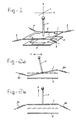
- Figure 1 illustrates a first embodiment of a joystick according to the invention.
- Figure 3 illustrates a second embodiment of a joystick according to the invention.
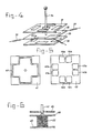
- Figure 4 illustrates a third embodiment of a joystick according to the invention.
- Figure 5 illustrates a pattern of conducting paths for realizing a transmitting coil on the movable printed circuit board and the receiving coils on the fixed printed circuit board.
- Figure 6 illustrates an other way to suspend the movable substrates.
- Figure 7 illustrates a pattern of conducting paths, whereby additional coils for transferring energy are created.
- Figure 8 illustrates an other embodiment of a first substrate, made of massive plate material, and an eventual cooperating second substrate.
- Figure 9 illustrates a cross-section through the first substrate of Figure 8, with the thereto connected control or measuring handle.
- Figure 10 illustrates an embodiment of the second and third substrate destined to be used in combination with a phase-sensitive receiving detection circuit.
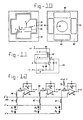
- Figure 11 illustrates a possible oscillator circuit for application in the embodiment of Figure 10.
- Figure 12 illustrates an example of a receiving detection circuit for application together with the components illustrated in Figures 10 and 11.
- Figure 13 illustrates an amended section for the receiving circuit in Figure 12.
- Figure 14 illustrates an alternatively amended section for the receiving circuit in Figure 12.
- Figure 15 illustrates a possible coil conductor path pattern corresponding to the embodiment of the circuit illustrated in Figure 14.
- FIG. 1 illustrates very schematically a control unit which is embodiment in agreement with the principal idea of the invention.
- the control unit comprises two substrates embodied as printed circuit boards 1 and 2.
- the upper printed circuit board 1 is by means of springs 3, 4, 5 and 6 resiliently suspended above the printed circuit board 2, which is installed at a fixed position.
- the upper printed circuit board is, in a way not shown in detail, connected to the control or measuring handle 7.
- the printed circuit board 1 comprises an only schematically indicated transmitting coil 8, whereas the lower printed circuit board 2 comprises four receiving coils, which in the Figure are only partly visible and of which only one is indicated by 9.
- an outer frame for instance in the shape of a bin or box can be applied to install the printed circuit board 2 at a fixed position and to connect furthermore the other ends of the springs 3, 4, 5 and 6.
- Various possibilities are, however, conceivable for such a housing. To simplify the drawing and to make the drawing as clear as possible this frame is not indicated in the Figures.
- control handle which implies that the whole unit is destined to function as control unit, it will be clear that it is also possible to use the unit as measuring unit, in which case the term measuring handle would be more appropriate.
- the transmitting coil 8 is connected to an oscillator circuit such that by means of this transmitting coil 8 an electromagnetic field is generated.
- the presence of this field can be detected through the receiving coils 9 which for that purpose are connected to suitable detection circuits which will be described in more detail lateron.
- suitable detection circuits which will be described in more detail lateron.
- Figure 1 furthermore the directions of an orthogonal system of axes is indicated based on which the movements or displacements of the control handle 7 and therewith of the upper printed circuit board 1 in relation to the lower printed circuit board 2 will be explained.
- the transmitting coil 8 In the neutral position the transmitting coil 8 generates an electromagnet field resulting into a identical signal into each of the receiving coils 9 because the mutually identical receiving coils are all positioned at the same distance and in mutually comparable positions in relation to the transmitting coil.
- knob of the control handle 7 is displaced in X-direction, in other words if the printed circuit board 1 is tilted, taking into account the influence of the suspension springs, around the Y-axis in relation to the neutral position indicated by means of a dash-and-dot line, in a way schematically illustrated in Figur 2a, then, taking into account the transmitting coil generates a constant electromagnetic field, the detection signal in the left hand receiving coil in Figure 2a will increase whereas the detection signal in the right hand receiving coil will decrease, and furthermore the signals in both the front coil and the back coil will not or hardly change.
- control handle 7 is displaced in the Y-direction, in other words is the printed circuit board 1 tilted around the X-axis, then in a similar way the signal from the front (or back) receiving coil will increase whereas the signal from the back (or front) receiving coil will decrease, and furthermore the signals in the left hand and right hand receiving coils will mainly remain the same.
- the suspension of the upper p rinted circuit board 1 by means of a member of springs enables the rotation of the control handle 7 around its own central axis as is schematically indicated in Figure 2c.
- the upper printed circuit board 1 is rotated over an angle ⁇ in relation to the neutral position which is indicated by a dash-and-dot line.
- the transmitting coil has to be embodied such that this rotation causes a change in the flux density in at least one of the receiving coils within the transmitted electromagnetic field. Embodiments of such a transmitting coil will be discussed in detail hereinafter. With a correct embodiments of the transmitting coil a rotation will result into a detectable signal into at least one of the receiving coils.
- the joystick has a large number of freedom degrees.
- the joystick is able to carry out rotations around each of the three axis and is furthermore able to make translational movements along the Z-axis.
- the joystick will be used such that a combined movement is carried out, for instance a rotation around the X-axis, combined with a translation in the Z-direction.
- the receiving coils will generate signals which are dependent of the ultimately obtained position of the first printed circuit board in relation to the second printed circuit board.
- the signals, generated by the receiving coils to a computer in which the basis of the received signals the type of movements, carried out by the control handle, is determined.
- it is furthermore possible to embody the electronic circuit such that this circuit generates one or more output signals by means of which the movement, carried out by the control handle, can be identified in a correct way.
- FIG. 3 illustrates an embodiment of the control unit according to the invention comprising three printed circuit boards 11, 12 and 13.
- the control panel handle 14 is both connected to the upper printed circuit board 11 as well as connected to the lower printed circuit board 13.
- the upper printed circuit board 11 is resiliently suspended by means of four springs 15, 16, 17 and 18.
- the lower printed circuit board 13 is resilient suspended by means of four springs 19, 20 (not visible), 21 and 22. It will be clear that instead of these eight separate springs also combined resilient suspension elements can be applied in a way, which will be discussed in more detail hereinafter.
- the upper printed circuit board 11 comprises a transmitting coil 23 and also the lower printed circuit board 13 comprises a transmitting coil 24.
- the middle printed circuit board 12 comprises four receiving coils 25, which are not all visible and of which only one is indicated by this reference number.
- Both transmitting coils 23 and 24 can be powered such that these transmitting coils are generating opp ositely directed fields. The result thereof is that in the neutral position of the configuration no signal is generated in any one of the receiving coils.
- a rotation of the control handle around the Y-axis in a way similar to the rotation illustrated in Figure 2a will result into a signal of the one polarity in the left hand receiving coil and the signal of the opposite polarity in the right hand receiving coil, whereas in principle the back and front receiving coil will not deliver any signal. If the control handle is tilted around the Y-axis in the other direction then again the left hand and right hand receiving coil will deliver a signal, however, of reversed polarity. A similar combination of signals is obtained during tilting around the X-axis.
- a translational movement in the Z-direction, for instance in the upwards direction, will result in signals of the one polarity from each of the four receiving coils, whereas a translational movement in the Z-direction, in the downwards direction, will result into signals of the opposite polarity from all receiving coils.
- a guiding mechanism can be installed into the opening in the middle fixed position board 12 to guide the control or measuring handle 14.
- An example of such a mechamism is illustrated in Figure 3a and comprises a spherical body 26, set into an annular bearing 27 of which the inner wall is adapted to the spherical shape of the body 26, such that the ball 26 is not able to leave the bearing 27.
- the ball 26 comprises a passage in which the control or measuring handle is inserted.
- the ball 26 is movably contained within the bearing 27 and enables therewith the tilting movement in the X- and Y-direction.
- the handle 14 is able to slide through the passage in the ball 26, so that also a Z-translational movement is possible. The other mentioned movements are with such a mechanism rather restricted.
- the movement of the lower and upper board 11 and 13 in relation to the middle board 12 is now very defined.
- Figure 4 illustrates a further configuration in which also three printed circuit boards are used, i.e. the printed circuit boards 31, 32 and 33.
- the upper and lower board 31 respectively 33 are installed at a fixed position and the middle printed circuit board 32 is connected to the control handle 34.
- the middle printed circuit board 32 is resiliently suspended by means of four springs 35, 36 (not visible), 37, 38.
- the middle printed circuit board 32 comprises a transmitted coil and both the lower and upper printed circuit boards 31 respectively 33 each comprise four receiving coils. Also without a detailed description it will clear that from the signals delivered by the eight receiving coils sufficient data can be derived to draw uniform conclusions about the movement carried out by the control handle 34.
- transmitting coils and receiving coils are discussed without further information about the shape of these coils.
- the transmitting coil is possible to embody the transmitting coil as a series circuit of four separate coils which are positioned directly above the separate receiving coils onto the fixed positioned other printed circuit board.
- four transformers are realized of which the primary windings are connected in series.
- Figure 5 illustrates at the right hand a top view on a printed circuit board 42, comprising four pairs of receiving coils 43a, 43b, 44a, 44b, 45a, 45b, 46a, 46b.
- Figure 5 illustrates at the left hand side a top view on the printed circuit board 41 carrying the transmitting coil 47.
- the receiving coils 43a, ... 46b are in this embodiment shaped as approximately rectangular coils.
- the number of windings can be selected freely by the designer only dependent onto the space and the requ ired field strength.
- the shape of the coils is not restricted to the illustrated rectangular shape.
- the transmitting coil 47 is preferably embodied in the shape of a cross, whereby the larger part of the conductor pattern of each of the legs of the cross in the operational condition positioned directly above corresponding sections of a pair of receiving coils.
- translational movements in the X- and Y-direction are very well detectable with such an embodiment of the coils.
- the flux through the coils 43a and 43b will decrease just as the flux through the coils 45a and 45b.
- the flux through the coils 44a and 44b will hardly not change whereas the flux through the couls 44b and 46a will decrease.
- a similar reasoning can be applied for a translational movement in the X-direction to the right and for the both possible translational movements in the Y-direction.
- FIG. 6 An other possibility to resiliently suspend a movable substrate (or more movable substrates) is illustrated schematically in Figure 6.
- the movable printed cirlcuit board 60 with the thereto conne cted control handle 61 is mounted at the upper end of an helical spring 62 of which the under end is mounted to the section 63 of the housing or frame of the measuring or control unit.
- This embodiment enables both rotational as well as translational movements, whereby dependent on the dimensions and the characteristics of the spring certain movements can be made easier and other movements can be made more difficult.
- the oscillator circuit for powering the transmitting coil is preferably installed onto the printed circuit board carrying also the transmitting coil itself. Therefore, in the embodiment of Figure 1 the oscillator circuit is preferably installed onto the printed circuit board 1 and is connected through suitable conducting paths to the transmitting coil 8. In the embodiment of Figure 3 for instance two separate, however, synchronized oscillator circuits may be present, one on the printed circuit board 11 connected to the coil 23 and one on the printed circuit board 13 connected to the coil 24. The result thereof is a fixed configuration of the transmitter as a whole so that all eventual influences of moving parts on the transmitting frequency are eliminated.
- the oscillator circuit itself has to be powered through a separate multiline cable connected to a fixed positioned power supply source (for instance a battery). However, this connecting cable might be a cable of a very flexible type which in practice does not have any noticeable influence onto the movement characteristic of the control handle.
- the fixed printed circuit board 52 carries a further coil 58 which in the operational condition is connected to an oscillator circuit, installed at the printed circuit board 52 itself or installed somewhere else within the housing of the control unit.
- the coil 58 which can be considered as the primary winding of a transformer, cooperates in the operational position with a coil 59 carried by the movable printed circuit board 51 and to be considered as the secondary coil of the transformer.
- This coil 59 is connected to the oscillator circuit which is symbolized by one integrated circuit 60 installed onto the printed circuit board 51.
- the output of the oscillator circuit is at his turn connected to the transmitting coil 57. Through the coils 58 and 59 high frequency powering energy is tranmitted to the oscillator circuit 60.
- the high frequency energy is rectified and the resulting dc voltage is used for powering the oscillator circuit 60.
- the energy tranfer from the fixed printed circuit board to movable printed circuit board in carried out at a frequency different from the frequency used by the transmitting coil 57 to detect the control handle movements.
- a substrate 70 is illustrated which in this case is not embodied as a printed circuit board but as embodied as a massive metal substrate, for instance made of aluminium.
- This substrate comprises five round openings, i.e. the centrally positioned opening 75 and four openings 71, 72, 73 and 74 surrounding said central opening.
- the openings 71, 72, 73 and 74 are through relatively narrow slots 76, 77, 78 and 79 connected to the central opening 75. It will be clear that this board 70 can be fabricated from plate material in one single punch or blank operation.
- the control handle 80 might be embodied as is illustrated in Figure 9.
- the control handle 80 which is for instance fabricated from a suitable plastic material, comprises a relatively brought base section 75. The edge of this base section is through a suitable adhesvie adhered to the board 70.
- the small passages 81 are indicated destined to snap in the tension springs by means of which the plate 70 is resiliently suspended at a distance of the fixed positioned substrate 82, shown at the left hand side in Figure 8.
- This substrate can be embodied in a usual manner as a printed circuit board comprising a number of annular conductors 83, 84, 85 and 86 operating as receiving coils as well as an annular conductor 87 operating as the primary transformer coil.
- the integrated circuit 88 symbolizes the receiving circuit which in a nonindicated way is connected to the receiving coils and the integrated circuit 89 symbolizes the oscillator circuit which in a non-indicated way is connected to the primary transformer coil.
- the primary transformer coil 87 cooperates with the secondary transformer coil 75, embodied as the central opening in the board 70. Because the board 70 itself is not able to pass any electromagnetic field the whole flux will pass through the opening 75. Because the integrated connection of openings and slots in the plate 70 forms as a whole a short circuited winding surrounded by the material of the plate 70, the sum of the fields through the five openings 71 until 75 should be equal to zero because the short circuited winding creates a counterfield counteracting the field generated by the coil 87.
- the transmitting coil(s), the secondary transformer coil and the substrate are integrated into one plate of a suitable material which can be brought into its ultimate shape by means of a very simple machining operation. Furthermore all the necessary electronic circuits (the transmitting oscillator, the receiving circuit and eventual further signal processing circuits and if necessary also the powering unit) and the connection therebetween can be installed into the fixed printed circuit board. That implies, that this unit can be fabricated with existing production methods in a very simple way which adds to a relatively low cost price of the measuring or control device.
- Figure 11 illustrates the circuit of a prior art three-points oscillator, comprising the transistor T, the capacitors C1, C2, the resistor R and the transmitting coil 91, as well as the second coil 92 w hich is coupled to the transmitting coil 91.
- the oscillator circuit is powered through the connections a and f with the power voltages +V and -V.
- the terminal d has to be connected to earth level.
- the coil 92 supplies through the terminals c, d and e two signals with opposite phase to the respective terminals c ⁇ , d ⁇ and e ⁇ of the receiver circuit which is illustrated in Figure 12.
- a flexible five wire connection has to be present between the substrate 90 and the receiver circuit/power supply unit to supply the power voltages to the oscillator circuit and furthermore to receive and reference signals with opposite phase from the coil 92.
- the receiving circuit comprises three operational amplifiers A x , A y and A z respectively destined to supply signals corresponding to a rotation around the X-axis, a rotation around the Y-axis and a translation in the Z-direction.
- the coils 94 and 96 are in a serial connection with the resistor R1 connected to one input of the amplifier A x .
- the coils 93 and 95 are in a serial connection with the resistor R1 connected to the one input of the amplifier A y .
- the coil 97, which is centrally positioned on the substrate 98 is in serial with the resistor R1 connected to one input of the amplifier A z .
- Each of said amplifiers comprises in a known way the resistors R1, R2 and the capacitor C destined to define the amplification factor of each amplifying stage, i.e. the factor R2/R1. Furthermore said one input of the amplifier A z is through a resistor R3 connected to one of the power supply terminals.
- the mutually counterphased signals are through the terminals c ⁇ and e ⁇ supplied to a first pair of diodes D1, D2, to a second pair of diodes D3, D4 and to a third pair of diodes D5, D6.
- These counterphased signals will take care that half of the time the diodes for the X-direction are conducting whereas the other half of the time the diodes of the Y-direction are conducting. If the diodes are conducting then the corresponding serial pair of detection coils 94, 96 or 93, 95 is connected to the related diode pair and through the coil 92 in a low resistance manner connected to earth level.
- the other side of said pair of coils delivers in such a case a dc component which is proportional to the ac voltage received through the related pair of coils.
- the amplitude of this ac voltage is equal to the sum of the ac voltages in both coils. If now one coil of each pair of coils is counterwinded then the sum of both voltages is in fact the difference between both voltages. That implies that in the neutral position, in which both voltages of each pair will receive the same signal, there is no voltage at the input of the related operational amplifier A x or A y .
- the signal for detecting displacements in the Z-direction are received by the coil 97. Because the Z-translation does not have a zero reference point a resistor R3 is necessary to subtract a predetermined dc current from the received signal. The resistor R3 is therefore used to set the circuit at zero. If an embodiment is used with two receiving substrates, each at one side of the transmitting substrate 90, then it is possible by means of the two coils 97 on each substrate to make a similar serial circuit as is illustrated in Figure 12 for both the X- and Y-direction. In that case it is not necessary to apply the resistor R3.
- a suitable integrated circuit comprising four operational amplifiers in one single housing is for instance the LM348. Together with a relatively small number of further components which can be installed very easily onto the substrate 98 it is therefore possible to realize a complete receiver/detection circuit which delivers at the output X-out, Y-out and Z-out the desired output signals.
- An improvement in the functioning of the circuit can be obtained by adding a passive filter between the serially connected coils and the input of the corresponding operational amplifier stage.
- a passive filter between the serially connected coils and the input of the corresponding operational amplifier stage.
- Such a configuration is only indicated for the X-amplifier stage A x indicated in Figure 13.
- a similar circuit can be used for the Y-stage A y and for the Z-stage AxZz.
- a low pass filter comprising the resistor R4 and the capacitor C3 is inserted between the coil 96 and the input of the operational amplifier A x .
- the further resistor R5 is operating as closing impedance with low resistance.
- each coil comprises two windings, one at the upper surface of the substrate and one at the lower surface thereof, whereby both coils are connected in series.
- the coil 96 is illustrated comprising a winding 96 ⁇ at the upper surface of the substrate 98 ⁇ and a winding 96 ⁇ at the lower surface of the substrate. Both coils are connected in series by means of a connection running through the substrate.
- a similar series circuit of a winding or part thereof at the upper surface of the substrate together with a winding or part thereof at the lower surface of the substrate can be applied of course in case one of the coils is embodied as is illustrated at the right hand side in Figure 5, to widen therewith the number of detection possibilities.
- the configuration around the operational amplifier A x is considered as known to the expert in this field. With this known circuit a double-sided rectifying phase-sensitive detector circuit is realized.
Abstract
Description
- The invention relates to a control or measuring unit of the joystick-type.
- A unit of this type is described in the EP-A- 0,166,467. In this prior art unit the transmitting coil and receiving coils are made onto the substrate which is located at a fixed position. The control or measuring means, in this case embodied as a handle, carries a ferrit body which in the neutral position is located centrally within the transmitting coil. If the control handle and therewith said ferrit body is moved from the neutral position, then the flux in one or more of the receiving coils will change resulting into corresponding changing output signals of the receiving coils, which output signals can be used to detect the direction of movement of the ferrit body, respectively the control handle.
- A disadvantage of the use of ferromagnetic materials or ferrit materials is the fact that the relation between the field strength and induction (the so-called B-H curve) is not linear therefore imposing restrictions on the signal amplitude. Said non-linear B-H relation forms a source of inaccuracies, because this relation is dependent on various factorsd (time, temperature, hysteresis effect, remanence). Also on the long term this non-linear curve may result into a drifting signal transfer leading to an inaccurate signal detection.
- A further disadvantage is that this prior art joystick has in principle only two freedom degrees for the control handle movement, that means two freedom degrees in which the movement can be detected, i.e. a rotation around the X-axis and a rotation around the Y-axis, whereby the imaginary X-Y-plane runs through the point of rotation of the control handle and is perpendicular to said control handle in the neutral position thereof. In many cases there is a need for more freedom degrees to be able to generate a corresponding larger number of various signals. In other cases the measuring unit will be embodied such that the unit can be used for measuring the residual function of handicapped users. Thereby it is important that other rotational or translation movements different from the usual x-rotation and y-rotation of the joystick are measurable.
- An object of the invention is now to eliminate these disadvantages or at least to reduce said disadvantages.
- In agreement with said object the invention now provides a control or measuring unit in
claim 1 of this application. - It is remarked that a switching unit, comprising two mutually movable substrates carry ing combinations of transmitting and receiving coils is described in the US-A- 4,425,511. Although this prior art unit does not comprise ferromagnetic bodies or ferrit bodies, resulting into the therewith corresponding advantages, the control means of this prior art unit is only movable in one direction, i.e. the unit has only one degree of freedom, and furthermore the various coils and the therewith connected detection circuit are embodied such that only the movement according to this one degree of freedom can be detected.
- For generating the electromagnetic field the tranmitting coil has to be connected to an oscillator circuit receiving energy from a suited power supply source. Although it is certainly conceivable to install an oscillator circuit together with a small battery onto the first substrate (and eventually on the third substrate) it will be clear that the presence of the battery will induce heavy rejections. It is therefore preferable that the energy for generating the electromagnetic field is supplied by an oscillator circuit installed onto the first substrate and connected to the transmitting coil or transmitting coils through conductors onto said substrate, and connected with a power supply source at a fixed position through flexible conductors between the substrate and the fixedly positioned power supply source.
- In case the application of a flexible connection between the movable substrate and the power supply source, installed at a fixed position, meets objections then these objections can be eliminated in that the energy for generating the electromagnetic field is supplied by an oscillator circuit installed onto the second or third substrate and coupled through a transformer circuit comprising a primary winding on the second or third substrate and a secondary winding on the first substrate, to the transmitting coil(s) onto the first substrate.
- A rather simple embodiment of the first substrate (and eventually of the third substrate) is characterized in that the secondary coil, the transmitting coils and the conductors running therebetween are realized by means of an electrically conducting first respectively third substrate of non-ferro magnetic material, in which at the coil locations openings are made, the shape and dimensions of which are corresponding to the shape and dimensions of the respective coil, whereby the openings, realizing said transmitting coils, are through slots connected to an opening by means of which the secondary transformer coil is realized.
- The fabrication process of the first (and eventually third) substrate is thereby reduced to a simple blank or punch operation.
- To obtain an at least approximate linear variation in the signal, especially during rotation of the first substrate around the central axis of the control handle (rotation in the X-Y-plane) preferably each transmitting coil is divided into a number of coil sections, the number of which corresponding to the number of receiving coils and each section cooperating with one receiving coil, or by each coil section comprises a stretch which in the neutral position of the unit runs parallel to part of the cooperating receiving coil, and furthermore conducting paths through which said stretches are mutually coupled.
- The disadvantage of the restricted number of freedom degrees can be eliminated in various ways. A proposed embodiment, comprising a first substrate with transmitting coil(s) and a second substrate with receiving coils, installed at a fixed position, is characterized in that the spring forces biasing the control or measuring handle towards the neutral position, are generated by tension springs attached between attachment points on the first substrate and attachment points on the frame or housing of the control are measuring unit. The use of a number of tension coils, preferably acting into one plane, at least in the neutral position of the unit, has the advantage that rotations around each of the X, Y an d Z-axes are possible, that the control handle is movable in a direction parallel to itself in each of the axes directions and also combined translational and rotational movements are possible.
- A further embodiment, proposed in relation to an extension of the number of freedom degrees, is characterized by the spring forces for biasing the control or measuring handle towards a neutral position are generated by a cylindrical helical spring, one end of which is attached to the underside of the control or measuring handle and the other end of which is attached at a fixed position to the frame of housing of the control or measuring unit such that the central axis of this cylindrical helical coil coincides with the central axis of the control or measuring handle in the neutral position thereof.
- Also in this embodiment a rotation around the X and Y-axis is possible as well as a translational movement in the Z-direction, whereas dependent onto the spring characteristic also a rotation around the Z-axis and in a restricted manner also a translational movement in the X and Y-direction are possible. Although the movement possibilities are in this case rather restricted, the construction is very simple.
- The invention will now be explained in more detail with reference to the attached drawings.
- Figure 1 illustrates a first embodiment of a joystick according to the invention.
- The Figures 2a, 2b and 2c illustrate various movement possibilities of the joystick in Figure 1.
- Figure 3 illustrates a second embodiment of a joystick according to the invention.
- Figure 4 illustrates a third embodiment of a joystick according to the invention.
- Figure 5 illustrates a pattern of conducting paths for realizing a transmitting coil on the movable printed circuit board and the receiving coils on the fixed printed circuit board.
- Figure 6 illustrates an other way to suspend the movable substrates.
- Figure 7 illustrates a pattern of conducting paths, whereby additional coils for transferring energy are created.
- Figure 8 illustrates an other embodiment of a first substrate, made of massive plate material, and an eventual cooperating second substrate.
- Figure 9 illustrates a cross-section through the first substrate of Figure 8, with the thereto connected control or measuring handle.
- Figure 10 illustrates an embodiment of the second and third substrate destined to be used in combination with a phase-sensitive receiving detection circuit.
- Figure 11 illustrates a possible oscillator circuit for application in the embodiment of Figure 10.
- Figure 12 illustrates an example of a receiving detection circuit for application together with the components illustrated in Figures 10 and 11.
- Figure 13 illustrates an amended section for the receiving circuit in Figure 12.
- Figure 14 illustrates an alternatively amended section for the receiving circuit in Figure 12.
- Figure 15 illustrates a possible coil conductor path pattern corresponding to the embodiment of the circuit illustrated in Figure 14.
- Figure 1 illustrates very schematically a control unit which is embodiment in agreement with the principal idea of the invention. The control unit comprises two substrates embodied as printed
circuit boards circuit board 1 is by means ofsprings circuit board 2, which is installed at a fixed position. The upper printed circuit board is, in a way not shown in detail, connected to the control or measuringhandle 7. Furthermore the printedcircuit board 1 comprises an only schematically indicated transmittingcoil 8, whereas the lowerprinted circuit board 2 comprises four receiving coils, which in the Figure are only partly visible and of which only one is indicated by 9. It will be clear that an outer frame, for instance in the shape of a bin or box can be applied to install the printedcircuit board 2 at a fixed position and to connect furthermore the other ends of thesprings - Although in the following description the word control handle will be used which implies that the whole unit is destined to function as control unit, it will be clear that it is also possible to use the unit as measuring unit, in which case the term measuring handle would be more appropriate.
- In a way, which will be described in more detail lateron, the transmitting
coil 8 is connected to an oscillator circuit such that by means of this transmittingcoil 8 an electromagnetic field is generated. The presence of this field can be detected through thereceiving coils 9 which for that purpose are connected to suitable detection circuits which will be described in more detail lateron. In the following reference is made shortly to the left, right, front and back receiving coil, whereby in relation to these terms reference is made to the situation illustrated in Figure 1. - In Figure 1 furthermore the directions of an orthogonal system of axes is indicated based on which the movements or displacements of the
control handle 7 and therewith of the upper printedcircuit board 1 in relation to the lowerprinted circuit board 2 will be explained. - In the neutral position the transmitting
coil 8 generates an electromagnet field resulting into a identical signal into each of the receivingcoils 9 because the mutually identical receiving coils are all positioned at the same distance and in mutually comparable positions in relation to the transmitting coil. - If the knob of the
control handle 7 is displaced in X-direction, in other words if the printedcircuit board 1 is tilted, taking into account the influence of the suspension springs, around the Y-axis in relation to the neutral position indicated by means of a dash-and-dot line, in a way schematically illustrated in Figur 2a, then, taking into account the transmitting coil generates a constant electromagnetic field, the detection signal in the left hand receiving coil in Figure 2a will increase whereas the detection signal in the right hand receiving coil will decrease, and furthermore the signals in both the front coil and the back coil will not or hardly change. - If the
control handle 7 is displaced in the Y-direction, in other words is the printedcircuit board 1 tilted around the X-axis, then in a similar way the signal from the front (or back) receiving coil will increase whereas the signal from the back (or front) receiving coil will decrease, and furthermore the signals in the left hand and right hand receiving coils will mainly remain the same. - Both during the tilting around Y-axis as well as during the tilting around X-axis the four
springs - Because of the suspension of the upper printed
circuit board 1 by means of four springs as schematically indicated in Figure 1, it is furthermore possible to move thecontrol handle 7 up and down in the Z-direction as is schematically indicated in Figure 2b. During an upwards displacement of thecontrol handle 7 from the neutral position, indicated by a dash-and-dot line in the Figure, the distance between bothprinted circuit boards coils 9. A downwards displacement of the control handle 7 in relation to the neutral position will result into a decrease of the distance between both printedcircuit boards coils 9 will increase proportionally. - The suspension of the upper p
rinted circuit board 1 by means of a member of springs enables the rotation of the control handle 7 around its own central axis as is schematically indicated in Figure 2c. In this Figure the upper printedcircuit board 1 is rotated over an angle φ in relation to the neutral position which is indicated by a dash-and-dot line. To be able to detect such a rotation the transmitting coil has to be embodied such that this rotation causes a change in the flux density in at least one of the receiving coils within the transmitted electromagnetic field. Embodiments of such a transmitting coil will be discussed in detail hereinafter. With a correct embodiments of the transmitting coil a rotation will result into a detectable signal into at least one of the receiving coils. - Because printed circuit boards, one of which is resiliently suspended in relation to the other, are used to realisze this joystick, the joystick has a large number of freedom degrees. The joystick is able to carry out rotations around each of the three axis and is furthermore able to make translational movements along the Z-axis. In principle it is furthermore possible to carry out translational movements along the X-axis and along the Y-axis, but because the user applies an excentrical force onto the control handle in relation to the center of influence of all the suspension coils 3, 4, 5 and 6 the user should have to do his best to create a pure translational movement. However, it is certainly not impossible and such a translational movement falls, certainly in combination with other movements, within the application possibilities of the joystick according to the invention.
- In many cases the joystick will be used such that a combined movement is carried out, for instance a rotation around the X-axis, combined with a translation in the Z-direction. In that case the receiving coils will generate signals which are dependent of the ultimately obtained position of the first printed circuit board in relation to the second printed circuit board. It is also possible to supply the signals, generated by the receiving coils, to a computer in which the basis of the received signals the type of movements, carried out by the control handle, is determined. It is furthermore possible to embody the electronic circuit such that this circuit generates one or more output signals by means of which the movement, carried out by the control handle, can be identified in a correct way. However, it is also possible in a rather simple manner by adding a third printed circuit board to significantly decrease the necessary electronic circuits or the necessary computer capacity, or even completely eliminate the necessary circuits or necessary capacity.
- Figure 3 illustrates an embodiment of the control unit according to the invention comprising three printed
circuit boards circuit board 11 as well as connected to the lower printedcircuit board 13. In the central section of the middle printedcircuit board 12 an opening is made, the dimensions of which are sufficient to be able to move the control handle without any disturbance. The upper printedcircuit board 11 is resiliently suspended by means of foursprings circuit board 13 is resilient suspended by means of foursprings 19, 20 (not visible), 21 and 22. It will be clear that instead of these eight separate springs also combined resilient suspension elements can be applied in a way, which will be discussed in more detail hereinafter. - The upper printed
circuit board 11 comprises a transmittingcoil 23 and also the lower printedcircuit board 13 comprises a transmittingcoil 24. The middle printedcircuit board 12 comprises four receivingcoils 25, which are not all visible and of which only one is indicated by this reference number. - Both transmitting
coils - A translational movement in the Z-direction, for instance in the upwards direction, will result in signals of the one polarity from each of the four receiving coils, whereas a translational movement in the Z-direction, in the downwards direction, will result into signals of the opposite polarity from all receiving coils.
- If desired a guiding mechanism can be installed into the opening in the middle
fixed position board 12 to guide the control or measuringhandle 14. An example of such a mechamism is illustrated in Figure 3a and comprises aspherical body 26, set into anannular bearing 27 of which the inner wall is adapted to the spherical shape of thebody 26, such that theball 26 is not able to leave thebearing 27. Theball 26 comprises a passage in which the control or measuring handle is inserted. Theball 26 is movably contained within thebearing 27 and enables therewith the tilting movement in the X- and Y-direction. Furthermore thehandle 14 is able to slide through the passage in theball 26, so that also a Z-translational movement is possible. The other mentioned movements are with such a mechanism rather restricted. On the other hand, however, the movement of the lower andupper board middle board 12 is now very defined. - Figure 4 illustrates a further configuration in which also three printed circuit boards are used, i.e. the printed
circuit boards lower board 31 respectively 33 are installed at a fixed position and the middle printedcircuit board 32 is connected to the control handle 34. To give the control handle 34 the necessary freedom of movement an opening of sufficient dimensions is made in the central station of the upper printedcircuit board 31. The middle printedcircuit board 32 is resiliently suspended by means of foursprings 35, 36 (not visible), 37, 38. The middle printedcircuit board 32 comprises a transmitted coil and both the lower and upper printedcircuit boards 31 respectively 33 each comprise four receiving coils. Also without a detailed description it will clear that from the signals delivered by the eight receiving coils sufficient data can be derived to draw uniform conclusions about the movement carried out by the control handle 34. - Above in general transmitting coils and receiving coils are discussed without further information about the shape of these coils. In principle it is possible to embody the transmitting coil as a series circuit of four separate coils which are positioned directly above the separate receiving coils onto the fixed positioned other printed circuit board. Therewith in fact four transformers are realized of which the primary windings are connected in series.
- Figure 5 illustrates at the right hand a top view on a printed
circuit board 42, comprising four pairs of receivingcoils circuit board 41 carrying the transmittingcoil 47. The receivingcoils 43a, ... 46b are in this embodiment shaped as approximately rectangular coils. Of course the number of windings can be selected freely by the designer only dependent onto the space and the requ ired field strength. Also the shape of the coils is not restricted to the illustrated rectangular shape. - The transmitting
coil 47 is preferably embodied in the shape of a cross, whereby the larger part of the conductor pattern of each of the legs of the cross in the operational condition positioned directly above corresponding sections of a pair of receiving coils. With such a non-rotation symmetrical embodiment of the transmitting coil it is possible to detect not only tilting movements around the X- and Y-axis and a translational movement in the Z-direction, but also a tilting around the Z-axis in an unambiguous way. During rotation around the Z-axis for instance in the clockwise direction the flux in all thecoils coils coils coils coils 43a, ... 46b will increase or decrease in a similar way dependent on the direction of the movement. - Also translational movements in the X- and Y-direction are very well detectable with such an embodiment of the coils. During a translation in the X-direction, for instance to the left in Figure 5, the flux through the
coils 43a and 43b will decrease just as the flux through thecoils coils 44a and 44b will hardly not change whereas the flux through the couls 44b and 46a will decrease. A similar reasoning can be applied for a translational movement in the X-direction to the right and for the both possible translational movements in the Y-direction. - Up to now it is postulated that the movable printed circuit board is suspended by means of four tension springs, which are connected to the four edges of the printed circuit board. However, it will be clear that this is only one of the possible solutions to create a resilient suspension of the printed circuit board.
- If four tension springs are applied in the way illustrated in Figure 1, and indicated by 3, 4, 5 and 6, which springs all have the same tension strength, and are positioned such that the direction of the spring force runs through the point where the control handle 7 is connected to the printed
circuit board 1, then a tilting movement around the X-axis can be carried out with the same ease as a tilting movement around the Y-axis. - However, by selecting the direction of the springs in a different way the tilting or rotation around one of these axes can be made easier than the rotation or tilting around the respective other axis. Also a variation in tension strength was influence onto the movement characteristic of the control handle. By a proper choice of the direction of the spring force, the point of attachment and the tension strength of each of the tension springs it is possible to exercise influence onto the movements to be carried out by the control handle.
- In case there are two movable printed circuit boards in the configuration, as in the case of the embodiment illustrated in Figure 3, it is furthermore possible to delete a number of the eight springs, illustrated in this embodiment, with the consequence that movements in certain directions will be enhanced, whereas movements in other directions are made more difficult. It will be clear that omitting for instance the
springs - An other possibility to resiliently suspend a movable substrate (or more movable substrates) is illustrated schematically in Figure 6. The movable printed
cirlcuit board 60 with the thereto conne cted control handle 61 is mounted at the upper end of anhelical spring 62 of which the under end is mounted to thesection 63 of the housing or frame of the measuring or control unit. This embodiment enables both rotational as well as translational movements, whereby dependent on the dimensions and the characteristics of the spring certain movements can be made easier and other movements can be made more difficult. - The oscillator circuit for powering the transmitting coil is preferably installed onto the printed circuit board carrying also the transmitting coil itself. Therefore, in the embodiment of Figure 1 the oscillator circuit is preferably installed onto the printed
circuit board 1 and is connected through suitable conducting paths to the transmittingcoil 8. In the embodiment of Figure 3 for instance two separate, however, synchronized oscillator circuits may be present, one on the printedcircuit board 11 connected to thecoil 23 and one on the printedcircuit board 13 connected to thecoil 24. The result thereof is a fixed configuration of the transmitter as a whole so that all eventual influences of moving parts on the transmitting frequency are eliminated. The oscillator circuit itself has to be powered through a separate multiline cable connected to a fixed positioned power supply source (for instance a battery). However, this connecting cable might be a cable of a very flexible type which in practice does not have any noticeable influence onto the movement characteristic of the control handle. - If, however, for one reason or another the presence of such a connecting cable between the movable printed circuit board or printed circuit boards and a fixed position within the frame of the control unit meets objections, then it is also possible to realize the transmissions of powering energy to the oscillator circuit through high frequency energy transmission from a fixed positioned oscillator unit to the transmitting coil through the air. An example of a movable printed
circuit board 51 carrying the transmittingcoil 57 and a corresponding printedcircuit board 52 carrying the receiving coils 53, 54, 55 and 56, installed at a fixed position, is schematically illustrated in Figure 7. The transmitting and receiving coils are in this case embodied by means of one single winding. The fixed printedcircuit board 52 carries afurther coil 58 which in the operational condition is connected to an oscillator circuit, installed at the printedcircuit board 52 itself or installed somewhere else within the housing of the control unit. Thecoil 58, which can be considered as the primary winding of a transformer, cooperates in the operational position with acoil 59 carried by the movable printedcircuit board 51 and to be considered as the secondary coil of the transformer. Thiscoil 59 is connected to the oscillator circuit which is symbolized by one integratedcircuit 60 installed onto the printedcircuit board 51. The output of the oscillator circuit is at his turn connected to the transmittingcoil 57. Through thecoils oscillator circuit 60. The high frequency energy is rectified and the resulting dc voltage is used for powering theoscillator circuit 60. Preferably, although certainly not necessarily, the energy tranfer from the fixed printed circuit board to movable printed circuit board in carried out at a frequency different from the frequency used by the transmittingcoil 57 to detect the control handle movements. - It is also possible to install the oscillator circuit at the fixed printed
circuit board 52 and to transfer the high frequency energy through thetransformer 58/59 to the transmittingcoil 57, which in this case is directly connected to thetransformer coil 59, onto the same frequency as the frequency of the electromagnet field generated by the transmittingcoil 57. In that case the configuration of the printedcircuit board 51 can be simplified in a manner as illustrated in Figure 8. - At the right hand side in Figure 8 a
substrate 70 is illustrated which in this case is not embodied as a printed circuit board but as embodied as a massive metal substrate, for instance made of aluminium. This substrate comprises five round openings, i.e. the centrally positionedopening 75 and fouropenings openings narrow slots central opening 75. It will be clear that thisboard 70 can be fabricated from plate material in one single punch or blank operation. - The control handle 80 might be embodied as is illustrated in Figure 9. The control handle 80, which is for instance fabricated from a suitable plastic material, comprises a relatively brought
base section 75. The edge of this base section is through a suitable adhesvie adhered to theboard 70. - Both in Figure 8 as well as in Figure 9 the
small passages 81 are indicated destined to snap in the tension springs by means of which theplate 70 is resiliently suspended at a distance of the fixed positionedsubstrate 82, shown at the left hand side in Figure 8. This substrate can be embodied in a usual manner as a printed circuit board comprising a number ofannular conductors annular conductor 87 operating as the primary transformer coil. The integrated circuit 88 symbolizes the receiving circuit which in a nonindicated way is connected to the receiving coils and theintegrated circuit 89 symbolizes the oscillator circuit which in a non-indicated way is connected to the primary transformer coil. - The
primary transformer coil 87 cooperates with thesecondary transformer coil 75, embodied as the central opening in theboard 70. Because theboard 70 itself is not able to pass any electromagnetic field the whole flux will pass through theopening 75. Because the integrated connection of openings and slots in theplate 70 forms as a whole a short circuited winding surrounded by the material of theplate 70, the sum of the fields through the fiveopenings 71 until 75 should be equal to zero because the short circuited winding creates a counterfield counteracting the field generated by thecoil 87. That implies, that through each of the fouropenings 71 until 74 a passage will be guided in the direction opposite the flux direction through thecentral opening 75, whereby the total flux through thecentral opening 75 will be divided into four sub-flexes each running back through one of the fouropenings 71 until 74. - In this embodiment the transmitting coil(s), the secondary transformer coil and the substrate are integrated into one plate of a suitable material which can be brought into its ultimate shape by means of a very simple machining operation. Furthermore all the necessary electronic circuits (the transmitting oscillator, the receiving circuit and eventual further signal processing circuits and if necessary also the powering unit) and the connection therebetween can be installed into the fixed printed circuit board. That implies, that this unit can be fabricated with existing production methods in a very simple way which adds to a relatively low cost price of the measuring or control device.
- In the following embodiment of the transmitting circuit and the detection/receiving circuit will be discussed with reference to the Figures 10 until 12. In said Figures similar components are indicated by the same reference numbers.
- In Figure 10 the
first substrate 90 carrying the transmittingcoil 91 and afurther coil 92 is illustrated at the left hand whereas at the right hand thesecond substrate 98 carrying the receiving coils 93 until 97 is illustrated. - Figure 11 illustrates the circuit of a prior art three-points oscillator, comprising the transistor T, the capacitors C₁, C₂, the resistor R and the transmitting
coil 91, as well as the second coil 92 w hich is coupled to the transmittingcoil 91. - In the Figure 10 and 11 the oscillator circuit is apart from the coils, as one circuit indicated by the
dash line 93. For furthe details about this oscillator circuit the attention is drawn to the literature, for instance Electronica Vademecum, Kluwer, page F5.4, F2.1. - The oscillator circuit is powered through the connections a and f with the power voltages +V and -V. The terminal d has to be connected to earth level. The
coil 92 supplies through the terminals c, d and e two signals with opposite phase to the respective terminals cʹ, dʹ and eʹ of the receiver circuit which is illustrated in Figure 12. - It will be clear that in this embodiment a flexible five wire connection has to be present between the
substrate 90 and the receiver circuit/power supply unit to supply the power voltages to the oscillator circuit and furthermore to receive and reference signals with opposite phase from thecoil 92. - In Figure 12 a very schematic lay out of the receiving circuit is illustrated. The receiving circuit comprises three operational amplifiers A x, A y and A z respectively destined to supply signals corresponding to a rotation around the X-axis, a rotation around the Y-axis and a translation in the Z-direction. The
coils coils coil 97, which is centrally positioned on thesubstrate 98 is in serial with the resistor R₁ connected to one input of the amplifier A z. Each of said amplifiers comprises in a known way the resistors R₁, R₂ and the capacitor C destined to define the amplification factor of each amplifying stage, i.e. the factor R₂/R₁. Furthermore said one input of the amplifier A z is through a resistor R₃ connected to one of the power supply terminals. - The mutually counterphased signals, derived from the
coil 92, are through the terminals cʹ and eʹ supplied to a first pair of diodes D₁, D₂, to a second pair of diodes D₃, D₄ and to a third pair of diodes D₅, D₆. These counterphased signals will take care that half of the time the diodes for the X-direction are conducting whereas the other half of the time the diodes of the Y-direction are conducting. If the diodes are conducting then the corresponding serial pair of detection coils 94, 96 or 93, 95 is connected to the related diode pair and through thecoil 92 in a low resistance manner connected to earth level. The other side of said pair of coils delivers in such a case a dc component which is proportional to the ac voltage received through the related pair of coils. The amplitude of this ac voltage is equal to the sum of the ac voltages in both coils. If now one coil of each pair of coils is counterwinded then the sum of both voltages is in fact the difference between both voltages. That implies that in the neutral position, in which both voltages of each pair will receive the same signal, there is no voltage at the input of the related operational amplifier A x or A y. It will be clear that a rotation in the one direction will result into a positive dc voltage and a rotation in the other direction will result into a negative dc voltage at the input of the respective operational amplifier A x or A y. These dc voltage components are amplified by the related amplifier stage with a factor R₂/R₁. Furthermore the voltage is filtered in these amplifier stages because of the presence of the capacitor C, the value of which is together with the value of the resistors R₂ and R₁ selected such that the frequency sensitivity of each stage is restricted to a desired range. If the unit is u sed as control unit, operated by a human operator, then for instance a restriction to ± 10 Hz can be applied. If the unit is used as measuring unit then it will often be necessary to take into account much higher frequencies. - The signal for detecting displacements in the Z-direction are received by the
coil 97. Because the Z-translation does not have a zero reference point a resistor R₃ is necessary to subtract a predetermined dc current from the received signal. The resistor R₃ is therefore used to set the circuit at zero. If an embodiment is used with two receiving substrates, each at one side of the transmittingsubstrate 90, then it is possible by means of the twocoils 97 on each substrate to make a similar serial circuit as is illustrated in Figure 12 for both the X- and Y-direction. In that case it is not necessary to apply the resistor R₃. - A suitable integrated circuit comprising four operational amplifiers in one single housing is for instance the LM348. Together with a relatively small number of further components which can be installed very easily onto the
substrate 98 it is therefore possible to realize a complete receiver/detection circuit which delivers at the output X-out, Y-out and Z-out the desired output signals. - An improvement in the functioning of the circuit can be obtained by adding a passive filter between the serially connected coils and the input of the corresponding operational amplifier stage. Such a configuration is only indicated for the X-amplifier stage A x indicated in Figure 13. A similar circuit can be used for the Y-stage A y and for the Z-stage AxZz. As appears from Figure 13 a low pass filter comprising the resistor R₄ and the capacitor C₃ is inserted between the
coil 96 and the input of the operational amplifier A x. The further resistor R₅ is operating as closing impedance with low resistance. - In the circuits illustrated in the Figures 12 and 13 a one-sided rectification method using the diode pairs D1, D2, etc. is used. However, it is also possible to use double-sided rectification as is illustrated in the embodiment of Figure 14. In Figure 14 only the circuit for the X-direction is illustrated. However, it will be clear that similar circuits can be used for the Y-direction. In the circuit of Figure 14 four
coils coil 96 is illustrated comprising a winding 96ʺ at the upper surface of the substrate 98ʹ and a winding 96ʹ at the lower surface of the substrate. Both coils are connected in series by means of a connection running through the substrate. A similar series circuit of a winding or part thereof at the upper surface of the substrate together with a winding or part thereof at the lower surface of the substrate can be applied of course in case one of the coils is embodied as is illustrated at the right hand side in Figure 5, to widen therewith the number of detection possibilities. The configuration around the operational amplifier A xis considered as known to the expert in this field. With this known circuit a double-sided rectifying phase-sensitive detector circuit is realized. - If a through connection between the upper coil 96ʺ and the lower coil 96ʹ is used together with a separate terminal as is illustrated in Figure 15 then, certainly in case a very
thin substrate 98 is used, the configuration of two identical coils will deliver two identical signals and is therefore very suited to be used in a circuit as illustrated in Figure 4. By applying these identical coils the adjustment procedure for the detection circuit can be simplified. - It will be clear that above only a number of embodiments of the invention are described. The scope of the adjoining claims is, however, not restricted to these embodiments.
Claims (24)
- Control or measuring unit of the joystick-type, comprising- an operating handle (7) subjected to spring forces biasing said handle towards a neutral position,- at least four receiving coils (9) supported by a first, insulating substrate (2), alternatively taking the form of openings (71-74) in a conducting substrate (70), and provided with terminals destined to connect a detector circuit, and- a transmitting coil (8) supported by a second, insulating substrate (1), also alternatively taking the form of openings (71-74) in a conducting substrate (70), and provided with terminals destined to connect a signal transmitter,
wherein- one of said substrates (1) is connected to the operating handle (17) and is together therewith movable in relation to the other substrate (2) which is fixed,- the spring forces act on the operating handle (7) or on the substrate (1) connected to said operating handle such that the operating handle has at least two freedom degrees,- the transmitting coil (8) and receiving coils (9) are shaped and positioned such that during operation, whereby the transmitting coil is connected to said signal transmitter and the receiving coils are connected to said detector circuit, a movement of the operating handle and the thereto connected substrate will result into a unique combination of detector circuit output signals, characteristic for each of the freedom degrees of the operating handle. - Control or measuring unit according to claim 1, characterized in that the unit comprises a third substrate supporting either a number of receiving coils or a second transmitting coil.
- Control or measuring unit according to claim 2, characterized in that the first and third substrate are connected to the operating handle whereby the second substrate is located at a fixed position and comprises an opening for passing the operating handle.
- Control or measuring unit according to claim 2, characterized in that the first and third substrate are located at fixed positions and the second substrate is connected to the operating handle whereby one of the first and third substrates comprises an opening for passing the operating handle.
- Control or measuring unit according to one of the preceding claims, characterized in that the substrate or each of the substrates connected to the operating handle supports a transmitting coil.
- Control or measuring unit according to one of the claims 2-5, characterized in that operating handle guiding means are installed in said opening for passing the operating handle, said guiding means being destined to guide the operating handle such that under all circumstances this handle runs through a fixed imaginary point in relation to the second substrate.
- Control or measuring unit according to claim 6, charac terized in that the control handle guiding means are embodied as a spherical body comprising a passage, running through the centre of said body, the diameter of said passage corresponding to the outside diameter of the control handle, which spherical body is rotatably clamped into an annular holder, connected to the second substrate, the shape of the inner wall of said holder being adapted to the spherical shape of said body.
- Control or measuring unit according to one of the preceding claims, characterized in that the terminals of the transmitting coil(s) are connected to an oscillator circuit supported by the first substrate, said oscillator circuit being connected to a power supply source at a fixed position within the unit through flexible conductors between the substrate and the fixedly positioned power supply source.
- Control or measuring unit according to one of the claims 1-7, characterized in that the terminals of the transmitting coil(s) are connected to the secondary winding of a transformer circuit, the primary winding of which being installed onto the fixedly positioned substrate and being connected to an oscillator circuit.
- Control or measuring unit according to claim 9, characterized in that the first substrate and, in case thereon a transmitting coil is present, also the third substrate comprises a secondary transformer winding, consisting of only one turn and a number of transmitting coils, each comprising only one turn, positioned around the secondary transformer coil and connected therewith through conductors.
- Control or measuring unit according to claim 10, charac terized in that the secondary coil, the transmitting coils and the conductors running therebetween are realized by means of an electrically conducting first or third substrate of nonferro magnetic material, in which at the coil locations openings are made, the shape and dimensions of which are corresponding to the shape and dimensions of the respective coil, whereby the openings, realizing said transmitting coils, are through slots connected to an opening by means of which the secondary transformer coil is realized.
- Control measuring unit according to one of the claims 10 or 11, characterized in that between the secondary tranformer coil and the transmitting coil(s) on the respective substrate a frequency converter circuit is installed for converting the frequency at which the energy is received through the secondary transformer coil into the frequency of the electromagnetic transmitting field.
- Control or measuring unit according to claim 12, charac terized in that said frequency converter circuit is powered by means of a part of the energy received through the secondary transformer coil.
- Control or measuring unit according to one of the preceding claims, characterized in that the transmitting coil(s) is (are) divided into a number of coil sections, said number corresponding to the number of receiving coils, and each section cooperating with one of said receiving coils.
- Control or measuring unit according to claim 14, charac terized in that each coil section comprises a stretch running in the neutral position of the unit parallel to part of the cooperating receiving coil and comprises furthermore conducting paths for coupling the various stretches.
- Control or measuring unit according to claim 14 or 15, characterized in that the shape of he transmitting coil corresponds with the outline of a cross whereby the rectangularly shaped legs are forming the sections cooperating with the also rectangularly shaped receiving coils.
- Control or measuring unit according to one of the claims 8 until 16, characterized in that the primary and secondary winding of the transformer circuit are embodied angularly and concentrically around the control or measuring handle in the neutral position of said handle.
- Control or measuring unit according to one of the preceding claims, comprising a first substrate with transmitting coil(s) and a second, fixedly positioned substrate with receiving coils, characterized in that the spring forces for biasing the control or measuring handle towards a neutral position are generated by tension springs installed between attachment points on the first substrate and attachment point on the frame of the housing of the control or measuring unit.
- Control or measuring unit according to claim 18, charac terized in that four tension coils are used attached to the corners of a rectangularly shaped first substrate.
- Control or measuring unit according to claim 24, charac terized in that the first substrate has a square shape, and that the strength of the springs is mutually equal and that the direction in which those tension springs are acting, is running through the point in which the control or measuring handle is connected to the first substrate.
- Control or measuring unit according to one of the preceding claims, comprising a first and third substrate with transmitting coils and a second fixedly positioned substrate with receiving coils, characterized in that the spring forces for biasing the control or measuring handle towards a neutral position are generated by means of tension springs attached between attachment points onto the first or second substrate and attachment points on the frame or housing of the control or measuring unit.
- Control or measuring unit according to claim 21, charac terized in that a part of the tension springs are attached to the first substrate and an other part is attached to the third substrate.
- Control or measuring unit according to claim 22, charac terized in that two tension springs of equal strength are attached to the first substrate such that the acting direction of both springs is passing through the connection point between the control or measuring handle and the first substrate, and that two tension springs of equal force are attached to the third substrate such that the acting direction of both springs passes through the connection point of the control or measuring handle to the third substrate.
- Control or measuring handle according to one of the preceding claims 1 until 17, characterized in that the spring forces for biasing the control or measuring handle towards a neutral position are generated by a cylindrical helical spring, one end of which is attached to the underside of the control or measuring handle and the other end of which is attached at a fixed position to the frame or housing of the control or measuring unit such that the central axis of this cylindrical helical coil coincides with the central axis of the control or measuring handle in the neutral position thereof.
Priority Applications (1)
| Application Number | Priority Date | Filing Date | Title |
|---|---|---|---|
| AT87202051T ATE62344T1 (en) | 1986-10-27 | 1987-10-26 | STICK. |
Applications Claiming Priority (2)
| Application Number | Priority Date | Filing Date | Title |
|---|---|---|---|
| NL8602697 | 1986-10-27 | ||
| NL8602697A NL8602697A (en) | 1986-10-27 | 1986-10-27 | JOYSTICK. |
Publications (2)
| Publication Number | Publication Date |
|---|---|
| EP0266829A1 EP0266829A1 (en) | 1988-05-11 |
| EP0266829B1 true EP0266829B1 (en) | 1991-04-03 |
Family
ID=19848729
Family Applications (1)
| Application Number | Title | Priority Date | Filing Date |
|---|---|---|---|
| EP87202051A Expired - Lifetime EP0266829B1 (en) | 1986-10-27 | 1987-10-26 | Joystick |
Country Status (6)
| Country | Link |
|---|---|
| US (1) | US4879556A (en) |
| EP (1) | EP0266829B1 (en) |
| JP (1) | JP2840241B2 (en) |
| AT (1) | ATE62344T1 (en) |
| DE (1) | DE3769081D1 (en) |
| NL (1) | NL8602697A (en) |
Families Citing this family (136)
| Publication number | Priority date | Publication date | Assignee | Title |
|---|---|---|---|---|
| US5095302A (en) * | 1989-06-19 | 1992-03-10 | International Business Machines Corporation | Three dimensional mouse via finger ring or cavity |
| US5457368A (en) * | 1993-03-09 | 1995-10-10 | University Of Utah Research Foundation | Mechanical/electrical displacement transducer |
| EP0422589A1 (en) * | 1989-10-12 | 1991-04-17 | Maurer Instruments Ltd | Positioning and tracking device |
| US5631861A (en) | 1990-02-02 | 1997-05-20 | Virtual Technologies, Inc. | Force feedback and texture simulating interface device |
| US5283555A (en) * | 1990-04-04 | 1994-02-01 | Pandigital Corp. | Dimensional continuous motion controller |
| US4994669A (en) * | 1990-07-29 | 1991-02-19 | Stern Michael A | Opto-electrical joystick switch having a resilient, rigidly mounted central shaft |
| WO1992007350A1 (en) * | 1990-10-15 | 1992-04-30 | National Biomedical Research Foundation | Three-dimensional cursor control device |
| US5146566A (en) * | 1991-05-29 | 1992-09-08 | Ibm Corporation | Input/output system for computer user interface using magnetic levitation |
| US5400054A (en) * | 1991-07-12 | 1995-03-21 | Dorst; Gary L. | Manually operable device for indicating position on a display screen |
| JP3206937B2 (en) * | 1991-07-31 | 2001-09-10 | 株式会社ニデック | Joystick mechanism for ophthalmic equipment |
| US5214428A (en) * | 1991-09-18 | 1993-05-25 | Gregory Allen | Data input grid for computer |
| US5889670A (en) | 1991-10-24 | 1999-03-30 | Immersion Corporation | Method and apparatus for tactilely responsive user interface |
| WO1995002860A1 (en) * | 1991-11-25 | 1995-01-26 | Chuang Keh Shih | Variable effort joystick |
| US5228356A (en) * | 1991-11-25 | 1993-07-20 | Chuang Keh Shih K | Variable effort joystick |
| US6906700B1 (en) | 1992-03-05 | 2005-06-14 | Anascape | 3D controller with vibration |
| US6222525B1 (en) | 1992-03-05 | 2001-04-24 | Brad A. Armstrong | Image controllers with sheet connected sensors |
| JP3237927B2 (en) * | 1992-04-30 | 2001-12-10 | 株式会社ニデック | Joystick mechanism for ophthalmic equipment |
| US5508719A (en) * | 1992-05-01 | 1996-04-16 | Ast Research, Inc. | Pressure-actuated pointing device |
| US5293158A (en) * | 1992-05-05 | 1994-03-08 | Alps Electric Co., Ltd. | X-Y direction input device |
| US6100875A (en) * | 1992-09-03 | 2000-08-08 | Ast Research, Inc. | Keyboard pointing device |
| US5790108A (en) | 1992-10-23 | 1998-08-04 | University Of British Columbia | Controller |
| JP2916842B2 (en) * | 1992-11-11 | 1999-07-05 | アルプス電気株式会社 | Screen display control device |
| US5335142A (en) * | 1992-12-21 | 1994-08-02 | Ast Research, Inc. | Portable computer display tilt/swivel mechanism |
| US5355148A (en) * | 1993-01-14 | 1994-10-11 | Ast Research, Inc. | Fingerpoint mouse |
| US5388990A (en) * | 1993-04-23 | 1995-02-14 | The United States Of America As Represented By The Administrator Of The National Aeronautics And Space Administration | Virtual reality flight control display with six-degree-of-freedom controller and spherical orientation overlay |
| US5739811A (en) | 1993-07-16 | 1998-04-14 | Immersion Human Interface Corporation | Method and apparatus for controlling human-computer interface systems providing force feedback |
| US5701140A (en) * | 1993-07-16 | 1997-12-23 | Immersion Human Interface Corp. | Method and apparatus for providing a cursor control interface with force feedback |
| US5721566A (en) * | 1995-01-18 | 1998-02-24 | Immersion Human Interface Corp. | Method and apparatus for providing damping force feedback |
| US6437771B1 (en) | 1995-01-18 | 2002-08-20 | Immersion Corporation | Force feedback device including flexure member between actuator and user object |
| US5734373A (en) * | 1993-07-16 | 1998-03-31 | Immersion Human Interface Corporation | Method and apparatus for controlling force feedback interface systems utilizing a host computer |
| US5767839A (en) * | 1995-01-18 | 1998-06-16 | Immersion Human Interface Corporation | Method and apparatus for providing passive force feedback to human-computer interface systems |
| US5724264A (en) * | 1993-07-16 | 1998-03-03 | Immersion Human Interface Corp. | Method and apparatus for tracking the position and orientation of a stylus and for digitizing a 3-D object |
| US5805140A (en) | 1993-07-16 | 1998-09-08 | Immersion Corporation | High bandwidth force feedback interface using voice coils and flexures |
| US5731804A (en) * | 1995-01-18 | 1998-03-24 | Immersion Human Interface Corp. | Method and apparatus for providing high bandwidth, low noise mechanical I/O for computer systems |
| WO1995008167A1 (en) * | 1993-09-13 | 1995-03-23 | Asher David J | Joystick with membrane sensor |
| US5625576A (en) | 1993-10-01 | 1997-04-29 | Massachusetts Institute Of Technology | Force reflecting haptic interface |
| US5467108A (en) * | 1994-02-15 | 1995-11-14 | Lexmark International, Inc. | Adjustable pointing stick assembly |
| JPH07281823A (en) * | 1994-04-15 | 1995-10-27 | Hosiden Corp | Coordinate input device |
| US5821920A (en) * | 1994-07-14 | 1998-10-13 | Immersion Human Interface Corporation | Control input device for interfacing an elongated flexible object with a computer system |
| US5623582A (en) | 1994-07-14 | 1997-04-22 | Immersion Human Interface Corporation | Computer interface or control input device for laparoscopic surgical instrument and other elongated mechanical objects |
| US5642469A (en) | 1994-11-03 | 1997-06-24 | University Of Washington | Direct-drive manipulator for pen-based force display |
| US5696535A (en) * | 1994-11-17 | 1997-12-09 | International Business Machines Corporation | Graphics display pointer with integrated selection |
| US5576704A (en) * | 1994-12-01 | 1996-11-19 | Caterpillar Inc. | Capacitive joystick apparatus |
| US5943233A (en) | 1994-12-26 | 1999-08-24 | Sharp Kabushiki Kaisha | Input device for a computer and the like and input processing method |
| US6850222B1 (en) | 1995-01-18 | 2005-02-01 | Immersion Corporation | Passive force feedback for computer interface devices |
| US6400352B1 (en) | 1995-01-18 | 2002-06-04 | Immersion Corporation | Mechanical and force transmission for force feedback devices |
| FR2730329B1 (en) * | 1995-02-06 | 1997-03-21 | Sextant Avionique | CONTROL DEVICE FOR USE IN DESIGNATION AND MOVEMENT OF AN OBJECT ON A SCREEN |
| ATE195031T1 (en) * | 1995-03-28 | 2000-08-15 | Penny & Giles Controls Ltd | SIGNAL PROCESSING CIRCUIT FOR AN INDUCTIVE CONTROL STICK |
| US5539478A (en) * | 1995-05-31 | 1996-07-23 | International Business Machines Corporation | Video receiver display and three axis remote control |
| US5691898A (en) | 1995-09-27 | 1997-11-25 | Immersion Human Interface Corp. | Safe and low cost computer peripherals with force feedback for consumer applications |
| US7113166B1 (en) | 1995-06-09 | 2006-09-26 | Immersion Corporation | Force feedback devices using fluid braking |
| US6166723A (en) | 1995-11-17 | 2000-12-26 | Immersion Corporation | Mouse interface device providing force feedback |
| US5687080A (en) * | 1995-06-20 | 1997-11-11 | Ziba Design, Inc. | Multiple axis data input apparatus and method |
| US5598090A (en) * | 1995-07-31 | 1997-01-28 | Caterpillar Inc. | Inductive joystick apparatus |
| US6697748B1 (en) | 1995-08-07 | 2004-02-24 | Immersion Corporation | Digitizing system and rotary table for determining 3-D geometry of an object |
| US5959613A (en) | 1995-12-01 | 1999-09-28 | Immersion Corporation | Method and apparatus for shaping force signals for a force feedback device |
| US6025832A (en) * | 1995-09-29 | 2000-02-15 | Kabushiki Kaisha Toshiba | Signal generating apparatus, signal inputting apparatus and force-electricity transducing apparatus |
| US6639581B1 (en) | 1995-11-17 | 2003-10-28 | Immersion Corporation | Flexure mechanism for interface device |
| US5825308A (en) | 1996-11-26 | 1998-10-20 | Immersion Human Interface Corporation | Force feedback interface having isotonic and isometric functionality |
| US6704001B1 (en) | 1995-11-17 | 2004-03-09 | Immersion Corporation | Force feedback device including actuator with moving magnet |
| JP2939795B2 (en) * | 1995-11-24 | 1999-08-25 | 株式会社ナナオ | Video monitor adjustment system |
| JPH09161617A (en) * | 1995-11-30 | 1997-06-20 | Sega Enterp Ltd | Switch device |
| WO1997020305A1 (en) | 1995-11-30 | 1997-06-05 | Virtual Technologies, Inc. | Tactile feedback man-machine interface device |
| US5956484A (en) * | 1995-12-13 | 1999-09-21 | Immersion Corporation | Method and apparatus for providing force feedback over a computer network |
| US6219032B1 (en) | 1995-12-01 | 2001-04-17 | Immersion Corporation | Method for providing force feedback to a user of an interface device based on interactions of a controlled cursor with graphical elements in a graphical user interface |
| US7027032B2 (en) | 1995-12-01 | 2006-04-11 | Immersion Corporation | Designing force sensations for force feedback computer applications |
| US8508469B1 (en) | 1995-12-01 | 2013-08-13 | Immersion Corporation | Networked applications including haptic feedback |
| US6147674A (en) | 1995-12-01 | 2000-11-14 | Immersion Corporation | Method and apparatus for designing force sensations in force feedback computer applications |
| US6028593A (en) | 1995-12-01 | 2000-02-22 | Immersion Corporation | Method and apparatus for providing simulated physical interactions within computer generated environments |
| US6859819B1 (en) | 1995-12-13 | 2005-02-22 | Immersion Corporation | Force feedback enabled over a computer network |
| US6161126A (en) * | 1995-12-13 | 2000-12-12 | Immersion Corporation | Implementing force feedback over the World Wide Web and other computer networks |
| US6078308A (en) | 1995-12-13 | 2000-06-20 | Immersion Corporation | Graphical click surfaces for force feedback applications to provide user selection using cursor interaction with a trigger position within a boundary of a graphical object |
| US5684512A (en) * | 1996-05-20 | 1997-11-04 | Schoch; Paul T. | Ergonomic apparatus for controlling video or computer equipment |
| US5767840A (en) * | 1996-06-28 | 1998-06-16 | International Business Machines Corporation | Six-degrees-of-freedom movement sensor having strain gauge mechanical supports |
| US8674932B2 (en) | 1996-07-05 | 2014-03-18 | Anascape, Ltd. | Image controller |
| US6125385A (en) * | 1996-08-01 | 2000-09-26 | Immersion Corporation | Force feedback implementation in web pages |
| US5990869A (en) * | 1996-08-20 | 1999-11-23 | Alliance Technologies Corp. | Force feedback mouse |
| US6024576A (en) | 1996-09-06 | 2000-02-15 | Immersion Corporation | Hemispherical, high bandwidth mechanical interface for computer systems |
| US7489309B2 (en) | 1996-11-26 | 2009-02-10 | Immersion Corporation | Control knob with multiple degrees of freedom and force feedback |
| US6686911B1 (en) | 1996-11-26 | 2004-02-03 | Immersion Corporation | Control knob with control modes and force feedback |
| GB2321108A (en) * | 1997-01-08 | 1998-07-15 | David Alan Woodfield | Input device for inputting positional information |
| TW445426B (en) * | 1997-05-10 | 2001-07-11 | Acer Peripherals Inc | Capacitance sensing type pointing device |
| US5912659A (en) * | 1997-09-03 | 1999-06-15 | International Business Machines Corporation | Graphics display pointer with integrated selection |
| US6252582B1 (en) * | 1998-08-11 | 2001-06-26 | Varatouch Technology Incorporated | Ergonomic pointing device |
| US5911627A (en) * | 1997-10-23 | 1999-06-15 | Logitech, Inc. | Electromagnetic joystick using varying overlap of coils and conductive elements |
| US6211861B1 (en) | 1998-06-23 | 2001-04-03 | Immersion Corporation | Tactile mouse device |
| JP2000047811A (en) * | 1998-07-27 | 2000-02-18 | Alps Electric Co Ltd | Input device |
| US6181327B1 (en) * | 1998-08-04 | 2001-01-30 | Primax Electronics Ltd | Computer joystick |
| US6246391B1 (en) * | 1998-12-01 | 2001-06-12 | Lucent Technologies Inc. | Three-dimensional tactile feedback computer input device |
| US6501458B2 (en) | 1999-06-30 | 2002-12-31 | Caterpillar Inc | Magnetically coupled input device |
| US6982696B1 (en) | 1999-07-01 | 2006-01-03 | Immersion Corporation | Moving magnet actuator for providing haptic feedback |
| US6480183B1 (en) * | 1999-07-23 | 2002-11-12 | Logitech Europe S.A. | Digital joystick using capacitive sensor |
| JP2001092592A (en) * | 1999-09-20 | 2001-04-06 | Sony Corp | Input device and information processor |
| US7602376B1 (en) | 2000-02-22 | 2009-10-13 | P.I. Engineering, Inc. | Moving dielectric, capacitive position sensor configurations |
| DE10012436A1 (en) * | 2000-03-15 | 2001-10-11 | Volkswagen Ag | Joystick control input device has additional motion for entry and cancellation of functions |
| US6854554B2 (en) | 2000-12-15 | 2005-02-15 | Clark Equipment Company | Joystick steering on power machine with filtered steering input |
| US6724198B2 (en) | 2000-12-21 | 2004-04-20 | G. Burnell Hohl | Inductive sensory apparatus |
| US6445311B1 (en) * | 2000-12-21 | 2002-09-03 | G. Burnell Hohl | Inductive joystick |
| IL143255A (en) | 2001-05-20 | 2015-09-24 | Simbionix Ltd | Endoscopic ultrasonography simulation |
| DE10211392B4 (en) * | 2002-03-15 | 2011-03-24 | Paragon Ag | Operating device and method for detecting the switching position of a shift lever of an operating device |
| EP1514257A4 (en) * | 2002-04-12 | 2015-12-30 | Henry K Obermeyer | Multi-axis joystick and transducer means therefore |
| US6748604B2 (en) * | 2002-05-30 | 2004-06-15 | Finger Fitting Products, Inc. | Glove massager |
| US20040130525A1 (en) * | 2002-11-19 | 2004-07-08 | Suchocki Edward J. | Dynamic touch screen amusement game controller |
| EP1422492A1 (en) * | 2002-11-22 | 2004-05-26 | Mecos Traxler AG | Device for contact-less measurement of distances in multiple directions |
| US6831542B2 (en) * | 2003-02-26 | 2004-12-14 | International Business Machines Corporation | Micro-electromechanical inductive switch |
| US7850456B2 (en) | 2003-07-15 | 2010-12-14 | Simbionix Ltd. | Surgical simulation device, system and method |
| US7400317B2 (en) * | 2003-08-29 | 2008-07-15 | Avago Technologies Ecbu Ip Pte Ltd | Finger navigation system using captive surface |
| US7411576B2 (en) | 2003-10-30 | 2008-08-12 | Sensable Technologies, Inc. | Force reflecting haptic interface |
| US7557796B2 (en) | 2004-12-22 | 2009-07-07 | Delphi Technologies, Inc. | Joystick sensor with two-dimensional image sensing |
| US20060170654A1 (en) | 2005-02-02 | 2006-08-03 | Delphi Technologies, Inc. | No tilt joystick with CCD sensing |
| JP4546894B2 (en) * | 2005-08-04 | 2010-09-22 | 富士通コンポーネント株式会社 | Tactile information presentation actuator |
| US20070035516A1 (en) | 2005-08-09 | 2007-02-15 | Delphi Technologies, Inc. | Joystick sensor with light detection |
| US20070091065A1 (en) * | 2005-10-21 | 2007-04-26 | Misek Brian J | Self-aligning pointing device having ESD protection |
| CN101627411B (en) | 2007-01-16 | 2014-03-19 | 西姆博尼克斯有限公司 | Device and method for simulated image to guide medical procedure |
| US8543338B2 (en) | 2007-01-16 | 2013-09-24 | Simbionix Ltd. | System and method for performing computerized simulations for image-guided procedures using a patient specific model |
| DE102007011064A1 (en) * | 2007-03-07 | 2008-09-11 | Paragon Ag | Operating device and method for generating output signals thereof |
| US20090295724A1 (en) * | 2008-05-28 | 2009-12-03 | Wen-Feng Cheng | Adjustable torque joystick |
| US9870021B2 (en) | 2009-04-15 | 2018-01-16 | SeeScan, Inc. | Magnetic manual user interface devices |
| AT11896U1 (en) | 2010-04-08 | 2011-06-15 | Palfinger Ag | CONTACTLESS ELECTRIC CONTROLLER |
| EP2572259A4 (en) | 2010-05-18 | 2014-10-15 | Seescan Inc | User interface devices, apparatus, and methods |
| US10121617B2 (en) | 2010-08-20 | 2018-11-06 | SeeScan, Inc. | Magnetic sensing user interface device methods and apparatus |
| US10203717B2 (en) | 2010-10-12 | 2019-02-12 | SeeScan, Inc. | Magnetic thumbstick user interface devices |
| US9134817B2 (en) | 2010-11-08 | 2015-09-15 | SeeScan, Inc. | Slim profile magnetic user interface devices |
| TW201222332A (en) * | 2010-11-17 | 2012-06-01 | Kye Systems Corp | Three-dimension control devices of computer input devices |
| EP3043231A1 (en) | 2010-12-02 | 2016-07-13 | SeeScan, Inc. | Magnetically sensed user interface devices |
| US8576170B2 (en) | 2011-01-10 | 2013-11-05 | International Business Machines Corporation | Joystick type computer input device with mouse |
| RU2455678C1 (en) * | 2011-01-13 | 2012-07-10 | Общество С Ограниченной Ответственностью Научно-Производственное Предприятие "Тензосенсор" | Method for electric circuits commutation and multifunctional switch for its implementation |
| US9678577B1 (en) | 2011-08-20 | 2017-06-13 | SeeScan, Inc. | Magnetic sensing user interface device methods and apparatus using electromagnets and associated magnetic sensors |
| DE102011082142A1 (en) * | 2011-09-05 | 2013-03-07 | Continental Automotive Gmbh | operating device |
| WO2014186806A1 (en) | 2013-05-17 | 2014-11-20 | SeeScan, Inc. | User interface devices |
| DE102016206482B4 (en) | 2016-04-18 | 2018-03-08 | Deutsches Zentrum für Luft- und Raumfahrt e.V. | touch sensor |
| DE102016206782A1 (en) * | 2016-04-21 | 2017-10-26 | Micro-Epsilon Messtechnik Gmbh & Co. Kg | Measuring arrangement for the contactless measurement of a relative movement or a relative position and method |
| FR3071076B1 (en) * | 2017-09-13 | 2022-07-08 | Zodiac Aero Electric | CONTROL DEVICE FOR MAN-MACHINE INTERFACE WITH ELECTRO-ACTIVE ELEMENTS |
| JP7281690B2 (en) * | 2018-09-20 | 2023-05-26 | パナソニックIpマネジメント株式会社 | Position detector |
| AU2019427466A1 (en) * | 2019-01-31 | 2021-09-16 | Razer (Asia-Pacific) Pte. Ltd. | Inductive joystick |
| WO2023157299A1 (en) * | 2022-02-21 | 2023-08-24 | 任天堂株式会社 | Input device and controller |
Family Cites Families (15)
| Publication number | Priority date | Publication date | Assignee | Title |
|---|---|---|---|---|
| US3350956A (en) * | 1965-07-06 | 1967-11-07 | Gen Dynamics Corp | Six-degree of freedom integrated controller |
| US3373957A (en) * | 1966-03-28 | 1968-03-19 | Budde Wolfgang | Remote vehicle control |
| US3394611A (en) * | 1966-04-25 | 1968-07-30 | Bell Telephone Labor Inc | Output control device with adjustable self-returning null |
| FR2086527A5 (en) * | 1970-04-01 | 1971-12-31 | Clausin Pierre | |
| US3707093A (en) * | 1970-09-10 | 1972-12-26 | Marotta Scientific Controls | Multi-power control system with single control stick |
| NL8002727A (en) * | 1980-05-12 | 1981-12-16 | Applied Electronics Bv | CONTINUOUS ELECTRIC DRIVING TRADE. |
| US4425511A (en) * | 1981-02-09 | 1984-01-10 | Amnon Brosh | Planar coil apparatus employing a stationary and a movable board |
| US4685678A (en) * | 1982-08-13 | 1987-08-11 | Bally Manufacturing Corporation | Position transducer system for a joystick |
| GB2127134A (en) * | 1982-08-13 | 1984-04-04 | Bally Mfg Corp | Interactive joystick |
| US4584577A (en) * | 1982-10-20 | 1986-04-22 | Brookes & Gatehouse Limited | Angular position sensor |
| US4639667A (en) * | 1983-05-23 | 1987-01-27 | Andresen Herman J | Contactless controllers sensing displacement along two orthogonal directions by the overlap of a magnet and saturable cores |
| GB8322640D0 (en) * | 1983-08-23 | 1983-09-28 | Burgess Micro Switch Co Ltd | Manuallyoperable control mechanism |
| DE3405688A1 (en) * | 1984-02-17 | 1985-08-22 | Paul 4992 Espelkamp Gauselmann | Device with a pivotable joystick, particularly for screen games |
| NL8401391A (en) * | 1984-05-02 | 1985-12-02 | Inductive Control Syst | CONTACTLESS ELECTRICAL CONTROL DEVICE. |
| US4584443A (en) * | 1984-05-14 | 1986-04-22 | Honeywell Inc. | Captive digit input device |
-
1986
- 1986-10-27 NL NL8602697A patent/NL8602697A/en not_active Application Discontinuation
-
1987
- 1987-10-26 EP EP87202051A patent/EP0266829B1/en not_active Expired - Lifetime
- 1987-10-26 DE DE8787202051T patent/DE3769081D1/en not_active Expired - Fee Related
- 1987-10-26 AT AT87202051T patent/ATE62344T1/en not_active IP Right Cessation
- 1987-10-26 US US07/113,245 patent/US4879556A/en not_active Expired - Fee Related
- 1987-10-27 JP JP62271565A patent/JP2840241B2/en not_active Expired - Lifetime
Also Published As
| Publication number | Publication date |
|---|---|
| JPS63170726A (en) | 1988-07-14 |
| DE3769081D1 (en) | 1991-05-08 |
| EP0266829A1 (en) | 1988-05-11 |
| ATE62344T1 (en) | 1991-04-15 |
| JP2840241B2 (en) | 1998-12-24 |
| NL8602697A (en) | 1988-05-16 |
| US4879556A (en) | 1989-11-07 |
Similar Documents
| Publication | Publication Date | Title |
|---|---|---|
| EP0266829B1 (en) | Joystick | |
| EP0137347B1 (en) | A detector circuit for current measurements | |
| US4833919A (en) | Device for measuring displacement | |
| US4223313A (en) | Power transfer circuit | |
| EP0246377A1 (en) | Electrically-variable inductor | |
| US20040196045A1 (en) | Systems and methods useful for detecting presence and / or location of various materials | |
| US20070222437A1 (en) | Device for Locating Metallic Objects and Methods for Adjusting Such a Device | |
| US20020075113A1 (en) | Method and apparatus for transmitting a signal through a power magnetic structure | |
| CA2233879A1 (en) | Ac current sensor | |
| KR930011889B1 (en) | Position detecting device | |
| EP0818021B1 (en) | Inductive joystick and signal processing circuit therefor | |
| GB2217859A (en) | Eddy current measurement of the resistance of thin layers | |
| US3956618A (en) | Mechanical-electrical transducer | |
| US4163189A (en) | Transformer with a ferromagnetic core for d-c and a-c signals | |
| GB2084809A (en) | Printed circuit transformers | |
| EP0278635B1 (en) | Negative feedback power supply apparatus | |
| GB2295459A (en) | Alternating current sensor | |
| WO2004102370A2 (en) | Sensor apparatus | |
| DE3666744D1 (en) | High-frequency wide band transformer circuit | |
| JPS6247730A (en) | Position detecting device | |
| Hall et al. | A computer‐controlled all‐pass phase shift filter for a variable frequency two‐phase ac magnetic susceptometer | |
| SU1328801A1 (en) | Device for obtaining the given values of direct current | |
| SU1288678A1 (en) | Servo device | |
| ES2001118A6 (en) | Electronically adjustable construction inductive element, procedure for its operation and use. | |
| JPS61220018A (en) | Position detector |
Legal Events
| Date | Code | Title | Description |
|---|---|---|---|
| PUAI | Public reference made under article 153(3) epc to a published international application that has entered the european phase |
Free format text: ORIGINAL CODE: 0009012 |
|
| AK | Designated contracting states |
Kind code of ref document: A1 Designated state(s): AT BE CH DE ES FR GB GR IT LI LU NL SE |
|
| 17P | Request for examination filed |
Effective date: 19880915 |
|
| 17Q | First examination report despatched |
Effective date: 19900108 |
|
| GRAA | (expected) grant |
Free format text: ORIGINAL CODE: 0009210 |
|
| AK | Designated contracting states |
Kind code of ref document: B1 Designated state(s): AT BE CH DE ES FR GB GR IT LI LU NL SE |
|
| PG25 | Lapsed in a contracting state [announced via postgrant information from national office to epo] |
Ref country code: IT Free format text: LAPSE BECAUSE OF FAILURE TO SUBMIT A TRANSLATION OF THE DESCRIPTION OR TO PAY THE FEE WITHIN THE PRE;WARNING: LAPSES OF ITALIAN PATENTS WITH EFFECTIVE DATE BEFORE 2007 MAY HAVE OCCURRED AT ANY TIME BEFORE 2007. THE CORRECT EFFECTIVE DATE MAY BE DIFFERENT FROM THE ONE RECORDED.SCRIBED TIME-LIMIT Effective date: 19910403 Ref country code: SE Effective date: 19910403 Ref country code: BE Effective date: 19910403 Ref country code: GR Free format text: LAPSE BECAUSE OF FAILURE TO SUBMIT A TRANSLATION OF THE DESCRIPTION OR TO PAY THE FEE WITHIN THE PRESCRIBED TIME-LIMIT Effective date: 19910403 Ref country code: LI Effective date: 19910403 Ref country code: AT Effective date: 19910403 Ref country code: CH Effective date: 19910403 |
|
| REF | Corresponds to: |
Ref document number: 62344 Country of ref document: AT Date of ref document: 19910415 Kind code of ref document: T |
|
| REF | Corresponds to: |
Ref document number: 3769081 Country of ref document: DE Date of ref document: 19910508 |
|
| ET | Fr: translation filed | ||
| PG25 | Lapsed in a contracting state [announced via postgrant information from national office to epo] |
Ref country code: ES Free format text: LAPSE BECAUSE OF FAILURE TO SUBMIT A TRANSLATION OF THE DESCRIPTION OR TO PAY THE FEE WITHIN THE PRESCRIBED TIME-LIMIT Effective date: 19910714 |
|
| REG | Reference to a national code |
Ref country code: CH Ref legal event code: PL |
|
| PLBE | No opposition filed within time limit |
Free format text: ORIGINAL CODE: 0009261 |
|
| STAA | Information on the status of an ep patent application or granted ep patent |
Free format text: STATUS: NO OPPOSITION FILED WITHIN TIME LIMIT |
|
| 26N | No opposition filed | ||
| EPTA | Lu: last paid annual fee | ||
| PGFP | Annual fee paid to national office [announced via postgrant information from national office to epo] |
Ref country code: NL Payment date: 19981209 Year of fee payment: 12 |
|
| PGFP | Annual fee paid to national office [announced via postgrant information from national office to epo] |
Ref country code: GB Payment date: 19981218 Year of fee payment: 12 |
|
| PGFP | Annual fee paid to national office [announced via postgrant information from national office to epo] |
Ref country code: DE Payment date: 19981221 Year of fee payment: 12 |
|
| PGFP | Annual fee paid to national office [announced via postgrant information from national office to epo] |
Ref country code: FR Payment date: 19981222 Year of fee payment: 12 |
|
| PGFP | Annual fee paid to national office [announced via postgrant information from national office to epo] |
Ref country code: LU Payment date: 19981223 Year of fee payment: 12 |
|
| PG25 | Lapsed in a contracting state [announced via postgrant information from national office to epo] |
Ref country code: GB Free format text: LAPSE BECAUSE OF NON-PAYMENT OF DUE FEES Effective date: 19991026 Ref country code: LU Free format text: LAPSE BECAUSE OF NON-PAYMENT OF DUE FEES Effective date: 19991026 |
|
| PG25 | Lapsed in a contracting state [announced via postgrant information from national office to epo] |
Ref country code: NL Free format text: LAPSE BECAUSE OF NON-PAYMENT OF DUE FEES Effective date: 20000501 |
|
| GBPC | Gb: european patent ceased through non-payment of renewal fee |
Effective date: 19991026 |
|
| PG25 | Lapsed in a contracting state [announced via postgrant information from national office to epo] |
Ref country code: FR Free format text: LAPSE BECAUSE OF NON-PAYMENT OF DUE FEES Effective date: 20000630 |
|
| NLV4 | Nl: lapsed or anulled due to non-payment of the annual fee |
Effective date: 20000501 |
|
| PG25 | Lapsed in a contracting state [announced via postgrant information from national office to epo] |
Ref country code: DE Free format text: LAPSE BECAUSE OF NON-PAYMENT OF DUE FEES Effective date: 20000801 |
|
| REG | Reference to a national code |
Ref country code: FR Ref legal event code: ST |