EP0260726A2 - Passenger entertainment system having direct coupled seat receivers - Google Patents
Passenger entertainment system having direct coupled seat receivers Download PDFInfo
- Publication number
- EP0260726A2 EP0260726A2 EP87200354A EP87200354A EP0260726A2 EP 0260726 A2 EP0260726 A2 EP 0260726A2 EP 87200354 A EP87200354 A EP 87200354A EP 87200354 A EP87200354 A EP 87200354A EP 0260726 A2 EP0260726 A2 EP 0260726A2
- Authority
- EP
- European Patent Office
- Prior art keywords
- seat
- receiver
- seat track
- track
- transmission line
- Prior art date
- Legal status (The legal status is an assumption and is not a legal conclusion. Google has not performed a legal analysis and makes no representation as to the accuracy of the status listed.)
- Granted
Links
Images
Classifications
-
- B—PERFORMING OPERATIONS; TRANSPORTING
- B64—AIRCRAFT; AVIATION; COSMONAUTICS
- B64D—EQUIPMENT FOR FITTING IN OR TO AIRCRAFT; FLIGHT SUITS; PARACHUTES; ARRANGEMENTS OR MOUNTING OF POWER PLANTS OR PROPULSION TRANSMISSIONS IN AIRCRAFT
- B64D11/00—Passenger or crew accommodation; Flight-deck installations not otherwise provided for
- B64D11/0015—Arrangements for entertainment or communications, e.g. radio, television
- B64D11/00155—Individual entertainment or communication system remote controls therefor, located in or connected to seat components, e.g. to seat back or arm rest
-
- B—PERFORMING OPERATIONS; TRANSPORTING
- B64—AIRCRAFT; AVIATION; COSMONAUTICS
- B64C—AEROPLANES; HELICOPTERS
- B64C1/00—Fuselages; Constructional features common to fuselages, wings, stabilising surfaces or the like
- B64C1/18—Floors
- B64C1/20—Floors specially adapted for freight
-
- B—PERFORMING OPERATIONS; TRANSPORTING
- B64—AIRCRAFT; AVIATION; COSMONAUTICS
- B64D—EQUIPMENT FOR FITTING IN OR TO AIRCRAFT; FLIGHT SUITS; PARACHUTES; ARRANGEMENTS OR MOUNTING OF POWER PLANTS OR PROPULSION TRANSMISSIONS IN AIRCRAFT
- B64D11/00—Passenger or crew accommodation; Flight-deck installations not otherwise provided for
- B64D11/06—Arrangements of seats, or adaptations or details specially adapted for aircraft seats
- B64D11/0624—Arrangements of electrical connectors, e.g. for earphone, internet or electric supply
-
- H—ELECTRICITY
- H04—ELECTRIC COMMUNICATION TECHNIQUE
- H04R—LOUDSPEAKERS, MICROPHONES, GRAMOPHONE PICK-UPS OR LIKE ACOUSTIC ELECTROMECHANICAL TRANSDUCERS; DEAF-AID SETS; PUBLIC ADDRESS SYSTEMS
- H04R27/00—Public address systems
Definitions
- the present invention relates to passenger entertainment systems in commercial aircraft and more particularly to a means and method of coupling the individual seat receivers to the passenger entertainment system transmitter.
- Typical commercial airplane entertainment and service systems are hard wired requiring cable and connector interconnection to the seat modules.
- a typical installation requires the installation of permanent wire bundles in aircraft structure routed to convenient locations along the fuselage or beneath the floor.
- the nearest seat module, in a group of seat modules is connected to the permanent wiring and then all remaining seat modules are linked, in a daisy-chain fashion, from one another in succession.
- Interconnecting cables are then required to be protected and concealed in a trough running parallel to the seat tracks.
- Such systems are deficient in the sense that any radical change in seat configuration would require the fabrication of new interconnect cables of the proper length to match the new seat spacing dimensions.
- Seat removal or configuration changes require a labor intensive effort including revision of connect cables, their interconnection, and their protection and removal from the aforementioned trough.
- Preferred embodiments of the present invention provide direct coupling of individual seat receivers through an electrical conductor or plurality of conductors disposed within the seat track which conductors are connected to the passenger entertainment system.
- a conductive probe in the seat leg can make direct connection to a conductive plate extending along the seat track in accordance with a first embodiment, or a plurality of seat conductors may be disposed parallel with and along the length of the seat track itself in accordance with a further embodiment of the invention.
- the direct connection between seat receiver and the conductive transmission line or lines disposed along the length of the seat track may be made by actuation of a seat latch if desired.
- a signal box so installed in the seat track provides direct coupling to seat receivers disposed at various positions along the length of the track without need for a hard wired connection thereby eliminating the problems existent in prior entertainment and service systems which required interconnection of seat receivers on an individual basis.
- a seat track indicated generally at l0 consists of a generally rectangular shaped chamber l2 having a top flap l3 with individual apertures l5 for insertion of seat legs (not shown).
- Insulator strips l7 run parallel with and in contact with the outer sidewalls of rectangular shaped chamber l2. Insulator strips l7 support the parallel extending conductor members l8. As seen in the vertical sectional view of FIG.
- a seat post 20 is inserted through aperture l5 into track l0 with the outer surfaces of conductor strips l8 available for a direct coupling by conductive contact to the power supply and electronics of the individual seat receivers l6.
- a seat receiver l6 may be of the type shown under numeral l6 of U.S. Patent 4,428,078.
- a transmitter 23 of the type shown in U.S. Patent 4,428,078 provides the passenger entertainment signals to the conductive transmission line formed by conductors l8 of FIG. 2.
- a pulley 30 is shown to make and break the conductive coupling connections at 34 through energization and de-energization of spring means 32.
- FIG. 2 a pulley 30 is shown to make and break the conductive coupling connections at 34 through energization and de-energization of spring means 32.
- the seat latch assembly can therefore through pulley 32 make the automatic connection and although a line and pulley is utilized in the embodiment of FIG. 2 other equivalent mechanical means may be utilized between the seat latch assembly (not shown) and the electrical contacts 34 which are made and broken depending upon the connection and disconnection condition of the seat latch.
- a pincer like, spring-loaded contactor mechanism is shown to provide the direct coupling in FIG. 2
- an actual probe makes the direct contact in the embodiment of FIG. 3 with a conductive plate 50 which is in the form of a strip extending parallel with and along the bottom of the seat track l0. Probe 60 which as in the embodiment of FIG.
- conductive plate 50 may be also energized by actuation of the seat latch to make the contact with conductive plate 50 makes and breaks the direct coupling dependent upon the status of the seat latch.
- the conductive plate 50 extending along the bottom of the seat track is required to be insulated on bottom and sides by insulators 52 running along the sides of and underneath the conductive plate member 50.
- seat leg 20 Above conductor probe 60 from which it protrudes, is seat leg 20 which may have the receiver electronics l6 which receiver electronics l6 may be coupled by suitable coupling means shown generally at 62 to the probe 60.
- FIG. 8 With side and sectional views thereof in FIGS. 4-7, there can be seen a seat post l02 and seat frame l03 installed.
- a layer of insulating material l04 is mounted in seat track l0l.
- Direct coupling conductors l05 are supported by layer of insulating material l04, the angled side portion providing self aligning capability with the individual seat group associated conductor l06 and associated holding bracket l07 which is in turn spring mounted in nonconductive housing member l08.
- Each nonconductive housing member l08 includes more than one seat group associated conductor l06 and associated holding bracket l07 thereby providing reliable direct electrical contact. It can be seen that seat group associated conductor l06, spring loaded holding bracket l07 and nonconductive housing member l08 comprises a single assembly which can easily be mounted (or removed from) a seat frame thereby providing easy retrofit capability using any standard aircraft seat.
Abstract
Description
- The present invention relates to passenger entertainment systems in commercial aircraft and more particularly to a means and method of coupling the individual seat receivers to the passenger entertainment system transmitter.
- The patent literature is replete with various types of power distribution systems having current-carrying bars, electrical traps for supplying currents and other current-carrying transmission arrangements. The patent art more specifically is exemplified by U.S. Patent No. 3,603,9l8 which shows an electric power distribution system having a current-carrying bar; U.S. Patent No. 4,032,208 showing a connector for track lighting systems; and U.S. Patent No. 4,083,439 showing a power collection device for electric powered rail cars. An earlier U.S. Patent No. 4,428,078 assigned to The Boeing Company shows transmission of power and multiplex data from a parallel transmission line on the aircraft floor to an air-core multi-turn loop located in the seat leg framework on the seat module. This configuration is unable to provide the power transfer capabilities which the present direct coupled system provides.
- Typical commercial airplane entertainment and service systems are hard wired requiring cable and connector interconnection to the seat modules. A typical installation requires the installation of permanent wire bundles in aircraft structure routed to convenient locations along the fuselage or beneath the floor. The nearest seat module, in a group of seat modules, is connected to the permanent wiring and then all remaining seat modules are linked, in a daisy-chain fashion, from one another in succession. Interconnecting cables are then required to be protected and concealed in a trough running parallel to the seat tracks. Such systems are deficient in the sense that any radical change in seat configuration would require the fabrication of new interconnect cables of the proper length to match the new seat spacing dimensions. Seat removal or configuration changes require a labor intensive effort including revision of connect cables, their interconnection, and their protection and removal from the aforementioned trough.
- Preferred embodiments of the present invention provide direct coupling of individual seat receivers through an electrical conductor or plurality of conductors disposed within the seat track which conductors are connected to the passenger entertainment system. A conductive probe in the seat leg can make direct connection to a conductive plate extending along the seat track in accordance with a first embodiment, or a plurality of seat conductors may be disposed parallel with and along the length of the seat track itself in accordance with a further embodiment of the invention. The direct connection between seat receiver and the conductive transmission line or lines disposed along the length of the seat track may be made by actuation of a seat latch if desired.
- A signal box so installed in the seat track provides direct coupling to seat receivers disposed at various positions along the length of the track without need for a hard wired connection thereby eliminating the problems existent in prior entertainment and service systems which required interconnection of seat receivers on an individual basis.
-
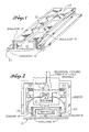
- FIG. l is an isometric view in partial section illustrative of a first embodiment of the invention showing a seat track having parallel extending conductors;
- FIG. 2 is illustrative of the pincer like spring-loaded mechanism for interconnecting the individual seat receiver with the track embodiment of FIG. l;
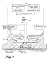
- FIG. 3 is a vertical sectional view of a further embodiment of seat track utilized in the present direct coupling of seat receivers and further illustrative of probe contact to an individual receiver seat track station;
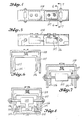
- FIG. 4 is a top plan view of another embodiment of direct coupled seat track receiver comprising a retrofit seat track assembly in accordance with the present invention;
- FIG. 5 is a side view of the embodiment of FIG. 4;
- FIG. 6 is a sectional view taken along the line 6-6 of FIG. 4;
- FIG. 7 is a sectional view of the embodiment of FIG. 4 taken along the lines 7-7 of FIG. 4; and,
- FIG. 8 is a sectional view of an assembly of FIG. 4 showing seat track coupling in detail.
- Turning now to FIG. l and a first embodiment of the present direct coupling of passenger entertainment systems to individual seat receivers, it will be observed that a seat track indicated generally at l0 consists of a generally rectangular shaped chamber l2 having a top flap l3 with individual apertures l5 for insertion of seat legs (not shown). Insulator strips l7 run parallel with and in contact with the outer sidewalls of rectangular shaped chamber l2. Insulator strips l7 support the parallel extending conductor members l8. As seen in the vertical sectional view of FIG. 2 a
seat post 20 is inserted through aperture l5 into track l0 with the outer surfaces of conductor strips l8 available for a direct coupling by conductive contact to the power supply and electronics of the individual seat receivers l6. A seat receiver l6 may be of the type shown under numeral l6 of U.S. Patent 4,428,078. Further a transmitter 23 of the type shown in U.S. Patent 4,428,078 provides the passenger entertainment signals to the conductive transmission line formed by conductors l8 of FIG. 2. In FIG. 2 apulley 30 is shown to make and break the conductive coupling connections at 34 through energization and de-energization of spring means 32. In the illustrated embodiment of FIG. 2 the seat latch assembly can therefore throughpulley 32 make the automatic connection and although a line and pulley is utilized in the embodiment of FIG. 2 other equivalent mechanical means may be utilized between the seat latch assembly (not shown) and theelectrical contacts 34 which are made and broken depending upon the connection and disconnection condition of the seat latch. While a pincer like, spring-loaded contactor mechanism is shown to provide the direct coupling in FIG. 2, an actual probe makes the direct contact in the embodiment of FIG. 3 with aconductive plate 50 which is in the form of a strip extending parallel with and along the bottom of the seat track l0.Probe 60 which as in the embodiment of FIG. 2 may be also energized by actuation of the seat latch to make the contact withconductive plate 50 makes and breaks the direct coupling dependent upon the status of the seat latch. It can also be seen that in the embodiment of FIG. 3 theconductive plate 50 extending along the bottom of the seat track is required to be insulated on bottom and sides by insulators 52 running along the sides of and underneath theconductive plate member 50. Aboveconductor probe 60 from which it protrudes, isseat leg 20 which may have the receiver electronics l6 which receiver electronics l6 may be coupled by suitable coupling means shown generally at 62 to theprobe 60. The aforementioned embodiments of direct coupled passenger entertainment systems to the individual seat receivers eliminates the previous problem of power transfer through inductive coupling between transmission lines in the seat tracks and provides individual direct connections to the seat receivers l6 at the time the seats are installed. - Turning now to the complete seat track assembly showing the direct conductive contact in FIG. 8 with side and sectional views thereof in FIGS. 4-7, there can be seen a seat post l02 and seat frame l03 installed. A layer of insulating material l04 is mounted in seat track l0l. Direct coupling conductors l05 are supported by layer of insulating material l04, the angled side portion providing self aligning capability with the individual seat group associated conductor l06 and associated holding bracket l07 which is in turn spring mounted in nonconductive housing member l08. Each nonconductive housing member l08 includes more than one seat group associated conductor l06 and associated holding bracket l07 thereby providing reliable direct electrical contact. It can be seen that seat group associated conductor l06, spring loaded holding bracket l07 and nonconductive housing member l08 comprises a single assembly which can easily be mounted (or removed from) a seat frame thereby providing easy retrofit capability using any standard aircraft seat.
Claims (4)
direct coupled receiver transmitter means including a seat track transmission line connected between said receiver means associated with each of said plurality of seat units and said transmitter means, said seat track transmission line including a conductor extending parallel with and along the length of the seat track.
an electrically conductive transmission line extending along the length of said seat track and parallel therewith, said electrically conductive transmission line including an electrical insulator strip disposed between an electrically conductive strip and said seat track; and,
electrical connector means disposed between said plurality of receiver means associated with a plurality of seat units distributed along said seat track.
Applications Claiming Priority (2)
| Application Number | Priority Date | Filing Date | Title |
|---|---|---|---|
| US908449 | 1986-09-17 | ||
| US06/908,449 US4763360A (en) | 1986-09-17 | 1986-09-17 | Passenger entertainment system having direct coupled seat receivers |
Publications (3)
| Publication Number | Publication Date |
|---|---|
| EP0260726A2 true EP0260726A2 (en) | 1988-03-23 |
| EP0260726A3 EP0260726A3 (en) | 1989-06-14 |
| EP0260726B1 EP0260726B1 (en) | 1993-01-27 |
Family
ID=25425823
Family Applications (1)
| Application Number | Title | Priority Date | Filing Date |
|---|---|---|---|
| EP87200354A Expired - Lifetime EP0260726B1 (en) | 1986-09-17 | 1987-02-26 | Passenger entertainment system having direct coupled seat receivers |
Country Status (3)
| Country | Link |
|---|---|
| US (1) | US4763360A (en) |
| EP (1) | EP0260726B1 (en) |
| DE (1) | DE3783842T2 (en) |
Cited By (14)
| Publication number | Priority date | Publication date | Assignee | Title |
|---|---|---|---|---|
| EP1626470A2 (en) * | 2004-08-12 | 2006-02-15 | Airbus Deutschland GmbH | Current distribution system for electric supply of rail-mounted installations in an aircraft |
| WO2006122351A1 (en) * | 2005-05-19 | 2006-11-23 | Telezygology Inc | Tracks, power and data blocks and releasable fastening system |
| EP2108584A2 (en) * | 2008-04-12 | 2009-10-14 | Damm, Hans | Attachment rail for airplane seats |
| FR2960665A1 (en) * | 2010-05-28 | 2011-12-02 | Antar Daouk | Signal e.g. power signal transmission system for use in airliner, has main conductor and intermediate conductor that are moved with respect to each other to evolve between first configuration and second configuration |
| WO2014123692A1 (en) * | 2013-02-11 | 2014-08-14 | Ferno-Washington, Inc. | Electrified equipment mounting system |
| US9362610B2 (en) | 2012-02-14 | 2016-06-07 | Ferno-Washington, Inc. | Quick antenna attachment system |
| US9611975B2 (en) | 2013-02-11 | 2017-04-04 | Ferno-Washington, Inc. | Equipment mounting system |
| US9944217B2 (en) | 2013-02-11 | 2018-04-17 | Ferno-Washington, Inc. | Equipment mounting system |
| US10307313B2 (en) | 2013-02-11 | 2019-06-04 | Ferno-Washington, Inc. | Equipment mounting system |
| US10398207B2 (en) | 2014-02-11 | 2019-09-03 | Ferno-Washington, Inc. | Crash-ready, portable, compartmentalization device |
| US10398203B2 (en) | 2014-02-11 | 2019-09-03 | Ferno-Washington, Inc. | Crash-ready, portable, compartmentalization device |
| US10786055B2 (en) | 2014-07-18 | 2020-09-29 | Ferno-Washington, Inc. | Crash-ready, portable, compartmentalization device |
| US11083265B2 (en) | 2014-02-11 | 2021-08-10 | Ferno-Washington, Inc. | Magnetic pouch attachment mechanism with crash stable locking teeth |
| WO2023105424A1 (en) * | 2021-12-07 | 2023-06-15 | Adient Us Llc | Device for automatically electrically connecting and disconnecting an electrical plug of a vehicle seat |
Families Citing this family (67)
| Publication number | Priority date | Publication date | Assignee | Title |
|---|---|---|---|---|
| US4853555A (en) * | 1988-04-21 | 1989-08-01 | The Boeing Company | Electrical power transfer system for aircraft passenger entertainment system |
| US6038426A (en) * | 1996-08-26 | 2000-03-14 | Sony Corporation | System and method for securing a removable seat electronics unit without detachment of the communication cable |
| US5848367A (en) * | 1996-09-13 | 1998-12-08 | Sony Corporation | System and method for sharing a non-volatile memory element as a boot device |
| US6014381A (en) * | 1996-09-13 | 2000-01-11 | Sony Corporation | System and method for distributing information throughout an aircraft |
| US5854591A (en) * | 1996-09-13 | 1998-12-29 | Sony Trans Com, Inc. | System and method for processing passenger service system information |
| US5896129A (en) * | 1996-09-13 | 1999-04-20 | Sony Corporation | User friendly passenger interface including audio menuing for the visually impaired and closed captioning for the hearing impaired for an interactive flight entertainment system |
| US5973722A (en) * | 1996-09-16 | 1999-10-26 | Sony Corporation | Combined digital audio/video on demand and broadcast distribution system |
| US6310286B1 (en) | 1996-09-16 | 2001-10-30 | Sony Corporation | Quad cable construction for IEEE 1394 data transmission |
| US5945631A (en) * | 1996-09-16 | 1999-08-31 | Sony Corporation | IEEE 1394 active wall disconnect and aircraft qualified cable |
| FR2781434B1 (en) * | 1998-07-21 | 2000-09-29 | Faure Bertrand Equipements Sa | REMOVABLE VEHICLE SEAT AND VEHICLE COMPRISING SUCH A SEAT |
| US6249913B1 (en) | 1998-10-09 | 2001-06-19 | General Dynamics Ots (Aerospace), Inc. | Aircraft data management system |
| DE19852540A1 (en) * | 1998-11-05 | 2000-05-11 | Brose Fahrzeugteile | Device for releasably fastening a vehicle seat or parts of a vehicle seat in a motor vehicle |
| JP2001086120A (en) * | 1999-09-10 | 2001-03-30 | Matsushita Electric Ind Co Ltd | Inter-network connection device and network system |
| US7002928B1 (en) | 2000-06-21 | 2006-02-21 | Sony Corporation | IEEE 1394-based protocol repeater |
| US6485080B2 (en) * | 2001-02-02 | 2002-11-26 | Johnson Controls Technology Company | Electrification system for removable vehicle seats |
| US7542474B2 (en) * | 2001-02-26 | 2009-06-02 | Sony Corporation | Method of and apparatus for providing isochronous services over switched ethernet including a home network wall plate having a combined IEEE 1394 and ethernet modified hub |
| US6578912B2 (en) | 2001-04-10 | 2003-06-17 | Johnson Controls Technology Company | Seat module electrification system |
| US6601798B2 (en) * | 2001-06-26 | 2003-08-05 | The Boeing Company | Seat track mounted passenger interface |
| US6572054B1 (en) * | 2001-12-07 | 2003-06-03 | Inflight Canada, Inc. | Under floor air cooled housing system for aircraft passenger digital system entertainment boxes and the like |
| US6619588B2 (en) * | 2002-01-14 | 2003-09-16 | The Boeing Company | Installation of single passenger interface unit and method thereof |
| US6863344B2 (en) * | 2002-09-20 | 2005-03-08 | Inflight Canada Inc. | Support for passenger entertainment and personal electronic devices mounted in aircraft seat tracks |
| US7172155B2 (en) * | 2004-03-27 | 2007-02-06 | The Boeing Company | Seat interface for powered seat track cover |
| US7086874B2 (en) * | 2004-03-27 | 2006-08-08 | The Boeing Company | Seat track cover and method with embedded conduits for seat-to-seat electrical connectivity |
| US7188805B2 (en) * | 2004-03-27 | 2007-03-13 | The Boeing Company | Continuous power bus for seat power |
| US7298057B2 (en) * | 2004-03-27 | 2007-11-20 | The Boeing Company | Safety system and method for a serial passenger seat power bus |
| US7370831B2 (en) * | 2004-03-27 | 2008-05-13 | The Boeing Company | Power strip for seats |
| US7389960B2 (en) * | 2004-03-27 | 2008-06-24 | The Boeing Company | Passenger cabin seat power bus |
| US7182292B2 (en) * | 2004-07-23 | 2007-02-27 | The Boeing Company | Wide spreader bar and lift-up seat spreader bar for seat legs |
| DE102004039189B4 (en) * | 2004-08-12 | 2011-04-21 | Airbus Operations Gmbh | Power distribution system for the electrical supply of a rail mounted monument in an aircraft |
| US7063562B2 (en) * | 2004-08-19 | 2006-06-20 | The Boeing Company | Seat power outlets integrated into floor |
| US7083437B2 (en) * | 2004-08-25 | 2006-08-01 | The Boeing Company | Aircraft seat electrical quick disconnect |
| US7207523B2 (en) * | 2004-09-08 | 2007-04-24 | The Boeing Company | Seat power bus with discrete connection ports |
| US7185850B2 (en) * | 2004-09-16 | 2007-03-06 | The Boeing Company | Cut to fit powered seat track cover |
| US7191981B2 (en) * | 2004-11-08 | 2007-03-20 | The Boeing Company | Telescoping powered seat track cover |
| US20060202084A1 (en) * | 2005-03-08 | 2006-09-14 | Smallhorn George R | Under floor housing system for aircraft passenger entertainment and communications systems |
| US8033501B2 (en) | 2005-06-10 | 2011-10-11 | The Boeing Company | Method and apparatus for attaching electrically powered seat track cover to through hole seat track design |
| US8128027B2 (en) * | 2005-09-12 | 2012-03-06 | The Boeing Company | Plug-n-play power system for an accessory in an aircraft |
| US7971221B2 (en) * | 2005-09-12 | 2011-06-28 | The Boeing Company | Overhead video system for an aircraft |
| US8166506B2 (en) * | 2005-09-12 | 2012-04-24 | The Boeing Company | Simplified cabin services system for an aircraft |
| US8325232B2 (en) * | 2005-09-12 | 2012-12-04 | The Boeing Company | Wireless camera surveillance system for an aircraft |
| US8387918B2 (en) * | 2006-09-15 | 2013-03-05 | The Boeing Company | Multi-directional support arm |
| DE102006061455A1 (en) * | 2006-12-23 | 2008-06-26 | DRäGER AEROSPACE GMBH | Arrangement of at least one personal service unit in a vehicle |
| FR2928507A1 (en) * | 2008-03-04 | 2009-09-11 | Thales Sa | NETWORK AND RAIL FOR TRANSPORTING ENERGY AND MULTIMEDIA DATA |
| FR2981897B1 (en) | 2011-10-31 | 2013-11-29 | Eurocopter France | DEVICE FOR ELECTRICALLY POWERING EQUIPMENT INTEGRATED IN THE FLOOR OF AN AIRCRAFT CABIN |
| FR2998411A1 (en) | 2012-11-19 | 2014-05-23 | Eurocopter France | WIRELESS ELECTRICAL POWER SUPPLY DEVICE INSTALLED INSIDE AN AIRCRAFT |
| GB2509371A (en) * | 2013-11-04 | 2014-07-02 | Daimler Ag | Electrical connecting device for a removable vehicle seat |
| US10906431B2 (en) | 2018-05-04 | 2021-02-02 | Lear Corporation | Track assembly |
| US11358497B2 (en) | 2018-05-04 | 2022-06-14 | Lear Corporation | Track system having a rolling member |
| US11040638B2 (en) | 2018-05-04 | 2021-06-22 | Lear Corporation | Track assembly |
| US10882420B2 (en) | 2019-03-08 | 2021-01-05 | Lear Corporation | Track assembly |
| US10926667B2 (en) | 2018-05-04 | 2021-02-23 | Lear Corporation | Track assembly |
| US11040639B2 (en) | 2018-05-04 | 2021-06-22 | Lear Corporation | Track assembly |
| US11117538B2 (en) | 2018-12-17 | 2021-09-14 | Lear Corporation | Electrical assembly |
| US10855037B2 (en) | 2018-12-17 | 2020-12-01 | Lear Corporation | Support assembly with a support member and a track assembly |
| US11613220B2 (en) | 2018-12-17 | 2023-03-28 | Lear Corporation | Electrical assembly |
| US10950977B2 (en) * | 2018-12-18 | 2021-03-16 | Lear Corporation | Track assembly for a vehicle component |
| US11040653B2 (en) | 2019-02-25 | 2021-06-22 | Lear Corporation | Track assembly |
| US11807142B2 (en) | 2019-03-06 | 2023-11-07 | Lear Corporation | Electrical track assembly |
| US11299075B2 (en) | 2019-03-06 | 2022-04-12 | Lear Corporation | Electrical assembly |
| US10960826B2 (en) * | 2019-06-13 | 2021-03-30 | Ford Global Technologies, Llc | Vehicle having a track assembly and a carriage assembly |
| US11634101B2 (en) | 2019-10-04 | 2023-04-25 | Lear Corporation | Removable component system |
| US11463083B2 (en) | 2019-10-04 | 2022-10-04 | Lear Corporation | Electrical system |
| US11323114B2 (en) | 2019-10-04 | 2022-05-03 | Lear Corporation | Electrical system |
| US20210261022A1 (en) | 2020-02-21 | 2021-08-26 | Lear Corporation | Track system with a support member |
| US11332043B2 (en) * | 2020-02-25 | 2022-05-17 | Ford Global Technologies, Llc | Connector assembly for a vehicle seat |
| DE102020105423A1 (en) | 2020-02-29 | 2021-09-02 | Airbus Operations Gmbh | Seat arrangement for an aircraft |
| US11505141B2 (en) | 2020-10-23 | 2022-11-22 | Lear Corporation | Electrical system with track assembly and support assembly |
Citations (4)
| Publication number | Priority date | Publication date | Assignee | Title |
|---|---|---|---|---|
| US3603918A (en) * | 1968-12-06 | 1971-09-07 | Oskar Woertz Inh H & O | Electric power distribution system |
| US3986228A (en) * | 1973-04-05 | 1976-10-19 | Lockheed Aircraft Corporation | Grommet |
| US4213593A (en) * | 1979-05-25 | 1980-07-22 | Koehler-Dayton, Inc. | Aircraft seat with concealed locking and releasing mechanism |
| EP0129325A2 (en) * | 1983-05-17 | 1984-12-27 | Rotaflex p.l.c. | Track lighting |
Family Cites Families (3)
| Publication number | Priority date | Publication date | Assignee | Title |
|---|---|---|---|---|
| US3553675A (en) * | 1968-08-08 | 1971-01-05 | John A Shaver | Floor covering for transmitting electromagnetic energy |
| US4428078A (en) * | 1979-03-26 | 1984-01-24 | The Boeing Company | Wireless audio passenger entertainment system (WAPES) |
| US4352200A (en) * | 1979-10-09 | 1982-09-28 | Bell And Howell Company | Wireless aircraft passenger audio entertainment system |
-
1986
- 1986-09-17 US US06/908,449 patent/US4763360A/en not_active Expired - Fee Related
-
1987
- 1987-02-26 DE DE8787200354T patent/DE3783842T2/en not_active Expired - Fee Related
- 1987-02-26 EP EP87200354A patent/EP0260726B1/en not_active Expired - Lifetime
Patent Citations (4)
| Publication number | Priority date | Publication date | Assignee | Title |
|---|---|---|---|---|
| US3603918A (en) * | 1968-12-06 | 1971-09-07 | Oskar Woertz Inh H & O | Electric power distribution system |
| US3986228A (en) * | 1973-04-05 | 1976-10-19 | Lockheed Aircraft Corporation | Grommet |
| US4213593A (en) * | 1979-05-25 | 1980-07-22 | Koehler-Dayton, Inc. | Aircraft seat with concealed locking and releasing mechanism |
| EP0129325A2 (en) * | 1983-05-17 | 1984-12-27 | Rotaflex p.l.c. | Track lighting |
Cited By (31)
| Publication number | Priority date | Publication date | Assignee | Title |
|---|---|---|---|---|
| EP1626470A3 (en) * | 2004-08-12 | 2007-02-21 | Airbus Deutschland GmbH | Current distribution system for electric supply of rail-mounted installations in an aircraft |
| US7429190B2 (en) | 2004-08-12 | 2008-09-30 | Airbus Deutschland Gmbh | Power distribution system for supplying a rail-mounted monument in an aircraft with electric power |
| EP1626470A2 (en) * | 2004-08-12 | 2006-02-15 | Airbus Deutschland GmbH | Current distribution system for electric supply of rail-mounted installations in an aircraft |
| WO2006122351A1 (en) * | 2005-05-19 | 2006-11-23 | Telezygology Inc | Tracks, power and data blocks and releasable fastening system |
| EP2108584A2 (en) * | 2008-04-12 | 2009-10-14 | Damm, Hans | Attachment rail for airplane seats |
| DE102008018542A1 (en) * | 2008-04-12 | 2009-10-15 | Damm, Hans | Mounting rail for aircraft seats |
| EP2108584A3 (en) * | 2008-04-12 | 2015-04-15 | Damm, Hans | Attachment rail for airplane seats |
| FR2960665A1 (en) * | 2010-05-28 | 2011-12-02 | Antar Daouk | Signal e.g. power signal transmission system for use in airliner, has main conductor and intermediate conductor that are moved with respect to each other to evolve between first configuration and second configuration |
| US8992238B2 (en) | 2010-07-12 | 2015-03-31 | Ferno-Washington, Inc. | Mounting system having a mounting plate with mounting studs and electrical contacts |
| US9362610B2 (en) | 2012-02-14 | 2016-06-07 | Ferno-Washington, Inc. | Quick antenna attachment system |
| US9611975B2 (en) | 2013-02-11 | 2017-04-04 | Ferno-Washington, Inc. | Equipment mounting system |
| USD905544S1 (en) | 2013-02-11 | 2020-12-22 | Ferno-Washington, Inc. | Equipment mounting plate |
| US9379504B2 (en) | 2013-02-11 | 2016-06-28 | Ferno-Washington, Inc. | Track having a backing plate with a plurality of slots and electrical contacts adjacent to each other |
| AU2014215635B2 (en) * | 2013-02-11 | 2016-09-15 | Ferno-Washington, Inc. | An equipment mount with electrical connections |
| WO2014123692A1 (en) * | 2013-02-11 | 2014-08-14 | Ferno-Washington, Inc. | Electrified equipment mounting system |
| US9692194B2 (en) | 2013-02-11 | 2017-06-27 | Ferno-Washington, Inc. | Track having a backing plate with a plurality of slots with a plurality of open regions |
| EP3264538A1 (en) * | 2013-02-11 | 2018-01-03 | Ferno-Washington, Inc. | Electrified equipment mounting system |
| US9944217B2 (en) | 2013-02-11 | 2018-04-17 | Ferno-Washington, Inc. | Equipment mounting system |
| US10072788B2 (en) | 2013-02-11 | 2018-09-11 | Ferno-Washington, Inc. | Equipment mounting system |
| US10170880B2 (en) | 2013-02-11 | 2019-01-01 | Ferno-Washington, Inc. | Mount having a mounting plate with mounting studs and electrical contacts |
| US10307313B2 (en) | 2013-02-11 | 2019-06-04 | Ferno-Washington, Inc. | Equipment mounting system |
| AU2014215635A1 (en) * | 2013-02-11 | 2015-10-01 | Ferno-Washington, Inc. | An equipment mount with electrical connections |
| US10544895B2 (en) | 2013-02-11 | 2020-01-28 | Ferno-Washington, Inc. | Equipment mounting system |
| USD868569S1 (en) | 2013-02-11 | 2019-12-03 | Ferno-Washington, Inc. | Equipment mounting plate |
| US10398203B2 (en) | 2014-02-11 | 2019-09-03 | Ferno-Washington, Inc. | Crash-ready, portable, compartmentalization device |
| US10398207B2 (en) | 2014-02-11 | 2019-09-03 | Ferno-Washington, Inc. | Crash-ready, portable, compartmentalization device |
| US10912360B2 (en) | 2014-02-11 | 2021-02-09 | Ferno-Washington, Inc. | Magnetic pouch attachment mechanism with crash stable locking teeth |
| US11083265B2 (en) | 2014-02-11 | 2021-08-10 | Ferno-Washington, Inc. | Magnetic pouch attachment mechanism with crash stable locking teeth |
| US10786055B2 (en) | 2014-07-18 | 2020-09-29 | Ferno-Washington, Inc. | Crash-ready, portable, compartmentalization device |
| US11490700B2 (en) | 2014-07-18 | 2022-11-08 | Ferno-Washington, Inc. | Crash-ready, portable, compartmentalization device |
| WO2023105424A1 (en) * | 2021-12-07 | 2023-06-15 | Adient Us Llc | Device for automatically electrically connecting and disconnecting an electrical plug of a vehicle seat |
Also Published As
| Publication number | Publication date |
|---|---|
| US4763360A (en) | 1988-08-09 |
| EP0260726A3 (en) | 1989-06-14 |
| DE3783842T2 (en) | 1993-05-19 |
| EP0260726B1 (en) | 1993-01-27 |
| DE3783842D1 (en) | 1993-03-11 |
Similar Documents
| Publication | Publication Date | Title |
|---|---|---|
| US4763360A (en) | Passenger entertainment system having direct coupled seat receivers | |
| US6575777B2 (en) | Partition wiring system | |
| US7083437B2 (en) | Aircraft seat electrical quick disconnect | |
| US4688869A (en) | Modular electrical wiring track arrangement | |
| US6203343B1 (en) | Cabling arrangement intended for motorized vehicle and similar | |
| US5053637A (en) | Computer facility power system | |
| US6795320B2 (en) | Method and apparatus for supplying data and power to panel-supported components | |
| EP0260725B1 (en) | Core coupled transmitter/receiver loops for connectorless entertainment systems | |
| JPH07261876A (en) | Input / output module for data bus | |
| KR100984143B1 (en) | Multiple conductor connection apparatus and power distributor using the same | |
| ES2009692A6 (en) | Central circuit arrangement for motor vehicles. | |
| US6575771B2 (en) | Electrical apparatus including a bus conductor section | |
| HUP9900686A2 (en) | Upgradable functional feeder unit of a low-voltage electrical cubicle | |
| US7049514B2 (en) | Rail system for distributing power and data signals | |
| US20060084310A1 (en) | Jumper assembly for an electrical distribution system | |
| EP0673081B1 (en) | Terminal box | |
| US4542372A (en) | Data distribution apparatus | |
| CA2027141A1 (en) | Modular electrical service distribution system | |
| JPH0252872B2 (en) | ||
| EP0901211A2 (en) | Electrical distribution system | |
| CA2040822A1 (en) | Single plug-fit type receptacle mounting power center for prewired wall panels | |
| US2358346A (en) | Feed unit for electric wiring systems | |
| CZ292225B6 (en) | Device for connecting electrical installation apparatuses | |
| US3349288A (en) | Framework and connection system for removable electrical components | |
| SU1318445A1 (en) | Station contact wire suspension |
Legal Events
| Date | Code | Title | Description |
|---|---|---|---|
| PUAI | Public reference made under article 153(3) epc to a published international application that has entered the european phase |
Free format text: ORIGINAL CODE: 0009012 |
|
| AK | Designated contracting states |
Kind code of ref document: A2 Designated state(s): DE FR GB IT NL |
|
| PUAL | Search report despatched |
Free format text: ORIGINAL CODE: 0009013 |
|
| AK | Designated contracting states |
Kind code of ref document: A3 Designated state(s): DE FR GB IT NL |
|
| 17P | Request for examination filed |
Effective date: 19891102 |
|
| 17Q | First examination report despatched |
Effective date: 19911028 |
|
| GRAA | (expected) grant |
Free format text: ORIGINAL CODE: 0009210 |
|
| AK | Designated contracting states |
Kind code of ref document: B1 Designated state(s): DE FR GB IT NL |
|
| PG25 | Lapsed in a contracting state [announced via postgrant information from national office to epo] |
Ref country code: IT Free format text: LAPSE BECAUSE OF FAILURE TO SUBMIT A TRANSLATION OF THE DESCRIPTION OR TO PAY THE FEE WITHIN THE PRESCRIBED TIME-LIMIT;WARNING: LAPSES OF ITALIAN PATENTS WITH EFFECTIVE DATE BEFORE 2007 MAY HAVE OCCURRED AT ANY TIME BEFORE 2007. THE CORRECT EFFECTIVE DATE MAY BE DIFFERENT FROM THE ONE RECORDED. Effective date: 19930127 Ref country code: NL Effective date: 19930127 |
|
| REF | Corresponds to: |
Ref document number: 3783842 Country of ref document: DE Date of ref document: 19930311 |
|
| ET | Fr: translation filed | ||
| NLV1 | Nl: lapsed or annulled due to failure to fulfill the requirements of art. 29p and 29m of the patents act | ||
| PLBE | No opposition filed within time limit |
Free format text: ORIGINAL CODE: 0009261 |
|
| STAA | Information on the status of an ep patent application or granted ep patent |
Free format text: STATUS: NO OPPOSITION FILED WITHIN TIME LIMIT |
|
| 26N | No opposition filed | ||
| PGFP | Annual fee paid to national office [announced via postgrant information from national office to epo] |
Ref country code: GB Payment date: 19940217 Year of fee payment: 8 |
|
| PGFP | Annual fee paid to national office [announced via postgrant information from national office to epo] |
Ref country code: FR Payment date: 19940225 Year of fee payment: 8 |
|
| PGFP | Annual fee paid to national office [announced via postgrant information from national office to epo] |
Ref country code: DE Payment date: 19940228 Year of fee payment: 8 |
|
| PG25 | Lapsed in a contracting state [announced via postgrant information from national office to epo] |
Ref country code: GB Effective date: 19950226 |
|
| GBPC | Gb: european patent ceased through non-payment of renewal fee |
Effective date: 19950226 |
|
| PG25 | Lapsed in a contracting state [announced via postgrant information from national office to epo] |
Ref country code: FR Effective date: 19951031 |
|
| PG25 | Lapsed in a contracting state [announced via postgrant information from national office to epo] |
Ref country code: DE Effective date: 19951101 |
|
| REG | Reference to a national code |
Ref country code: FR Ref legal event code: ST |