EP0258092A1 - Freezing apparatus for biological products packaged in straw, using a cryogenic liquid - Google Patents
Freezing apparatus for biological products packaged in straw, using a cryogenic liquid Download PDFInfo
- Publication number
- EP0258092A1 EP0258092A1 EP87401726A EP87401726A EP0258092A1 EP 0258092 A1 EP0258092 A1 EP 0258092A1 EP 87401726 A EP87401726 A EP 87401726A EP 87401726 A EP87401726 A EP 87401726A EP 0258092 A1 EP0258092 A1 EP 0258092A1
- Authority
- EP
- European Patent Office
- Prior art keywords
- box
- flakes
- enclosure
- cover
- temperature
- Prior art date
- Legal status (The legal status is an assumption and is not a legal conclusion. Google has not performed a legal analysis and makes no representation as to the accuracy of the status listed.)
- Granted
Links
Images

Classifications
-
- G—PHYSICS
- G01—MEASURING; TESTING
- G01N—INVESTIGATING OR ANALYSING MATERIALS BY DETERMINING THEIR CHEMICAL OR PHYSICAL PROPERTIES
- G01N1/00—Sampling; Preparing specimens for investigation
- G01N1/28—Preparing specimens for investigation including physical details of (bio-)chemical methods covered elsewhere, e.g. G01N33/50, C12Q
- G01N1/42—Low-temperature sample treatment, e.g. cryofixation
-
- A—HUMAN NECESSITIES
- A01—AGRICULTURE; FORESTRY; ANIMAL HUSBANDRY; HUNTING; TRAPPING; FISHING
- A01N—PRESERVATION OF BODIES OF HUMANS OR ANIMALS OR PLANTS OR PARTS THEREOF; BIOCIDES, e.g. AS DISINFECTANTS, AS PESTICIDES OR AS HERBICIDES; PEST REPELLANTS OR ATTRACTANTS; PLANT GROWTH REGULATORS
- A01N1/00—Preservation of bodies of humans or animals, or parts thereof
- A01N1/02—Preservation of living parts
- A01N1/0236—Mechanical aspects
- A01N1/0242—Apparatuses, i.e. devices used in the process of preservation of living parts, such as pumps, refrigeration devices or any other devices featuring moving parts and/or temperature controlling components
- A01N1/0252—Temperature controlling refrigerating apparatus, i.e. devices used to actively control the temperature of a designated internal volume, e.g. refrigerators, freeze-drying apparatus or liquid nitrogen baths
- A01N1/0257—Stationary or portable vessels generating cryogenic temperatures
-
- F—MECHANICAL ENGINEERING; LIGHTING; HEATING; WEAPONS; BLASTING
- F25—REFRIGERATION OR COOLING; COMBINED HEATING AND REFRIGERATION SYSTEMS; HEAT PUMP SYSTEMS; MANUFACTURE OR STORAGE OF ICE; LIQUEFACTION SOLIDIFICATION OF GASES
- F25D—REFRIGERATORS; COLD ROOMS; ICE-BOXES; COOLING OR FREEZING APPARATUS NOT OTHERWISE PROVIDED FOR
- F25D25/00—Charging, supporting, and discharging the articles to be cooled
- F25D25/005—Charging, supporting, and discharging the articles to be cooled using containers
-
- F—MECHANICAL ENGINEERING; LIGHTING; HEATING; WEAPONS; BLASTING
- F25—REFRIGERATION OR COOLING; COMBINED HEATING AND REFRIGERATION SYSTEMS; HEAT PUMP SYSTEMS; MANUFACTURE OR STORAGE OF ICE; LIQUEFACTION SOLIDIFICATION OF GASES
- F25D—REFRIGERATORS; COLD ROOMS; ICE-BOXES; COOLING OR FREEZING APPARATUS NOT OTHERWISE PROVIDED FOR
- F25D3/00—Devices using other cold materials; Devices using cold-storage bodies
- F25D3/10—Devices using other cold materials; Devices using cold-storage bodies using liquefied gases, e.g. liquid air
-
- F—MECHANICAL ENGINEERING; LIGHTING; HEATING; WEAPONS; BLASTING
- F17—STORING OR DISTRIBUTING GASES OR LIQUIDS
- F17C—VESSELS FOR CONTAINING OR STORING COMPRESSED, LIQUEFIED OR SOLIDIFIED GASES; FIXED-CAPACITY GAS-HOLDERS; FILLING VESSELS WITH, OR DISCHARGING FROM VESSELS, COMPRESSED, LIQUEFIED, OR SOLIDIFIED GASES
- F17C2270/00—Applications
- F17C2270/05—Applications for industrial use
- F17C2270/0509—"Dewar" vessels
Definitions
- the present invention relates to an apparatus for freezing biological products packaged in flakes, of the type comprising a thermally insulated enclosure intended to contain a bath of cryogenic liquid.
- a temperature program has the following main phases: - a first drop in temperature from the ambient to a supercooling stage for the cryoprotective liquid (-5 to -7 ° C), at a speed of a few ° C / min. - At this temperature, "seeding" is carried out, that is to say the initiation of crystallization by a brief and intense cooling contribution, for example by bringing a metallic mass previously cooled into contact with the flakes. The temperature then rises to the crystallization temperature of the medium.
- the temperature is lowered again at a speed of the order of 0.2 to 0.5 ° C / min, up to around -35 ° C, temperature at which the flakes can be immersed in l liquid nitrogen, then stored in a cryobiological container.
- liquid nitrogen is a powerful refrigerant source which must be used with care if the precise program is to be respected, on a large number of flakes at the same time.
- the flakes are arranged in an insulated enclosure, in which a fan ensures the thermal homogeneity of the gas.
- Liquid nitrogen is injected into the enclosure, under the control of the regulator, and the fan ensures the dispersion of the liquid.
- the freezer is connected to a container of liquid nitrogen, which must be equipped with a pressurization device, and a solenoid valve controlled by the regulator regulates the introduction of nitrogen into the enclosure.
- freezers are also known where cooling is ensured by simply using the thermal gradient in the vapors above a bath of liquid nitrogen: the flakes are gradually descended in the vapors, until they are immersed in the liquid.
- These devices are simple, but they do not allow very low and perfectly controlled cooling slopes, which makes them unsuitable for their use in freezing embryos.
- the invention aims to provide a transportable and autonomous device, particularly simple and robust construction, allowing even non-specialist personnel to reliably freeze embryos.
- the invention relates to an apparatus of the aforementioned type, characterized in that the enclosure contains a box of flattened shape provided with less efficient thermal insulation than that of the enclosure and comprising on the one hand glitter support means in a horizontal plane, and secondly means for heating the bottom wall and / or box cover.
- said support means are thermally insulating and are adapted to carry all the flakes in a single horizontal plane.
- the flakes can be placed between two horizontal plates immediately adjacent to the flakes, provided inside the box.
- the embryo freezing apparatus shown in FIG. 1 comprises an external enclosure 1 provided with high performance thermal insulation 2, and a box 3 provided with thermal insulation 4 having markedly lower performance.
- the box 3 has a flattened parallelepiped shape and essentially comprises a tank 5 and a removable cover 6 both made of very thick metal, for example of the order of several millimeters, this thickness being the same for all the faces of the tank and for the cover, for reasons of manufacturing convenience.
- the tank 5 comprises a horizontal bottom 7 on the underside of which an electrical film resistance 8 is bonded, and side walls 9A, 9B. It is fitted into a bowl 10 of insulating material, for example made of rigid plastic foam, which is itself fitted into a sheet 11 bowl. The latter is fixed to the lower horizontal branch 12 of two L-shaped supports 13, the vertical branch 14 of these supports slidingly passing through two orifices provided in the removable cover 15 of the enclosure 1.
- Means not shown make it possible to position the supports 13 at several heights, so that the box 3 can be placed in at least three different positions in the enclosure 1, namely a high position close to the upper edge of the side walls of the enclosure, an intermediate position shown in FIG. 1, and a low position close to the bottom bottom of the enclosure.
- the insulation 4 of the box is completed by a plate 16 of insulating material fixed on the external face of the cover 6.
- Each straw holder consists of a strip made of insulating material, for example plastic, placed on the bottom 7 and fixed by its ends to the other two side faces 9B of the box. These strips have in their upper face a series of semi-circular transverse recesses 18, aligned coaxially two by two.
- a series of flakes 19, consisting of long small diameter plastic tubes can be arranged parallel to each other, in a single horizontal layer, each of the flakes being carried by a recess 18 of a flake holder 17 and by the associated recess of the other glitter holder.
- the height of the box is only slightly greater than that of the glitter holders fitted with the glitters 19.
- the enclosure 1 is partially filled with liquid nitrogen, so as to constitute a bath 20 of this body up to a predetermined height; there is in each straw, at a given distance from its ends, an embryo to be frozen, the straws are loaded into the box, and the box 3 is thus loaded and provided with its cover in its intermediate position, or it bathes entirely in the cold nitrogen vapors which surmount the bath 20.
- the flakes are then in the same horizontal plane, and all the embryos are substantially aligned along the same horizontal line.
- the insulation 4 of the box is chosen in such a way that the speed of temperature drop inside it caused by this supply of frigories is slightly higher than the highest speed required in the freezing program considered, or a few degrees C / min.
- a Joule effect heat flow is also brought to the box precisely controlled by means of the resistor 8, by means of wires (not shown) extending in the supports 13 to a source of electric current (not shown) external to the enclosure 1.
- This supply of heat is homogenized or diffused over the entire surface of the bottom 7 of the box by the great thickness of this bottom, and it is controlled by a regulator (not shown) from temperature data provided by a thermocouple (not shown) with which one of the flakes is fitted.
- the flakes are confined in a restricted space which is almost isothermal but in which a certain natural convection still occurs from the bottom up, and the flakes are subjected, from a thermal point of view, to this single natural convection.
- the isothermal surfaces are practically horizontal in all the box, and in particular, taking into account the arrangement of the flakes in a single horizontal layer, all the flakes are at all times at a uniform temperature.
- the casing When a chosen supercooling temperature (for example - 7 ° C) is reached, the casing is raised to its upper position, and the cover 15 of the enclosure is opened.
- the box is then in an environment consisting of a mixture of cold nitrogen and ambient air, at a temperature close to this supercooling temperature.
- the cover 6 of the box is then opened, and the seeding is carried out by bringing into contact with all the flakes, at the location of the embryos, a horizontal metal bar, called "thermal inducer", previously cooled in nitrogen. liquid.
- the box is closed again then the enclosure 1, the box is lowered to its intermediate position, and the temperature reduction program is continued as before until a determined freezing temperature (for example -35 ° C) .
- a determined freezing temperature for example -35 ° C
- the box is lowered to its low position to immerse it in the liquid nitrogen bath 20 and ensure the final phase of freezing the embryos, having their transfer to a cryobiological storage container.
- the device thus described is economical, robust and reliable thanks to the total absence of moving parts such as motor, fan, solenoid valves or agitating members.
- FIG. 2 illustrates a variant which makes it possible to further improve the homogeneity of the temperature drops of the different flakes by positively ensuring the presence of a horizontal isotherm at their level, at least at the location of the embryos.
- two thin metal plates for example 5/20 to 1 mm thick, which are not in thermal contact with the box 3.
- the lower plate 22 slightly curved upwards, is fixed by two sides opposite to the two flake holders 17, one of which carries an angle 23 serving to position longitudinally a end of glitter.
- this plate 22 is located at the level of the lower generatrix of the recesses 18 and therefore of the flakes 19.
- the upper plate 24 has a dimension, in the longitudinal direction of the flakes, slightly less than the distance separating the two flake holders. It is flat and horizontal and is fixed to the lower face of a flexible rectangular foam sheet 25 which is itself fixed to the lower face of the cover 6 of the box and is thermally insulating.
- the plate 22 is flat, and the plate 24 is simply placed on the glitter.
- the plate 24 has a transverse window 26 which allows all the flakes to appear to the right of the location of the embryos, which makes it possible to carry out seeding without removing this plate.
- the upper face of the cover 6 of the box can also be provided with heating means such as a glued film resistance, the heat supply then being produced on the two large faces of the box.
- heating means such as a glued film resistance
Abstract
Description
La présente invention est relative à un appareil de congélation de produits biologiques conditionnés en paillettes, du type comprenant une enceinte thermiquement isolée destinée à contenir un bain de liquide cryogénique.The present invention relates to an apparatus for freezing biological products packaged in flakes, of the type comprising a thermally insulated enclosure intended to contain a bath of cryogenic liquid.
La congélation d'embryons, animaux ou humains, conditionnés en paillettes dans un liquide cryoprotecteur, nécessite le respect d'un programme de température très précis adapté à l'embryon et à son conditionnement ; il est issu de l'expérience, et doit être respecté scrupuleusement pour assurer la survie de l'embryon.The freezing of embryos, animals or humans, conditioned in flakes in a cryoprotective liquid, requires compliance with a very precise temperature program adapted to the embryo and its packaging; it comes from experience, and must be scrupulously respected to ensure the survival of the embryo.
A titre d'exemple, un programme de température comporte les phases principales suivantes :
- une première descente en température depuis l'ambiante jusqu'à un palier de surfusion du liquide cryoprotecteur (-5 à -7°C), à une vitesse de quelques °C/mn.
- à cette température, on procède au "seeding", c'est-à-dire au déclenchement de la cristallisation par un apport frigorifique bref et intense, par exemple en amenant au contact des paillettes une masse métallique préalablement refroidie. La température remonte alors à la température de cristallisation du milieu.
- à partir de ce point, on reprend la descente en température à une vitesse de l'ordre de 0,2 à 0,5°C/mn, jusque vers -35°C, température à laquelle les paillettes peuvent être immergées dans l'azote liquide, puis stockées en récipient cryobiologique.For example, a temperature program has the following main phases:
- a first drop in temperature from the ambient to a supercooling stage for the cryoprotective liquid (-5 to -7 ° C), at a speed of a few ° C / min.
- At this temperature, "seeding" is carried out, that is to say the initiation of crystallization by a brief and intense cooling contribution, for example by bringing a metallic mass previously cooled into contact with the flakes. The temperature then rises to the crystallization temperature of the medium.
- from this point, the temperature is lowered again at a speed of the order of 0.2 to 0.5 ° C / min, up to around -35 ° C, temperature at which the flakes can be immersed in l liquid nitrogen, then stored in a cryobiological container.
Si, comme c'est généralement le cas, plusieurs paillettes sont congelées en même temps, on devra respecter une stricte homogénéité thermique entre toutes les paillettes, afin de pouvoir faire le seeding (automatique ou manuel) sur toutes les paillettes en même temps, et afin également de n'utiliser qu'une seule prise de température, placée par exemple dans une paillette témoin, pour la commande du programmateur de température.If, as is generally the case, several flakes are frozen at the same time, a strict thermal uniformity must be observed between all the flakes, in order to be able to do the seeding (automatic or manual) on all the flakes at the same time, and also in order to use only one temperature measurement, placed for example in a control flake, for the control of the temperature programmer.
Il existe de nombreux types de congélateurs biologiques utilisant comme source frigorifique l'azote liquide ou du froid mécanique du type à bain d'alcool. Certains appareils fonctionnant à l'azote liquide sont particulièrement bien adaptés, car ils permettent d'enchaîner dans une même enceinte la congélation et l'immersion finale dans l'azote liquide. Cependant, l'azote liquide est une source frigorifique puissante qui doit être mise en oeuvre avec précaution si l'on veut respecter précisément le programme défini, sur un grand nombre de paillettes en même temps.There are many types of biological freezers that use liquid nitrogen or mechanical cold of the alcohol bath type as the refrigerating source. Certain devices operating with liquid nitrogen are particularly well suited, since they allow freezing and final immersion in liquid nitrogen to be linked in the same enclosure. However, liquid nitrogen is a powerful refrigerant source which must be used with care if the precise program is to be respected, on a large number of flakes at the same time.
Des solutions existantes utilisent l'azote liquide de le façon suivante.Existing solutions use liquid nitrogen in the following manner.
Dans un premier type d'appareils, les paillettes sont disposées dans une enceinte isolée, dans laquelle un ventilateur assure l'homogénéité thermique du gaz. De l'azote liquide est injecté dans l'enceinte, sous le contrôle du régulateur, et le ventilateur assure la dispersion du liquide. Le congélateur est relié à un récipient d'azote liquide, qui doit être équipé d'un dispositif de pressurisation, et une électrovanne pilotée par le régulateur règle l'introduction d'azote dans l'enceinte.In a first type of apparatus, the flakes are arranged in an insulated enclosure, in which a fan ensures the thermal homogeneity of the gas. Liquid nitrogen is injected into the enclosure, under the control of the regulator, and the fan ensures the dispersion of the liquid. The freezer is connected to a container of liquid nitrogen, which must be equipped with a pressurization device, and a solenoid valve controlled by the regulator regulates the introduction of nitrogen into the enclosure.
Ce type de matériel est bien adapté aux besoins actuels des laboratoires spécialisés, mais le développement de la technique de congélation d'embryons nécessite des appareils qui, par leur faible prix, leur simplicité et leur robustesse, répondent mieux aux conditions particulières d'utilisation : congélation sur le terrain (à la ferme), matériel transportable, emploi par du personnel non spécialiste.This type of equipment is well suited to the current needs of specialized laboratories, but the development of the embryo freezing technique requires devices which, by their low price, their simplicity and their robustness, better respond to the specific conditions of use: freezing in the field (on the farm), transportable equipment, employment by non-specialist personnel.
Par ailleurs, on connaît aussi des congélateurs où le refroidissement est assuré en utilisant simplement le gradient thermique dans les vapeurs au-dessus d'un bain d'azote liquide : les paillettes sont descendues progressivement dans les vapeurs, jusqu'à être immergées dans le liquide. Ces appareils sont simples, mais ils ne permettent pas d'obtenir des pentes de refroidissement très faibles et parfaitement contrôlées,ce qui les rend inaptes à leur utilisation en congélation d'embryons.Furthermore, freezers are also known where cooling is ensured by simply using the thermal gradient in the vapors above a bath of liquid nitrogen: the flakes are gradually descended in the vapors, until they are immersed in the liquid. These devices are simple, but they do not allow very low and perfectly controlled cooling slopes, which makes them unsuitable for their use in freezing embryos.
L'invention a pour but de fournir un appareil transportable et autonome, particulièrement simple et robuste de construction, permettant à du personnel même non spécialiste de réaliser de façon fiable la congélation d'embryons.The invention aims to provide a transportable and autonomous device, particularly simple and robust construction, allowing even non-specialist personnel to reliably freeze embryos.
A cet effet, l'invention a pour objet un appareil du type précité, caractérisé en ce que l'enceinte contient un caisson de forme aplatie muni d'une isolation thermique moins performante que celle de l'enceinte et comportant d'une part des moyens de support de paillettes dans un plan horizontal, et d'autre part des moyens de chauffage de la paroi inférieure et/ou du couvercle du caisson.To this end, the invention relates to an apparatus of the aforementioned type, characterized in that the enclosure contains a box of flattened shape provided with less efficient thermal insulation than that of the enclosure and comprising on the one hand glitter support means in a horizontal plane, and secondly means for heating the bottom wall and / or box cover.
Dans un mode de réalisation avantageux, lesdits moyens de support sont thermiquement isolants et sont adaptés pour porter toutes les paillettes dans un plan horizontal unique. Dans ce cas, les paillettes peuvent être disposées entre deux plaques horizontales immédiatement adjacentes aux paillettes,prévues à l'intérieur du caisson.In an advantageous embodiment, said support means are thermally insulating and are adapted to carry all the flakes in a single horizontal plane. In this case, the flakes can be placed between two horizontal plates immediately adjacent to the flakes, provided inside the box.
Un exemple de réalisation de l'invention va maintenant être décrit en regard des dessins annexés, sur lesquels :
- - la figure 1 est une vue en coupe verticale d'un appareil de congélation conforme à l'invention ;
- - la figure 2 est une vue partielle à plus grande échelle d'une variante, prise en coupe suivant une ligne correspondant à la ligne II-II de la figure 1 ;
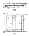
- - la figure 3 est une vue analogue à la figure 2 d'une autre variante ;
- - la figure 4 est une vue de dessus de l'objet de la figure 3.
- - Figure 1 is a vertical sectional view of a freezing apparatus according to the invention;
- - Figure 2 is a partial view on a larger scale of a variant, taken in section along a line corresponding to the line II-II of Figure 1;
- - Figure 3 is a view similar to Figure 2 of another variant;
- - Figure 4 is a top view of the object of Figure 3.
L'appareil de congélation d'embryons représenté à la figure 1 comprend une enceinte extérieure 1 munie d'une isolation thermique 2 à hautes performances, et un caisson 3 muni d'une isolation thermique 4 à performances nettement inférieures.The embryo freezing apparatus shown in FIG. 1 comprises an external enclosure 1 provided with high performance
Le caisson 3 a une forme parallélépipédique aplatie et comprend essentiellement une cuve 5 et un couvercle amovible 6 tous deux en métal de forte épaisseur, par exemple de l'ordre de plusieurs millimètres, cette épaisseur étant la même pour toutes les faces de la cuve et pour le couvercle, pour des raisons de commodité de fabrication.The
La cuve 5 comprend un fond horizontal 7 sur la face inférieure duquel est collée une résistance électrique en film 8, et des parois latérales 9A, 9B. Elle est emboîtée dans une cuvette 10 en matière isolante, par exemple en mousse de matière plastique rigide, laquelle est elle-même emboîtée dans une cuvette 11 en tôle. Cette dernière est fixée à la branche horizontale inférieure 12 de deux supports 13 en L, la branche verticale 14 de ces supports traversant à coulissement deux orifices prévus dans le couvercle amovible 15 de l'enceinte 1.The tank 5 comprises a horizontal bottom 7 on the underside of which an
Des moyens non représentés permettent de positionner les supports 13 à plusieurs hauteurs, de façon à pouvoir disposer le caisson 3 dans au moins trois positions différentes dans l'enceinte 1, à savoir une position haute proche du bord supérieur des parois latérales de l'enceinte, une position intermédiaire représentée à la figure 1, et une position basse proche du fond inférieur de l'enceinte.Means not shown make it possible to position the
Par ailleurs, l'isolation 4 du caisson est complétée par une plaque 16 en matière isolante fixée sur la face externe du couvercle 6.Furthermore, the
Parallèlement à deux faces latérales 9A du caisson, il est prévu dans celui-ci deux porte-paillettes horizontaux 17. Chaque porte-paillette est constitué d'une réglette en matière isolante, par exemple en matière plastique, posée sur le fond 7 et fixée par ses extrémités aux deux autres faces latérales 9B du caisson. Ces réglettes comportent dans leur face supérieure une série d'évidements tranversaux semi-circulaires 18, alignés coaxialement deux à deux. Ainsi, une série de paillettes 19, constituées de longs tubes de faible diamètre en matière plastique, peuvent être disposées parallèlement les unes aux autres, en une seule couche horizontale, chacune des paillettes étant portée par un évidement 18 d'un porte-paillette 17 et par l'évidement associé de l'autre porte-paillettes. La hauteur du caisson n'est que légèrement supérieure à celle des porte-paillettes munis des paillettes 19.Parallel to two
En fonctionnement, on remplit partiellement l'enceinte 1 d'azote liquide, de façon à constituer un bain 20 de ce corps jusqu'à une hauteur prédéterminée ; on dispose dans chaque paillette, à une distance donnée de ses extrémités, un embryon à congeler, on charge les paillettes dans le caisson, et l'on dispose le caisson 3 ainsi chargé et muni de son couvercle dans sa position intermédiaire, ou il baigne entièrement dans les vapeurs froides d'azote qui surmontent le bain 20. Les paillettes se trouvent alors dans un même plan horizontal, et tous les embryons sont sensiblement alignés le long d'une même droite horizontale.In operation, the enclosure 1 is partially filled with liquid nitrogen, so as to constitute a
Soit par les entrées de chaleur naturelles, soit au moyen d'une résistance électrique 21 prévue près du fond de l'enceinte 1, on assure dans celle-ci une évaporation constante d'azote, par exemple de l'ordre de 1 l/h, de façon à créer autour du caisson un apport constant de frigories servant à la congélation des paillettes.Either by natural heat inputs, or by means of an
L'isolation 4 du caisson est choisie de manière telle que la vitesse de descente en température à l'intérieur de celui-ci provoquée par cet apport de frigories soit légèrement supérieure à la plus grande vitesse requise dans le programme de congélation considéré, soit quelques degrés C/mn.The
Pour ajuster la vitesse descente en température à la valeur prescrite, on apporte en outre au caisson un flux de chaleur par effet Joule commandé de façon précise au moyen de la résistance 8, par l'intermédiaire de fils (non représentés) s'étendant dans les supports 13 jusqu'à une source de courant électrique (non représentée) extérieure à l'enceinte 1. Cet apport de chaleur est homogénéisé ou diffusé sur toute la surface du fond 7 du caisson par la forte épaisseur de ce fond, et il est commandé par un régulateur (non représenté) à partir des données de température fournies par un thermo-couple (non représenté) dont est équipée l'une des paillettes.To adjust the rate of temperature decrease to the prescribed value, a Joule effect heat flow is also brought to the box precisely controlled by means of the
Ainsi, les paillettes sont confinées dans un espace restreint presque isotherme mais dans lequel se produit tout de même une certaine convection naturelle de bas en haut, et les paillettes ne sont soumises, de point de vue thermique, qu'à cette seule convection naturelle.Thus, the flakes are confined in a restricted space which is almost isothermal but in which a certain natural convection still occurs from the bottom up, and the flakes are subjected, from a thermal point of view, to this single natural convection.
Grâce à la manière dont sont assurés les apports de froid et de chaleur, les surfaces isothermes sont pratiquement horizontales dans tout le caisson, et en particulier, compte tenu de la disposition des paillettes en une seule couche horizontale, toutes les paillettes sont à chaque instant à une température uniforme. Ceci rend possible l'obtention précise du programme de température prescrit pour toutes les paillettes simultanément, la température des paillettes étant régulée à chaque instant par la régulation de la puissance dissipée dans la résistance 8, à partir des données correspondant à une seule des paillettes.Thanks to the way in which the contributions of cold and heat are ensured, the isothermal surfaces are practically horizontal in all the box, and in particular, taking into account the arrangement of the flakes in a single horizontal layer, all the flakes are at all times at a uniform temperature. This makes it possible to obtain the precise temperature program prescribed for all the flakes simultaneously, the temperature of the flakes being regulated at all times by regulating the power dissipated in the
Lorsqu'une température de surfusion choisie (par exemple - 7°C) est atteinte, on remonte le caisson jusqu'à sa position supérieure, et l'on ouvre le couvercle 15 de l'enceinte. Le caisson se trouve alors dans un environnement constitué d'un mélange d'azote froid et d'air ambiant, à une température voisine de cette température de surfusion. On ouvre ensuite le couvercle 6 du caisson, et l'on procède au seeding en amenant au contact de toutes les paillettes, à l'emplacement des embryons, une barre métallique horizontale, dite "inducteur thermique", préalablement refroidie dans de l'azote liquide.When a chosen supercooling temperature (for example - 7 ° C) is reached, the casing is raised to its upper position, and the
Ensuite, on referme le caisson puis l'enceinte 1, on redescend le caisson à sa position intermédiaire, et l'on poursuit le programme de descente en température comme précédemment jusqu'à une température déterminée de congélation (par exemple -35°C).Then, the box is closed again then the enclosure 1, the box is lowered to its intermediate position, and the temperature reduction program is continued as before until a determined freezing temperature (for example -35 ° C) .
Enfin, on descend le caisson jusqu'à sa position basse pour l'immerger dans le bain 20 d'azote liquide et assurer la phase finale de la congélation des embryons, ayant leur transfert dans un récipient de stockage cryobiologique.Finally, the box is lowered to its low position to immerse it in the
L'appareil ainsi décrit est économique, robuste et fiable grâce à l'absence totale de pièces en mouvement telles que moteur, ventilateur, électrovannes ou organes d'agitation.The device thus described is economical, robust and reliable thanks to the total absence of moving parts such as motor, fan, solenoid valves or agitating members.
La figure 2 illustre une variante qui permet d'améliorer encore l'homogénéité des descentes en température des différentes paillettes en assurant positivement la présence d'un isotherme horizontal à leur niveau, au moins à l'emplacement des embryons. Pour celà, on dispose horizontalement, juste au-dessus et juste au-dessous de la couche des paillettes, deux plaques métalliques de faible épaisseur, par exemple de 5/20 à 1 mm d'épaisseur, qui ne sont pas en contact thermique avec le caisson 3. Dans l'exemple de la figure 2, la plaque inférieure 22, légèrement bombée vers le haut, est fixée par deux côtés opposés aux deux porte-paillettes 17, dont l'un porte une cornière 23 servant à positionner longitudinalement une extrémité des paillettes. A mi-distance entre les porte-paillettes, ce qui correspond à l'emplacement des embryons, cette plaque 22 se trouve au niveau de la génératrice inférieure des évidements 18 et donc des paillettes 19.FIG. 2 illustrates a variant which makes it possible to further improve the homogeneity of the temperature drops of the different flakes by positively ensuring the presence of a horizontal isotherm at their level, at least at the location of the embryos. For this, we have horizontally, just above and just below the glitter layer, two thin metal plates, for example 5/20 to 1 mm thick, which are not in thermal contact with the
La plaque supérieure 24 a une dimension, dans le sens longitudinal des paillettes, légèrement inférieure à la distance séparant les deux porte-paillettes. Elle est plane et horizontale et est fixée à la face inférieure d'une plaque de mousse souple parallélépipédique 25 elle-même fixée à la face inférieure de couvercle 6 du caisson et thermiquement isolante.The
Lorsque l'on charge le caisson avec les paillettes, la zone de celles-ci contenant les embryons vient au contact de la plaque inférieure 22 puis, lorsque l'on referme le couvercle 6, la plaque supérieure 24 vient s'appuyer légèrement, avec une force limitée par l'élasticité de la plaque de mousse 25, contre les paillettes. Pendant la descente en température, les plaques 22 et 24, étant conductrices thermiquement, définissent chacune une surface isotherme, ce qui assure une très grande homogénéité de température des embryons. Ceci resterait d'ailleurs vrai si les plaques n'étaient pas au contact des paillettes mais, grâce à ce contact, ces plaques procurent, de par leur inertie thermique, une meilleure régulation de la seconde descente en température après le seeding.When the casing is loaded with the flakes, the area of these containing the embryos comes into contact with the
Dans la variante des figures 3 et 4, la plaque 22 est plane, et la plaque 24 est simplement posée sur les paillettes. De plus, la plaque 24 présente une fenêtre transversale 26 qui laisse apparaître toutes les paillettes au droit de l'emplacement des embryons, ce qui permet d'effectuer le seeding sans retirer cette plaque.In the variant of Figures 3 and 4, the
En variante encore, la face supérieure de couvercle 6 du caisson peut être elle aussi pourvue de moyens de chauffage tels qu'une résistance en film collée, l'apport de chaleur étant alors réalisé sur les deux grandes faces du caisson. Cette seconde résistance est particulièrement souhaitable dans une variante de l'appareil (non représentée) dans laquelle le couvercle 6 est dépourvu de toute isolation thermique.In another variant, the upper face of the
Claims (11)
Priority Applications (1)
| Application Number | Priority Date | Filing Date | Title |
|---|---|---|---|
| AT87401726T ATE63669T1 (en) | 1986-07-28 | 1987-07-24 | FREEZER BY CRYING LIQUID FOR BIOLOGICAL PRODUCTS PACKED IN STRAWS. |
Applications Claiming Priority (2)
| Application Number | Priority Date | Filing Date | Title |
|---|---|---|---|
| FR8610908A FR2602858B1 (en) | 1986-07-28 | 1986-07-28 | APPARATUS FOR FREEZING ORGANIC PRODUCTS PACKED IN FLAKES USING A CRYOGENIC LIQUID |
| FR8610908 | 1986-07-28 |
Publications (2)
| Publication Number | Publication Date |
|---|---|
| EP0258092A1 true EP0258092A1 (en) | 1988-03-02 |
| EP0258092B1 EP0258092B1 (en) | 1991-05-22 |
Family
ID=9337795
Family Applications (1)
| Application Number | Title | Priority Date | Filing Date |
|---|---|---|---|
| EP87401726A Expired - Lifetime EP0258092B1 (en) | 1986-07-28 | 1987-07-24 | Freezing apparatus for biological products packaged in straw, using a cryogenic liquid |
Country Status (8)
| Country | Link |
|---|---|
| US (1) | US4783973A (en) |
| EP (1) | EP0258092B1 (en) |
| AT (1) | ATE63669T1 (en) |
| AU (1) | AU593928B2 (en) |
| CA (1) | CA1303372C (en) |
| DE (1) | DE3770217D1 (en) |
| ES (1) | ES2022401B3 (en) |
| FR (1) | FR2602858B1 (en) |
Families Citing this family (11)
| Publication number | Priority date | Publication date | Assignee | Title |
|---|---|---|---|---|
| FR2651793B1 (en) * | 1989-09-14 | 1991-12-06 | Cassou Robert | TUBES OR SEQUINS FOR THE CRYOGENIC PRESERVATION OF BIOLOGICAL SAMPLES SUCH AS VIRUSES, AND FILLING METHOD. |
| US5469711A (en) * | 1994-04-15 | 1995-11-28 | Infrared Components Corporation | Cryogenic packaging for uniform cooling |
| US5595866A (en) * | 1994-05-27 | 1997-01-21 | Methodist Hospital Of Indiana, Inc. | Step-wise method to remove cryoprotectant from sperm |
| AU2216301A (en) * | 2000-01-04 | 2001-07-16 | Thermokeep Ltd. | Temperature controlling apparatus and method |
| DE10251722A1 (en) * | 2002-11-06 | 2004-05-27 | Fraunhofer-Gesellschaft zur Förderung der angewandten Forschung e.V. | Carrier for sample holders, to preserve biological samples at very low temperatures, comprises a two-piece frame with profiled facing surfaces to form holders and a release lock |
| DE10251669B3 (en) * | 2002-11-06 | 2004-06-17 | Fraunhofer-Gesellschaft zur Förderung der angewandten Forschung e.V. | Capillary substrate for low temperature storage of suspension samples |
| DE10328869A1 (en) * | 2003-06-26 | 2005-01-20 | Fraunhofer-Gesellschaft zur Förderung der angewandten Forschung e.V. | Sample receiving device and method for its production |
| DE102004047965B4 (en) * | 2004-10-01 | 2007-03-01 | Fraunhofer-Gesellschaft zur Förderung der angewandten Forschung e.V. | Cryo device and associated operating method |
| US20130263608A1 (en) * | 2010-09-14 | 2013-10-10 | Quantum Production Limited | Cryogenic storage devices |
| JP6252913B2 (en) * | 2015-05-20 | 2017-12-27 | パナソニックIpマネジメント株式会社 | Constant temperature transport method |
| US11352262B2 (en) | 2017-12-18 | 2022-06-07 | Praxair Technology, Inc. | Methods for automatic filling, charging and dispensing carbon dioxide snow block |
Citations (11)
| Publication number | Priority date | Publication date | Assignee | Title |
|---|---|---|---|---|
| FR1296171A (en) * | 1961-07-18 | 1962-06-15 | Union Carbide Corp | Method and apparatus for thermal treatment of biological substances |
| DE1401608A1 (en) * | 1962-08-23 | 1968-10-17 | Siemens Elektrogeraete Gmbh | Container for storing frozen chilled goods |
| FR1566664A (en) * | 1968-03-26 | 1969-05-09 | ||
| US4232453A (en) * | 1978-09-25 | 1980-11-11 | C. Reichert Optische Werke, Ag | Device for freeze drying and synthetic resin impregnation when necessary of small biological objects for electron microscopic examination |
| FR2468908A1 (en) * | 1979-11-03 | 1981-05-08 | Reichert Optische Werke Ag | DEVICE FOR CRYO-SUBSTITUTION OF SMALL BIOLOGICAL SAMPLES FOR THE PURPOSES OF MICROSCOPIC STUDY, PARTICULARLY IN ELECTRON MICROSCOPY |
| DE3125345A1 (en) * | 1981-06-27 | 1983-01-20 | Franz Dr.-Ing. 8552 Höchstadt Dittrich | Method for automatic freezing of a material, in particular a biological material |
| EP0090599A1 (en) * | 1982-03-26 | 1983-10-05 | Dean W. Schilling | Cryogenic device and method |
| DE3225672A1 (en) * | 1982-07-09 | 1984-01-12 | Messer Griesheim Gmbh, 6000 Frankfurt | Apparatus for initiating crystal formation in biological samples to be frozen |
| EP0150146A2 (en) * | 1984-01-19 | 1985-07-31 | L'air Liquide, Societe Anonyme Pour L'etude Et L'exploitation Des Procedes Georges Claude | Apparatus for freezing biological products packaged in straw |
| EP0181235A2 (en) * | 1984-11-09 | 1986-05-14 | Cryologic Pty. Ltd. | Cryosystem for biological material |
| EP0184417A2 (en) * | 1984-11-30 | 1986-06-11 | Board Of Regents, The University Of Texas System | Apparatus and method for cryopreparing biological tissue for ultrastructural analysis |
Family Cites Families (10)
| Publication number | Priority date | Publication date | Assignee | Title |
|---|---|---|---|---|
| US3024076A (en) * | 1957-09-25 | 1962-03-06 | Philips Corp | Packing for ampullas or similar container |
| US3080725A (en) * | 1960-08-11 | 1963-03-12 | Union Carbide Corp | Method and apparatus for controlled rate cooling and warming of biological substances |
| US3151760A (en) * | 1960-12-27 | 1964-10-06 | Union Carbide Corp | Container for the low temperature preservation of biological substances |
| US4091632A (en) * | 1976-01-27 | 1978-05-30 | Marchewka Richard B | Beverage cooling device having consumable foodstuff therein |
| US4304293A (en) * | 1979-06-18 | 1981-12-08 | Helmholtz-Institut Fur Biomedizinische Technik | Process and apparatus for freezing living cells |
| US4455842A (en) * | 1981-07-15 | 1984-06-26 | Biotech Research Laboratories, Inc. | Device and method for controlled freezing of cell cultures |
| US4429542A (en) * | 1981-08-10 | 1984-02-07 | Hoxan Corporation | Method of freezing fertilized ova, spermatozoa or the like and apparatus therefor |
| US4537034A (en) * | 1982-07-29 | 1985-08-27 | Crouch Michael D | Method for controlled reduction in temperature and preservation of embryos in a cryogenic state |
| AU577636B2 (en) * | 1984-11-09 | 1988-09-29 | Cryologic Pty Ltd | Cryostem for biological material |
| AU6472786A (en) * | 1985-09-26 | 1987-04-24 | Yianni Attikiouzel | Specimen cooling and warming apparatus and method |
-
1986
- 1986-07-28 FR FR8610908A patent/FR2602858B1/en not_active Expired
-
1987
- 1987-07-22 US US07/077,671 patent/US4783973A/en not_active Expired - Lifetime
- 1987-07-24 DE DE8787401726T patent/DE3770217D1/en not_active Expired - Lifetime
- 1987-07-24 AT AT87401726T patent/ATE63669T1/en not_active IP Right Cessation
- 1987-07-24 EP EP87401726A patent/EP0258092B1/en not_active Expired - Lifetime
- 1987-07-24 ES ES87401726T patent/ES2022401B3/en not_active Expired - Lifetime
- 1987-07-27 CA CA000543073A patent/CA1303372C/en not_active Expired - Lifetime
- 1987-07-27 AU AU76132/87A patent/AU593928B2/en not_active Ceased
Patent Citations (11)
| Publication number | Priority date | Publication date | Assignee | Title |
|---|---|---|---|---|
| FR1296171A (en) * | 1961-07-18 | 1962-06-15 | Union Carbide Corp | Method and apparatus for thermal treatment of biological substances |
| DE1401608A1 (en) * | 1962-08-23 | 1968-10-17 | Siemens Elektrogeraete Gmbh | Container for storing frozen chilled goods |
| FR1566664A (en) * | 1968-03-26 | 1969-05-09 | ||
| US4232453A (en) * | 1978-09-25 | 1980-11-11 | C. Reichert Optische Werke, Ag | Device for freeze drying and synthetic resin impregnation when necessary of small biological objects for electron microscopic examination |
| FR2468908A1 (en) * | 1979-11-03 | 1981-05-08 | Reichert Optische Werke Ag | DEVICE FOR CRYO-SUBSTITUTION OF SMALL BIOLOGICAL SAMPLES FOR THE PURPOSES OF MICROSCOPIC STUDY, PARTICULARLY IN ELECTRON MICROSCOPY |
| DE3125345A1 (en) * | 1981-06-27 | 1983-01-20 | Franz Dr.-Ing. 8552 Höchstadt Dittrich | Method for automatic freezing of a material, in particular a biological material |
| EP0090599A1 (en) * | 1982-03-26 | 1983-10-05 | Dean W. Schilling | Cryogenic device and method |
| DE3225672A1 (en) * | 1982-07-09 | 1984-01-12 | Messer Griesheim Gmbh, 6000 Frankfurt | Apparatus for initiating crystal formation in biological samples to be frozen |
| EP0150146A2 (en) * | 1984-01-19 | 1985-07-31 | L'air Liquide, Societe Anonyme Pour L'etude Et L'exploitation Des Procedes Georges Claude | Apparatus for freezing biological products packaged in straw |
| EP0181235A2 (en) * | 1984-11-09 | 1986-05-14 | Cryologic Pty. Ltd. | Cryosystem for biological material |
| EP0184417A2 (en) * | 1984-11-30 | 1986-06-11 | Board Of Regents, The University Of Texas System | Apparatus and method for cryopreparing biological tissue for ultrastructural analysis |
Also Published As
| Publication number | Publication date |
|---|---|
| AU593928B2 (en) | 1990-02-22 |
| DE3770217D1 (en) | 1991-06-27 |
| FR2602858A1 (en) | 1988-02-19 |
| EP0258092B1 (en) | 1991-05-22 |
| AU7613287A (en) | 1988-02-04 |
| US4783973A (en) | 1988-11-15 |
| CA1303372C (en) | 1992-06-16 |
| ES2022401B3 (en) | 1991-12-01 |
| FR2602858B1 (en) | 1988-11-10 |
| ATE63669T1 (en) | 1991-06-15 |
Similar Documents
| Publication | Publication Date | Title |
|---|---|---|
| EP0258092B1 (en) | Freezing apparatus for biological products packaged in straw, using a cryogenic liquid | |
| CA2038874A1 (en) | Fast freezing (heating) facility of in-case containers such as bottles | |
| CA1298713C (en) | Freezing device for plaky biological products | |
| FR2530004A1 (en) | DEVICE FOR FREEZING BIOLOGICAL PRODUCTS PACKED IN TUBES, BULBS OR FLAKES | |
| JP2000242162A (en) | Natural phenomena observation device by temperature change of water | |
| EP2536291B1 (en) | Home yogurt maker and method for the quick preparation of yogurt | |
| FR2491607A1 (en) | METHOD AND DEVICE FOR STORING LOW TEMPERATURE THERMAL ENERGY AND THEIR APPLICATION | |
| FR2563617A1 (en) | Process and device for keeping a bottle of wine at a predetermined temperature | |
| FR2643797A1 (en) | CONVECTION HEATED WAX HEAVY CLEANING APPARATUS | |
| FR2613219A1 (en) | ACCUMULATOR HEATER | |
| FR2952796A1 (en) | Electric household appliance i.e. refrigerator, for preserving and serving cheese, has cold part that is in contact with air or with each element placed in free space, where part comprises constant positive temperature during operation | |
| BE486972A (en) | ||
| EP2407031B1 (en) | Device for hollow shell moulding by thermal setting | |
| FR2599344A1 (en) | Device for the hygrometric regulation of an enclosure | |
| JPS6259583B2 (en) | ||
| JPH02200601A (en) | Freezer of zygote, sperm or the like | |
| FR2752456A1 (en) | Thermally regulated transfer arrangement for refrigerated products from vat to storage chamber | |
| FR2835045A1 (en) | Cold store for fresh produce has loading opening defining chamber with side and top access openings | |
| FR3094780A1 (en) | Food storage device | |
| FR2468861A1 (en) | MOBILE ROOFING PARTITIONING DEVICE FOR REFRIGERATOR | |
| FR2720502A1 (en) | Indicator for monitoring the refrigeration and freezing temperature of food. | |
| FR2582397A1 (en) | Device for integrated measurement with respect to time of the exceeding of a temperature and application to monitoring the heating of a premises | |
| CH628435A5 (en) | Cryoviscosimeter | |
| FR2572502A1 (en) | Tray for the cold manipulation of various products | |
| WO2011098741A1 (en) | Machine for sealing tubes made of a weldable plastic material |
Legal Events
| Date | Code | Title | Description |
|---|---|---|---|
| PUAI | Public reference made under article 153(3) epc to a published international application that has entered the european phase |
Free format text: ORIGINAL CODE: 0009012 |
|
| 17P | Request for examination filed |
Effective date: 19870729 |
|
| AK | Designated contracting states |
Kind code of ref document: A1 Designated state(s): AT BE CH DE ES FR GB GR IT LI LU NL SE |
|
| 17Q | First examination report despatched |
Effective date: 19890904 |
|
| GRAA | (expected) grant |
Free format text: ORIGINAL CODE: 0009210 |
|
| AK | Designated contracting states |
Kind code of ref document: B1 Designated state(s): AT BE CH DE ES FR GB GR IT LI LU NL SE |
|
| ITF | It: translation for a ep patent filed |
Owner name: BARZANO' E ZANARDO MILANO S.P.A. |
|
| PG25 | Lapsed in a contracting state [announced via postgrant information from national office to epo] |
Ref country code: NL Effective date: 19910522 Ref country code: GR Free format text: LAPSE BECAUSE OF FAILURE TO SUBMIT A TRANSLATION OF THE DESCRIPTION OR TO PAY THE FEE WITHIN THE PRESCRIBED TIME-LIMIT Effective date: 19910522 |
|
| REF | Corresponds to: |
Ref document number: 63669 Country of ref document: AT Date of ref document: 19910615 Kind code of ref document: T |
|
| REF | Corresponds to: |
Ref document number: 3770217 Country of ref document: DE Date of ref document: 19910627 |
|
| PGFP | Annual fee paid to national office [announced via postgrant information from national office to epo] |
Ref country code: LU Payment date: 19910628 Year of fee payment: 5 |
|
| PGFP | Annual fee paid to national office [announced via postgrant information from national office to epo] |
Ref country code: NL Payment date: 19910731 Year of fee payment: 5 |
|
| GBT | Gb: translation of ep patent filed (gb section 77(6)(a)/1977) | ||
| NLV1 | Nl: lapsed or annulled due to failure to fulfill the requirements of art. 29p and 29m of the patents act | ||
| EPTA | Lu: last paid annual fee | ||
| PLBE | No opposition filed within time limit |
Free format text: ORIGINAL CODE: 0009261 |
|
| STAA | Information on the status of an ep patent application or granted ep patent |
Free format text: STATUS: NO OPPOSITION FILED WITHIN TIME LIMIT |
|
| 26N | No opposition filed | ||
| PG25 | Lapsed in a contracting state [announced via postgrant information from national office to epo] |
Ref country code: LU Free format text: LAPSE BECAUSE OF NON-PAYMENT OF DUE FEES Effective date: 19920724 |
|
| REG | Reference to a national code |
Ref country code: FR Ref legal event code: TP |
|
| EAL | Se: european patent in force in sweden |
Ref document number: 87401726.2 |
|
| PGFP | Annual fee paid to national office [announced via postgrant information from national office to epo] |
Ref country code: AT Payment date: 20010608 Year of fee payment: 15 |
|
| PGFP | Annual fee paid to national office [announced via postgrant information from national office to epo] |
Ref country code: FR Payment date: 20010611 Year of fee payment: 15 |
|
| PGFP | Annual fee paid to national office [announced via postgrant information from national office to epo] |
Ref country code: GB Payment date: 20010615 Year of fee payment: 15 |
|
| PGFP | Annual fee paid to national office [announced via postgrant information from national office to epo] |
Ref country code: SE Payment date: 20010618 Year of fee payment: 15 Ref country code: CH Payment date: 20010618 Year of fee payment: 15 |
|
| PGFP | Annual fee paid to national office [announced via postgrant information from national office to epo] |
Ref country code: DE Payment date: 20010625 Year of fee payment: 15 |
|
| PGFP | Annual fee paid to national office [announced via postgrant information from national office to epo] |
Ref country code: ES Payment date: 20010709 Year of fee payment: 15 |
|
| PGFP | Annual fee paid to national office [announced via postgrant information from national office to epo] |
Ref country code: BE Payment date: 20010713 Year of fee payment: 15 |
|
| REG | Reference to a national code |
Ref country code: GB Ref legal event code: IF02 |
|
| PG25 | Lapsed in a contracting state [announced via postgrant information from national office to epo] |
Ref country code: GB Free format text: LAPSE BECAUSE OF NON-PAYMENT OF DUE FEES Effective date: 20020724 Ref country code: AT Free format text: LAPSE BECAUSE OF NON-PAYMENT OF DUE FEES Effective date: 20020724 |
|
| PG25 | Lapsed in a contracting state [announced via postgrant information from national office to epo] |
Ref country code: SE Free format text: LAPSE BECAUSE OF NON-PAYMENT OF DUE FEES Effective date: 20020725 Ref country code: ES Free format text: LAPSE BECAUSE OF NON-PAYMENT OF DUE FEES Effective date: 20020725 |
|
| PG25 | Lapsed in a contracting state [announced via postgrant information from national office to epo] |
Ref country code: LI Free format text: LAPSE BECAUSE OF NON-PAYMENT OF DUE FEES Effective date: 20020731 Ref country code: CH Free format text: LAPSE BECAUSE OF NON-PAYMENT OF DUE FEES Effective date: 20020731 Ref country code: BE Free format text: LAPSE BECAUSE OF NON-PAYMENT OF DUE FEES Effective date: 20020731 |
|
| BERE | Be: lapsed |
Owner name: S.A. L'*AIR LIQUIDE POUR L'ETUDE ET L'EXPLOITATION Effective date: 20020731 |
|
| PG25 | Lapsed in a contracting state [announced via postgrant information from national office to epo] |
Ref country code: DE Free format text: LAPSE BECAUSE OF NON-PAYMENT OF DUE FEES Effective date: 20030201 |
|
| EUG | Se: european patent has lapsed | ||
| REG | Reference to a national code |
Ref country code: CH Ref legal event code: PL |
|
| GBPC | Gb: european patent ceased through non-payment of renewal fee |
Effective date: 20020724 |
|
| PG25 | Lapsed in a contracting state [announced via postgrant information from national office to epo] |
Ref country code: FR Free format text: LAPSE BECAUSE OF NON-PAYMENT OF DUE FEES Effective date: 20030331 |
|
| REG | Reference to a national code |
Ref country code: FR Ref legal event code: ST |
|
| REG | Reference to a national code |
Ref country code: ES Ref legal event code: FD2A Effective date: 20030811 |
|
| PG25 | Lapsed in a contracting state [announced via postgrant information from national office to epo] |
Ref country code: IT Free format text: LAPSE BECAUSE OF NON-PAYMENT OF DUE FEES;WARNING: LAPSES OF ITALIAN PATENTS WITH EFFECTIVE DATE BEFORE 2007 MAY HAVE OCCURRED AT ANY TIME BEFORE 2007. THE CORRECT EFFECTIVE DATE MAY BE DIFFERENT FROM THE ONE RECORDED. Effective date: 20050724 |