EP0257978A2 - Security closure and carrying handle for a container - Google Patents
Security closure and carrying handle for a container Download PDFInfo
- Publication number
- EP0257978A2 EP0257978A2 EP87307345A EP87307345A EP0257978A2 EP 0257978 A2 EP0257978 A2 EP 0257978A2 EP 87307345 A EP87307345 A EP 87307345A EP 87307345 A EP87307345 A EP 87307345A EP 0257978 A2 EP0257978 A2 EP 0257978A2
- Authority
- EP
- European Patent Office
- Prior art keywords
- closure
- container
- projections
- panel
- mouth
- Prior art date
- Legal status (The legal status is an assumption and is not a legal conclusion. Google has not performed a legal analysis and makes no representation as to the accuracy of the status listed.)
- Granted
Links
Images


Classifications
-
- B—PERFORMING OPERATIONS; TRANSPORTING
- B65—CONVEYING; PACKING; STORING; HANDLING THIN OR FILAMENTARY MATERIAL
- B65D—CONTAINERS FOR STORAGE OR TRANSPORT OF ARTICLES OR MATERIALS, e.g. BAGS, BARRELS, BOTTLES, BOXES, CANS, CARTONS, CRATES, DRUMS, JARS, TANKS, HOPPERS, FORWARDING CONTAINERS; ACCESSORIES, CLOSURES, OR FITTINGS THEREFOR; PACKAGING ELEMENTS; PACKAGES
- B65D33/00—Details of, or accessories for, sacks or bags
- B65D33/16—End- or aperture-closing arrangements or devices
- B65D33/34—End- or aperture-closing arrangements or devices with special means for indicating unauthorised opening
-
- B—PERFORMING OPERATIONS; TRANSPORTING
- B65—CONVEYING; PACKING; STORING; HANDLING THIN OR FILAMENTARY MATERIAL
- B65D—CONTAINERS FOR STORAGE OR TRANSPORT OF ARTICLES OR MATERIALS, e.g. BAGS, BARRELS, BOTTLES, BOXES, CANS, CARTONS, CRATES, DRUMS, JARS, TANKS, HOPPERS, FORWARDING CONTAINERS; ACCESSORIES, CLOSURES, OR FITTINGS THEREFOR; PACKAGING ELEMENTS; PACKAGES
- B65D33/00—Details of, or accessories for, sacks or bags
- B65D33/16—End- or aperture-closing arrangements or devices
- B65D33/1683—A pair of interconnecting rigid strips made of plastic material, e.g. one or both being provided with a handle or suspension means
-
- B—PERFORMING OPERATIONS; TRANSPORTING
- B65—CONVEYING; PACKING; STORING; HANDLING THIN OR FILAMENTARY MATERIAL
- B65D—CONTAINERS FOR STORAGE OR TRANSPORT OF ARTICLES OR MATERIALS, e.g. BAGS, BARRELS, BOTTLES, BOXES, CANS, CARTONS, CRATES, DRUMS, JARS, TANKS, HOPPERS, FORWARDING CONTAINERS; ACCESSORIES, CLOSURES, OR FITTINGS THEREFOR; PACKAGING ELEMENTS; PACKAGES
- B65D5/00—Rigid or semi-rigid containers of polygonal cross-section, e.g. boxes, cartons or trays, formed by folding or erecting one or more blanks made of paper
- B65D5/42—Details of containers or of foldable or erectable container blanks
- B65D5/44—Integral, inserted or attached portions forming internal or external fittings
- B65D5/46—Handles
Definitions
- This invention relates to a security closure for a bag, case or other container and which cannot be opened without obvious evidence that it has been opened.
- the closure is particularly suitable for use with a bag for transporting bullion and coins between banks and bullion houses.
- a security closure for a carrying container comprising a first member formed with projections for passing through holes formed in the mouth of said container, and a second member for engagement with the first member and the projections thereof to close the mouth of the container and hold it closed, at least one of said members being formed with a carrying handle and one of said members being formed with an aperture portion to receive a tell-tale or security member passing through an aperture in said portion, said portion being located such that the container cannot be opened from the closed position either without destroying said tell-tale or due to the presence of the security member.
- the closure comprises two panel members adapted to be fitted or clamped together about the mouth of the container.
- the first panel member is formed with a plurality of first projections and the second panel member is formed with a plurality of first apertures each intended to receive a respective first projection as an interference, force or snap fit.
- An apertured second projection constituting said apertured portion is formed on one panel member and the other is formed with an aperture to receive such projection.
- a tell-tale or security member e.g. a padlock
- the tell-tale is of such a size or shape that any attempt to disengage the panel members will detroy the tell-tale.
- the securing member cnan be such as to prevent disengagement of the panel members.
- the two panel members may be separate but are preferably hinged together and are intended to be closed about the mouth of a carrying bag formed with apertures through which the projections on the first panel pass.
- the carrying handle is conveniently formed by an aperture of appropriate size in each panel member.
- the panels may be attached to opposite sides of the mouth of a carrying case.
- one of the members is in the form of a panel member and the other is inn the form of a rod or the like.
- the panel member is formed with a series of projections each formed with an aperture aligned with the apertures in the other projections so that the rod or the like can be passed through the apertures to hold the mouth of the container between the rod and the panel.
- the rod is formed at one end with an enlarged portion which will not pass through the apertures in the projections and at the other end with an aperture to receive the tell-tale or security member.
- the combination of the security closure indicated above and a container which may be in the form of a bag the mouth of which is formed with holes to receive the projections, or which may be in the form of a carrying case of rigid or substantially rigid material in which case the closure is in the form of two panels members integral with the closing edges of the mouth of the case.
- the panels may be made of plastics, and polypropylene has the required properties of resilience and toughness to provide a reusable closure. However, if desired a more frangible material could be used to provide evidence of tampering.
- a security closure which comprises a first rectangular panel member 1 and a second rectangular panel member 2.
- the first panel member 1 is formed with six projections 3 which are substantially mushroom shaped (c.f. Figure 3). The projections are spaced apart equally along the bottom longer edge of the panel on each side of a central parallelopiped shaped projection 4 which is formed with a through slot 5.
- the panel member 1 is formed with a large aperture 6 which constitutes a handhold.
- the second panel member 2 is formed with six circular apertures 7 each of which is intended to receive a respective one of the mushroom shaped projections 3 and a rectangular aperture 8 to receive the projection 4 on the first panel member.
- the panel member 2 is also formed with a large aperture 9 to register with the aperture 6.
- the shorter edges of the second panel member are turned in at 10 to embrace the shorter edges of the first panel member 1 and provide a snap closure when the two panel members are fitted together.
- the two panel members are adapted to be fitted together around the mouth of a carrying bag 11 with the projections 3 snap fitting into the apertures 7 and the projection 4 passing through the aperture 8.
- the mouth of the bag is formed with apertues 12 through which the projections 3 pass and apertures 13 through which the projection 4 passes.
- a security member or tell tale can be passed through the slot 5 and this may take the form of a padlock or a plastics ratchet moulding that is irreversible and has to be cut to release it.
- a plastics or other strip which has a security stamping or identification symbol can be adhesively secured through the slot.
- Figures 2 and 3 show a modification of the closure shown in Figure 1 and like parts have the same reference numerals.
- the two panel members 1 and 2 are hingedly connected along their longer edges opposite the projections and apertures by a hinge 14 which may be continuous or interrupted and is conveniently formed of the same material as the panel members and integral therewith.
- Figure 2 also shows a security tell tale 15 in the slot 5.
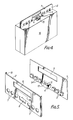
- Figure 4 shows a further modification in which the panel members 1 and 2 are made integral with closing edges of the mouth of a carrying case 16 of rigid material.
- this modification it may be desirable to increase the numbers of projections 3 and respective apertures 7 in the panels or possibly to provide more than one projection 4 and respective slot 8 in order adequately to prevent tampering.
- Any unuathorised attempt to open the carrying container is either prevented by the security member, e.g. a padlock, or results in destruction or defacing of the tell tale.
- the security member e.g. a padlock
- FIG 5 shows a further modification of the security closure shown in Figure 1 and again like parts have the same reference numerals.
- the projection 4 is formed with a raised portion 17 at its front end, similar to a rifle foresight and the aperture 8 is formed with an extension 18 to receive the portion 17.
- a security label is applied to the area 19 on the panel 2 so that any withdrawal of the projection 4 through the aperture 8 will cause the raised portion 17 to clip the label, thus providing evidence that the closure had been opened or tampered with.
- a fresh label would be applied when the closure is re-used or the label could be a specially printed removable one. It will of course be appreciated that this modification is applicable also to the security closures shown in Figures 2 and 3 and in Figure 4.
- projections 3 have been shown as mushroom shaped and of circular cross-section and as providing a snap fit in the apertures 7, they could be of any desired cross-sectioned shape and could provide an interference or force fit in apertures 7 of corresponding complementary shape.
- FIG. 6 of the drawings there is shown a simplified version of the closure.
- the panel is also formed with a series, in this case four, of projections 22, each of which, as shown in the cross-sections to the right of the Figure is either in the form of an apertured projection or in the form of a strap of the panel material pushed out of the plane of the panel, in each case the projections defining a series of aligned apertures or hoops for receiving a rod 23.
- the rod 23 has a thickened portion 24 at one end and the other end is formed with an aperture (not shown).
- a security collar 24 can be slid on to the other end of the rod 23 and is formed with an aperture 25 which can be registered with the aperture in the rod whereafter a tell-tale or security member can be passed through the registering apertures.
- the security closure shown in Figure 6 is for use with a bag 26, the mouth of which is shown in Figure 7 in an open state. From Figure 7, it can be seen that the mouth of the bag is formed on each side with an upper row of holes 27 and a lower row of holes 28. The spacing between the holes in each row is equal to the spacing of the projections 22.
- the mouth is closed so as to bring the holes 27 and 28 on each side of the bag into register.
- the top of the bag is then folded over, as shown in Figure 6, so that the holes 27 are in register with the holes 28, and the bag is presented to the panel 26 so that the projections 22 are passed through the holes.
- the rod 23 is then passed through the apertures defined by the projections 22 and secured in place by the security collar 24, whereafter the tell-tale is applied.
- the panel members 1 and 2 can be made of any suitable material but are preferably made of polypropylene as this has the necessary resilience and toughness to provide a suitable hinge and snap fitting. Furthermore, it is convenient to form the panels and integral hinge by molding them from polypropylene. However, it would be possible to make the members or at least the projections of a frangible material so that any unauthorised attempt to open the closure would cause the projections to snap off and provide evidence of tampering.
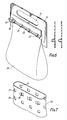
- Figure 8 shows a moulding for forming a security closure for a bag.
- the moulding comprises two panel portions 30 and 31, the panel portion 30 being formed with apertures 32 and the panel portion 31 being formed with U-shaped projections 33.
- the panel portion 31 also has an integral hand girip 34 of inverted T-section as shown in the cross-sections to the right of the Figure taken along the line VIII-VIII. On each side of the hand girip 34, the panel portions 30 and 31 are joined by straps 35 which can act as hinges.
- the moulding can also include a rod 36, shown in broken lines, which is thickened at one end 37 and formed with an aperture 38 at the other.
- the rod 36 is joined to the panel portion 30 by runners 39 during moulding. These runners can subsequently be removed so that the rod is available for locking the closure.
- the two panel portions are folded about the hinges 35, the projections 33 are passed through holes in the mouth of a bag and through the apertures 32, whereupon the rod 36 is passed through the projections and held in place by a security member and/or tell-tale.
- the bag When the present closure is used in conjunction with a bag 11 or 26, the bag is conveniently made of plastics material and is preferably transparent so that the contents can be viewed.
- the bag 11 used with the closure shown in Figures 2 and 3 preferably has a mouth that is slightly narrower than the closure so that the short edges of the panels can be snap closed around it.
- holes 12 it is desirable for holes 12 to be formed in the gusset so that the gusset can be held securely between the panels.
- the mouth of the bag is desirably reinforced in the region in which the apertures 12 and 13 or 27 and 28 are formed and this may be achieved by gauge banding during manufacture or by folding the mouth of the bag to provide double thickness in this region.
- the present closure and bag are suitable for transporting bullion and coin between banks and bullion houses.
- the present linen bags which are used have the disadvantages that they are not transparent (and banks prefer to see the contents in order to ensure valid coin without opening) and they require new string and crimped closure each time they are used and this closure is said not to be tamper proof.
Abstract
Description
- This invention relates to a security closure for a bag, case or other container and which cannot be opened without obvious evidence that it has been opened. The closure is particularly suitable for use with a bag for transporting bullion and coins between banks and bullion houses.
- According to one aspect of the present invention there is provided a security closure for a carrying container comprising a first member formed with projections for passing through holes formed in the mouth of said container, and a second member for engagement with the first member and the projections thereof to close the mouth of the container and hold it closed, at least one of said members being formed with a carrying handle and one of said members being formed with an aperture portion to receive a tell-tale or security member passing through an aperture in said portion, said portion being located such that the container cannot be opened from the closed position either without destroying said tell-tale or due to the presence of the security member.
- In one embodiment of the invention, the closure comprises two panel members adapted to be fitted or clamped together about the mouth of the container. The first panel member is formed with a plurality of first projections and the second panel member is formed with a plurality of first apertures each intended to receive a respective first projection as an interference, force or snap fit. An apertured second projection constituting said apertured portion is formed on one panel member and the other is formed with an aperture to receive such projection. When the panel members are fitted together around or at the mouth of a carrying container the projections on the first panel member are received in the apertures in the second panel member and a tell-tale or security member e.g. a padlock, is inserted in the aperture in the aperture projection. The tell-tale is of such a size or shape that any attempt to disengage the panel members will detroy the tell-tale. Alternatively, the securing member cnan be such as to prevent disengagement of the panel members.
- The two panel members may be separate but are preferably hinged together and are intended to be closed about the mouth of a carrying bag formed with apertures through which the projections on the first panel pass. The carrying handle is conveniently formed by an aperture of appropriate size in each panel member.
- In an alternative contruction the panels may be attached to opposite sides of the mouth of a carrying case.
- In yet a further construction, one of the members is in the form of a panel member and the other is inn the form of a rod or the like. The panel member is formed with a series of projections each formed with an aperture aligned with the apertures in the other projections so that the rod or the like can be passed through the apertures to hold the mouth of the container between the rod and the panel. The rod is formed at one end with an enlarged portion which will not pass through the apertures in the projections and at the other end with an aperture to receive the tell-tale or security member.
- In another aspect of the present invention there is provided the combination of the security closure indicated above and a container which may be in the form of a bag the mouth of which is formed with holes to receive the projections, or which may be in the form of a carrying case of rigid or substantially rigid material in which case the closure is in the form of two panels members integral with the closing edges of the mouth of the case.
- The panels may be made of plastics, and polypropylene has the required properties of resilience and toughness to provide a reusable closure. However, if desired a more frangible material could be used to provide evidence of tampering.
- In order to enable the invention to be more readily understood, reference will now be made to the accompanying drawings, which illustrate diagrammatically and by way of example some embodiments thereof, and in which:-
- Figure 1 is an exploded view showing a security closure for use with a carrying bag,
- Figure 2 is a perspective view of a modification of the closure shown in Figure 1 in position around the mouth of a carrying bag,
- Figure 3 is a cross-section along the line III-III in Figure 2,
- Figure 4 is a perspective view of a further modification,
- Figure 5 is a view similar to Figure 1 of yet a further modification,
- Figure 6 is a perspective view of yet another security closure in use with a carrying bag,
- Figure 7 is a perspective view of the mouth of the bag shown in Figure 6 with the mouth open, and
- Figure 8 is a plan view of a moulding which can be used as a security closure.
- Referring now to Figure 1 of the drawings, there is shown a security closure which comprises a first
rectangular panel member 1 and a secondrectangular panel member 2. Thefirst panel member 1 is formed with sixprojections 3 which are substantially mushroom shaped (c.f. Figure 3). The projections are spaced apart equally along the bottom longer edge of the panel on each side of a central parallelopiped shaped projection 4 which is formed with a throughslot 5. Thepanel member 1 is formed with alarge aperture 6 which constitutes a handhold. - The
second panel member 2 is formed with sixcircular apertures 7 each of which is intended to receive a respective one of the mushroomshaped projections 3 and arectangular aperture 8 to receive the projection 4 on the first panel member. Thepanel member 2 is also formed witha large aperture 9 to register with theaperture 6. The shorter edges of the second panel member are turned in at 10 to embrace the shorter edges of thefirst panel member 1 and provide a snap closure when the two panel members are fitted together. - The two panel members are adapted to be fitted together around the mouth of a
carrying bag 11 with theprojections 3 snap fitting into theapertures 7 and the projection 4 passing through theaperture 8. In order that the bag 112 can be held between the panel members, the mouth of the bag is formed withapertues 12 through which theprojections 3 pass and apertures 13 through which the projection 4 passes. - when the two panel members are fitted together a security member or tell tale can be passed through the
slot 5 and this may take the form of a padlock or a plastics ratchet moulding that is irreversible and has to be cut to release it. Alternatively, a plastics or other strip which has a security stamping or identification symbol can be adhesively secured through the slot. - Figures 2 and 3 show a modification of the closure shown in Figure 1 and like parts have the same reference numerals. In the modification shown in Figures 2 and 3 the two
panel members hinge 14 which may be continuous or interrupted and is conveniently formed of the same material as the panel members and integral therewith. Figure 2 also shows asecurity tell tale 15 in theslot 5. - Figure 4 shows a further modification in which the
panel members carrying case 16 of rigid material. In this modification it may be desirable to increase the numbers ofprojections 3 andrespective apertures 7 in the panels or possibly to provide more than one projection 4 andrespective slot 8 in order adequately to prevent tampering. - In the use of the closures just described, in each case the user will fill the bag or case and, if necessary, appropriately position the
bag 11 between the panel members. The two panel members are then pressed together so that theprojections 3 engage in theapertures 7, slight pressure being required to snap the closure shut. Thereafter the security member or tell tale is passed through theslot 5 and secured in position. - Any unuathorised attempt to open the carrying container is either prevented by the security member, e.g. a padlock, or results in destruction or defacing of the tell tale.
- Figure 5 shows a further modification of the security closure shown in Figure 1 and again like parts have the same reference numerals. In this modification, the projection 4 is formed with a raised
portion 17 at its front end, similar to a rifle foresight and theaperture 8 is formed with an extension 18 to receive theportion 17. When the two panel members have been fitted together a security label is applied to the area 19 on thepanel 2 so that any withdrawal of the projection 4 through theaperture 8 will cause the raisedportion 17 to clip the label, thus providing evidence that the closure had been opened or tampered with. A fresh label would be applied when the closure is re-used or the label could be a specially printed removable one. It will of course be appreciated that this modification is applicable also to the security closures shown in Figures 2 and 3 and in Figure 4. - While the
projections 3 have been shown as mushroom shaped and of circular cross-section and as providing a snap fit in theapertures 7, they could be of any desired cross-sectioned shape and could provide an interference or force fit inapertures 7 of corresponding complementary shape. - Referring now to Figure 6 of the drawings, there is shown a simplified version of the closure. In this version, there is one
panel member 20 which is formed with alarge aperture 21 constituting a handhold. The panel is also formed with a series, in this case four, ofprojections 22, each of which, as shown in the cross-sections to the right of the Figure is either in the form of an apertured projection or in the form of a strap of the panel material pushed out of the plane of the panel, in each case the projections defining a series of aligned apertures or hoops for receiving arod 23. Therod 23 has a thickenedportion 24 at one end and the other end is formed with an aperture (not shown). Asecurity collar 24 can be slid on to the other end of therod 23 and is formed with anaperture 25 which can be registered with the aperture in the rod whereafter a tell-tale or security member can be passed through the registering apertures. - The security closure shown in Figure 6 is for use with a
bag 26, the mouth of which is shown in Figure 7 in an open state. From Figure 7, it can be seen that the mouth of the bag is formed on each side with an upper row ofholes 27 and a lower row ofholes 28. The spacing between the holes in each row is equal to the spacing of theprojections 22. - Aftder the
bag 26 has been filled, the mouth is closed so as to bring theholes holes 27 are in register with theholes 28, and the bag is presented to thepanel 26 so that theprojections 22 are passed through the holes. Therod 23 is then passed through the apertures defined by theprojections 22 and secured in place by thesecurity collar 24, whereafter the tell-tale is applied. - The
panel members - Figure 8 shows a moulding for forming a security closure for a bag. The moulding comprises two
panel portions panel portion 30 being formed withapertures 32 and thepanel portion 31 being formed withU-shaped projections 33. Thepanel portion 31 also has anintegral hand girip 34 of inverted T-section as shown in the cross-sections to the right of the Figure taken along the line VIII-VIII. On each side of thehand girip 34, thepanel portions straps 35 which can act as hinges. The moulding can also include a rod 36, shown in broken lines, which is thickened at oneend 37 and formed with an aperture 38 at the other. The rod 36 is joined to thepanel portion 30 by runners 39 during moulding. These runners can subsequently be removed so that the rod is available for locking the closure. - In the use of this moulding, the two panel portions are folded about the
hinges 35, theprojections 33 are passed through holes in the mouth of a bag and through theapertures 32, whereupon the rod 36 is passed through the projections and held in place by a security member and/or tell-tale. - When the present closure is used in conjunction with a
bag bag 11 used with the closure shown in Figures 2 and 3 preferably has a mouth that is slightly narrower than the closure so that the short edges of the panels can be snap closed around it. However, if a gusseted bag is used then it is desirable forholes 12 to be formed in the gusset so that the gusset can be held securely between the panels. The mouth of the bag is desirably reinforced in the region in which theapertures - The present closure and bag are suitable for transporting bullion and coin between banks and bullion houses. The present linen bags which are used have the disadvantages that they are not transparent (and banks prefer to see the contents in order to ensure valid coin without opening) and they require new string and crimped closure each time they are used and this closure is said not to be tamper proof.
- May modifications of the present closure are possible and while the panels members have been shown and described as being rectangular or somewhat rounded, it willbe appreciated that they could be of any desired shape. It will also be appreciated that the projections and, where used, the locking rods can also have different shapes.
Claims (10)
Priority Applications (1)
| Application Number | Priority Date | Filing Date | Title |
|---|---|---|---|
| AT87307345T ATE64910T1 (en) | 1986-08-20 | 1987-08-19 | SAFETY LOCK AND HANDLE FOR CONTAINER. |
Applications Claiming Priority (2)
| Application Number | Priority Date | Filing Date | Title |
|---|---|---|---|
| GB8620215 | 1986-08-20 | ||
| GB868620215A GB8620215D0 (en) | 1986-08-20 | 1986-08-20 | Closure & handle for container |
Publications (3)
| Publication Number | Publication Date |
|---|---|
| EP0257978A2 true EP0257978A2 (en) | 1988-03-02 |
| EP0257978A3 EP0257978A3 (en) | 1989-03-22 |
| EP0257978B1 EP0257978B1 (en) | 1991-07-03 |
Family
ID=10602952
Family Applications (1)
| Application Number | Title | Priority Date | Filing Date |
|---|---|---|---|
| EP87307345A Expired - Lifetime EP0257978B1 (en) | 1986-08-20 | 1987-08-19 | Security closure and carrying handle for a container |
Country Status (5)
| Country | Link |
|---|---|
| EP (1) | EP0257978B1 (en) |
| AT (1) | ATE64910T1 (en) |
| DE (1) | DE3771149D1 (en) |
| ES (1) | ES2023906B3 (en) |
| GB (1) | GB8620215D0 (en) |
Cited By (10)
| Publication number | Priority date | Publication date | Assignee | Title |
|---|---|---|---|---|
| WO1993019992A1 (en) * | 1992-03-31 | 1993-10-14 | ELC Produtos de Segurança Indústria e Comércio Ltda. | Device for the closure of bags or the like and security seal |
| US5267643A (en) * | 1992-01-06 | 1993-12-07 | Scribner Richard C | Outdoor plastic information dispenser |
| FR2741046A1 (en) * | 1995-11-10 | 1997-05-16 | Paimpol Voiles | Closure flap for packaging bag |
| BE1012177A3 (en) * | 1998-09-23 | 2000-06-06 | Stefano Carlo Di | Transport bag fitted with an encoded and removable opening and closing security device, guaranteeing the confidentiality of the contents in respect of third parties alien to the sender and to the addressee |
| EP1702857A1 (en) * | 2005-03-16 | 2006-09-20 | Angelika Schmitt | Handle for container |
| WO2010066739A1 (en) * | 2008-12-10 | 2010-06-17 | Wincor Nixdorf International Gmbh | Device and method for closing at least one thin-walled transporting container which has at least one opening and is intended for items of value |
| US20100239190A1 (en) * | 2009-03-23 | 2010-09-23 | Mcnamara Ambrose J | Tamper-Evident System and Methods For Storing Property |
| DE102009015047A1 (en) * | 2009-03-26 | 2010-09-30 | Wincor Nixdorf International Gmbh | Device for filling a thin-walled transport container with notes of value |
| US9129463B2 (en) | 2008-12-10 | 2015-09-08 | Wincor Nixdorf International Gmbh | Method for filling at least one thin-walled transport container with at least one valuable object and device for safekeeping at least one valuable object |
| CN107521836A (en) * | 2017-05-22 | 2017-12-29 | 叶陈雷 | A kind of pressurizing window structure and the air bag using the structure |
Citations (4)
| Publication number | Priority date | Publication date | Assignee | Title |
|---|---|---|---|---|
| US4175604A (en) * | 1978-11-07 | 1979-11-27 | Bonner Cletus D | Tamper proof security mail and bank collection bag |
| FR2550426A1 (en) * | 1983-08-11 | 1985-02-15 | Sepal | Device for handling bags with tamper-proof closure, in particular for the transportation of valuables |
| GB2150531A (en) * | 1983-11-28 | 1985-07-03 | Itw De France | Devices for use in closing bags |
| DE8531271U1 (en) * | 1985-11-06 | 1985-12-19 | Zykowski, Hans Peter, 5880 Lüdenscheid | Closure for sales packages |
-
1986
- 1986-08-20 GB GB868620215A patent/GB8620215D0/en active Pending
-
1987
- 1987-08-19 DE DE8787307345T patent/DE3771149D1/en not_active Expired - Lifetime
- 1987-08-19 ES ES87307345T patent/ES2023906B3/en not_active Expired - Lifetime
- 1987-08-19 EP EP87307345A patent/EP0257978B1/en not_active Expired - Lifetime
- 1987-08-19 AT AT87307345T patent/ATE64910T1/en not_active IP Right Cessation
Patent Citations (4)
| Publication number | Priority date | Publication date | Assignee | Title |
|---|---|---|---|---|
| US4175604A (en) * | 1978-11-07 | 1979-11-27 | Bonner Cletus D | Tamper proof security mail and bank collection bag |
| FR2550426A1 (en) * | 1983-08-11 | 1985-02-15 | Sepal | Device for handling bags with tamper-proof closure, in particular for the transportation of valuables |
| GB2150531A (en) * | 1983-11-28 | 1985-07-03 | Itw De France | Devices for use in closing bags |
| DE8531271U1 (en) * | 1985-11-06 | 1985-12-19 | Zykowski, Hans Peter, 5880 Lüdenscheid | Closure for sales packages |
Cited By (14)
| Publication number | Priority date | Publication date | Assignee | Title |
|---|---|---|---|---|
| US5267643A (en) * | 1992-01-06 | 1993-12-07 | Scribner Richard C | Outdoor plastic information dispenser |
| WO1993019992A1 (en) * | 1992-03-31 | 1993-10-14 | ELC Produtos de Segurança Indústria e Comércio Ltda. | Device for the closure of bags or the like and security seal |
| FR2741046A1 (en) * | 1995-11-10 | 1997-05-16 | Paimpol Voiles | Closure flap for packaging bag |
| BE1012177A3 (en) * | 1998-09-23 | 2000-06-06 | Stefano Carlo Di | Transport bag fitted with an encoded and removable opening and closing security device, guaranteeing the confidentiality of the contents in respect of third parties alien to the sender and to the addressee |
| EP1702857A1 (en) * | 2005-03-16 | 2006-09-20 | Angelika Schmitt | Handle for container |
| CN102308323B (en) * | 2008-12-10 | 2015-01-07 | 德利多富国际有限责任公司 | Device and method for closing at least one thin-walled transporting container which has at least one opening and is intended for items of value |
| WO2010066739A1 (en) * | 2008-12-10 | 2010-06-17 | Wincor Nixdorf International Gmbh | Device and method for closing at least one thin-walled transporting container which has at least one opening and is intended for items of value |
| US9129463B2 (en) | 2008-12-10 | 2015-09-08 | Wincor Nixdorf International Gmbh | Method for filling at least one thin-walled transport container with at least one valuable object and device for safekeeping at least one valuable object |
| US20100239190A1 (en) * | 2009-03-23 | 2010-09-23 | Mcnamara Ambrose J | Tamper-Evident System and Methods For Storing Property |
| DE102009015047A1 (en) * | 2009-03-26 | 2010-09-30 | Wincor Nixdorf International Gmbh | Device for filling a thin-walled transport container with notes of value |
| CN103693491A (en) * | 2009-03-26 | 2014-04-02 | 温科尼克斯多夫国际有限公司 | Device for filling a thin-walled transport container with securities |
| US9114952B2 (en) | 2009-03-26 | 2015-08-25 | Wincor Nixdorf International Gmbh | Device for filling a thin-walled transport container with securities |
| US10308380B2 (en) | 2009-03-26 | 2019-06-04 | Wincor Nixdorf International Gmbh | Device for filling a thin-walled transport container with securities |
| CN107521836A (en) * | 2017-05-22 | 2017-12-29 | 叶陈雷 | A kind of pressurizing window structure and the air bag using the structure |
Also Published As
| Publication number | Publication date |
|---|---|
| EP0257978A3 (en) | 1989-03-22 |
| GB8620215D0 (en) | 1986-10-01 |
| ATE64910T1 (en) | 1991-07-15 |
| ES2023906B3 (en) | 1992-02-16 |
| DE3771149D1 (en) | 1991-08-08 |
| EP0257978B1 (en) | 1991-07-03 |
Similar Documents
| Publication | Publication Date | Title |
|---|---|---|
| US4506415A (en) | Security seal and tag holder | |
| US7029178B2 (en) | Zip-lock closure | |
| US4983047A (en) | Envelope with closure and seal device | |
| US3955842A (en) | Locking device | |
| US6695364B2 (en) | Tamper proof package label and closure construction | |
| US4494592A (en) | Mailing bag with address mounting pocket and tamper proof tie securing means attachable to card and slide zipper preventing surreptitious access thereinto | |
| WO1995027968A3 (en) | Thermoplastic security seal | |
| EP2349857B1 (en) | Sealed container | |
| EP0257978A2 (en) | Security closure and carrying handle for a container | |
| US4783978A (en) | Safety lock for security pouches | |
| US5191992A (en) | Tamperproof sealing arrangement for gas cylinders | |
| CN102892681A (en) | Satchel system | |
| US7021826B2 (en) | Lockable container having tamper evident lock unit | |
| EP0043726B1 (en) | Sealable fastening device | |
| US20050156019A1 (en) | Closable container | |
| US5600978A (en) | Device for the closure of bags or the like and security seal | |
| US4177919A (en) | Disposable, resealable container | |
| US20010050306A1 (en) | Folding ballot box | |
| EP0762977B1 (en) | Security box having sliding closure | |
| WO2002004306A1 (en) | Closable container | |
| GB2367805A (en) | A tamper evident security sleeve for cash boxes or the like | |
| MX9603650A (en) | Thermoplastic security seal. |
Legal Events
| Date | Code | Title | Description |
|---|---|---|---|
| PUAI | Public reference made under article 153(3) epc to a published international application that has entered the european phase |
Free format text: ORIGINAL CODE: 0009012 |
|
| AK | Designated contracting states |
Kind code of ref document: A2 Designated state(s): AT BE CH DE ES FR GB IT LI NL |
|
| PUAL | Search report despatched |
Free format text: ORIGINAL CODE: 0009013 |
|
| RHK1 | Main classification (correction) |
Ipc: B65D 33/34 |
|
| AK | Designated contracting states |
Kind code of ref document: A3 Designated state(s): AT BE CH DE ES FR GB IT LI NL |
|
| 17P | Request for examination filed |
Effective date: 19890803 |
|
| 17Q | First examination report despatched |
Effective date: 19891009 |
|
| GRAA | (expected) grant |
Free format text: ORIGINAL CODE: 0009210 |
|
| AK | Designated contracting states |
Kind code of ref document: B1 Designated state(s): AT BE CH DE ES FR GB IT LI NL |
|
| PG25 | Lapsed in a contracting state [announced via postgrant information from national office to epo] |
Ref country code: LI Effective date: 19910703 Ref country code: CH Effective date: 19910703 Ref country code: AT Effective date: 19910703 |
|
| REF | Corresponds to: |
Ref document number: 64910 Country of ref document: AT Date of ref document: 19910715 Kind code of ref document: T |
|
| ET | Fr: translation filed | ||
| REF | Corresponds to: |
Ref document number: 3771149 Country of ref document: DE Date of ref document: 19910808 |
|
| ITF | It: translation for a ep patent filed |
Owner name: JACOBACCI & PERANI S.P.A. |
|
| REG | Reference to a national code |
Ref country code: CH Ref legal event code: PL |
|
| REG | Reference to a national code |
Ref country code: ES Ref legal event code: FG2A Ref document number: 2023906 Country of ref document: ES Kind code of ref document: B3 |
|
| PLBE | No opposition filed within time limit |
Free format text: ORIGINAL CODE: 0009261 |
|
| STAA | Information on the status of an ep patent application or granted ep patent |
Free format text: STATUS: NO OPPOSITION FILED WITHIN TIME LIMIT |
|
| 26N | No opposition filed | ||
| PGFP | Annual fee paid to national office [announced via postgrant information from national office to epo] |
Ref country code: NL Payment date: 19920831 Year of fee payment: 6 |
|
| PGFP | Annual fee paid to national office [announced via postgrant information from national office to epo] |
Ref country code: BE Payment date: 19920930 Year of fee payment: 6 |
|
| PG25 | Lapsed in a contracting state [announced via postgrant information from national office to epo] |
Ref country code: BE Effective date: 19930831 |
|
| BERE | Be: lapsed |
Owner name: JENNINGS ANTHONY BRIAN Effective date: 19930831 |
|
| PG25 | Lapsed in a contracting state [announced via postgrant information from national office to epo] |
Ref country code: NL Effective date: 19940301 |
|
| NLV4 | Nl: lapsed or anulled due to non-payment of the annual fee | ||
| PGFP | Annual fee paid to national office [announced via postgrant information from national office to epo] |
Ref country code: ES Payment date: 19940801 Year of fee payment: 8 |
|
| PGFP | Annual fee paid to national office [announced via postgrant information from national office to epo] |
Ref country code: FR Payment date: 19940809 Year of fee payment: 8 |
|
| PGFP | Annual fee paid to national office [announced via postgrant information from national office to epo] |
Ref country code: DE Payment date: 19940823 Year of fee payment: 8 |
|
| PGFP | Annual fee paid to national office [announced via postgrant information from national office to epo] |
Ref country code: GB Payment date: 19950808 Year of fee payment: 9 |
|
| PG25 | Lapsed in a contracting state [announced via postgrant information from national office to epo] |
Ref country code: ES Free format text: LAPSE BECAUSE OF THE APPLICANT RENOUNCES Effective date: 19950821 |
|
| PG25 | Lapsed in a contracting state [announced via postgrant information from national office to epo] |
Ref country code: FR Effective date: 19960430 |
|
| PG25 | Lapsed in a contracting state [announced via postgrant information from national office to epo] |
Ref country code: DE Effective date: 19960501 |
|
| REG | Reference to a national code |
Ref country code: FR Ref legal event code: ST |
|
| PG25 | Lapsed in a contracting state [announced via postgrant information from national office to epo] |
Ref country code: GB Effective date: 19960819 |
|
| GBPC | Gb: european patent ceased through non-payment of renewal fee |
Effective date: 19960819 |
|
| REG | Reference to a national code |
Ref country code: ES Ref legal event code: FD2A Effective date: 19991102 |
|
| PG25 | Lapsed in a contracting state [announced via postgrant information from national office to epo] |
Ref country code: IT Free format text: LAPSE BECAUSE OF NON-PAYMENT OF DUE FEES;WARNING: LAPSES OF ITALIAN PATENTS WITH EFFECTIVE DATE BEFORE 2007 MAY HAVE OCCURRED AT ANY TIME BEFORE 2007. THE CORRECT EFFECTIVE DATE MAY BE DIFFERENT FROM THE ONE RECORDED. Effective date: 20050819 |