EP0257947A2 - Cordless accessed high-speed high-capacity local area networks - Google Patents
Cordless accessed high-speed high-capacity local area networks Download PDFInfo
- Publication number
- EP0257947A2 EP0257947A2 EP87307235A EP87307235A EP0257947A2 EP 0257947 A2 EP0257947 A2 EP 0257947A2 EP 87307235 A EP87307235 A EP 87307235A EP 87307235 A EP87307235 A EP 87307235A EP 0257947 A2 EP0257947 A2 EP 0257947A2
- Authority
- EP
- European Patent Office
- Prior art keywords
- rbiu
- user
- information signal
- signal
- bus
- Prior art date
- Legal status (The legal status is an assumption and is not a legal conclusion. Google has not performed a legal analysis and makes no representation as to the accuracy of the status listed.)
- Granted
Links
Images


Classifications
-
- H—ELECTRICITY
- H04—ELECTRIC COMMUNICATION TECHNIQUE
- H04W—WIRELESS COMMUNICATION NETWORKS
- H04W84/00—Network topologies
- H04W84/02—Hierarchically pre-organised networks, e.g. paging networks, cellular networks, WLAN [Wireless Local Area Network] or WLL [Wireless Local Loop]
- H04W84/10—Small scale networks; Flat hierarchical networks
- H04W84/12—WLAN [Wireless Local Area Networks]
Abstract
Description
- The present invention relates to a cordless accessed high-speed, high-capacity Local Area Network (LAN) wherein each user, of a separate group of one or more network users, communicates cordlessly, using radio frequencies or infrared, with a separate assigned one of a plurality of regional bus interface units (RBIU) which is located in the group's proximity.
- Local networks have taken various configurations and used various types of transmission. One such configuration is the well-known cellular mobile radio system where many users within a cell communicate with a central base station using time division or frequency division multiplexing. Cordless telephone systems are also known wherein a radio telephone, having a radio transmitter and receiver, communicates with a remote radio station. In this regard see, for example, U.S. patent 4,291,197 issued to Y. Yonaga on September 22, 1981. Besides radio waves it is also known to use infrared radiation as a free-space transmission alternative. In this regard see, for example, the article "Infrared Radiation: A Free-Space Optical Transmission Alternative" by J. Bond et al. in Telephony, Vol. 207, No. 15, October 1, 1984, at pages 104, 108, 112, 116.
- There are a multitude of Local Area Network (LAN) configurations and associated access protocols. In this regard see, for example, the articles by M. R. Finley, Jr. in IEEE Communications Magazine, Vol. 22, No. 8, August 1984, at pages 22-35; and S. Matsushita et al. in Journal Of Lightwave Technology, Vol. LT-3, No. 3, June 1985 at pages 544-555. Data rates of present and near future Local Area Networks (LANs) fall between 1 to 10 Mbits/s. These systems address the communication needs of voice, computers, and computer terminals. The protocols used are designed to maximize the throughput and utilization of the network under various traffic conditions. Multiple access communications require control of some type to schedule stations or end users seeking access to the LAN transmission medium. Various forms of Carrier Sense Multiple Access with Collision Detection (CSMA/CD) as well as token-passing techniques are usually employed to coordinate the access by the various stations. As long as the packet duration, T, is much greater than τ, the round trip propagation time of the network, the above techniques are quite efficient. However, for very high-speed LANs where τ> T, the above techniques result in poor utilization of the system.
- The problem remaining in the prior art is to provide an LAN architecture which is suitable for very high-speed and high-capacity LANs and can maintain a very high utilization of the system, including reasonable bus waiting time delays even when the average traffic is close to the maximum amount of traffic that the system can ideally carry.
- The foregoing problem in the prior art has been solved in accordance with the present invention which relates to a cordless accessed high-speed high-capacity Local Area Network (LAN) wherein each user, of a separate group of one or more network users, communicates cordlessly, using radio frequencies or infrared, with a separate assigned one of a plurality of regional bus interface units (RBIU) which is located in the group's proximity. More particularly, each RBIU is assigned one or more end users in the proximity thereto and uses, for example, a cellular frequency division arrangement with adjacent RBIUs to control interference. These RBIUs interface with a high-speed bus in either a serial open arrangement or a parallel transmit/serial receive arrangement.
-
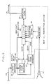
- FIG. 1 is a block diagram of a unidirectional open-ring serial transmit/receive network architecture in accordance with the present invention;
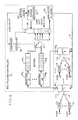
- FIG. 2 is a block diagram of an exemplary BUS/RBIU transmitter interface architecture without regeneration;
- Fig. 3 is a block diagram of an exemplary BUS/RBIU transmitter interface architecture with regeneration;
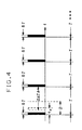
- FIG. 4 is an exemplary time frame format for use in the present network arrangement;
- FIG. 5 is a block diagram of an exemplary Bus/RBIU receiver interface in accordance with the present invention; and
- FIG. 6 is a block diagram of an unidirectional open-ring parallel transmit/serial receive network architecture with a multiplexer/controller in accordance with the present invention.
- The present invention relates to a high-speed high-capacity Local Area Network (LAN) wherein the users of the network communicate cordlessly, using radio frequencies (RF) or infrared (IR), with an assigned one of a plurality of Region Bus Interface Units (RBIUs) located in each user's proximity. The RBIUs also interface with a bus of the network in any suitable arrangement such as, for example, a serial open ring arrangement, as shown in FIG. 1, or a parallel transmit/serial receive open ring arrangement as shown in FIG. 6. Other suitable arrangements which might be applicable for use are, for example, that of the FASNET network arrangement shown in FIG. 2 of the article by J. O. Limb et al. in The Bell System Technical Journal, Vol. 61, No. 7, September 1982, at pages 1413-1440; and the D-Net and other arrangements described by C-W. Tseng et al. in IEEE Journal On Selected Areas In Communication, Vol. SAC-1, No. 3, April 1983, at pages 493-499.
- FIG. 1 is a block diagram of a serial open-ring network in accordance with the present invention. More particularly, each user of the network includes an associated
transceiver 10 which communicates signaling and data information cordlessly, via radio frequencies of a few GHz or via infrared, to a particular one of a plurality ofN RBIUs 11₁ to 11 N . The plurality of N RBIUs are distributed at selected points around the network's service area, and each RBIU 11 i shared by, for example, up to M i separate users located in its proximity. For such arrangement, a cellular frequency division arrangement of carriers, as is well-known and used in cellular mobile radio systems, can be used by adjacent RBIUs to control interference. Thus, in a commercial office environment, for example, where many people with telephones and/or computer terminals sit in a single large room, a ceiling-mountedwide angle antenna 12 at the associated RBIU 11 i can be used for communications between the RBIU and the plurality of associated M i end-user transceivers 10. In other office environments, where many small individual rooms are close to one another, an RBIU 11 i can serve a small cluster of rooms in a similar manner. Communication between the M i users and the associated RBIU 11 i can be accomplished, for example, by Time Division Multiple Access (TDMA), Frequency Division Multiple Access (FDMA), the slotted ALOHA protocol or any other suitable method. For purposes of discussion, and not for purposes of limitation, it will be assumed hereinafter that (a) the network uses TDMA techniques along a bus; (b) each RBIU 11 i processes the signals from the associated users into separate packets of information, including necessary control information, for transmission on abus 14 to the destined users; and (c) the present network under discussion is an optical LAN transmitting lightwave signals alongbus 14 which is an optical waveguide such as a single mode optical fiber bus. - In the serial open-ring network arrangement of FIG. 1, a Frame Marker Generator 15 is located at the head-end of
bus 14 for dividing the time onbus 14 into equal frames of duration T, as shown in FIG. 4. The markers transmitted by Frame MarkerGenerator 15 at the beginning of each frame serve as a source of synchronization for the entire network and consist of a periodic light modulated sequence of bits, of duration δT, transmitted every T seconds, with δT « T. This function can also be incorporated on a standby basis within the first few RBIUs alongbus 14 to increase the reliability of the network in case of a failure of Frame Marker Generator 15 at the head-end ofbus 14. Alternatively, the frame marking function can be directly performed within the first RBIU 11₁ in place of Frame Marker Generator 15 with the next few succeeding RBIUs providing standby operation. Each of theRBIUs 11₁ to 11 N appropriately formats the signals from each of the associated M users into separate packets of information and, after detecting the markers fromFrame Marker Generator 15 and then sensing that a frame is not being used by previous RBIUs onbus 14, the RBIU transmits a packet of information ontobus 14 during a detected empty frame period. - FIG. 2 is a block diagram of the transmitter section of an RBIU 11 i which uses no regeneration of the signal on
bus 14, while FIG. 3 is a block diagram of the transmitter section of an RBIU using regeneration. In the transmitter section of FIGs. 2 and 3, either a small part (FIG. 2) of, or all (FIG. 3) of, the light-modulated bit stream fromserial bus 14 is demodulated by aphoto detector 20 to, for example, baseband. This demodulated signal is received by both a Clock andFrame Recovery circuit 21 and anEmpty Frame Detector 22. Clock andframe recovery circuit 21 functions to recover the frame markers generated by Frame MarkerGenerator 15 out of which a bit clock is generated. TheEmpty Frame Detector 22 receives the recovered frame markers fromrecovery circuit 21 and scan the the frame during the time interval t o , shown in FIG. 4, to determine whether the frame is occupied or not by a packet of information transmitted by one of the prior RBIUs 11 onbus 14. Time interval t o may typically be δT plus a few bits in duration, or t o approximates δT. - If the frame is occupied with a packet of information transmitted by one of the preceding RBIUs 11, this packet of information will continue traveling on
bus 14, in the arrangement of FIG. 2, throughanalog delay 23 preferably with very low attenuation. In FIG. 3, however, the packet of information frombus 14 is regenerated by serially feeding the packet through adigital delay circuit 24 to a VeryFast Register 25 whose output modulates alaser light source 26 which has its output coupled tobus 14 for sending the modulated packet of information forward. In the arrangements of either one of FIGs. 2 or 3, if one or more end users have transmitted a signal to the associated RBIU 11 i , this signal is received by the RBIU'santenna 12 for delivery to areceiver 27. It is to be understood that users 1-M i associated with an RBIU 11 i can transmit asynchronously using any suitable technique described hereinbefore, and thatreceiver 27 is arranged to receive such asynchronously transmitted signals and process them separately. Receiver 27 functions to collect the information received from each user, formats the information of each used by adding any required overhead protocol, buffers the formatted packet(s) if necessary, and transmits each formatted packet to atransmitter buffer 28 at the appropriate time. - Upon the receipt of a "Load" enable signal from
Empty Frame Detector 22,transmitter buffer 28 transfers the packet stored therein in a parallel manner intoshift register 25. WhenEmpty Frame detector 22 generates a "shift" enable signal, the packet inshift register 25 is delivered in serial fashion tomodulator laser 26 at the bit clock rate from Clock andFrame Recovery circuit 21 for transmission ontoserial bus 14. The delay D in FIG. 4, which is analog in the arrangement of FIG. 2 and digital in the arrangement of FIG. 3, is of sufficient duration to enable the multiplexing of a packet of information fromTransmitter Buffer 28 into a frame on the bus once that same frame is determined to be unoccupied. The delay D is approximately equal to t o plus, for example, up to 20 bits in duration. - This interface protocol is collision-free and, therefore, very efficient. As long as there is a packet of information for transmission in
Transmitter Buffer 28, it will be multiplexed ontobus 14 in the immediately detected unoccupied frame. When a packet of information becomes available inTransmitter Buffer 28 past the decision of an unoccupied frame byEmpty Frame Detector 22, it will have to wait until the next unoccupied frame comes along. - The architecture of the receiver section of an RBIU 11 i for either one of the network arrangement of FIGs. 1 and 6 is shown in FIG. 5. There, a small portion of the light modulated bit stream propagating along
bus 14 is received by aphoto detector 30 via an R-directional coupler 31.Photo detector 30 functions in the manner described forphoto detector 20 in the transmit section of an RBIU 11. The demodulated signal fromphoto detector 30 is delivered to both a Clock andFrame Detector circuit 32, which recovers the clock and frame markers from the received bit stream, and a veryfast shift register 33 into which the received bit stream is serially fed. In response to enable signals fromdetector 32, register 33 is unloaded in parallel into a Message Decoder andBuffer 34. - In Message Decoder and Buffer 34 a decision is made, based upon the address of destination provided in the overhead portion of the packet of information, whether to discard or store the message in an included buffer. More particularly, if a packet of information includes an address destination for one of the users associated with this particular RBIU, then the packet of information is buffered, otherwise it is discarded. Messages stored in Decoder and
Buffer 34 are then modulated in a Very Low Power RF Transmitter andModulator 35 and broadcasted byantenna 12, using RF or IR, to all associated end users. In FIG. 1, anoptional PBX controller 16 is shown included at the ends ofbus 14 for use when the LAN serves as a PBX distribution network for bursty or variable rate wide band communications. - FIG. 6 shows an implementation of the present invention in the form of a parallel transmit/serial receive network. In the network of FIG. 6, the interchange between the users, the RBIUs 11, and the receiver bus is similar to that described hereinbefore for the network of FIG. 1. However, since the
RBIUs 11₁ to 11 N now transmit the formatted packets of information on separate buses 40₁ to 40 N respectively, to a Multiplexer/Controller (M/C) 41, the transmissions between the RBIUs 11 and M/C 41 are at the RBIU rate and can be asynchronous. In the parallel transmit part of the network of FIG. 6, theRBIUs 11₁ to 11 N independently deposit their packets of information inbuffers 43₁ to 43 N respectively, viarespective receivers 44₁ to 44 N . A sequencer andcontroller 45 cyclically controls the loading, in parallel, of the packets of information frombuffers 43 into a VeryFast Shift Register 46 via a switching means 47. - A
master clock 48 in M/C 41 controls the data transfer betweenbuffers 43, switching means 47 andRegister 46 as well as the fast serial shifting of the bits from theFrame Marker Generator 49 into a Modulator andLaser circuit 50.Frame Marker Generator 49 functions as described forFrame Marker Generator 15 in the network of FIG. 1 to insert a marker at the beginning of each packet to be sent overbus 14. Incircuit 50, the laser is modulated by the serially received packet of information fromregister 46. The modulated bit stream is fed into the high-speed bus 14 where the transmission is synchronous. - Flexibility can be built, under software control, into M/
C 41 for multiplexing the packets of information from thevarious buffers 43 ontobus 14. For example, one or a fixed number of packets of information from eachbuffer 43 i could be cyclically multiplexed, or eachbuffer 43 could be emptied of its packets of information before preceding to the next buffer. Priorities could also be easily assigned tocertain buffers 43 under program control. From a hardware point of view, the network of FIG. 6 is simpler than the serial network of FIG. 1, since the Sense (S) and Transmit (T) directional couplers nor thelaser 26 and VeryFast Shift Register 25 in the transmitter of each RBIU 11 would be needed. The lower speed of the parallel transmissions on buses 40₁ to 40 N of FIG. 6 would permit the use of, for example, multimode fibers and LED sources for a lightwave network of FIG. 6. The only disadvantage is the need for more buses in the parallel transmit connection. The very high-speed components, however, would still be needed in the receiver sections of the RBIUs 11 of FIG. 6 as well as in M/C 41, which is shared by all RBIUs 11. Most of the lower speed components could be integrated and implemented in TTL, ECL, CMOS, etc. - In accordance with the present invention, locating the RBIUs 11 close to their cordless end users has many advantages, among them are that (a) local communications can be achieved at very low power levels thus eliminating radiation hazards and interference problems; (b) due to the short radio paths involved, multipath dispersion is sufficiently small such that burst data rates of, for example, 20-50 Mbit/s may be possible for the local communications; and (c) simple communications protocol such as, for example, CSMA/CD, slotted ALOHA, etc., can be employed by the end users with high efficiency due to the short paths involved relative to the frame durations. Additionally, the following advantages are achieved by buffering the end users from the high-speed bus by the RBIUs: (a) the high-speed bus is not burdened with the end-user communications protocol; (b) the high-speed bus can be efficiently utilized with relatively insignificant waiting time delay penalty; (c) even at 100% utilization, the high-speed bus operation is stable.
Claims (15)
a communications bus (14,40) which is routed along a predetermined path within an area to be serviced by the LAN; and
a plurality of regional bus interface units (11) (RBIUs) disposed at separate selected points around the area to be serviced by the LAN,
CHARACTERIZED IN THAT
each RBIU comprises;
means (12, 27, FIG. 2-3; 12, 35, FIG. 5) for providing cordless, low-level radiation, two-way communications between the RBIU and each user of a separate group of one or more network users assigned to, and located in, the proximity of the RBIU using a predetermined communications protocol;
means (20-22,25-26,28, FIGs. 2-3) for transmitting information signals received from a user of the group assigned to the RBIU onto the communications bus in a predetermined format including a destination user's address; and
means (30, 32-34, FIG. 5) for (a) receiving formatted information signals propagating on the communications bus, (b) detecting from an included destination user's address whether or not each received information signal is destined for a user of the group of users assigned to the RBIU, and (c) delivering an information signal destined for one said of network users to the cordless two-way transmission means for transmission to the destined user.
CHARACTERIZED IN THAT
the LAN further comprises:
means for generating periodic frame marker signals for propagation along the communications bus, each frame marker signal indicating the beginning of a frame in which a formatted information signal can be transmitted.
CHARACTERIZED IN THAT
the generating means is disposed at the head end of the communications bus.
CHARACTERIZED ON THAT
the generating means is disposed within the RBIU nearest a head end of the communications bus.
CHARACTERIZED IN THAT
the transmitting means comprises:
means (22) for (a) detecting both a frame marker signal propagating on the communications bus and whether or not a formatted information signal occupies the remainder of a frame period, and (b) generating an output control signal whenever a formatted information signal does not occupy the remainder of a frame period;
means (25) for sorting a formatted information signal to be transmitted over the communications bus and for transmitting the formatted information signal onto the bus in response to the output control signal from the detecting and generating means.
CHARACTERIZED IN THAT
the receiving means comprises:
means (32) for detecting a frame marker signal propagating on the communications bus and for generating an output control signal whenever the frame marker signal is detected;
means (33) responsive to the output control signal from the detecting and generating means for temporarily storing information received from the communications bus in the frame period associated with the detected frame marker signal; and
means (34, 35) responsive to the information stored in the storing means for determining from the included destination user's address whether or not the received information signal is destined for a user of the group assigned to the RBIU, and for cordlessly transmitting each information signal destined for a user of said group to that user.
CHARACTERIZED IN THAT
the communications bus is a lightguide for propagating optical signals.
CHARACTERIZED IN THAT
the communications bus is capable of propagating electrical signals.
CHARACTERIZED IN THAT
the RBIU comprises:
a first and a second input terminal and an output terminal;
means for providing cordless, low-level radiation, two-way transmissions of information signals between the RBIU and each user of a group of one or more users assigned to the RBIU;
means connected between the first input terminal and the output terminal for (a) detecting when a formatted information signal is not received at the first input terminal during a predetermined time period, and (b) transmitting information signals received from a user of the group of one or more users assigned to the RBIU in a predetermined format including a destination user's address to the output terminal during the detected time period; and
means coupled to the second input terminal for (a) receiving formatted information signals from the second input terminal, (b) detecting from an included destination user's address whether or not a received information signal is destined for a user of the group of one or more users assigned to the RBIU, and (c) delivering an information signal destined for a user of the group to the cordless two-way transmission means for transmission to the destined user.
CHARACTERIZED IN THAT
the transmitting means comprises:
means for (a) detecting both a periodic frame marker signal received at the first input terminal, which frame marker signal is disposed at the start of a frame period, and whether or not a formatted information signal is received at the first input terminal during the remainder of the frame period, and (b) for generating an output control signal whenever a formatted information signal is not received at the first input terminal during a frame period; and
means for storing a formatted information signal to be delivered to the output terminal and for transmitting the formatted information signal to the output terminal in response to the output control signal from the detecting and generating means.
CHARACTERIZED IN THAT
the receiving means comprises:
means for detecting a frame marker signal received at the second input terminal and for generating an output signal whenever a frame marker signal is detected;
means responsive to the output control signal from the detecting and generating means for temporarily storing an information signal received at the second input terminal in a frame period associated with a frame marker signal; and
means responsive to the information signal stored in the storing means for determining from the included destination user's address whether or not the received information signal is destined for a user of the group assigned to the RBIU, and for cordlessly transmitting each information signal destined for a user of the group to that user.
CHARACTERIZED IN THAT
the first and second input terminals are arranged to receive lightwave signals and the transmitting means is arranged to transmit lightwave signals to the output terminal.
CHARACTERIZED IN THAT
the first and second input terminals are arranged to receive electrical signals and the transmitting means is arranged to transmit electrical signals to the output terminal.
CHARACTERIZED IN THAT
the cordless transmission means provides two-way communications with the user of the group using radio frequency signals.
CHARACTERIZED IN THAT
the cordless transmission means provides two-way communications with the users of the group using infrared signals.
Applications Claiming Priority (2)
| Application Number | Priority Date | Filing Date | Title |
|---|---|---|---|
| US06/899,647 US4807222A (en) | 1986-08-25 | 1986-08-25 | Cordless accessed high-speed high-capacity local area networks |
| US899647 | 1986-08-25 |
Publications (3)
| Publication Number | Publication Date |
|---|---|
| EP0257947A2 true EP0257947A2 (en) | 1988-03-02 |
| EP0257947A3 EP0257947A3 (en) | 1990-05-02 |
| EP0257947B1 EP0257947B1 (en) | 1994-03-30 |
Family
ID=25411341
Family Applications (1)
| Application Number | Title | Priority Date | Filing Date |
|---|---|---|---|
| EP87307235A Expired - Lifetime EP0257947B1 (en) | 1986-08-25 | 1987-08-17 | Cordless accessed high-speed high-capacity local area networks |
Country Status (5)
| Country | Link |
|---|---|
| US (1) | US4807222A (en) |
| EP (1) | EP0257947B1 (en) |
| JP (1) | JPS6360643A (en) |
| CA (1) | CA1270304A (en) |
| DE (1) | DE3789474T2 (en) |
Cited By (8)
| Publication number | Priority date | Publication date | Assignee | Title |
|---|---|---|---|---|
| EP0403203A2 (en) * | 1989-06-16 | 1990-12-19 | Libera Telecom Limited | Communication systems |
| EP0483548A1 (en) * | 1990-10-29 | 1992-05-06 | International Business Machines Corporation | Transceiver for extending a CSMA/CD network for wireless communication |
| EP0496986A2 (en) * | 1990-12-28 | 1992-08-05 | Symbol Technologies, Inc. | Packet data communication system |
| EP0526106A2 (en) * | 1991-07-31 | 1993-02-03 | AT&T Corp. | Integrated wireless telecommunication and local area network system |
| WO1993007684A1 (en) * | 1991-10-07 | 1993-04-15 | Sixtel S.P.A. | Cordless local area network (radio lan) with central unit |
| DE4232481A1 (en) * | 1992-09-28 | 1993-11-25 | Siemens Ag | Cordless communication arrangement with mobile end devices - has both first transmitter receiver apparatus and mobile end devices having cordless telephone standard procedure realising components |
| FR2713421A1 (en) * | 1993-12-06 | 1995-06-09 | Alcatel Business Systems | Local network with radio transmission. |
| WO1997029571A1 (en) * | 1996-02-12 | 1997-08-14 | Hewlett-Packard Company | Signal transmission between networked computers |
Families Citing this family (122)
| Publication number | Priority date | Publication date | Assignee | Title |
|---|---|---|---|---|
| CA1290020C (en) * | 1987-02-09 | 1991-10-01 | Steven Messenger | Wireless local area network |
| US5682256A (en) * | 1988-11-11 | 1997-10-28 | British Telecommunications Public Limited Company | Communications system |
| JPH02162857A (en) * | 1988-12-15 | 1990-06-22 | Hamamatsu Photonics Kk | Communication method using light and radio wave |
| US4979231A (en) * | 1989-01-06 | 1990-12-18 | Motorola, Inc. | Two-way radio for use in a communication system |
| US6614768B1 (en) | 1989-04-28 | 2003-09-02 | Broadcom Corporation | Enhanced mobility and address resolution in a wireless premises based network |
| US5159695A (en) * | 1989-05-30 | 1992-10-27 | Motorola, Inc. | Communication system to communication system communication system |
| US5860136A (en) * | 1989-06-16 | 1999-01-12 | Fenner; Peter R. | Method and apparatus for use of associated memory with large key spaces |
| US5022047A (en) * | 1989-08-07 | 1991-06-04 | Omnipoint Data Corporation | Spread spectrum correlator |
| US5499265A (en) * | 1989-08-07 | 1996-03-12 | Omnipoint Data Company, Incorporated | Spread spectrum correlator |
| US5016255A (en) * | 1989-08-07 | 1991-05-14 | Omnipoint Data Company, Incorporated | Asymmetric spread spectrum correlator |
| US5477541A (en) * | 1989-09-29 | 1995-12-19 | White; Richard E. | Addressing technique for storing and referencing packet data |
| US5495482A (en) * | 1989-09-29 | 1996-02-27 | Motorola Inc. | Packet transmission system and method utilizing both a data bus and dedicated control lines |
| US5166932A (en) * | 1990-04-27 | 1992-11-24 | Seiko Corp. | Wireless facsimile computer slate |
| US5166952A (en) * | 1990-05-24 | 1992-11-24 | Cylink Corporation | Method and apparatus for the reception and demodulation of spread spectrum radio signals |
| US5253268A (en) * | 1990-05-24 | 1993-10-12 | Cylink Corporation | Method and apparatus for the correlation of sample bits of spread spectrum radio signals |
| US5157686A (en) * | 1990-05-24 | 1992-10-20 | Cylink Corporation | Method and apparatus for the modulation of spread spectrum radio signals |
| JPH05509213A (en) * | 1990-07-23 | 1993-12-16 | オムニポイント・コーポレイション | SAWC phase detection method and device |
| US5081642A (en) * | 1990-08-06 | 1992-01-14 | Omnipoint Data Company, Incorporated | Reciprocal saw correlator method and apparatus |
| GB9019488D0 (en) * | 1990-09-06 | 1990-10-24 | Ncr Co | Local area network having a wireless transmission link |
| WO1992007434A1 (en) * | 1990-10-23 | 1992-04-30 | Omnipoint Corporation | Method and apparatus for establishing spread spectrum communications |
| US5239673A (en) * | 1990-10-29 | 1993-08-24 | International Business Machines Corporation | Scheduling methods for efficient frequency reuse in a multi-cell wireless network served by a wired local area network |
| US5159592A (en) * | 1990-10-29 | 1992-10-27 | International Business Machines Corporation | Network address management for a wired network supporting wireless communication to a plurality of mobile users |
| US5181200A (en) * | 1990-10-29 | 1993-01-19 | International Business Machines Corporation | Handoff method and apparatus for mobile wireless workstation |
| JP2511591B2 (en) * | 1990-10-29 | 1996-06-26 | インターナショナル・ビジネス・マシーンズ・コーポレイション | Wireless optical communication system operating method and optical communication system |
| US5274841A (en) * | 1990-10-29 | 1993-12-28 | International Business Machines Corporation | Methods for polling mobile users in a multiple cell wireless network |
| US5212806A (en) * | 1990-10-29 | 1993-05-18 | International Business Machines Corporation | Distributed control methods for management of migrating data stations in a wireless communications network |
| US5068916A (en) * | 1990-10-29 | 1991-11-26 | International Business Machines Corporation | Coordination of wireless medium among a plurality of base stations |
| JP2500963B2 (en) | 1990-10-29 | 1996-05-29 | インターナショナル・ビジネス・マシーンズ・コーポレイション | Two-way information communication method |
| US6873643B2 (en) | 1990-11-16 | 2005-03-29 | Interdigital Technology Corporation | Spread spectrum adaptive power control communications system and method |
| US5299226A (en) * | 1990-11-16 | 1994-03-29 | Interdigital Technology Corporation | Adaptive power control for a spread spectrum communications system and method |
| US5535238A (en) | 1990-11-16 | 1996-07-09 | Interdigital Technology Corporation | Spread spectrum adaptive power control communications system and method |
| US5161168A (en) * | 1991-05-15 | 1992-11-03 | Scs Mobilecom, Inc. | Spread spectrum CDMA communications system microwave overlay |
| US5185762A (en) * | 1991-05-15 | 1993-02-09 | Scs Mobilecom, Inc. | Spread spectrum microwave overlay with notch filter |
| US7020125B2 (en) * | 1990-12-05 | 2006-03-28 | Interdigital Technology Corporation | Broadband CDMA overlay system and method |
| US5351269A (en) * | 1990-12-05 | 1994-09-27 | Scs Mobilecom, Inc. | Overlaying spread spectrum CDMA personal communications system |
| US5263045A (en) * | 1990-12-05 | 1993-11-16 | Interdigital Technology Corporation | Spread spectrum conference call system and method |
| US5228056A (en) * | 1990-12-14 | 1993-07-13 | Interdigital Technology Corporation | Synchronous spread-spectrum communications system and method |
| US5703874A (en) * | 1990-12-05 | 1997-12-30 | Interdigital Technology Corporation | Broadband CDMA overlay system and method |
| US5506864A (en) * | 1990-12-05 | 1996-04-09 | Interdigital Technology Corporation | CDMA communications and geolocation system and method |
| US5274665A (en) * | 1990-12-14 | 1993-12-28 | Interdigital Technology Corporation | Polyopoly overlapping spread spectrum communication system and method |
| CA2054591C (en) * | 1991-02-28 | 1996-09-03 | Giovanni Vannucci | Wireless telecommunication systems |
| US5402413A (en) * | 1991-04-08 | 1995-03-28 | Omnipoint Corporation | Three-cell wireless communication system |
| DE69232943T2 (en) * | 1991-05-13 | 2003-08-28 | Xircom Wireless Inc | TRANSMITTER / RECEIVER WITH TWO OPERATING MODES |
| US5694414A (en) * | 1991-05-13 | 1997-12-02 | Omnipoint Corporation | Multi-band, multi-mode spread-spectrum communication system |
| US5790587A (en) * | 1991-05-13 | 1998-08-04 | Omnipoint Corporation | Multi-band, multi-mode spread-spectrum communication system |
| US6714559B1 (en) * | 1991-12-04 | 2004-03-30 | Broadcom Corporation | Redundant radio frequency network having a roaming terminal communication protocol |
| US5815525A (en) * | 1991-05-13 | 1998-09-29 | Omnipoint Corporation | Multi-band, multi-mode spread-spectrum communication system |
| US5887020A (en) * | 1991-05-13 | 1999-03-23 | Omnipoint Corporation | Multi-band, multi-mode spread-spectrum communication system |
| US5796772A (en) * | 1991-05-13 | 1998-08-18 | Omnipoint Corporation | Multi-band, multi-mode spread-spectrum communication system |
| US5228053A (en) * | 1991-05-15 | 1993-07-13 | Interdigital Technology Corporation | Spread spectrum cellular overlay CDMA communications system |
| US5166951A (en) * | 1991-05-15 | 1992-11-24 | Scs Mobilecom, Inc. | High capacity spread spectrum channel |
| USRE38627E1 (en) * | 1991-05-15 | 2004-10-19 | Interdigital Technology Corp. | High capacity spread spectrum channel |
| US5235615A (en) * | 1991-05-22 | 1993-08-10 | Cylink Corporation | Spread spectrum method |
| US5285469A (en) | 1991-06-03 | 1994-02-08 | Omnipoint Data Corporation | Spread spectrum wireless telephone system |
| US5345467A (en) * | 1991-07-10 | 1994-09-06 | Interdigital Technology Corp. | CDMA cellular hand-off apparatus and method |
| JP2897492B2 (en) * | 1991-10-24 | 1999-05-31 | 日本電気株式会社 | Mobile communication device |
| IE922611A1 (en) * | 1991-10-30 | 1993-05-05 | Motorola Inc | Method for data collision detection in a multi processor¹communication system |
| US5210753A (en) * | 1991-10-31 | 1993-05-11 | International Business Machines Corporation | Robust scheduling mechanm for efficient band-width usage in muliticell wireless local networks |
| AU3324893A (en) * | 1991-12-16 | 1993-07-19 | Omnipoint Corporation | Spread-spectrum data publishing system |
| US5442633A (en) * | 1992-07-08 | 1995-08-15 | International Business Machines Corporation | Shortcut network layer routing for mobile hosts |
| GB9217374D0 (en) * | 1992-08-14 | 1992-09-30 | Ncr Int Inc | Wireless local area network transmission system |
| US5355389A (en) * | 1993-01-13 | 1994-10-11 | Omnipoint Corporation | Reciprocal mode saw correlator method and apparatus |
| US5796727A (en) * | 1993-04-30 | 1998-08-18 | International Business Machines Corporation | Wide-area wireless lan access |
| US5774738A (en) * | 1993-05-03 | 1998-06-30 | Texas Instruments Incorporated | State machines |
| US5696903A (en) * | 1993-05-11 | 1997-12-09 | Norand Corporation | Hierarchical communications system using microlink, data rate switching, frequency hopping and vehicular local area networking |
| US6970434B1 (en) * | 1995-06-07 | 2005-11-29 | Broadcom Corporation | Hierarchical communication system providing intelligent data, program and processing migration |
| IL105990A (en) * | 1993-06-11 | 1997-04-15 | Uri Segev And Benjamin Machnes | Infra-red communication system |
| WO1995001020A1 (en) * | 1993-06-25 | 1995-01-05 | Xircom, Incorporated | Virtual carrier detection for wireless local area network with distributed control |
| JP2502468B2 (en) * | 1993-09-30 | 1996-05-29 | インターナショナル・ビジネス・マシーンズ・コーポレイション | Communication control method for a local wireless communication system having a plurality of wireless mobile stations |
| US5666379A (en) * | 1993-11-01 | 1997-09-09 | Omnipoint Corporation | Best-of-M pulse position modulation detector |
| US6094575A (en) * | 1993-11-01 | 2000-07-25 | Omnipoint Corporation | Communication system and method |
| US6005856A (en) * | 1993-11-01 | 1999-12-21 | Omnipoint Corporation | Communication protocol for spread spectrum wireless communication system |
| US5436941A (en) * | 1993-11-01 | 1995-07-25 | Omnipoint Corporation | Spread spectrum spectral density techniques |
| US5654978A (en) * | 1993-11-01 | 1997-08-05 | Omnipoint Corporation | Pulse position modulation with spread spectrum |
| WO1995012945A1 (en) * | 1993-11-01 | 1995-05-11 | Omnipoint Corporation | Despreading/demodulating direct sequence spread spectrum signals |
| US6088590A (en) | 1993-11-01 | 2000-07-11 | Omnipoint Corporation | Method and system for mobile controlled handoff and link maintenance in spread spectrum communication |
| US5699353A (en) * | 1993-11-24 | 1997-12-16 | Ericsson Ge Mobile Communications, Inc. | Extended trunked RF communications systems networking |
| US5553074A (en) * | 1994-03-04 | 1996-09-03 | Trustees Of Columbia University In The City Of New York | Transmission format in packet based communications |
| JPH07264177A (en) * | 1994-03-25 | 1995-10-13 | Matsushita Electric Ind Co Ltd | Parallel signal optical transmission system |
| US5856998A (en) * | 1994-09-09 | 1999-01-05 | Omnipoint Corporation | Method and apparatus for correlating a continuous phase modulated spread spectrum signal |
| US5680414A (en) * | 1994-09-09 | 1997-10-21 | Omnipoint Corporation | Synchronization apparatus and method for spread spectrum receiver |
| US5754585A (en) * | 1994-09-09 | 1998-05-19 | Omnipoint Corporation | Method and apparatus for serial noncoherent correlation of a spread spectrum signal |
| US5659574A (en) * | 1994-09-09 | 1997-08-19 | Omnipoint Corporation | Multi-bit correlation of continuous phase modulated signals |
| US5953370A (en) * | 1994-09-09 | 1999-09-14 | Omnipoint Corporation | Apparatus for receiving and correlating a spread spectrum signal |
| US5610940A (en) * | 1994-09-09 | 1997-03-11 | Omnipoint Corporation | Method and apparatus for noncoherent reception and correlation of a continous phase modulated signal |
| US5832028A (en) * | 1994-09-09 | 1998-11-03 | Omnipoint Corporation | Method and apparatus for coherent serial correlation of a spread spectrum signal |
| US5627856A (en) * | 1994-09-09 | 1997-05-06 | Omnipoint Corporation | Method and apparatus for receiving and despreading a continuous phase-modulated spread spectrum signal using self-synchronizing correlators |
| US5757847A (en) * | 1994-09-09 | 1998-05-26 | Omnipoint Corporation | Method and apparatus for decoding a phase encoded signal |
| US5754584A (en) * | 1994-09-09 | 1998-05-19 | Omnipoint Corporation | Non-coherent spread-spectrum continuous-phase modulation communication system |
| US5963586A (en) * | 1994-09-09 | 1999-10-05 | Omnipoint Corporation | Method and apparatus for parallel noncoherent correlation of a spread spectrum signal |
| US5692007A (en) * | 1994-09-09 | 1997-11-25 | Omnipoint Corporation | Method and apparatus for differential phase encoding and decoding in spread-spectrum communication systems with continuous-phase modulation |
| US5629956A (en) * | 1994-09-09 | 1997-05-13 | Omnipoint Corporation | Method and apparatus for reception and noncoherent serial correlation of a continuous phase modulated signal |
| US5648982A (en) * | 1994-09-09 | 1997-07-15 | Omnipoint Corporation | Spread spectrum transmitter |
| US5881100A (en) * | 1994-09-09 | 1999-03-09 | Omnipoint Corporation | Method and apparatus for coherent correlation of a spread spectrum signal |
| US5742583A (en) * | 1994-11-03 | 1998-04-21 | Omnipoint Corporation | Antenna diversity techniques |
| US5657326A (en) * | 1994-12-20 | 1997-08-12 | 3Com Corporation | Radio based collision detection for wireless communication system |
| US5745479A (en) * | 1995-02-24 | 1998-04-28 | 3Com Corporation | Error detection in a wireless LAN environment |
| US9191117B2 (en) * | 1995-05-11 | 2015-11-17 | Ciena Corporation | High-speed optical transponder systems |
| US5959980A (en) | 1995-06-05 | 1999-09-28 | Omnipoint Corporation | Timing adjustment control for efficient time division duplex communication |
| US5802046A (en) * | 1995-06-05 | 1998-09-01 | Omnipoint Corporation | Efficient time division duplex communication system with interleaved format and timing adjustment control |
| US5689502A (en) * | 1995-06-05 | 1997-11-18 | Omnipoint Corporation | Efficient frequency division duplex communication system with interleaved format and timing adjustment control |
| US5745484A (en) * | 1995-06-05 | 1998-04-28 | Omnipoint Corporation | Efficient communication system using time division multiplexing and timing adjustment control |
| US6041046A (en) * | 1995-07-14 | 2000-03-21 | Omnipoint Corporation | Cyclic time hopping in time division multiple access communication system |
| US6300880B1 (en) * | 1996-01-16 | 2001-10-09 | Philips Electronics North America Corp. | Multichannel audio distribution system having portable receivers |
| US5880863A (en) * | 1996-02-13 | 1999-03-09 | Gte Laboratories Incorporated | Reconfigurable ring system for the transport of RF signals over optical fibers |
| US6002664A (en) * | 1997-02-24 | 1999-12-14 | At&T Wireless Services Inc. | Method to gain access to a base station in a discrete multitone spread spectrum communications system |
| US6081356A (en) * | 1997-05-27 | 2000-06-27 | Steelcase Development Inc. | Integrated optical ports |
| US6239888B1 (en) | 1998-04-24 | 2001-05-29 | Lightpointe Communications, Inc. | Terrestrial optical communication network of integrated fiber and free-space links which requires no electro-optical conversion between links |
| US6868237B2 (en) | 1998-04-24 | 2005-03-15 | Lightpointe Communications, Inc. | Terrestrial optical communication network of integrated fiber and free-space links which requires no electro-optical conversion between links |
| US6337856B1 (en) | 1998-05-20 | 2002-01-08 | Steelcase Development Corporation | Multimedia data communications system |
| US6359711B1 (en) | 1998-05-20 | 2002-03-19 | Steelcase Development Corporation | System and method for supporting a worker in a distributed work environment |
| US6298047B1 (en) | 1998-05-20 | 2001-10-02 | Steelcase Development Inc. | Method and apparatus for establishing a data link between a portable data communications device and an interface circuit |
| US6947469B2 (en) | 1999-05-07 | 2005-09-20 | Intel Corporation | Method and Apparatus for wireless spread spectrum communication with preamble processing period |
| SG109407A1 (en) * | 1999-05-28 | 2005-03-30 | Kent Ridge Digital Labs | Wireless communications link |
| US20040165890A1 (en) * | 1999-11-08 | 2004-08-26 | Throughput Holdings, Inc. | Wide-signal bandwidth multi-access channel |
| US6763195B1 (en) * | 2000-01-13 | 2004-07-13 | Lightpointe Communications, Inc. | Hybrid wireless optical and radio frequency communication link |
| US6889009B2 (en) * | 2001-04-16 | 2005-05-03 | Lightpointe Communications, Inc. | Integrated environmental control and management system for free-space optical communication systems |
| US20020171896A1 (en) * | 2001-05-21 | 2002-11-21 | Lightpointe Communications, Inc. | Free-space optical communication system employing wavelength conversion |
| US20030090765A1 (en) * | 2001-11-09 | 2003-05-15 | Neff Brian W. | Free-space optical communication system |
| US20060140642A1 (en) * | 2004-12-29 | 2006-06-29 | Brolin Stephen J | Eliminating ONU laser for WDM PON by burst mode |
| US8233802B2 (en) * | 2009-12-31 | 2012-07-31 | At&T Intellectual Property I, L.P. | Portable infrared control liaison |
| US9083638B2 (en) * | 2012-02-10 | 2015-07-14 | Empire Technology Development Llc | Data transmission in cloud-based system |
Citations (1)
| Publication number | Priority date | Publication date | Assignee | Title |
|---|---|---|---|---|
| US4402090A (en) * | 1980-12-23 | 1983-08-30 | International Business Machines Corp. | Communication system in which data are transferred between terminal stations and satellite stations by infrared signals |
Family Cites Families (9)
| Publication number | Priority date | Publication date | Assignee | Title |
|---|---|---|---|---|
| JPS5148845B2 (en) * | 1971-11-08 | 1976-12-23 | ||
| US4291197A (en) * | 1978-05-31 | 1981-09-22 | Maruyoshi Sangyo Kabushiki Kaisha | Remote telephone system |
| JPS56122253A (en) * | 1980-02-29 | 1981-09-25 | Nec Corp | Signal transmission system |
| US4503533A (en) * | 1981-08-20 | 1985-03-05 | Stanford University | Local area communication network utilizing a round robin access scheme with improved channel utilization |
| NL8104104A (en) * | 1981-09-04 | 1983-04-05 | Philips Nv | DISTRIBUTION SYSTEM FOR A LOCAL FIBERNET. |
| JPS5954347A (en) * | 1982-09-22 | 1984-03-29 | Fujitsu Ltd | System for adjusting timing of channel insertion |
| US4574284A (en) * | 1983-01-26 | 1986-03-04 | Trw Inc. | Communication bus interface unit |
| IT1179081B (en) * | 1984-08-28 | 1987-09-16 | Cselt Centro Studi Lab Telecom | INTEGRATED BROADBAND COMMUNICATION SYSTEM IN THE LOCAL AREA |
| US4665519A (en) * | 1985-11-04 | 1987-05-12 | Electronic Systems Technology, Inc. | Wireless computer modem |
-
1986
- 1986-08-25 US US06/899,647 patent/US4807222A/en not_active Expired - Lifetime
-
1987
- 1987-07-30 CA CA000543457A patent/CA1270304A/en not_active Expired - Fee Related
- 1987-08-17 EP EP87307235A patent/EP0257947B1/en not_active Expired - Lifetime
- 1987-08-17 DE DE3789474T patent/DE3789474T2/en not_active Expired - Fee Related
- 1987-08-25 JP JP62209421A patent/JPS6360643A/en active Granted
Patent Citations (1)
| Publication number | Priority date | Publication date | Assignee | Title |
|---|---|---|---|---|
| US4402090A (en) * | 1980-12-23 | 1983-08-30 | International Business Machines Corp. | Communication system in which data are transferred between terminal stations and satellite stations by infrared signals |
Non-Patent Citations (2)
| Title |
|---|
| IEEE INTERNATIONAL CONFERENCE ON COMMUNICATIONS INTEGRATING COMMUNICATION FOR WORLD PROGRESS, Boston, Massachusetts, 19th - 22nd June 1983, pages 754-759, IEEE, New York, US; L. MERAKOS et al.: "Multiaccess of a slotted channel using a control mini-slot" * |
| PROCEEDINGS OF THE SEVENTH INTERNATIONAL CONFERENCE ON COMPUTER COMMUNICATION, Sydney, 30th October - 2nd November 1984, pages 333-338, ICCC; Y. NAKATA et al.: "In-house wireless communication system using infrared radiation" * |
Cited By (17)
| Publication number | Priority date | Publication date | Assignee | Title |
|---|---|---|---|---|
| EP0403203A2 (en) * | 1989-06-16 | 1990-12-19 | Libera Telecom Limited | Communication systems |
| EP0403203A3 (en) * | 1989-06-16 | 1992-03-18 | Libera Telecom Limited | Communication systems |
| EP0483548A1 (en) * | 1990-10-29 | 1992-05-06 | International Business Machines Corporation | Transceiver for extending a CSMA/CD network for wireless communication |
| US5917629A (en) * | 1990-10-29 | 1999-06-29 | International Business Machines Corporation | Transceiver for extending a CSMA/CD network for wireless communication |
| EP0496986A2 (en) * | 1990-12-28 | 1992-08-05 | Symbol Technologies, Inc. | Packet data communication system |
| EP0496986A3 (en) * | 1990-12-28 | 1992-12-02 | Symbol Technologies, Inc. | Packet data communication system |
| EP0797332A2 (en) * | 1990-12-28 | 1997-09-24 | Symbol Technologies, Inc. | Packet data communication system |
| EP0797332A3 (en) * | 1990-12-28 | 1999-04-14 | Symbol Technologies, Inc. | Packet data communication system |
| EP0526106A2 (en) * | 1991-07-31 | 1993-02-03 | AT&T Corp. | Integrated wireless telecommunication and local area network system |
| EP0526106A3 (en) * | 1991-07-31 | 1996-03-27 | American Telephone & Telegraph | Integrated wireless telecommunication and local area network system |
| WO1993007684A1 (en) * | 1991-10-07 | 1993-04-15 | Sixtel S.P.A. | Cordless local area network (radio lan) with central unit |
| US5598407A (en) * | 1991-10-07 | 1997-01-28 | Sixtel S.P.A. | Cordless local area network having a fixed central control device |
| DE4232481A1 (en) * | 1992-09-28 | 1993-11-25 | Siemens Ag | Cordless communication arrangement with mobile end devices - has both first transmitter receiver apparatus and mobile end devices having cordless telephone standard procedure realising components |
| FR2713421A1 (en) * | 1993-12-06 | 1995-06-09 | Alcatel Business Systems | Local network with radio transmission. |
| US5818822A (en) * | 1993-12-06 | 1998-10-06 | Alcatel N.V. | Wireless local area network having interface at each station which ignores messages not retransmitted by repeater |
| EP0658024A1 (en) * | 1993-12-06 | 1995-06-14 | Alcatel Business Systems | A wireless local network |
| WO1997029571A1 (en) * | 1996-02-12 | 1997-08-14 | Hewlett-Packard Company | Signal transmission between networked computers |
Also Published As
| Publication number | Publication date |
|---|---|
| JPH0547142B2 (en) | 1993-07-15 |
| US4807222A (en) | 1989-02-21 |
| JPS6360643A (en) | 1988-03-16 |
| EP0257947A3 (en) | 1990-05-02 |
| CA1270304A (en) | 1990-06-12 |
| DE3789474D1 (en) | 1994-05-05 |
| DE3789474T2 (en) | 1994-07-14 |
| EP0257947B1 (en) | 1994-03-30 |
Similar Documents
| Publication | Publication Date | Title |
|---|---|---|
| EP0257947B1 (en) | Cordless accessed high-speed high-capacity local area networks | |
| Tobagi et al. | Expressnet: a high-performance integrated-services local area network | |
| US5642351A (en) | Wide area fiber and TV cable fast packet cell network | |
| US4789983A (en) | Wireless network for wideband indoor communications | |
| EP0192795B1 (en) | Communication system comprising overlayed multiple-access transmission networks | |
| EP0083632B1 (en) | Idle time slot seizure and transmission facilities for loop communication system | |
| AU641754B2 (en) | Ring communication system | |
| US7990918B2 (en) | Wireless T/E transceiver frame and signaling controller | |
| US5361262A (en) | Estimated-queue, expanded-bus communication network | |
| JPH10145425A (en) | Packet communication equipment | |
| Marsan et al. | Integrated voice and data network | |
| US5867500A (en) | Communications in a distribution network | |
| CA1289672C (en) | Time slot allocation for loop networks | |
| CA2056827C (en) | Modular communication system with allocatable bandwidth | |
| JPH08213966A (en) | Multidirectional multiplex communication system | |
| JP3033672B2 (en) | Communication control system and relay station | |
| JPH07193590A (en) | Access system for loop-type communication system | |
| Pritty et al. | A new class of high speed LAN access protocols based on the principle of timed packet release | |
| Yu et al. | Twin-bus-controller protocol for fibre optic networks | |
| JPS6243237A (en) | Transmission system for looped network | |
| JPS6235734A (en) | Integrated loop communication system | |
| JP2002325096A (en) | Transmitter | |
| JPH05211513A (en) | One to one ring bus | |
| KR20020004619A (en) | Optical transmission system for ring network structure in atm and method for managing traffic thereof | |
| JPH0479534A (en) | Branch transmission system for multiplex signal |
Legal Events
| Date | Code | Title | Description |
|---|---|---|---|
| PUAI | Public reference made under article 153(3) epc to a published international application that has entered the european phase |
Free format text: ORIGINAL CODE: 0009012 |
|
| AK | Designated contracting states |
Kind code of ref document: A2 Designated state(s): DE FR GB NL SE |
|
| PUAL | Search report despatched |
Free format text: ORIGINAL CODE: 0009013 |
|
| AK | Designated contracting states |
Kind code of ref document: A3 Designated state(s): DE FR GB NL SE |
|
| 17P | Request for examination filed |
Effective date: 19901024 |
|
| 17Q | First examination report despatched |
Effective date: 19920602 |
|
| GRAA | (expected) grant |
Free format text: ORIGINAL CODE: 0009210 |
|
| AK | Designated contracting states |
Kind code of ref document: B1 Designated state(s): DE FR GB NL SE |
|
| REF | Corresponds to: |
Ref document number: 3789474 Country of ref document: DE Date of ref document: 19940505 |
|
| ET | Fr: translation filed | ||
| RAP4 | Party data changed (patent owner data changed or rights of a patent transferred) |
Owner name: AT&T CORP. |
|
| EAL | Se: european patent in force in sweden |
Ref document number: 87307235.9 |
|
| PLBE | No opposition filed within time limit |
Free format text: ORIGINAL CODE: 0009261 |
|
| STAA | Information on the status of an ep patent application or granted ep patent |
Free format text: STATUS: NO OPPOSITION FILED WITHIN TIME LIMIT |
|
| 26N | No opposition filed | ||
| PGFP | Annual fee paid to national office [announced via postgrant information from national office to epo] |
Ref country code: SE Payment date: 19990621 Year of fee payment: 13 |
|
| PGFP | Annual fee paid to national office [announced via postgrant information from national office to epo] |
Ref country code: NL Payment date: 19990630 Year of fee payment: 13 |
|
| PG25 | Lapsed in a contracting state [announced via postgrant information from national office to epo] |
Ref country code: SE Free format text: LAPSE BECAUSE OF NON-PAYMENT OF DUE FEES Effective date: 20000818 |
|
| PG25 | Lapsed in a contracting state [announced via postgrant information from national office to epo] |
Ref country code: NL Free format text: LAPSE BECAUSE OF NON-PAYMENT OF DUE FEES Effective date: 20010301 |
|
| EUG | Se: european patent has lapsed |
Ref document number: 87307235.9 |
|
| NLV4 | Nl: lapsed or anulled due to non-payment of the annual fee |
Effective date: 20010301 |
|
| REG | Reference to a national code |
Ref country code: GB Ref legal event code: IF02 |
|
| PGFP | Annual fee paid to national office [announced via postgrant information from national office to epo] |
Ref country code: FR Payment date: 20020722 Year of fee payment: 16 |
|
| PGFP | Annual fee paid to national office [announced via postgrant information from national office to epo] |
Ref country code: GB Payment date: 20020725 Year of fee payment: 16 |
|
| PGFP | Annual fee paid to national office [announced via postgrant information from national office to epo] |
Ref country code: DE Payment date: 20020916 Year of fee payment: 16 |
|
| PG25 | Lapsed in a contracting state [announced via postgrant information from national office to epo] |
Ref country code: GB Free format text: LAPSE BECAUSE OF NON-PAYMENT OF DUE FEES Effective date: 20030817 |
|
| PG25 | Lapsed in a contracting state [announced via postgrant information from national office to epo] |
Ref country code: DE Free format text: LAPSE BECAUSE OF NON-PAYMENT OF DUE FEES Effective date: 20040302 |
|
| GBPC | Gb: european patent ceased through non-payment of renewal fee |
Effective date: 20030817 |
|
| PG25 | Lapsed in a contracting state [announced via postgrant information from national office to epo] |
Ref country code: FR Free format text: LAPSE BECAUSE OF NON-PAYMENT OF DUE FEES Effective date: 20040430 |
|
| REG | Reference to a national code |
Ref country code: FR Ref legal event code: ST |