EP0253131A1 - Ozone production process - Google Patents
Ozone production process Download PDFInfo
- Publication number
- EP0253131A1 EP0253131A1 EP87108267A EP87108267A EP0253131A1 EP 0253131 A1 EP0253131 A1 EP 0253131A1 EP 87108267 A EP87108267 A EP 87108267A EP 87108267 A EP87108267 A EP 87108267A EP 0253131 A1 EP0253131 A1 EP 0253131A1
- Authority
- EP
- European Patent Office
- Prior art keywords
- ozone
- oxygen
- pressure
- feed gas
- generator
- Prior art date
- Legal status (The legal status is an assumption and is not a legal conclusion. Google has not performed a legal analysis and makes no representation as to the accuracy of the status listed.)
- Granted
Links
Images

Classifications
-
- C—CHEMISTRY; METALLURGY
- C01—INORGANIC CHEMISTRY
- C01B—NON-METALLIC ELEMENTS; COMPOUNDS THEREOF; METALLOIDS OR COMPOUNDS THEREOF NOT COVERED BY SUBCLASS C01C
- C01B13/00—Oxygen; Ozone; Oxides or hydroxides in general
- C01B13/10—Preparation of ozone
- C01B13/11—Preparation of ozone by electric discharge
-
- C—CHEMISTRY; METALLURGY
- C01—INORGANIC CHEMISTRY
- C01B—NON-METALLIC ELEMENTS; COMPOUNDS THEREOF; METALLOIDS OR COMPOUNDS THEREOF NOT COVERED BY SUBCLASS C01C
- C01B2201/00—Preparation of ozone by electrical discharge
- C01B2201/60—Feed streams for electrical dischargers
- C01B2201/66—Pretreatment of the feed
-
- C—CHEMISTRY; METALLURGY
- C01—INORGANIC CHEMISTRY
- C01B—NON-METALLIC ELEMENTS; COMPOUNDS THEREOF; METALLOIDS OR COMPOUNDS THEREOF NOT COVERED BY SUBCLASS C01C
- C01B2201/00—Preparation of ozone by electrical discharge
- C01B2201/70—Cooling of the discharger; Means for making cooling unnecessary
Definitions
- the invention relates to a device for generating ozone.
- a device for generating ozone with an electric ozone generator, through the discharge gap of which a nitrogen and oxygen-containing feed gas can be passed and comprises means for cooling the electrodes delimiting the discharge gap.
- the invention relates to a state of the art, such as results from German Offenlegungsschrift 34 27 274.
- the actual ozone generator must be integrated into the overall system in the best possible way. This can lead to e.g. the ozone generator taken on its own under less than optimal conditions, e.g. Efficiency, pressure, etc., can be operated because other process variables have to be accepted at the inlet or outlet of the ozone generator.
- ozonizers When operated with silent electrical discharges, ozonizers produce more than twice the amount of ozone when supplied with oxygen, reducing the capital cost of the corona discharge equipment. The energy required to produce a given weight of ozone product is reduced by more than half, which reduces the operating costs of the generator. The maximum achievable ozone concentration is increased by a factor of approximately 2 when working with oxygen of a purity of 90% and more, preferably 95% (cf. DE-OS 34 27 274).
- the production costs of the oxygen-rich feed gas stream for a continuous ozone generation plant are so high that the majority of the oxygen passed through the ozone generation plant has to be recovered and returned in order to make the process economical.
- a method of recovering and recycling ozone is known (U.S. Patent 2,872,397).
- Oxygen is converted into ozone under pressure in a relatively pure form by a reactor that works with an electrical discharge.
- the gas mixture obtained which has a larger proportion of oxygen and a smaller proportion of ozone, is passed through a bed of adsorbent, for example silica gel.
- the ozone is generated by the Adsorbed silica gel; the remaining oxygen passes through the bed to be recovered and returned.
- the return flow is continuously or periodically supplemented with sufficient oxygen to compensate for the oxygen that has been converted into ozone in the generator.
- two or more adsorption units are provided so that when the silica gel forming the adsorbent in a container reaches the saturation point for ozone absorption, the ozone-containing gas can be switched over to other adsorption units.
- the ozone-containing, oxygen-rich gas stream coming from the ozone generator is treated in the second adsorption unit, the ozone in the first unit is separated from the adsorbent, using a stripping gas, for example air, nitrogen or another diluent gas, which is used as Carrier for the ozone acts. In this way, a safe mixture of ozone and carrier gas is obtained, which is suitable for subsequent chemical reactions.
- the disadvantage of this known method is: - Before generating ozone, the pressure must be relieved to a pressure of 1.6 ... 2.1 bar absolute (optimal pressure for generating ozone from oxygen). - After generating the ozone, the oxygen / ozone mixture must be compressed again to a pressure of 3 ... 3.5 bar absolute. The heat generated during compression leads to a loss of ozone of about 5 - 10% despite complex cooling.
- the invention has for its object to provide a device for generating ozone, which makes it possible to provide ozone under increased pressure and thereby dispense with pressure generators behind the ozone generator, ie in the ozone-side part of the system.
- the gap width is approximately the same everywhere and is at most 1 mm
- the feed gas is oxygen-enriched air with 30% to 98%, preferably 85% to 95% oxygen
- the rest is essentially nitrogen
- the power density is 2.5 to 5 kW per m2 of active electrode surface when the electrodes are cooled on one side
- the power density is 4 to 5 times higher when cooling on both sides
- a pressure generator is provided in front of the ozonizer to maintain a pressure in the ozone generator to at least 2 bar absolute.
- the invention opens up a number of other fields of application in which ozone is required under pressure, e.g. in water and wastewater systems, where ozone has to be introduced into water or wastewater by means of dynamic mixing devices, in sludge sanitation or in the paper and cellulose industry, where pressures of 4 bar or higher are required.
- PSA pressure swing
- Filtered air is fed to an air treatment system 1, where it is compressed, cooled, dried and freed from impurities such as carbon dioxide and hydrocarbons.
- the air thus treated then passes into a low-temperature air separation plant 2, where it is broken down into oxygen and nitrogen.
- Oxygen and nitrogen gas become one via lines 3, 4
- the oxygen line 3 leads further via a compressor 9 and downstream cooler 10 to two ozone generators 11, 12 connected in parallel, the outputs of which open into a collecting line 13, which collecting line 13 leads back to the columns 5 to 8.
- a further cooler 14 is provided in the course of the collecting line 13.
- Each of the columns 5 to 8 is constructed in a conventional manner. They have a closed container which contains a pack 51, 61, 71, 81 made of silica gel. Each container has an upper 52, 62, 72, 82 and a further collecting space 53, 63, 73 and 83. The lower collecting spaces are connected to the collecting line 13 via lines which can be switched off by valves 54, 64, 74, 84 and to the discharge line 15 by lines which can be switched off by valves 55, 65, 75 and 85.
- the upper collecting spaces 52, 62, 72, 82 are connected to the nitrogen line 4 via lines with valves 56, 66, 76, 86 interposed therebetween and to the oxygen line 3 via valves 57, 67, 77, 87.
- a line 16 connecting all four upper collecting spaces 52, 62, 72, 82 with valves 58, 68, 78 and 88 serves to produce the pressure compensation between the containers.
- the ozone generators 11, 12 are also constructed in a conventional manner. Their structure and mode of operation are described, for example, in German Offenlegungsschrift 32 20 018, in particular Fig. 9 (ozone generator with cooling on one side) or German Offenlegungsschrift 34 27 263, in particular Fig. 1-3 (ozone generator with cooling on both sides), which is of essential importance is that the gap width is the same everywhere and at most 1 mm.
- the oxygen supplied by the air separation plant is fed to the two ozone generators 11, 12 under a pressure of at least 2 bar absolute and enriched with ozone in a known manner.
- the 02 / 03 mixture passes into the adsorber column 5, in which the ozone portion of the gas mixture is adsorbed under pressure.
- the non-adsorbed oxygen is returned to the ozone generators 11 and 12 via the compressor 9 and the cooler 10.
- An oxygen fraction which corresponds to the fraction of the oxygen consumed in the ozone formation reaction is also fed into this. This oxygen, which is to be fed in continuously, is supplied in front of the air separation plant 2.
- valves 54 and 57 are closed, valves 55 and 56 are opened.
- the ozone / nitrogen mixture leaves the system via the discharge line 15 and can be fed to the downstream process.
- column 6 can be switched to adsorption mode by opening valves 64 and 67 (with valves 65, 66 and 68 closed).
- a quasi-continuous ozone / nitrogen flow can be drawn from the system, the system being designed such that the ozone / nitrogen flow contains between 6 and 10% by weight of ozone.
- the system described enables the economical provision of large amounts of ozone in conjunction with the ozone generator according to the invention. Because the ozone generator is operated at an optimal pressure level for the PSA process, there are no other pumps in the ozone circuit, i.e. necessary between the ozone generator and the adsorber columns.
- the economy of the entire plant is also higher because the air separation plant can be operated in one area or can be designed a priori in such a way that the oxygen leaving this plant does not have to be technically pure, but still a large proportion of nitrogen - preferably 20 may contain up to 5% by weight.
Landscapes
- Chemical & Material Sciences (AREA)
- Organic Chemistry (AREA)
- Inorganic Chemistry (AREA)
- Oxygen, Ozone, And Oxides In General (AREA)
Abstract
Description
Die Erfindung bezieht sich auf eine Einrichtung zur Erzeugung von Ozon. Insbesondere betrifft sie eine Einrichtung zur Erzeugung von Ozon mit einem elektrischen Ozonerzeuger, durch dessen Entladungsspalte ein Stickstoff und Sauerstoff enthaltendes Einsatzgas hindurchleitbar ist und Mittel zur Kühlung der den Entladungsspalt begrenzenden Elektroden umfasst.The invention relates to a device for generating ozone. In particular, it relates to a device for generating ozone with an electric ozone generator, through the discharge gap of which a nitrogen and oxygen-containing feed gas can be passed and comprises means for cooling the electrodes delimiting the discharge gap.
Die Erfindung nimmt dabei Bezug auf einen Stand der Technik, wie er sich beispielsweise aus der deutschen Offenlegungsschrift 34 27 274 ergibt.The invention relates to a state of the art, such as results from German Offenlegungsschrift 34 27 274.
Der zunehmende Einsatz von Ozon in Industrie, Wasser-und Abwasserwirtschaft bringt ein wachsendes Bedürfnis nach Ozonerzeugungsanlagen mit sich, die grosse Mengen Ozon erzeugen können und dies auf möglichst wirtschaftliche Weise.The increasing use of ozone in industry, water and wastewater management brings with it a growing need for ozone generation plants which can generate large amounts of ozone and this in the most economical way possible.
Dabei muss der eigentliche Ozonerzeuger in möglichst optimaler Weise in die Gesamtanlage integriert sein. Dies kann durchaus dazu führen, dass z.B. der Ozonerzeuger für sich genommen unter nicht ganz optimalen Bedingungen, z.B. Wirkungsgrad, Druck etc., betrieben werden kann, weil andere Prozessgrössen am Eingang oder Ausgang des Ozonerzeugers hingenommen werden müssen.The actual ozone generator must be integrated into the overall system in the best possible way. This can lead to e.g. the ozone generator taken on its own under less than optimal conditions, e.g. Efficiency, pressure, etc., can be operated because other process variables have to be accepted at the inlet or outlet of the ozone generator.
Mit stillen elektrischen Entladungen arbeitende Ozonisatoren erzeugen bei Speisung mit Sauerstoff - verglichen mit Luft - mehr als die doppelte Menge an Ozon, wodurch die Kapitalkosten der für die Koronaentladung erforderlichen Anlage vermindert werden. Die zum Erzeugen eines vorgegebenen Gewichts an Ozonprodukt benötigte Energie wird um mehr als die Hälfte gesenkt, was die Betriebskosten des Generators herabsetzt. Die erzielbare höchste Ozonkonzentration wird ungefähr um den Faktor 2 erhöht, wenn mit Sauerstoff von einer Reinheit von 90 % und mehr, vorzugsweise 95 %, gearbeitet wird (vgl. DE-OS 34 27 274).When operated with silent electrical discharges, ozonizers produce more than twice the amount of ozone when supplied with oxygen, reducing the capital cost of the corona discharge equipment. The energy required to produce a given weight of ozone product is reduced by more than half, which reduces the operating costs of the generator. The maximum achievable ozone concentration is increased by a factor of approximately 2 when working with oxygen of a purity of 90% and more, preferably 95% (cf. DE-OS 34 27 274).
Die Produktionskosten des sauerstoffreichen Einsatzgasstromes für eine kontinuierliche Ozonerzeugungsanlage sind so hoch, dass der grösste Teil des durch die Ozonerzeugungsanlage hindurchgeleiteten Sauerstoffs wiedergewonnen und zurückgeleitet werden muss, um das Verfahren wirtschaftlich zu gestalten. Ein Verfahren zum Wiedergewinnen und Rückleiten von Ozon ist bekannt (US-PS 2 872 397). Dabei wird Sauerstoff unter Druck in verhältnismässig reiner Form durch einen mit einer elektrischen Entladung arbeitenden Reaktor in Ozon umgewandelt. Das erhaltene Gasgemisch, das einen grösseren Anteil an Sauerstoff und einen kleineren Anteil an Ozon aufweist, wird durch ein Bett aus Adsorptionsmittel, beispielsweise Kieselgel, hindurchgeleitet. Das Ozon wird durch das Kieselgel adsorbiert; der verbleibende Sauerstoff durchläuft das Bett, um wiedergewonnen und zurückgeleitet zu werden. Der Rücklaufstrom wird kontinuierlich oder periodisch mit Sauerstoff in ausreichender Menge ergänzt, um den Sauerstoff zu kompensieren, der im Generator in Ozon umgewandelt wurde. Typischerweise werden zwei oder mehr Adsorptionseinheiten vorgesehen, so dass dann, wenn das das Adsorptionsmittel bildende Kieselgel in einem Behälter den Sättigungspunkt für die Ozonaufnahme erreicht, das ozonhaltige Gas auf andere Adsorptionseinheiten umgeschaltet werden kann. Während der ozonhaltige, sauerstoffreiche Gasstrom, der von dem Ozongenerator kommt, in der zweiten Adsorptionseinheit behandelt wird, wird das in der ersten Einheit befindliche Ozon aus dem Adsorptionsmittel abgetrennt, wobei ein Strippergas, beispielsweise Luft, Stickstoff oder ein anderes Verdünnungsgas verwendet wird, das als Träger für das Ozon wirkt. Auf diese Weise wird ein sicheres Gemisch aus Ozon und Trägergas erhalten, das sich für anschliessende chemische Reaktionen eignet.The production costs of the oxygen-rich feed gas stream for a continuous ozone generation plant are so high that the majority of the oxygen passed through the ozone generation plant has to be recovered and returned in order to make the process economical. A method of recovering and recycling ozone is known (U.S. Patent 2,872,397). Oxygen is converted into ozone under pressure in a relatively pure form by a reactor that works with an electrical discharge. The gas mixture obtained, which has a larger proportion of oxygen and a smaller proportion of ozone, is passed through a bed of adsorbent, for example silica gel. The ozone is generated by the Adsorbed silica gel; the remaining oxygen passes through the bed to be recovered and returned. The return flow is continuously or periodically supplemented with sufficient oxygen to compensate for the oxygen that has been converted into ozone in the generator. Typically, two or more adsorption units are provided so that when the silica gel forming the adsorbent in a container reaches the saturation point for ozone absorption, the ozone-containing gas can be switched over to other adsorption units. While the ozone-containing, oxygen-rich gas stream coming from the ozone generator is treated in the second adsorption unit, the ozone in the first unit is separated from the adsorbent, using a stripping gas, for example air, nitrogen or another diluent gas, which is used as Carrier for the ozone acts. In this way, a safe mixture of ozone and carrier gas is obtained, which is suitable for subsequent chemical reactions.
Nachteilig an diesem bekannten Verfahren ist:
- Vor der Ozonerzeugung muss auf einen Druck von 1.6 ... 2.1 bar absolut (optimaler Druck für die Erzeugung von Ozon aus Sauerstoff) entspannt werden.
- Nach der Ozonerzeugung muss das Sauerstoff/Ozon-Gemisch wieder auf einen Druck von 3 ... 3.5 bar absolut verdichtet werden. Die bei der Verdichtung entstehende Wärme führt zu einem Verlust an Ozon von etwa 5 - 10 % trotz aufwendiger Kühlung.The disadvantage of this known method is:
- Before generating ozone, the pressure must be relieved to a pressure of 1.6 ... 2.1 bar absolute (optimal pressure for generating ozone from oxygen).
- After generating the ozone, the oxygen / ozone mixture must be compressed again to a pressure of 3 ... 3.5 bar absolute. The heat generated during compression leads to a loss of ozone of about 5 - 10% despite complex cooling.
Gegen die an sich naheliegende Möglichkeit, die Pumpe oder den Verdichter vor dem Ozonerzeuger anzuordnen spricht, dass die Ozonausbeute mit steigendem Druck merklich abnimmt.Against the obvious possibility of arranging the pump or the compressor in front of the ozone generator speaks that the ozone yield decreases noticeably with increasing pressure.
Ausgehend vom Stand der Technik liegt der Erfindung die Aufgabe zugrunde, eine Einrichtung zur Erzeugung von Ozon anzugeben, die es ermöglicht, Ozon unter erhöhtem Druck bereitzustellen und dabei auf Druckerzeuger hinter dem Ozonerzeuger, also im ozonseitigen Teil der Anlage zu verzichten.Based on the prior art, the invention has for its object to provide a device for generating ozone, which makes it possible to provide ozone under increased pressure and thereby dispense with pressure generators behind the ozone generator, ie in the ozone-side part of the system.
Die Lösung dieser Aufgabe wird erzielt durch die Kombination folgender Merkmale:
- die Spaltweite ist überall annähernd gleich gross und beträgt höchstens 1 mm,
- das Einsatzgas ist mit Sauerstoff angereicherte Luft mit 30 % bis 98 %, vorzugsweise 85 % bis 95 % Sauerstoff - der Rest ist im wesentlichen Stickstoff,
- die Leistungsdichte beträgt bei einseitiger Kühlung der Elektroden 2,5 bis 5 kW pro m² aktive Elektrodenoberfläche, bei beidseitiger Kühlung ist die Leistungsdichte um den Faktor 4 bis 5 höher,
- in Strömungsrichtung des Einsatzgases gesehen ist vor dem Ozonisator ein Druckerzeuger vorgesehen zur Aufrechterhaltung eines Druckes im Ozonerzeuger auf mindestens 2 bar absolut.This task is solved by combining the following features:
the gap width is approximately the same everywhere and is at most 1 mm,
the feed gas is oxygen-enriched air with 30% to 98%, preferably 85% to 95% oxygen - the rest is essentially nitrogen,
- the power density is 2.5 to 5 kW per m² of active electrode surface when the electrodes are cooled on one side, the power density is 4 to 5 times higher when cooling on both sides,
- Seen in the direction of flow of the feed gas, a pressure generator is provided in front of the ozonizer to maintain a pressure in the ozone generator to at least 2 bar absolute.
Wesentlich für die Erfindung ist dabei die angegebene Abstimmung der einzelnen Einflussgrössen aufeinander, die es erstmals ermöglicht, bei vergleichsweise geringer Einbusse an Ozonausbeute, die Wirtschaftlichkeit der Gesamtanlage zu steigern.What is essential for the invention is the specified coordination of the individual influencing variables, which makes it possible for the first time to increase the economy of the overall system with a comparatively small loss in ozone yield.
Die Anwendung der erfindungsgemässen Lehre erlaubt es, teure, weil ozonbeständige Druckerzeuger (Pumpen, Verdichter etc.) am Ausgang des Ozonerzeugers zu vermeiden. Darüberhinaus wird auch der physikalisch bedingte Zerfall von Ozon und die anschliessende Rekombination von Ozon zu Sauerstoff im Druckerzeuger eliminiert, so dass die Ozonausbeute beträchtlich gesteigert wird.The application of the teaching according to the invention makes it possible to avoid expensive, because ozone-resistant, pressure generators (pumps, compressors, etc.) at the outlet of the ozone generator. In addition, the physical decomposition of ozone and the subsequent recombination of ozone to oxygen in the pressure generator is eliminated, so that the ozone yield is increased considerably.
Neben der wirtschaftlichen Integration des erfindungsgemässen Ozonerzeugers in Druckwechsel-(PSA-) Anlagen eröffnet sich der Erfindung eine Reihe weiterer Anwendungsgebiete, bei denen Ozon unter Druck benötigt wird, z.B. in wasser- und abwassertechnischen Anlagen, wo Ozon in Wasser oder Abwasser mittels dynamischer Mischeinrichtungen eingebracht werden muss, bei der Schlammhygienisierung oder in der Papier- und Zellstoffindustrie, wo Drucke von 4 bar oder höher benötigt werden.In addition to the economic integration of the ozone generator according to the invention in pressure swing (PSA) systems, the invention opens up a number of other fields of application in which ozone is required under pressure, e.g. in water and wastewater systems, where ozone has to be introduced into water or wastewater by means of dynamic mixing devices, in sludge sanitation or in the paper and cellulose industry, where pressures of 4 bar or higher are required.
Die Erfindung wird nachstehend anhand eines in der Zeichnung dargestellten Ausführungsbeispiels, einer nach dem Druckwechsel-Adsorptionsverfahren arbeitenden Ozonanlage, näher erläutert.The invention is explained below with reference to an embodiment shown in the drawing, an ozone system operating according to the pressure swing adsorption process.
Gefilterte Luft wird einer Luftaufbereitungsanlage 1 zugeführt, wo sie komprimiert, gekühlt, getrocknet und von Verunreinigungen wie Kohlendioxid und Kohlenwasserstoffen befreit wird. Die so aufbereitete Luft gelangt dann in eine Tieftemperatur-Luftzerlegungsanlage 2 und wird dort in Sauerstoff und Stickstoff zerlegt. Sauerstoff- und Stickstoffgas werden über Leitungen 3, 4 einer Adsorberkolonne mit im Beispielsfall vier parallel geschalteten Kolonnen 5 bis 8 zugeführt.Filtered air is fed to an air treatment system 1, where it is compressed, cooled, dried and freed from impurities such as carbon dioxide and hydrocarbons. The air thus treated then passes into a low-temperature air separation plant 2, where it is broken down into oxygen and nitrogen. Oxygen and nitrogen gas become one via
Die Sauerstoff-Leitung 3 führt weiter über einen Verdichter 9 und nachgeschalteten Kühler 10 zu zwei parallel geschalteten Ozonerzeugern 11, 12, deren Ausgänge in eine Sammelleitung 13 münden, welche Sammelleitung 13 zu den Kolonnen 5 bis 8 zurückführt. Im Zuge der Sammelleitung 13 ist ein weiterer Kühler 14 vorgesehen.The
Von den Kolonnen 5 bis 8 führt eine Sammelleitung 15 an den Ausgang der Anlage.From the
Jede der Kolonnen 5 bis 8 ist in herkömmlicher Weise aufgebaut. Sie weisen einen geschlossenen Behälter auf, der eine Packung 51, 61, 71, 81 aus Kieselgel enthält. Jeder Behälter weist einen oberen 52, 62, 72, 82 und einen weiteren Sammelraum 53, 63, 73 bzw. 83 auf. Die unteren Sammelräume sind über durch Ventile 54, 64, 74, 84 abschaltbare Leitungen mit der Sammelleitung 13 und durch Ventile 55, 65, 75 bzw. 85 abschaltbare Leitungen mit der Abfuhrleitung 15 verbunden.Each of the
In analoger Weise sind die oberen Sammelräume 52, 62, 72, 82 über Leitungen mit dazwischengeschalteten Ventilen 56, 66, 76, 86 mit der Stickstoffleitung 4 und über andere Leitungen mit Ventilen 57, 67, 77, 87 mit der Sauerstoffleitung 3 verbunden.In an analogous manner, the
Eine alle vier oberen Sammelräume 52, 62, 72, 82 verbindende Leitung 16 mit Ventilen 58, 68, 78 bzw. 88 dient zur Herstellung des Druckausgleichs zwischen den Behältern.A line 16 connecting all four
Die Ozonerzeuger 11, 12 sind gleichfalls in herkömmlicher Weise aufgebaut. Ihr Aufbau und Wirkungsweise sind beispielsweise in der deutschen Offenlegungsschrift 32 20 018, insbesondere Fig. 9 (Ozonerzeuger mit einseitiger Kühlung) oder der deutschen Offenlegungsschrift 34 27 263, insbesondere Fig. 1-3 (Ozonerzeuger mit beidseitiger Kühlung) beschrieben, wobei von wesentlicher Bedeutung ist, dass die Spaltweite überall gleich und höchstens 1 mm beträgt.The
Die Wirkungsweise der Ozonerzeugungsanlage wird nachstehend näher erläutert, wobei zunächst von den Adsorber-Kolonnen nur die Kolonne 5 betrieben wird. Alle den Kolonnen 6, 7 und 8 zugeordneten Ventile seien zunächst geschlossen.The mode of operation of the ozone generation system is explained in more detail below, only
Bei geschlossenen Ventilen 55, 56, 57 und 58 wird der von der Luftzerlegungsanlage gelieferte Sauerstoff den beiden Ozonerzeugern 11, 12 unter einem Druck von mindestens 2 bar absolut zugeführt und dort in bekannter Weise mit Ozon angereichert. Nach Passieren des Kühlers 14 gelangt das 0₂/0₃-Gemisch in die Adsorber-Kolonne 5, in welcher der Ozonanteil des Gasgemisches unter Druck adsorbiert wird. Nach Oeffnen des Ventils 57 wird der nicht adsorbierte Sauerstoff über den Verdichter 9 und den Kühler 10 in die Ozonerzeuger 11 und 12 zurückgeführt. In diese wird weiterhin ein Sauerstoffanteil eingespeist, der dem Anteil des in der Ozonbildungsreaktion verbrauchten Sauerstoffs entspricht. Dieser laufend einzuspeisende Sauerstoff wird vor der Luftzerlegungsanlage 2 nachgeliefert.When the
Die Desorption des in der Kolonne 5 abgetrennten Ozons erfolgt mit Hilfe des in der Luftzerlegungsanlage 2 gewonnenen Stickstoffs. Zu diesem Zweck werden die Ventile 54 und 57 geschlossen, die Ventile 55 und 56 geöffnet. Das Ozon/Stickstoff-Gemisch verlässt die Anlage über die Abfuhrleitung 15 und kann dem nachgeschalteten Prozess zugeleitet werden.The desorption of the ozone separated off in
Während des beschriebenen Desorptionsvorganges kann zum Beispiel die Kolonne 6 durch Oeffnen der Ventile 64 und 67 (bei geschlossenen Ventilen 65, 66 und 68) in den Adsorptionsmodus geschaltet werden.During the described desorption process, for example, column 6 can be switched to adsorption mode by opening valves 64 and 67 (with
Durch Hinzunahme weiterer Kolonnen und dementsprechender Steuerung der Ventile lässt sich auf diese Weise ein quasi kontinuierlicher Ozon/Stickstoffstrom der Anlage entnehmen, wobei die Anlage derart ausgelegt ist, dass der Ozon/Stickstoffstrom zwischen 6 und 10 Gew.-% Ozon enthält.By adding additional columns and controlling the valves accordingly, a quasi-continuous ozone / nitrogen flow can be drawn from the system, the system being designed such that the ozone / nitrogen flow contains between 6 and 10% by weight of ozone.
Die beschriebene Anlage ermöglicht in Verbindung mit dem erfindungsgemässen Ozonerzeuger die wirtschaftliche Bereitstellung grosser Ozonmengen. Weil dabei der Ozonerzeuger auf einem für das PSA-Verfahren optimalen Druckniveau betrieben wird, sind keine ansonsten notwendigen Pumpen im Ozonkreis, d.h. zwischen Ozonerzeuger und den Adsorber-Kolonnen notwendig.The system described enables the economical provision of large amounts of ozone in conjunction with the ozone generator according to the invention. Because the ozone generator is operated at an optimal pressure level for the PSA process, there are no other pumps in the ozone circuit, i.e. necessary between the ozone generator and the adsorber columns.
Die Wirtschaftlichkeit der Gesamtanlage ist auch deshalb höher, weil die Luftzerlegungsanlage in einem Bereich betrieben werden kann bzw. a priori so ausgelegt werden kann, dass der diese Anlage verlassende Sauerstoff durchaus nicht technisch rein zu sein braucht, sondern noch einen grossen Anteil Stickstoff - bevorzugt 20 bis 5 % Gew.-% - enthalten darf. Aus diesem "Zumischen" von Stick stoff zum Einsatzgas resultiert eine Verbesserung des spezifischen Energiebedarfs des Ozonerzeugers einerseits und bringt andererseits eine Verschiebung des optimalen Drucks zur Ozonerzeugung gegen 2,5 ... 3,5 bar absolut mit sich, wobei für eine O₂-Konzentration von über 80 Gew.-% und bei einseitiger Kühlung die Faustformel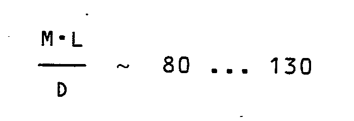

worin M der Anteil von Sauerstoff im Einsatzgas des Ozonerzeugers in Gew.-%, L den Zahlenwert der Leistungsdichte in kW pro m² aktive Elektrodenoberfläche und D den Zahlenwert des absoluten Drucks im Ozonerzeuger in bar bedeuten.The economy of the entire plant is also higher because the air separation plant can be operated in one area or can be designed a priori in such a way that the oxygen leaving this plant does not have to be technically pure, but still a large proportion of nitrogen - preferably 20 may contain up to 5% by weight. For this "mixing" of stick Substance to the feed gas results in an improvement in the specific energy requirement of the ozone generator on the one hand and on the other hand results in a shift in the optimum pressure for ozone generation against 2.5 to 3.5 bar absolute, with an O₂ concentration of over 80% by weight and with one-sided cooling the rule of thumb
where M is the percentage of oxygen in the feed gas of the ozone generator in% by weight, L is the numerical value of the power density in kW per m² of active electrode surface and D is the numerical value of the absolute pressure in the ozone generator in bar.
Claims (2)
- die Spaltweite ist überall annähernd gleich gross und beträgt höchstens 1 mm;
- das Einsatzgas enthält 30 bis 98 Gew.-%, vorzugsweise 85 bis 95 Gew.-% Sauerstoff, der Rest ist im wesentlichen Stickstoff
- die Leistungsdichte beträgt bei einseitiger Kühlung der Elektroden 2,5 bis 5 kW pro m² aktive Elektrodenfläche, bei beidseitiger Kühlung ist die Leistungsdichte um den Faktor 4 bis 5 höher,
- in Strömungsrichtung des Einsatzgases gesehen ist vor dem Ozonerzeuger (11, 12) ein Druckerzeuger (9) vorgesehen zur Aufrechterhaltung eines Druckes im Ozonerzeuger auf mindestens 2 bar absolut.1. Device for generating ozone with an electric ozone generator, through the discharge gap of which a nitrogen and oxygen-containing feed gas can be passed, with means for cooling the electrodes delimiting the discharge gap, characterized by the combination of the following features:
- The gap width is approximately the same everywhere and is at most 1 mm;
- The feed gas contains 30 to 98 wt .-%, preferably 85 to 95 wt .-% oxygen, the rest is essentially nitrogen
- the power density is 2.5 to 5 kW per m² of active electrode area when the electrodes are cooled on one side, the power density is 4 to 5 times higher when cooling on both sides,
- Seen in the flow direction of the feed gas, a pressure generator (9) is provided in front of the ozone generator (11, 12) for maintaining a pressure in the ozone generator to at least 2 bar absolute.
Priority Applications (1)
| Application Number | Priority Date | Filing Date | Title |
|---|---|---|---|
| AT87108267T ATE76386T1 (en) | 1986-07-03 | 1987-06-08 | PROCESS FOR GENERATING OZONE. |
Applications Claiming Priority (2)
| Application Number | Priority Date | Filing Date | Title |
|---|---|---|---|
| CH2680/86 | 1986-07-03 | ||
| CH268086 | 1986-07-03 |
Publications (2)
| Publication Number | Publication Date |
|---|---|
| EP0253131A1 true EP0253131A1 (en) | 1988-01-20 |
| EP0253131B1 EP0253131B1 (en) | 1992-05-20 |
Family
ID=4239162
Family Applications (1)
| Application Number | Title | Priority Date | Filing Date |
|---|---|---|---|
| EP87108267A Expired - Lifetime EP0253131B1 (en) | 1986-07-03 | 1987-06-08 | Ozone production process |
Country Status (3)
| Country | Link |
|---|---|
| EP (1) | EP0253131B1 (en) |
| AT (1) | ATE76386T1 (en) |
| DE (1) | DE3779196D1 (en) |
Cited By (2)
| Publication number | Priority date | Publication date | Assignee | Title |
|---|---|---|---|---|
| US5039314A (en) * | 1989-06-26 | 1991-08-13 | Voest-Alpine Industrienlagenbau Gesellschaft M.B.H. | Method for producing oxygen and/or ozone |
| EP0579060A1 (en) * | 1992-07-03 | 1994-01-19 | Ebara Corporation | Ozonizer |
Citations (4)
| Publication number | Priority date | Publication date | Assignee | Title |
|---|---|---|---|---|
| US2872397A (en) * | 1955-01-10 | 1959-02-03 | Union Carbide Corp | Method and apparatus for producing ozone-carrier gas mixture |
| DE3220018A1 (en) * | 1981-07-10 | 1983-01-20 | BBC Aktiengesellschaft Brown, Boveri & Cie., 5401 Baden, Aargau | Process and apparatus for producing ozone |
| DE3427274A1 (en) * | 1984-06-26 | 1986-01-02 | BBC Aktiengesellschaft Brown, Boveri & Cie., Baden, Aargau | Process for generating ozone |
| DE3430011A1 (en) * | 1984-08-16 | 1986-02-27 | Messer Griesheim Gmbh, 6000 Frankfurt | Process for generating ozone |
-
1987
- 1987-06-08 AT AT87108267T patent/ATE76386T1/en active
- 1987-06-08 DE DE8787108267T patent/DE3779196D1/en not_active Expired - Lifetime
- 1987-06-08 EP EP87108267A patent/EP0253131B1/en not_active Expired - Lifetime
Patent Citations (4)
| Publication number | Priority date | Publication date | Assignee | Title |
|---|---|---|---|---|
| US2872397A (en) * | 1955-01-10 | 1959-02-03 | Union Carbide Corp | Method and apparatus for producing ozone-carrier gas mixture |
| DE3220018A1 (en) * | 1981-07-10 | 1983-01-20 | BBC Aktiengesellschaft Brown, Boveri & Cie., 5401 Baden, Aargau | Process and apparatus for producing ozone |
| DE3427274A1 (en) * | 1984-06-26 | 1986-01-02 | BBC Aktiengesellschaft Brown, Boveri & Cie., Baden, Aargau | Process for generating ozone |
| DE3430011A1 (en) * | 1984-08-16 | 1986-02-27 | Messer Griesheim Gmbh, 6000 Frankfurt | Process for generating ozone |
Cited By (3)
| Publication number | Priority date | Publication date | Assignee | Title |
|---|---|---|---|---|
| US5039314A (en) * | 1989-06-26 | 1991-08-13 | Voest-Alpine Industrienlagenbau Gesellschaft M.B.H. | Method for producing oxygen and/or ozone |
| EP0579060A1 (en) * | 1992-07-03 | 1994-01-19 | Ebara Corporation | Ozonizer |
| US5538695A (en) * | 1992-07-03 | 1996-07-23 | Ebara Corporation | Ozonizer |
Also Published As
| Publication number | Publication date |
|---|---|
| EP0253131B1 (en) | 1992-05-20 |
| ATE76386T1 (en) | 1992-06-15 |
| DE3779196D1 (en) | 1992-06-25 |
Similar Documents
| Publication | Publication Date | Title |
|---|---|---|
| EP0146124B1 (en) | Pressure swing adsorption process | |
| EP0022178B1 (en) | Cyclic adsorption process for the separation of a gas mixture | |
| DE60102788T3 (en) | Integrated process for air separation and energy production | |
| EP0053837B1 (en) | Adsorption process and installation for carrying out the process | |
| DE3304227A1 (en) | Process and apparatus for pressure swing adsorption | |
| DE2916585A1 (en) | PRESSURE CHANGE ADSORPTION METHOD | |
| DE3132758A1 (en) | ABSORPTION PROCEDURE | |
| DE3132572A1 (en) | METHOD FOR THE ADSORPTIVE DISASSEMBLY OF A GAS MIXTURE | |
| EP0066869A2 (en) | Process for separating gas mixtures by the pressure-swing technique | |
| DE60013212T2 (en) | Method for controlling the concentration of a gas mixture | |
| EP0595100A1 (en) | Process for producing highly pure streams of hydrogen and carbon monoxide | |
| DE2146403A1 (en) | METHOD AND DEVICE FOR PURIFYING ORGANICALLY POLLUTED WASTE WATER | |
| DE2743861C2 (en) | Method for separating a gas mixture | |
| DE2624346C2 (en) | ||
| EP0015413B1 (en) | Pressure swing adsorption process for the decomposition or purification of gas mixtures | |
| DE727107C (en) | Process for the simultaneous extraction of krypton and nitrogen from air | |
| EP0262449A2 (en) | Process for producing ozone | |
| EP0253131B1 (en) | Ozone production process | |
| WO1986006710A1 (en) | Oxidation method and device by means of an anthraquinone process for producing hydrogen peroxyde | |
| EP0799633A1 (en) | Process and apparatus for eliminating carbon monoxide and/or hydrogen from an air stream | |
| DE2522324A1 (en) | Counter current gas-liquid contactor - using jet ejector effect from liquid input to pull gas through column | |
| DE60308185T2 (en) | METHOD AND DEVICE FOR PREPARING AMMONIA CYNTHESEGAS | |
| DE2610227A1 (en) | METHOD AND DEVICE FOR GENERATING AND RECOVERING OZONE | |
| DE60110540T2 (en) | Pressure swing adsorption process on a very large scale | |
| EP0325956A2 (en) | Process for cleaning a gaseous mixture |
Legal Events
| Date | Code | Title | Description |
|---|---|---|---|
| PUAI | Public reference made under article 153(3) epc to a published international application that has entered the european phase |
Free format text: ORIGINAL CODE: 0009012 |
|
| AK | Designated contracting states |
Kind code of ref document: A1 Designated state(s): AT CH DE FR GB IT LI |
|
| 17P | Request for examination filed |
Effective date: 19880627 |
|
| 17Q | First examination report despatched |
Effective date: 19891127 |
|
| RAP1 | Party data changed (applicant data changed or rights of an application transferred) |
Owner name: OZONIA AG |
|
| GRAA | (expected) grant |
Free format text: ORIGINAL CODE: 0009210 |
|
| AK | Designated contracting states |
Kind code of ref document: B1 Designated state(s): AT CH DE FR GB IT LI |
|
| PG25 | Lapsed in a contracting state [announced via postgrant information from national office to epo] |
Ref country code: IT Free format text: LAPSE BECAUSE OF FAILURE TO SUBMIT A TRANSLATION OF THE DESCRIPTION OR TO PAY THE FEE WITHIN THE PRE;WARNING: LAPSES OF ITALIAN PATENTS WITH EFFECTIVE DATE BEFORE 2007 MAY HAVE OCCURRED AT ANY TIME BEFORE 2007. THE CORRECT EFFECTIVE DATE MAY BE DIFFERENT FROM THE ONE RECORDED.SCRIBED TIME-LIMIT Effective date: 19920520 |
|
| REF | Corresponds to: |
Ref document number: 76386 Country of ref document: AT Date of ref document: 19920615 Kind code of ref document: T |
|
| PG25 | Lapsed in a contracting state [announced via postgrant information from national office to epo] |
Ref country code: AT Effective date: 19920608 |
|
| REF | Corresponds to: |
Ref document number: 3779196 Country of ref document: DE Date of ref document: 19920625 |
|
| GBT | Gb: translation of ep patent filed (gb section 77(6)(a)/1977) | ||
| ET | Fr: translation filed | ||
| REG | Reference to a national code |
Ref country code: CH Ref legal event code: PFA Free format text: OZONIA AG |
|
| PLBE | No opposition filed within time limit |
Free format text: ORIGINAL CODE: 0009261 |
|
| STAA | Information on the status of an ep patent application or granted ep patent |
Free format text: STATUS: NO OPPOSITION FILED WITHIN TIME LIMIT |
|
| 26N | No opposition filed | ||
| PGFP | Annual fee paid to national office [announced via postgrant information from national office to epo] |
Ref country code: GB Payment date: 19970616 Year of fee payment: 11 |
|
| PGFP | Annual fee paid to national office [announced via postgrant information from national office to epo] |
Ref country code: FR Payment date: 19970620 Year of fee payment: 11 Ref country code: DE Payment date: 19970620 Year of fee payment: 11 |
|
| PGFP | Annual fee paid to national office [announced via postgrant information from national office to epo] |
Ref country code: CH Payment date: 19970627 Year of fee payment: 11 |
|
| PG25 | Lapsed in a contracting state [announced via postgrant information from national office to epo] |
Ref country code: GB Free format text: LAPSE BECAUSE OF NON-PAYMENT OF DUE FEES Effective date: 19980608 |
|
| PG25 | Lapsed in a contracting state [announced via postgrant information from national office to epo] |
Ref country code: CH Free format text: LAPSE BECAUSE OF NON-PAYMENT OF DUE FEES Effective date: 19980630 Ref country code: LI Free format text: LAPSE BECAUSE OF NON-PAYMENT OF DUE FEES Effective date: 19980630 |
|
| GBPC | Gb: european patent ceased through non-payment of renewal fee |
Effective date: 19980608 |
|
| REG | Reference to a national code |
Ref country code: CH Ref legal event code: PL |
|
| PG25 | Lapsed in a contracting state [announced via postgrant information from national office to epo] |
Ref country code: FR Free format text: LAPSE BECAUSE OF NON-PAYMENT OF DUE FEES Effective date: 19990226 |
|
| PG25 | Lapsed in a contracting state [announced via postgrant information from national office to epo] |
Ref country code: DE Free format text: LAPSE BECAUSE OF NON-PAYMENT OF DUE FEES Effective date: 19990401 |
|
| REG | Reference to a national code |
Ref country code: FR Ref legal event code: ST |